EP4455435A1 - Chain actuator particularly for frame and window closure systems - Google Patents
Chain actuator particularly for frame and window closure systems Download PDFInfo
- Publication number
- EP4455435A1 EP4455435A1 EP24167834.1A EP24167834A EP4455435A1 EP 4455435 A1 EP4455435 A1 EP 4455435A1 EP 24167834 A EP24167834 A EP 24167834A EP 4455435 A1 EP4455435 A1 EP 4455435A1
- Authority
- EP
- European Patent Office
- Prior art keywords
- chain
- box
- shaped body
- gas spring
- operating lever
- Prior art date
- Legal status (The legal status is an assumption and is not a legal conclusion. Google has not performed a legal analysis and makes no representation as to the accuracy of the status listed.)
- Granted
Links
Images



Classifications
-
- E—FIXED CONSTRUCTIONS
- E05—LOCKS; KEYS; WINDOW OR DOOR FITTINGS; SAFES
- E05F—DEVICES FOR MOVING WINGS INTO OPEN OR CLOSED POSITION; CHECKS FOR WINGS; WING FITTINGS NOT OTHERWISE PROVIDED FOR, CONCERNED WITH THE FUNCTIONING OF THE WING
- E05F15/00—Power-operated mechanisms for wings
- E05F15/60—Power-operated mechanisms for wings using electrical actuators
- E05F15/603—Power-operated mechanisms for wings using electrical actuators using rotary electromotors
- E05F15/611—Power-operated mechanisms for wings using electrical actuators using rotary electromotors for swinging wings
- E05F15/616—Power-operated mechanisms for wings using electrical actuators using rotary electromotors for swinging wings operated by push-pull mechanisms
- E05F15/619—Power-operated mechanisms for wings using electrical actuators using rotary electromotors for swinging wings operated by push-pull mechanisms using flexible or rigid rack-and-pinion arrangements
-
- E—FIXED CONSTRUCTIONS
- E05—LOCKS; KEYS; WINDOW OR DOOR FITTINGS; SAFES
- E05F—DEVICES FOR MOVING WINGS INTO OPEN OR CLOSED POSITION; CHECKS FOR WINGS; WING FITTINGS NOT OTHERWISE PROVIDED FOR, CONCERNED WITH THE FUNCTIONING OF THE WING
- E05F11/00—Man-operated mechanisms for operating wings, including those which also operate the fastening
- E05F11/02—Man-operated mechanisms for operating wings, including those which also operate the fastening for wings in general, e.g. fanlights
- E05F11/04—Man-operated mechanisms for operating wings, including those which also operate the fastening for wings in general, e.g. fanlights with cords, chains or cables
- E05F11/06—Man-operated mechanisms for operating wings, including those which also operate the fastening for wings in general, e.g. fanlights with cords, chains or cables in guide-channels
-
- E—FIXED CONSTRUCTIONS
- E05—LOCKS; KEYS; WINDOW OR DOOR FITTINGS; SAFES
- E05F—DEVICES FOR MOVING WINGS INTO OPEN OR CLOSED POSITION; CHECKS FOR WINGS; WING FITTINGS NOT OTHERWISE PROVIDED FOR, CONCERNED WITH THE FUNCTIONING OF THE WING
- E05F5/00—Braking devices, e.g. checks; Stops; Buffers
- E05F5/02—Braking devices, e.g. checks; Stops; Buffers specially for preventing the slamming of swinging wings during final closing movement, e.g. jamb stops
-
- E—FIXED CONSTRUCTIONS
- E05—LOCKS; KEYS; WINDOW OR DOOR FITTINGS; SAFES
- E05Y—INDEXING SCHEME ASSOCIATED WITH SUBCLASSES E05D AND E05F, RELATING TO CONSTRUCTION ELEMENTS, ELECTRIC CONTROL, POWER SUPPLY, POWER SIGNAL OR TRANSMISSION, USER INTERFACES, MOUNTING OR COUPLING, DETAILS, ACCESSORIES, AUXILIARY OPERATIONS NOT OTHERWISE PROVIDED FOR, APPLICATION THEREOF
- E05Y2201/00—Constructional elements; Accessories therefor
- E05Y2201/40—Motors; Magnets; Springs; Weights; Accessories therefor
- E05Y2201/47—Springs
- E05Y2201/478—Gas springs
-
- E—FIXED CONSTRUCTIONS
- E05—LOCKS; KEYS; WINDOW OR DOOR FITTINGS; SAFES
- E05Y—INDEXING SCHEME ASSOCIATED WITH SUBCLASSES E05D AND E05F, RELATING TO CONSTRUCTION ELEMENTS, ELECTRIC CONTROL, POWER SUPPLY, POWER SIGNAL OR TRANSMISSION, USER INTERFACES, MOUNTING OR COUPLING, DETAILS, ACCESSORIES, AUXILIARY OPERATIONS NOT OTHERWISE PROVIDED FOR, APPLICATION THEREOF
- E05Y2201/00—Constructional elements; Accessories therefor
- E05Y2201/60—Suspension or transmission members; Accessories therefor
- E05Y2201/622—Suspension or transmission members elements
- E05Y2201/644—Flexible elongated pulling elements
- E05Y2201/656—Chains
-
- E—FIXED CONSTRUCTIONS
- E05—LOCKS; KEYS; WINDOW OR DOOR FITTINGS; SAFES
- E05Y—INDEXING SCHEME ASSOCIATED WITH SUBCLASSES E05D AND E05F, RELATING TO CONSTRUCTION ELEMENTS, ELECTRIC CONTROL, POWER SUPPLY, POWER SIGNAL OR TRANSMISSION, USER INTERFACES, MOUNTING OR COUPLING, DETAILS, ACCESSORIES, AUXILIARY OPERATIONS NOT OTHERWISE PROVIDED FOR, APPLICATION THEREOF
- E05Y2201/00—Constructional elements; Accessories therefor
- E05Y2201/60—Suspension or transmission members; Accessories therefor
- E05Y2201/622—Suspension or transmission members elements
- E05Y2201/71—Toothed gearing
- E05Y2201/722—Racks
- E05Y2201/724—Flexible
-
- E—FIXED CONSTRUCTIONS
- E05—LOCKS; KEYS; WINDOW OR DOOR FITTINGS; SAFES
- E05Y—INDEXING SCHEME ASSOCIATED WITH SUBCLASSES E05D AND E05F, RELATING TO CONSTRUCTION ELEMENTS, ELECTRIC CONTROL, POWER SUPPLY, POWER SIGNAL OR TRANSMISSION, USER INTERFACES, MOUNTING OR COUPLING, DETAILS, ACCESSORIES, AUXILIARY OPERATIONS NOT OTHERWISE PROVIDED FOR, APPLICATION THEREOF
- E05Y2900/00—Application of doors, windows, wings or fittings thereof
- E05Y2900/10—Application of doors, windows, wings or fittings thereof for buildings or parts thereof
- E05Y2900/13—Type of wing
- E05Y2900/148—Windows
Definitions
- the present invention relates to a chain actuator particularly for frame and window closing systems.
- chain actuators are especially used for actuating window units intended to be placed in positions which are difficult to access, as in the case, for example, of skylights.
- a type of chain actuator which is increasingly more widespread is a chain actuator which comprises:
- the gas spring helps maintain the position acquired by the operating lever with respect to the box-shaped body, opposing any stressing forces resulting from the window should it in turn be stressed, for example, by the wind.
- the so-called "rigid chain” is a chain which has links which are connected together and shaped so as to rotate relative to each other about a hinging axis, through a small angle, namely each link is shaped so as to have an end-of-rotation portion which prevents a following link hinged therewith from rotating in a direction, for example an anti-clockwise direction, beyond a certain predefined angle.
- each of the links rests on the following link emerging from the box-shaped body, so as to be able to mutually support each other and assume a stable aligned configuration, namely "rigid chain” configuration, which allows the said chain to operate with a thrusting force, for example so as to support the weight of a window and keep it in an open position with respect to a frame.
- Such a chain actuator is configured to extend or retract the chain so that the at least partial extension of the chain is followed by a rotation of the window away from the frame, and the retraction of the chain instead performs a rotation of the window towards the frame.
- Chain actuators with an auxiliary gas spring although known and widespread, have a number of aspects which are subject to improvement.
- a first aspect is associated with the fact that the gas spring must be able to exert a pulling force on the operating lever, when the window is open, so as to keep the links of the rigid chain pressed, namely compressed, against each other also in windy weather conditions and at the same time must have a size such as not to exceed the dimensions which are normally acceptable for chain actuators of the known type.
- the rigid chain C is normally positioned so that:
- L0 denotes the overall length of the box-shaped body D in the direction of longitudinal extension of the said box-shaped body D.
- a long rigid chain means that, in addition to the corresponding costs which are proportional to the length of the rigid chain itself, the longitudinal dimension of the box-shaped body must also be determined in relation to the length of the rigid chain, since the chain in the collapsed non-operative arrangement is housed inside an internal compartment of the box-shaped body, the length of which may not be less than half the length of the rigid chain in the completely extended condition when the links are arranged along two essentially parallel rows inside the box-shaped body, or the length of which may not be less than one third of the length of the rigid chain when the links are arranged along three essentially parallel rows inside the box-shaped body.
- the compartment containing the rigid chain, and therefore the box-shaped body as a whole is all the longer, and therefore bulkier, the longer the rigid chain.
- a second drawback resulting from the length of the rigid chain is the operating speed of the chain actuator: the further away the through-opening E is situated from the pivoting means F the greater is the distance which the first link of the rigid chain C must travel in order to bring the operating lever M into the desired angular arrangement.
- the technical problem posed and solved by the present invention is therefore that of providing a chain actuator particularly for frame and window closing systems which is able to overcome the drawbacks mentioned with reference to the prior art.
- An important object of the present invention is to provide a chain actuator, the longitudinal dimension of which is smaller compared to the prior art, for the same components arranged inside the box-shaped body of the said chain actuator.
- Another object of the present invention is to provide a chain actuator which is able to speed up the opening and closing actions compared to similar chain actuators of the known type.
- an embodiment of a chain actuator, particularly for frame and window closing systems, according to the invention is denoted overall by the number 10.
- Such a chain actuator 10 comprises:
- the particular feature of the chain actuator 10 according to the invention lies in the fact that a first distance L10 between the through-opening 18 and the pivoting means 13 is smaller than a second distance L20 between the second hinge 22 of the second end 19b of the auxiliary gas spring 10 and said pivoting means 13.
- the point of the through-opening 10 to be taken into consideration for the measurement of the first distance L10 is a middle point of the longitudinal dimension of the through-opening 18.
- a third distance L30 between the point where the rigid chain 14 is fastened to the operating lever 12 and the pivoting means 13 is greater than a fourth distance L40 between the first end 19a of the gas spring 19 and the pivoting means 13.
- the pivoting means 13 comprise, in the present example of embodiment, a projecting body 25 fixed to the box-shaped body 11, and a lever pin 26.
- the projecting body 25 consists for example of a parallelepiped block, for example made of metallic material.
- the point of the pivoting means 13 to be taken into consideration for measurement of the first distance L10 is the axis of the lever pin 26.
- the operating lever 12 comprises a fork-shaped hinging end 12a configured for rotatable coupling with the projecting body 25 by means of the lever pin 26.
- the rigid chain 14 and the gas spring 19 are arranged so as to operate side-by-side between the box-shaped body 11 and the operating lever 12.
- the rigid chain 14 is arranged so as to operate in a first operating plane P1 and the gas spring 19 is arranged so as to operate in a second operating plane P2 parallel to the first operating plane P1.
- the operating lever 12 has a longitudinal recess 28 for the gas spring 19 in the shortened rest arrangement.
- the longitudinal recess 28 is configured to accommodate the gas spring 19 in the shortened rest arrangement.
- the shortened rest arrangement occurs when the rigid chain 14 is in the folded-up non-operative arrangement.
- Said longitudinal recess 28 is defined along a first lateral portion 29 of the operating lever 12.
- the fastening point 20 of the rigid chain 14 is positioned on the second opposite lateral portion 30 of the operating lever 12.
- the two lateral portions 29 and 30 are obviously arranged alongside and adjacent in a transverse direction with respect to a direction parallel to the operating planes P1 and P2.
- the two lateral portions 29 and 30 correspond to the two opposite sides of the operating lever 12 in the main direction of the extension of the latter, as is clearly visible in Figure 6 .
- the rigid chain 14 comprises, or is composed of, in a known manner, a plurality of links 41, or link elements, or segments, which are arranged in series between a head segment 42, connected to the operating lever 12, and a tail segment 44.
- the head segment 42 and the tail segment 44 constitute, therefore, the end segments of the rigid chain 40.
- each link of the plurality of links 41 has a direction of extension S and is connected to at least one further adjacent, neighbouring or adjoining link of the plurality of links 41, 42 and 44 so as to rotate with respect to the latter reversibly about a hinge axis C, shown by way of example in Figure 7 , in a jamming direction or in a winding direction so that its direction of extension S is oriented respectively between a jamming angle, or jamming arrangement, and a winding angle or winding arrangement.
- each link of the plurality of links 41, 42 and 44 is associated rotatably with a further link so as to be able to rotate with respect to the latter about a hinge axis C, the latter being shown by way of example in Figure 7 , in a jamming direction or in an opposite winding direction.
- each segment of the plurality of segments 41 may be arranged, with respect to the further segment with which it is rotatably associated, so as to orient its direction of extension S between a jamming angle and a winding angle.
- the winding direction may be the direction of the rotation about the hinge axis C, which allows a link 41 to orient its direction of extension S at the winding angle.
- the winding direction may be the direction of the rotation about the hinge axis C, which allows one link of the plurality of links 41 to orient its direction of extension S at the jamming angle.
- each link of the plurality of segments 41 in particular of each of the links situated between the head link 42 and the links 41 engaged by the gearmotor unit 15, has its direction of extension S substantially parallel to the direction of extension S of the further segment so as to exert a stressing force along an operating direction D and move the operating lever 12 with respect to the box-shaped body 11.
- the operating direction D is graphically indicated by way of example in Figure 4 .
- the rigid chain 12 has a sufficient rigidity to exert a stressing force on the operating lever 12 along said operating direction D.
- Said operating direction D therefore represents a stressing direction, such as a pulling or pushing force, along which the rigid chain 12 operates the operating lever 12.
- the plane in which the jamming angle and the winding angle lie are defined, or lie, is the first operating plane P1 of the rigid chain 12.
- the gearmotor unit 15 comprises an electric motor 45 designed to transfer the driving torque to an output gear 46 connected directly to or coaxially with a pinion 47 configured to mesh with the rigid chain 12.
- the pinion 47 is positioned so as to rotate in the first operating plane P1, i.e. with its axis of rotation perpendicular to the first operating plane P1.
- the first operating plane P1 does not coincide with the longitudinal median plane PM of the box-shaped body 11, as shown in Figure 7 .
- the first operating plane P1 is laterally displaced with respect to the median plane PM.
- the second operating plane P2, of the auxiliary gas spring 10 is laterally displaced with respect to the median plane PM, on the opposite to the side where the first operating plane P1 is defined.
- the through-opening 18 is defined in a cover 50 which is fixed over an open assembly window 51 on the box-shaped body 11.
- the chain actuator 10 owing to the displaced position of the rigid chain 14 and the gas spring 19, is able to fulfil the aforementioned task and objects.
- the chain actuator 10 according to the present invention therefore provides several significant advantages.
- a chain actuator has been provided where the longitudinal dimension is smaller compared to the prior art, for the same components arranged inside the box-shaped body of the said chain actuator and for the same auxiliary gas spring.
- the fourth distance L40 is greater than or the same as the third distance L30; namely the pushing point of the rigid chain on the operating lever is located at the same distance or at a smaller distance from the hinging means of the operating lever than the pushing/pulling point of the gas spring on the operating lever.
- the present invention provides a chain actuator which has a faster opening and closing action compared to similar chain actuators of the known type, owing to the smaller length of the rigid chain.
- the present invention provides a chain actuator which has a lower cost compared to similar chain actuators of the known type, owing to the significant reduction in the number of links of the rigid chain.
- the invention provides a chain actuator which is simple to use, in the same manner as that which is known.
Landscapes
- Power-Operated Mechanisms For Wings (AREA)
Abstract
- a box-shaped body (11), with a mainly longitudinal extension;
- an operating lever (12) pivotably mounted by means of pivoting means (13) at one end (11a) of the box-shaped body (11);
- a rigid push-and-pull chain (14);
- a gearmotor unit (15) configured for the movement of the rigid chain (14), said gearmotor unit (15) being positioned in a first internal compartment (16) of said box-shaped body (11);
- a second internal compartment (17) of said box-shaped body (11), configured to accommodate said rigid chain (14) in the folded-up non-operative arrangement;
- a through-opening (18) for the passage of said rigid chain (14), said through-opening (18) being defined on said box-shaped body (11);
- a gas spring (19) fastened at a first end (19a) thereof to said operating lever (12) by means of a first hinge (21) and, at the second opposite end (19b), to said box-shaped body (11) by means of a second hinge (22).
Description
- The present invention relates to a chain actuator particularly for frame and window closing systems.
- Nowadays, actuators for window units called "chain actuators" are known.
- In the sector relating to the manufacture of window units, chain actuators are especially used for actuating window units intended to be placed in positions which are difficult to access, as in the case, for example, of skylights.
- A type of chain actuator which is increasingly more widespread is a chain actuator which comprises:
- a longitudinally extending box-shaped body, which is normally fixed to an upright or to the upper crosspiece of a window unit;
- an operating lever which is pivotably mounted by means of pivoting means at one end of said box-shaped body, where said operating lever is usually configured to move the window which is hinged with the frame;
- a rigid pull-and-push chain, which is configured to assume an operative, pushing or pulling, extended arrangement outside the box-shaped body or a non-operative folded-up arrangement inside the box-shaped body; the rigid chain is positioned and configured so as to exert a pushing or pulling force on the operating lever; the rigid chain is fastened at a first end thereof to the operating lever at a fastening point and, at a second opposite end, is fastened inside the box-shaped body;
- a gearmotor unit configured for the movement of said rigid chain, said gearmotor unit being positioned in a first internal compartment of the box-shaped body;
- a second internal compartment of the box-shaped body, configured to accommodate the rigid chain in the folded-up non-operative arrangement;
- a through-opening for the passage of the rigid chain, said through-opening being defined on the said box-shaped body;
- an auxiliary gas spring, which auxiliary gas spring is fastened at a first end thereof to the operating lever by means of a first hinge, and at the second opposite end to the box-shaped body by means of a second hinge.
- The gas spring helps maintain the position acquired by the operating lever with respect to the box-shaped body, opposing any stressing forces resulting from the window should it in turn be stressed, for example, by the wind.
- It is in fact known that the so-called "rigid chain" is a chain which has links which are connected together and shaped so as to rotate relative to each other about a hinging axis, through a small angle, namely each link is shaped so as to have an end-of-rotation portion which prevents a following link hinged therewith from rotating in a direction, for example an anti-clockwise direction, beyond a certain predefined angle.
- In this way, as the chain gradually extends outside of the box-shaped body, each of the links rests on the following link emerging from the box-shaped body, so as to be able to mutually support each other and assume a stable aligned configuration, namely "rigid chain" configuration, which allows the said chain to operate with a thrusting force, for example so as to support the weight of a window and keep it in an open position with respect to a frame.
- Such a chain actuator is configured to extend or retract the chain so that the at least partial extension of the chain is followed by a rotation of the window away from the frame, and the retraction of the chain instead performs a rotation of the window towards the frame.
- Chain actuators with an auxiliary gas spring, although known and widespread, have a number of aspects which are subject to improvement.
- A first aspect is associated with the fact that the gas spring must be able to exert a pulling force on the operating lever, when the window is open, so as to keep the links of the rigid chain pressed, namely compressed, against each other also in windy weather conditions and at the same time must have a size such as not to exceed the dimensions which are normally acceptable for chain actuators of the known type.
- An example of a chain actuator of the known type is schematically shown in
Figure 1 and is indicated there overall by the letter A. - During adaptation to the dimensions of the gas spring B, the rigid chain C is normally positioned so that:
- the distance L1 between the through-opening E on the box-shaped body D, from which the rigid chain C emerges, and the pivoting means F is greater than the distance L2 between the hinge G on the box-shaped body D of the gas spring B and said pivoting means F;
- and the distance L3 between the point H where said rigid chain C is fastened to said operating lever M and the pivoting means F is greater than the distance L4 between the hinge N of the gas spring B with the lever M and the pivoting means F.
- With this relative arrangement of the rigid chain C and the gas spring B, in order to perform rotation of the operating lever N with respect to the box-shaped body D such as to cause the opening of a window with respect to the frame through 90°, it is necessary to have a relatively long rigid chain C, i.e. one which is composed of a relatively large number of links.
- L0 denotes the overall length of the box-shaped body D in the direction of longitudinal extension of the said box-shaped body D.
- A long rigid chain means that, in addition to the corresponding costs which are proportional to the length of the rigid chain itself, the longitudinal dimension of the box-shaped body must also be determined in relation to the length of the rigid chain, since the chain in the collapsed non-operative arrangement is housed inside an internal compartment of the box-shaped body, the length of which may not be less than half the length of the rigid chain in the completely extended condition when the links are arranged along two essentially parallel rows inside the box-shaped body, or the length of which may not be less than one third of the length of the rigid chain when the links are arranged along three essentially parallel rows inside the box-shaped body.
- Therefore, inside the box-shaped body of the chain actuator, for the same dimensions of the motor, gearmotor and other electrical power supply components, the compartment containing the rigid chain, and therefore the box-shaped body as a whole, is all the longer, and therefore bulkier, the longer the rigid chain.
- A second drawback resulting from the length of the rigid chain is the operating speed of the chain actuator: the further away the through-opening E is situated from the pivoting means F the greater is the distance which the first link of the rigid chain C must travel in order to bring the operating lever M into the desired angular arrangement.
- The technical problem posed and solved by the present invention is therefore that of providing a chain actuator particularly for frame and window closing systems which is able to overcome the drawbacks mentioned with reference to the prior art.
- An important object of the present invention is to provide a chain actuator, the longitudinal dimension of which is smaller compared to the prior art, for the same components arranged inside the box-shaped body of the said chain actuator.
- Another object of the present invention is to provide a chain actuator which is able to speed up the opening and closing actions compared to similar chain actuators of the known type.
- Yet another object of the present invention is to provide a chain actuator which has a lower cost compared to similar chain actuators of the known type. Another object of the invention is to provide a chain actuator which is simple to use in the manner of that which is known.
- The aforementioned task and the objects are solved by a chain actuator particularly for frame and window closing systems according to claim 1. Preferred characteristic features of the present invention are the subject of the dependent claims.
- Reference will be made to the figures of the attached drawings in which:
- ▪
Figure 1 shows a plan view of a chain actuator of the known type; - ▪
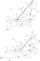
Figure 2 shows a plan view of a chain actuator according to the invention; - ▪
Figure 3 shows a perspective view of a chain actuator according to the invention; - ▪
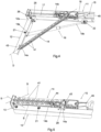
Figure 4 shows a perspective cut-away view of the chain actuator according to the invention, in an open arrangement; - ▪
Figure 5 shows a perspective cut-away view of the chain actuator according to the invention, in a closed arrangement; - ▪
Figure 6 shows a side view of the chain actuator according to the invention, in an open arrangement; - ▪
Figure 7 shows a cross-sectional view of the actuator according to the invention. - The thicknesses and curvatures shown in the figures mentioned above must be understood as being purely exemplary and are generally on a larger scale and not necessarily shown in proportion.
- Below an embodiment of the invention will be described with reference to the figures mentioned above.
- Similar components are indicated in the various figures by the same reference number.
- In the detailed description which follows, embodiments and variants in addition to those embodiments and variants already considered in the same description will be described only with regard to their differences from that already illustrated.
- Furthermore, the various embodiments and variants described below may be combined, where compatible.
- With reference to the aforementioned figures, an embodiment of a chain actuator, particularly for frame and window closing systems, according to the invention is denoted overall by the
number 10. - Such a
chain actuator 10 comprises: - a box-
shaped body 11, with a mainly longitudinal extension; - an
operating lever 12 pivotably mounted by means of pivoting means 13 at oneend 11a of the box-shaped body 11; - a rigid pull-and-
push chain 14, which is configured to assume an operative extended arrangement outside the box-shaped body 11 or a non-operative folded-up arrangement inside the box-shaped body 11; saidrigid chain 14 is positioned and configured so as to exert a pushing or pulling force on theoperating lever 12; therigid chain 14 is fastened at afirst end 14a thereof to theoperating lever 12 at afastening point 20 and, at the secondopposite end 14b, is fastened inside the box-shaped body 11; - a
gearmotor unit 15 configured for the movement of saidrigid chain 14, saidgearmotor unit 15 being positioned in a firstinternal compartment 16 of the box-shaped body 11; - a second
internal compartment 17 of the box-shaped body 11, configured to accommodate therigid chain 14 in the folded-up non-operative arrangement, as shown by way of example inFigure 5 ; - a through-opening 18 for the passage of the
rigid chain 14, said through-opening 18 being defined on the box-shaped body 11; - a gas spring; said
gas spring 19 is used as an auxiliary element for helping maintain the position acquired by the operating lever with respect to the box-shaped body, opposing any stressing forces resulting from the window should it in turn be stressed, for example, by the wind; thegas spring 19 is fastened at afirst end 19a thereof to theoperating lever 12 by means of afirst hinge 21; theauxiliary gas spring 19 is fastened at the secondopposite end 19b to the box-shaped body 11 by means of asecond hinge 22. - The particular feature of the
chain actuator 10 according to the invention lies in the fact that a first distance L10 between the through-opening 18 and the pivoting means 13 is smaller than a second distance L20 between thesecond hinge 22 of thesecond end 19b of theauxiliary gas spring 10 and said pivoting means 13. - The point of the through-opening 10 to be taken into consideration for the measurement of the first distance L10 is a middle point of the longitudinal dimension of the through-opening 18.
- Preferably, but not exclusively, a third distance L30 between the point where the
rigid chain 14 is fastened to theoperating lever 12 and the pivoting means 13 is greater than a fourth distance L40 between thefirst end 19a of thegas spring 19 and the pivoting means 13. - The pivoting means 13 comprise, in the present example of embodiment, a projecting
body 25 fixed to the box-shaped body 11, and alever pin 26. - The projecting
body 25 consists for example of a parallelepiped block, for example made of metallic material. - The point of the pivoting means 13 to be taken into consideration for measurement of the first distance L10 is the axis of the
lever pin 26. - The operating
lever 12 comprises a fork-shapedhinging end 12a configured for rotatable coupling with the projectingbody 25 by means of thelever pin 26. Therigid chain 14 and thegas spring 19 are arranged so as to operate side-by-side between the box-shapedbody 11 and the operatinglever 12. - In particular, as schematically shown in
Figure 6 , therigid chain 14 is arranged so as to operate in a first operating plane P1 and thegas spring 19 is arranged so as to operate in a second operating plane P2 parallel to the first operating plane P1. - The operating
lever 12 has alongitudinal recess 28 for thegas spring 19 in the shortened rest arrangement. In other words, thelongitudinal recess 28 is configured to accommodate thegas spring 19 in the shortened rest arrangement. - The shortened rest arrangement occurs when the
rigid chain 14 is in the folded-up non-operative arrangement. - Said
longitudinal recess 28 is defined along a firstlateral portion 29 of the operatinglever 12. - The
fastening point 20 of therigid chain 14 is positioned on the secondopposite lateral portion 30 of the operatinglever 12. - The two
lateral portions lateral portions lever 12 in the main direction of the extension of the latter, as is clearly visible inFigure 6 . - The
rigid chain 14 comprises, or is composed of, in a known manner, a plurality oflinks 41, or link elements, or segments, which are arranged in series between ahead segment 42, connected to the operatinglever 12, and atail segment 44. Thehead segment 42 and thetail segment 44 constitute, therefore, the end segments of the rigid chain 40. - In particular, each link of the plurality of
links 41 has a direction of extension S and is connected to at least one further adjacent, neighbouring or adjoining link of the plurality oflinks Figure 7 , in a jamming direction or in a winding direction so that its direction of extension S is oriented respectively between a jamming angle, or jamming arrangement, and a winding angle or winding arrangement. In other words, each link of the plurality oflinks Figure 7 , in a jamming direction or in an opposite winding direction. In this way, each segment of the plurality ofsegments 41 may be arranged, with respect to the further segment with which it is rotatably associated, so as to orient its direction of extension S between a jamming angle and a winding angle. - Therefore, the winding direction may be the direction of the rotation about the hinge axis C, which allows a
link 41 to orient its direction of extension S at the winding angle. Vice versa, the winding direction may be the direction of the rotation about the hinge axis C, which allows one link of the plurality oflinks 41 to orient its direction of extension S at the jamming angle. - In general, the respective directions of extension S are schematically shown in broken lines in
Figure 5 . - At the jamming angle each link of the plurality of
segments 41, in particular of each of the links situated between thehead link 42 and thelinks 41 engaged by thegearmotor unit 15, has its direction of extension S substantially parallel to the direction of extension S of the further segment so as to exert a stressing force along an operating direction D and move the operatinglever 12 with respect to the box-shapedbody 11. - The operating direction D is graphically indicated by way of example in
Figure 4 . When thelinks rigid chain 12 are at the jamming angle, therigid chain 12 has a sufficient rigidity to exert a stressing force on the operatinglever 12 along said operating direction D. - Said operating direction D therefore represents a stressing direction, such as a pulling or pushing force, along which the
rigid chain 12 operates the operatinglever 12. - The plane in which the jamming angle and the winding angle lie are defined, or lie, is the first operating plane P1 of the
rigid chain 12. - The
gearmotor unit 15 comprises anelectric motor 45 designed to transfer the driving torque to anoutput gear 46 connected directly to or coaxially with apinion 47 configured to mesh with therigid chain 12. - The
pinion 47 is positioned so as to rotate in the first operating plane P1, i.e. with its axis of rotation perpendicular to the first operating plane P1. - In particular, the first operating plane P1 does not coincide with the longitudinal median plane PM of the box-shaped
body 11, as shown inFigure 7 . - Namely, the first operating plane P1 is laterally displaced with respect to the median plane PM.
- The second operating plane P2, of the
auxiliary gas spring 10, is laterally displaced with respect to the median plane PM, on the opposite to the side where the first operating plane P1 is defined. - The through-opening 18 is defined in a
cover 50 which is fixed over anopen assembly window 51 on the box-shapedbody 11. - The
chain actuator 10 according to the invention, owing to the displaced position of therigid chain 14 and thegas spring 19, is able to fulfil the aforementioned task and objects. - In particular, with L00 indicating the length of the box-shaped
body 11 in the direction of longitudinal extension of the same box-shapedbody 11, as can be clearly seen by comparingFigures 1 and 2 , for the same length LM of the gas spring B and 19, respectively, for the same length of the box-shaped body L0 and L00, and for the same position of the points where the gas spring is fastened to the box-shaped body and the operating lever, by arranging therigid chain 14 and thegas spring 19 so that they operate in operating planes P1 and P2 which are parallel, but separate, it is possible to use arigid chain 14 which is shorter than a rigid chain C of the prior art, and it is therefore possible to use a box-shapedbody 11 which is shorter than a box-shaped body D, with the same cross-section, of the prior art. - The
chain actuator 10 according to the present invention therefore provides several significant advantages. - In particular, with the present invention a chain actuator has been provided where the longitudinal dimension is smaller compared to the prior art, for the same components arranged inside the box-shaped body of the said chain actuator and for the same auxiliary gas spring.
- Furthermore, with the invention a chain actuator has been provided where it is possible to use a gas spring with larger dimensions compared to the similar solutions of the prior art, with a consequent increase in the thrusting force produced by the said gas spring, something which cannot be realized with the known solutions; said advantage is possible precisely because of the particular configuration of the actuator according to the present invention in which the gas spring is arranged alongside the rigid chain since it does not "intersect" the operating lever.
- Basically, with this invention there is the possibility of increasing the second distance L20 and/or the fourth distance L40 by displacing the pushing point towards the end of the operating
lever 12 and therefore into a more advantageous condition since situated further away from the hinging means 13; this can be achieved also for the same force of the gas spring. - According to a variation of embodiment of the chain actuator according to the invention, not shown for simpler illustration, the fourth distance L40 is greater than or the same as the third distance L30; namely the pushing point of the rigid chain on the operating lever is located at the same distance or at a smaller distance from the hinging means of the operating lever than the pushing/pulling point of the gas spring on the operating lever.
- Furthermore, the present invention provides a chain actuator which has a faster opening and closing action compared to similar chain actuators of the known type, owing to the smaller length of the rigid chain.
- Furthermore, the present invention provides a chain actuator which has a lower cost compared to similar chain actuators of the known type, owing to the significant reduction in the number of links of the rigid chain.
- Last but not least, the invention provides a chain actuator which is simple to use, in the same manner as that which is known.
- The present invention has been described hitherto with reference to preferred embodiments thereof. It is to be understood that other embodiments relating to the same inventive idea may exist, all of these falling within the scope of protection of the claims which are illustrated hereinbelow.
Claims (10)
- Chain actuator (10) particularly for frame and window closing systems, comprising:- a box-shaped body (11), with a mainly longitudinal extension,- an operating lever (12) pivotably mounted by means of pivoting means (13) at one end (11a) of said box-shaped body (11),- a rigid push-and-pull chain (14), configured to assume an operative, pushing or pulling, extended arrangement outside said box-shaped body (11) or a non-operative folded-up arrangement inside said box-shaped body (11), said rigid chain (14) being positioned and configured in such a way as to exert a push or pull on said operating lever (12), said rigid chain (14) being fastened at a first end (14a) thereof to said operating lever (12) at a fastening point (20), and at the second opposite end (14b) being fastened inside said box-shaped body (11),- a gearmotor unit (15) configured for the movement of said rigid chain (14), said gearmotor unit (15) being positioned in a first internal compartment (16) of said box-shaped body (11),- a second internal compartment (17) of said box-shaped body (11), configured to accommodate said rigid chain (14) in the folded-up non-operative arrangement,- a through-opening (18) for the passage of said rigid chain (14), said through-opening (18) being defined on said box-shaped body (11),- a gas spring (19), said gas spring (19) being fastened at a first end (19a) thereof to said operating lever (12) by means of a first hinge (21), said gas spring (19) being fastened at the second opposite end (19b) to said box-shaped body (11) by means of a second hinge (22),characterized in that a first distance (L10) between said through-opening (18) and said pivoting means (13) is smaller than a second distance (L20) between said second hinge (22) of said second end (19b) of said gas spring (19) and said pivoting means (13).
- Chain actuator according to claim 1, characterized in that a third distance (L30) between said fastening point (20) of said rigid chain (14) on said operating lever (12) and said pivoting means (13) is greater than a fourth distance (L40) between said first end (19a) of said gas spring (19) and said pivoting means (13).
- Chain actuator according to claim 1 or 2, characterized in that said pivoting means (13) comprise a projecting body (25) fixed to said box-shaped body (11), and a lever pin (26), said operating lever (12) comprising a fork-shaped hinging end (12a) configured for rotatable coupling with said projecting body (25) by means of said lever pin (26).
- Chain actuator according to one or more of the preceding claims, characterized in that said rigid chain (14) and said gas spring (19) are arranged to operate side-by-side between the box-shaped body (11) and the operating lever (12).
- Chain actuator according to one or more of the preceding claims, characterized in that said rigid chain (14) is arranged so as to operate in a first operating plane (P1) and said gas spring (19) is arranged so as to operate in a second operating plane (P2) parallel to said first operating plane (P1).
- Chain actuator according to one or more of the preceding claims, characterized in that said operating lever (12) has a longitudinal recess (28) for said gas spring (19) in the shortened rest arrangement.
- Chain actuator according to the preceding claim, characterized in that said longitudinal recess (28) is defined along a first lateral portion (29) of said operating lever (12).
- Chain actuator according to the preceding claim, characterized in that said fastening point (20) of said rigid chain (14) is positioned on a second opposite lateral portion (30) of said operating lever (12).
- Chain actuator according to one or more of the preceding claims, characterized in that said first operating plane (P1) does not coincide with the longitudinal median plane (PM) of the box-shaped body (11).
- Chain actuator according to the preceding claim, characterized in that said first operating plane (P1) is laterally displaced with respect to said median plane (PM), said second operating plane (P2), of said gas spring (19), being laterally displaced with respect to the median plane (PM), on the opposite side to the side where said first operating plane (P1) is defined.
Applications Claiming Priority (1)
| Application Number | Priority Date | Filing Date | Title |
|---|---|---|---|
| IT202300008154 | 2023-04-26 |
Publications (2)
| Publication Number | Publication Date |
|---|---|
| EP4455435A1 true EP4455435A1 (en) | 2024-10-30 |
| EP4455435B1 EP4455435B1 (en) | 2025-12-17 |
Family
ID=87800941
Family Applications (1)
| Application Number | Title | Priority Date | Filing Date |
|---|---|---|---|
| EP24167834.1A Active EP4455435B1 (en) | 2023-04-26 | 2024-03-29 | Chain actuator particularly for frame and window closure systems |
Country Status (1)
| Country | Link |
|---|---|
| EP (1) | EP4455435B1 (en) |
Citations (3)
| Publication number | Priority date | Publication date | Assignee | Title |
|---|---|---|---|---|
| CN105756461A (en) * | 2016-04-28 | 2016-07-13 | 南通苏驰建设工程有限公司 | Electric window opening machine allowing manual opening and window opening system |
| EP3505712A1 (en) * | 2017-12-27 | 2019-07-03 | VKR Holding A/S | Roof window |
| CN113107302A (en) * | 2021-04-09 | 2021-07-13 | 黄稳 | Intelligent household control system based on Internet of things |
-
2024
- 2024-03-29 EP EP24167834.1A patent/EP4455435B1/en active Active
Patent Citations (3)
| Publication number | Priority date | Publication date | Assignee | Title |
|---|---|---|---|---|
| CN105756461A (en) * | 2016-04-28 | 2016-07-13 | 南通苏驰建设工程有限公司 | Electric window opening machine allowing manual opening and window opening system |
| EP3505712A1 (en) * | 2017-12-27 | 2019-07-03 | VKR Holding A/S | Roof window |
| CN113107302A (en) * | 2021-04-09 | 2021-07-13 | 黄稳 | Intelligent household control system based on Internet of things |
Non-Patent Citations (2)
| Title |
|---|
| ANONYMOUS: "WMD 820, 250N UK Chain actuator, Installation manual", WINDOW MASTER INT., 4 December 2020 (2020-12-04), pages 1 - 21, XP093288327, Retrieved from the Internet <URL:https://download.windowmaster.com/perfion/file.aspx?id=68DF28F0-9D14-47FB-9845-4F4E432503DE&_gl=1*1gk2gyo*_up*MQ..*_ga*ODAxMjc0MzI4LjE3NDczODU3Nzc.*_ga_313PW4M0F9*czE3NDczODU3NzckbzEkZzAkdDE3NDczODU3NzckajAkbDAkaDA> |
| WINDOWMASTER CONTROL SYSTEMS LTD: "Mounting the WMD 820 – 90° opener", YOUTUBE, 7 March 2018 (2018-03-07), XP093288329, Retrieved from the Internet <URL:https://www.youtube.com/watch?v=MuZyjzsp7fc> |
Also Published As
| Publication number | Publication date |
|---|---|
| EP4455435B1 (en) | 2025-12-17 |
Similar Documents
| Publication | Publication Date | Title |
|---|---|---|
| US5356094A (en) | Scorpion wing | |
| EP2524494B1 (en) | Simplified device of a camera unit of a motor vehicle | |
| ES2545796T3 (en) | Mining protection blocking device for the provision on military vehicle doors | |
| DE4010276A1 (en) | Cabriolet body with servo-driven control - has hinged roof and rear window with folding storage into lid covered recess | |
| EP1079056B1 (en) | Snap hinge | |
| DE112007000202B4 (en) | Arrangement in particular for actuating a transport pawl and tensioning device for a spring accumulator of an electrical switch with such an arrangement | |
| DE102010003282A1 (en) | Cable guide device, in particular energy chain | |
| EP4455435B1 (en) | Chain actuator particularly for frame and window closure systems | |
| EP2386781A1 (en) | Push pull actuator | |
| EP1843918B1 (en) | Step for a vehicle | |
| CA2327694C (en) | Method and an apparatus for transfer of pressure and/or tensile load and an elongate chain for use therein | |
| EP0994231A1 (en) | Thrust chain drive | |
| US7117921B2 (en) | Device having several points of closure securement for a sectional closure | |
| EP2616612B1 (en) | A lock assembly | |
| EP4291492B1 (en) | Boom system for a satellite | |
| DE202008004021U1 (en) | Drive device for a wing of a window or a door | |
| DE102009047939A1 (en) | Sun visor arrangement for use in automobile, has drive unit for rotating cover unit from opened position to closed position when free end of movable visor body is moved from extended position to retracted position | |
| EP1663772B1 (en) | Device for a mechanism for hatch cover sections of a ship | |
| DE102013011245A1 (en) | Fixing system for string-shaped elements, in particular cables in wind turbines | |
| DE20219181U1 (en) | Chain-operated window opening/closing mechanism has a frame and pivots on a fixed surrounding frame to which it is linked by a chain and a winding mechanism | |
| EP1818493B1 (en) | A mechanism for opening a closure | |
| DE10346861B4 (en) | A stay mechanism | |
| US12377960B2 (en) | Wing assembly comprising a connecting assembly with a first and a second connecting element, wing, and aircraft | |
| EP0027481A1 (en) | Door hinge mechanism and sectional slide-over door equipped with such a hinge | |
| EP2256027B1 (en) | Submarine |
Legal Events
| Date | Code | Title | Description |
|---|---|---|---|
| PUAI | Public reference made under article 153(3) epc to a published international application that has entered the european phase |
Free format text: ORIGINAL CODE: 0009012 |
|
| STAA | Information on the status of an ep patent application or granted ep patent |
Free format text: STATUS: THE APPLICATION HAS BEEN PUBLISHED |
|
| AK | Designated contracting states |
Kind code of ref document: A1 Designated state(s): AL AT BE BG CH CY CZ DE DK EE ES FI FR GB GR HR HU IE IS IT LI LT LU LV MC ME MK MT NL NO PL PT RO RS SE SI SK SM TR |
|
| STAA | Information on the status of an ep patent application or granted ep patent |
Free format text: STATUS: REQUEST FOR EXAMINATION WAS MADE |
|
| 17P | Request for examination filed |
Effective date: 20250402 |
|
| TPAC | Observations filed by third parties |
Free format text: ORIGINAL CODE: EPIDOSNTIPA |
|
| GRAP | Despatch of communication of intention to grant a patent |
Free format text: ORIGINAL CODE: EPIDOSNIGR1 |
|
| STAA | Information on the status of an ep patent application or granted ep patent |
Free format text: STATUS: GRANT OF PATENT IS INTENDED |
|
| GRAS | Grant fee paid |
Free format text: ORIGINAL CODE: EPIDOSNIGR3 |
|
| INTG | Intention to grant announced |
Effective date: 20251008 |
|
| GRAA | (expected) grant |
Free format text: ORIGINAL CODE: 0009210 |
|
| STAA | Information on the status of an ep patent application or granted ep patent |
Free format text: STATUS: THE PATENT HAS BEEN GRANTED |
|
| AK | Designated contracting states |
Kind code of ref document: B1 Designated state(s): AL AT BE BG CH CY CZ DE DK EE ES FI FR GB GR HR HU IE IS IT LI LT LU LV MC ME MK MT NL NO PL PT RO RS SE SI SK SM TR |
|
| REG | Reference to a national code |
Ref country code: CH Ref legal event code: F10 Free format text: ST27 STATUS EVENT CODE: U-0-0-F10-F00 (AS PROVIDED BY THE NATIONAL OFFICE) Effective date: 20251217 Ref country code: GB Ref legal event code: FG4D |
|
| REG | Reference to a national code |
Ref country code: DE Ref legal event code: R096 Ref document number: 602024001688 Country of ref document: DE |
|
| REG | Reference to a national code |
Ref country code: LT Ref legal event code: MG9D |
|
| PG25 | Lapsed in a contracting state [announced via postgrant information from national office to epo] |
Ref country code: NO Free format text: LAPSE BECAUSE OF FAILURE TO SUBMIT A TRANSLATION OF THE DESCRIPTION OR TO PAY THE FEE WITHIN THE PRESCRIBED TIME-LIMIT Effective date: 20260317 |
|
| PGFP | Annual fee paid to national office [announced via postgrant information from national office to epo] |
Ref country code: DE Payment date: 20260319 Year of fee payment: 3 |
|
| PG25 | Lapsed in a contracting state [announced via postgrant information from national office to epo] |
Ref country code: FI Free format text: LAPSE BECAUSE OF FAILURE TO SUBMIT A TRANSLATION OF THE DESCRIPTION OR TO PAY THE FEE WITHIN THE PRESCRIBED TIME-LIMIT Effective date: 20251217 Ref country code: HR Free format text: LAPSE BECAUSE OF FAILURE TO SUBMIT A TRANSLATION OF THE DESCRIPTION OR TO PAY THE FEE WITHIN THE PRESCRIBED TIME-LIMIT Effective date: 20251217 |
|
| PGFP | Annual fee paid to national office [announced via postgrant information from national office to epo] |
Ref country code: AT Payment date: 20260301 Year of fee payment: 3 |
|
| PG25 | Lapsed in a contracting state [announced via postgrant information from national office to epo] |
Ref country code: RS Free format text: LAPSE BECAUSE OF FAILURE TO SUBMIT A TRANSLATION OF THE DESCRIPTION OR TO PAY THE FEE WITHIN THE PRESCRIBED TIME-LIMIT Effective date: 20260317 |
|
| REG | Reference to a national code |
Ref country code: NL Ref legal event code: MP Effective date: 20251217 |
|
| PG25 | Lapsed in a contracting state [announced via postgrant information from national office to epo] |
Ref country code: LV Free format text: LAPSE BECAUSE OF FAILURE TO SUBMIT A TRANSLATION OF THE DESCRIPTION OR TO PAY THE FEE WITHIN THE PRESCRIBED TIME-LIMIT Effective date: 20251217 |
|
| PG25 | Lapsed in a contracting state [announced via postgrant information from national office to epo] |
Ref country code: BG Free format text: LAPSE BECAUSE OF FAILURE TO SUBMIT A TRANSLATION OF THE DESCRIPTION OR TO PAY THE FEE WITHIN THE PRESCRIBED TIME-LIMIT Effective date: 20251217 |
|
| REG | Reference to a national code |
Ref country code: AT Ref legal event code: MK05 Ref document number: 1868612 Country of ref document: AT Kind code of ref document: T Effective date: 20251217 |
|
| PG25 | Lapsed in a contracting state [announced via postgrant information from national office to epo] |
Ref country code: NL Free format text: LAPSE BECAUSE OF FAILURE TO SUBMIT A TRANSLATION OF THE DESCRIPTION OR TO PAY THE FEE WITHIN THE PRESCRIBED TIME-LIMIT Effective date: 20251217 |
|
| PG25 | Lapsed in a contracting state [announced via postgrant information from national office to epo] |
Ref country code: LT Free format text: LAPSE BECAUSE OF FAILURE TO SUBMIT A TRANSLATION OF THE DESCRIPTION OR TO PAY THE FEE WITHIN THE PRESCRIBED TIME-LIMIT Effective date: 20251217 |
|
| PG25 | Lapsed in a contracting state [announced via postgrant information from national office to epo] |
Ref country code: SM Free format text: LAPSE BECAUSE OF FAILURE TO SUBMIT A TRANSLATION OF THE DESCRIPTION OR TO PAY THE FEE WITHIN THE PRESCRIBED TIME-LIMIT Effective date: 20251217 |
|
| PG25 | Lapsed in a contracting state [announced via postgrant information from national office to epo] |
Ref country code: ES Free format text: LAPSE BECAUSE OF FAILURE TO SUBMIT A TRANSLATION OF THE DESCRIPTION OR TO PAY THE FEE WITHIN THE PRESCRIBED TIME-LIMIT Effective date: 20251217 |
|
| PG25 | Lapsed in a contracting state [announced via postgrant information from national office to epo] |
Ref country code: PL Free format text: LAPSE BECAUSE OF FAILURE TO SUBMIT A TRANSLATION OF THE DESCRIPTION OR TO PAY THE FEE WITHIN THE PRESCRIBED TIME-LIMIT Effective date: 20251217 |
|
| PGFP | Annual fee paid to national office [announced via postgrant information from national office to epo] |
Ref country code: IT Payment date: 20260331 Year of fee payment: 3 |
|
| PG25 | Lapsed in a contracting state [announced via postgrant information from national office to epo] |
Ref country code: AT Free format text: LAPSE BECAUSE OF FAILURE TO SUBMIT A TRANSLATION OF THE DESCRIPTION OR TO PAY THE FEE WITHIN THE PRESCRIBED TIME-LIMIT Effective date: 20251217 |
|
| PG25 | Lapsed in a contracting state [announced via postgrant information from national office to epo] |
Ref country code: EE Free format text: LAPSE BECAUSE OF FAILURE TO SUBMIT A TRANSLATION OF THE DESCRIPTION OR TO PAY THE FEE WITHIN THE PRESCRIBED TIME-LIMIT Effective date: 20251217 |
|
| PG25 | Lapsed in a contracting state [announced via postgrant information from national office to epo] |
Ref country code: PT Free format text: LAPSE BECAUSE OF FAILURE TO SUBMIT A TRANSLATION OF THE DESCRIPTION OR TO PAY THE FEE WITHIN THE PRESCRIBED TIME-LIMIT Effective date: 20260417 Ref country code: IS Free format text: LAPSE BECAUSE OF FAILURE TO SUBMIT A TRANSLATION OF THE DESCRIPTION OR TO PAY THE FEE WITHIN THE PRESCRIBED TIME-LIMIT Effective date: 20260417 |
|
| PG25 | Lapsed in a contracting state [announced via postgrant information from national office to epo] |
Ref country code: CZ Free format text: LAPSE BECAUSE OF FAILURE TO SUBMIT A TRANSLATION OF THE DESCRIPTION OR TO PAY THE FEE WITHIN THE PRESCRIBED TIME-LIMIT Effective date: 20251217 |
|
| PG25 | Lapsed in a contracting state [announced via postgrant information from national office to epo] |
Ref country code: SK Free format text: LAPSE BECAUSE OF FAILURE TO SUBMIT A TRANSLATION OF THE DESCRIPTION OR TO PAY THE FEE WITHIN THE PRESCRIBED TIME-LIMIT Effective date: 20251217 |
|
| PG25 | Lapsed in a contracting state [announced via postgrant information from national office to epo] |
Ref country code: SE Free format text: LAPSE BECAUSE OF FAILURE TO SUBMIT A TRANSLATION OF THE DESCRIPTION OR TO PAY THE FEE WITHIN THE PRESCRIBED TIME-LIMIT Effective date: 20251217 |