EP4455379A1 - Flat knitting machine - Google Patents
Flat knitting machine Download PDFInfo
- Publication number
- EP4455379A1 EP4455379A1 EP24171573.9A EP24171573A EP4455379A1 EP 4455379 A1 EP4455379 A1 EP 4455379A1 EP 24171573 A EP24171573 A EP 24171573A EP 4455379 A1 EP4455379 A1 EP 4455379A1
- Authority
- EP
- European Patent Office
- Prior art keywords
- feeder
- yarn
- rod
- tip
- guide
- Prior art date
- Legal status (The legal status is an assumption and is not a legal conclusion. Google has not performed a legal analysis and makes no representation as to the accuracy of the status listed.)
- Granted
Links
Images



Classifications
-
- D—TEXTILES; PAPER
- D04—BRAIDING; LACE-MAKING; KNITTING; TRIMMINGS; NON-WOVEN FABRICS
- D04B—KNITTING
- D04B15/00—Details of, or auxiliary devices incorporated in, weft knitting machines, restricted to machines of this kind
- D04B15/38—Devices for supplying, feeding, or guiding threads to needles
- D04B15/54—Thread guides
- D04B15/56—Thread guides for flat-bed knitting machines
- D04B15/565—Associated thread-clamping or thread-severing devices
-
- D—TEXTILES; PAPER
- D04—BRAIDING; LACE-MAKING; KNITTING; TRIMMINGS; NON-WOVEN FABRICS
- D04B—KNITTING
- D04B15/00—Details of, or auxiliary devices incorporated in, weft knitting machines, restricted to machines of this kind
- D04B15/38—Devices for supplying, feeding, or guiding threads to needles
- D04B15/54—Thread guides
- D04B15/56—Thread guides for flat-bed knitting machines
-
- D—TEXTILES; PAPER
- D04—BRAIDING; LACE-MAKING; KNITTING; TRIMMINGS; NON-WOVEN FABRICS
- D04B—KNITTING
- D04B15/00—Details of, or auxiliary devices incorporated in, weft knitting machines, restricted to machines of this kind
- D04B15/38—Devices for supplying, feeding, or guiding threads to needles
-
- D—TEXTILES; PAPER
- D04—BRAIDING; LACE-MAKING; KNITTING; TRIMMINGS; NON-WOVEN FABRICS
- D04B—KNITTING
- D04B15/00—Details of, or auxiliary devices incorporated in, weft knitting machines, restricted to machines of this kind
- D04B15/38—Devices for supplying, feeding, or guiding threads to needles
- D04B15/48—Thread-feeding devices
-
- D—TEXTILES; PAPER
- D04—BRAIDING; LACE-MAKING; KNITTING; TRIMMINGS; NON-WOVEN FABRICS
- D04B—KNITTING
- D04B15/00—Details of, or auxiliary devices incorporated in, weft knitting machines, restricted to machines of this kind
- D04B15/66—Devices for determining or controlling patterns ; Program-control arrangements
- D04B15/80—Devices for determining or controlling patterns ; Program-control arrangements characterised by the thread guides used
-
- D—TEXTILES; PAPER
- D04—BRAIDING; LACE-MAKING; KNITTING; TRIMMINGS; NON-WOVEN FABRICS
- D04B—KNITTING
- D04B7/00—Flat-bed knitting machines with independently-movable needles
- D04B7/24—Flat-bed knitting machines with independently-movable needles for producing patterned fabrics
- D04B7/26—Flat-bed knitting machines with independently-movable needles for producing patterned fabrics with colour patterns
Definitions
- the disclosure relates to a technique for a flat knitting machine that includes a yarn feeder.
- Patent Literature 1 Japanese Patent Literature 1
- Patent Literature 1 describes a flat knitting machine including a yarn carrier (yarn feeder).
- the yarn carrier includes a feeder rod that can be moved up or down, and a feeder rod guide that guides the movement of the feeder rod.
- the bottom end of the feeder rod has a feeder tip through which the yarn is fed to a knitting needle.
- the feeder rod is lowered for the operation of feeding yarn, and is raised to evacuate the yarn feeder portion from the needle bed gap to standby.
- the feeder rod includes a rod the bottom end of which is provided with the feeder tip, and a raising bias unit provided above the rod.
- the rod and the raising bias unit are coupled to each other with a screw passed through an elongated hole provided to the rod.
- the position of the feeder tip may be set lower in a case where knitted is a fabric including a section with a series of misses (floating jacquard).
- Patent Literature 1 JP 3044370 B
- the position of the feeder tip may shift toward the side of the front or rear needle bed, and the feeder tip may move out of the region where the feeder tip can feed yarn to a target position that is on the side of the needle bed gap.
- the target position herein is a position where a corresponding knitting needle takes hold of the yarn.
- the disclosure has been made in view of the issue described above, and an object to be addressed by the disclosure is to provide a flat knitting machine capable of inhibiting the feeder tip from moving out of the region where the feeder tip can feed yarn to the target position that is on the side of the needle bed gap, the target position being a position where a knitting needle takes hold of the yarn, as the feeder tip is moved up or down.
- a flat knitting machine includes: at least two needle beds that face each other with a needle bed gap therebetween, and each of which has knitting needles arranged side by side in a longitudinal direction; a yarn passage rail that is installed above the needle beds; a carrier base that is provided movably along the yarn passage rail; a yarn feeder that is provided as a part of a path for feeding knitting yarn to the knitting needles, the yarn feeder including the carrier base and a feeder tip for feeding the knitting yarn to a knitting needle; and feeder tip height adjusting means for adjusting a yarn-feeding height of the feeder tip, in which the yarn feeder includes: a feeder rod to which the feeder tip is provided; converting means that converts a direction in which the feeder tip is moved; a feeder rod guide that is supported by the carrier base and that supports the converting means; and guiding means for guiding the feeder rod in a guide direction that is inclined with respect to a vertical direction, in which the converting means is included in the feeder rod and the feeder rod guide, and converts the direction
- the feeder tip As the feeder tip is moved up or down, the feeder tip is moved closer to the vertical direction with respect to the guide direction guided by the guiding means. Therefore, it is possible to inhibit the feeder tip from moving out of the region where the feeder tip can feed yarn to the target position that is on the side of the needle bed gap, the target position being a position where a knitting needle takes hold of the yarn.
- the feeder rod is provided with a yarn feeder portion that is provided with the feeder tip
- the converting means includes: a feeder tip side guide runner provided to any one of the yarn feeder portion or the feeder rod guide, on a side closer to the feeder tip; a carrier base side guide runner provided to any one of the yarn feeder portion or the feeder rod guide, on a side closer to the carrier base; a feeder tip side guide provided to the other one of the yarn feeder portion and the feeder rod guide, on the side closer to the feeder tip, and adapted to guide the feeder tip side guide runner along a trajectory in parallel with the guide direction; and a carrier base side guide provided to the other one of the yarn feeder portion and the feeder rod guide, on the side closer to the carrier base, and adapted to guide the carrier base side guide runner in a direction inclined with respect to the guide direction, being inclined toward a side on which an upper end of the yarn feeder portion moves away from the needle bed gap in a front-back direction.
- the feeder rod may include: a rod that is guided in the guide direction by the guiding means, and that is moved up and down by being actuated by an up-down actuating mechanism; and a yarn feeder portion that is connected to the rod and that is provided with the feeder tip.
- the yarn feeder portion may be a member separate from the rod, and may be connected to the rod in such a manner that the feeder tip is movable in a direction different from the guide direction of the feeder rod, and in a direction in which the position of the feeder tip in the front-back direction change with respect to the rod.
- the feeder rod may include a coupler disposed between the rod and the yarn feeder portion, and coupling the rod and the yarn feeder portion, and the coupler may be fixed and connected to the rod at a position below the yarn passage rail in such a manner that the feeder tip height adjusting means can adjust an up-down position with respect to the rod.
- the height of the coupler with respect to the rod can be adjusted by avoiding the yarn passage rail, so that the yarn-feeding height of the feeder tip can be easily adjusted.
- the guiding means may be provided to the carrier base, and the yarn passage rails may be provided radially with respect to the center between the needle beds that are on a front side and a back side in a side view.
- the feeder tip it is possible to inhibit the feeder tip from moving out of the region where the feeder tip can feed yarn to the target position, which is on the side of the needle bed gap, as the feeder tip is moved up or down, the target position being where a knitting needle takes hold of the yarn.
- the directions indicated by arrows U, D, F, B, L, and R in the drawings are defined as an upward direction, a downward direction, a frontward direction, a backward direction, a leftward direction, and a rightward direction, respectively.
- a flat knitting machine 100 mainly include needle beds 110, carriages 120, yarn passage rails 130, and up-down actuating mechanisms 140.
- the needle beds 110 are disposed facing each other, with a needle bed gap S therebetween, in the front-back direction.
- the front and rear needle beds 110 are disposed in an inverted V shape in side view, with each of the needle beds 110 positioned diagonally upwards toward the center between the needle beds 110 in the front-back direction (in the direction facing each other).
- Each of the needle beds 110 is provided with a large number of knitting needles 111 that are arranged in the longitudinal direction (left-right direction) of the needle bed 110.
- the carriage 120 is disposed as a pair, on the front and rear sides, respectively, in a manner facing the front and rear needle beds 110, respectively, from above.
- the front and rear carriages 120 are connected to each other via a gate arm 120a disposed in a manner straddling over the plurality of yarn passage rails 130.
- the carriages 120 are enabled to reciprocate in the longitudinal direction of the needle beds 110 by a servo motor (not illustrated).
- Each of the carriages 120 is provided with a needle selecting mechanism (not illustrated) and a cam mechanism (not illustrated) for causing the knitting needles 111 on the needle beds 110 to selectively operate.
- a plurality of the yarn passage rails 130 stretch above the needle beds 110, and are disposed in a manner extending along the longitudinal direction of the needle beds 110.
- the yarn passage rails 130 are arranged radially with respect to the center between the front and rear needle beds 110 in side view.
- the "center between the front and rear needle beds 110" herein means the position where the yarn is fed, in side view.
- yarn feeders 1 for feeding knitting yarn are supported, respectively, in a manner movable along the yarn passage rail 130, as a part of a path for feeding the knitting yarn to the knitting needle 111.
- the knitting yarn from a yarn package (not illustrated) is fed to the yarn feeders 1 via an appropriate yarn feed path.
- Each of the up-down actuating mechanisms 140 includes a cam plate 141 provided above the corresponding yarn feeder 1, and enabled to push down the feeder rod 20 of the yarn feeder 1.
- the feeder rod 20 is lowered by causing the cam plate 141 to operate.
- the up-down actuating mechanism 140 also includes a spring 142 that is inserted onto the raising bias unit 21, which will be described later, and applies an upward biasing force to the feeder rod 20.
- the up-down actuating mechanism 140 is thus enabled to raise the feeder rod 20, with the spring 142.
- FIGS. 2 to 6 illustrate the rearmost yarn feeder 1.
- the yarn feeder 1 is enabled to travel along the yarn passage rail 130, in the longitudinal direction of the yarn passage rail 130, by being provided with travelling rollers 1a. With a belt fixed to the yarn feeder 1, the yarn feeder 1 is enabled to travel by causing a motor to drive the belt.
- the yarn feeder 1 may also be configured to travel by being pulled by the carriage 120.
- Each of the yarn feeders 1 includes a carrier base 10, a feeder rod 20, and a feeder rod guide 30.
- the carrier base 10 illustrated in FIGS. 2 and 3 is for supporting the feeder rod 20 and the feeder rod guide 30, which will be described later.
- the carrier base 10 is provided as an upper part of the yarn feeder 1.
- the carrier base 10 is provided with a raising bias unit guiding groove 11, which is an example of the guiding means according to the disclosure.
- the raising bias unit guiding groove 11 is provided at the center of the carrier base 10, being the center in the left-right direction, in a manner extending in the up-down direction, and is enabled to guide the raising bias unit 21 of the feeder rod 20, which will be described later.
- the feeder rod 20 is moved up or down to prevent collisions of the feeder tips 23a for feeding the knitting yarn to the knitting needles 111.
- the feeder rod 20 is supported on the carrier base 10, and the feeder rods 20 of the respective yarn feeders 1 are provided radially with respect to the center between the front and rear needle beds 110 in side view.
- Each of the feeder rods 20 includes the raising bias unit 21, the rod 22, the yarn feeder portion 23, and a coupling plate 24.
- the raising bias unit 21 illustrated in FIGS. 2 and 3 is provided to an upper part of the feeder rod 20.
- the spring 142 of the up-down actuating mechanism 140 is inserted onto and attached to the raising bias unit 21.
- the raising bias unit 21 thus receives the upward biasing force of the spring 142.
- the raising bias unit 21 is pressed downwards by the cam plate 141, which is of the up-down actuating mechanism 140, via a press-down portion 21a provided to an upper part of the raising bias unit 21.
- the raising bias unit 21 extends in a direction in which the raising bias unit guiding groove 11 extends, and is actuated by the up-down actuating mechanism 140 to move up or down by being guided along the raising bias unit guiding groove 11.
- the rod 22 illustrated in FIGS. 2 and 3 is provided under the raising bias unit 21, and provided in a manner extending linearly in the direction in which the raising bias unit 21 extends.
- the rod 22 is connected to the raising bias unit 21, and is actuated by the up-down actuating mechanism 140 to move up or down together with the raising bias unit 21.
- a protrusion 22a protruding backwards is provided to a lower part of the rod 22.
- the yarn feeder portion 23 is disposed below the rod 22, and the feeder tip 23a is provided to the bottom end of the yarn feeder portion 23.
- the position where the feeder tip 23a is disposed is not limited to the bottom end of the yarn feeder portion 23.
- the yarn feeder portion 23 is a member separate from the rod 22, and is connected to the rod 22 via the coupling plate 24, which will be described later. By connecting the yarn feeder portion 23 and the rod 22 via the coupling plate 24, the yarn feeder portion 23 is connected movably to the rod 22.
- the yarn feeder portion 23 When the yarn feeder portion 23 is moved with respect to the rod 22, the feeder tip 23a moves in a direction in which the position of the feeder tip 23a with respect to the rod 22 in the front-back direction changes, in a direction different from the guide direction in which the feeder rod 20 is moved up or down by the up-down actuating mechanism 140 by being guided along the raising bias unit guiding groove 11.
- the yarn feeder portion 23 has a feeder tip side guide runner 23b and a carrier base side guide runner 23c.
- the feeder tip side guide runner 23b illustrated in FIGS. 2 , 4 , and 5 is guided along feeder tip side guiding grooves 31a, which will be described later.
- the feeder tip side guide runner 23b is provided in a middle portion of the yarn feeder portion 23 in the vertical direction, in a manner protruding toward the left and the right, at a position above the feeder tip 23a.
- the feeder tip side guide runner 23b has a rectangular or a rhombus shape with its two opposing corners chamfered, in side view, so that the yarn feeder portion 23 is permitted to move in a direction different from the guide direction in which the rod 22 is guided by the raising bias unit guiding groove 11.
- the feeder tip side guide runner 23b may also have a circular shape or an elliptical shape in side view.
- the carrier base side guide runner 23c illustrated in FIGS. 2 , 4 , and 5 is guided along carrier base side guiding grooves 32a, which will be described later.
- the carrier base side guide runner 23c has a shape protruding toward the left and the right sides from the top end of the yarn feeder portion 23, at a position higher than the feeder tip side guide runner 23b.
- the carrier base side guide runner 23c has a rectangular shape or a rhombus shape with its two opposing corners chamfered, in side view.
- the carrier base side guide runner 23c may also have a circular shape or an elliptical shape in side view.
- the coupling plate 24 is disposed between the rod 22 and the yarn feeder portion 23, and couples the rod 22 and the yarn feeder portion 23.
- the coupling plate 24 includes a feeder tip position adjusting elongated hole 24a and a bottom end connector 24b.
- the feeder tip position adjusting elongated hole 24a illustrated in FIG. 2 is an example of the feeder tip height adjusting means according to the disclosure, and is provided in a manner penetrating the coupling plate 24 in the thickness direction, and in a manner extending in the longitudinal direction of the coupling plate 24.
- the feeder tip position adjusting elongated hole 24a is provided to an upper part of the coupling plate 24.
- the protrusion 22a of the rod 22 is inserted from the front side. With the protrusion 22a inserted into the feeder tip position adjusting elongated hole 24a, the left-right position of the coupling plate 24 with respect to the rod 22 is restricted.
- a screw 40 is then inserted into the feeder tip position adjusting elongated hole 24a from the back, at a position lower than the yarn passage rail 130.
- the screw 40 is then screwed into a female screw hole (not illustrated) provided to a lower part of the rod 22.
- the coupling plate 24 is fixed to the rod 22, in an upper part of the coupling plate 24.
- the bottom end connector 24b illustrated in FIG. 2 is provided to the bottom end of the coupling plate 24, and is engaged with an engagement hole 23d (see FIGS. 4A and 4B ) provided to the yarn feeder portion 23.
- the coupling plate 24 is thus connected to the yarn feeder portion 23 via the lower part of the coupling plate 24 in such a manner that the yarn feeder portion 23 is movable in a direction in which the position of the yarn feeder portion 23 in the front-back direction changes.
- the feeder rod guide 30 is provided in front of the feeder rod 20, and is for guiding the feeder rod 20.
- the feeder rod guide 30 has its upper end portion supported by the carrier base 10.
- the feeder rod guide 30 includes feeder tip side guides 31 and a carrier base side guide 32.
- the feeder tip side guides 31 and the feeder tip side guide runner 23b are an example of converting means according to the disclosure.
- the feeder tip side guides 31 are provided to the left and right sides of the bottom end of the feeder rod guide 30, respectively.
- the feeder tip side guides 31 extend in parallel with the path along which the rod 22 is advanced and evacuated.
- each of the feeder tip side guides 31 has a feeder tip side guiding groove 31a.
- the feeder tip side guiding grooves 31a are provided in a manner recessed outwards on the left and right sides of the feeder rod guide 30, respectively, and each of feeder tip side guiding grooves 31a has openings on the top end and the bottom end of the feeder tip side guide 31, respectively.
- the feeder tip side guide runner 23b is housed in the feeder tip side guides 31.
- the carrier base side guide 32 and the carrier base side guide runner 23c are one example of the converting means according to the disclosure.
- the carrier base side guides 32 are provided at a position higher than the feeder tip side guides 31.
- the carrier base side guide 32 is provided in a manner extending in a direction different from the trajectory along which the rod 22 is advanced and evacuated by the up-down actuating mechanism 140. More specifically, as illustrated in FIGS. 3 , 5 , and 6 , the carrier base side guide 32 is provided in a manner extending in a direction closer to the horizontal direction than the guide direction in which the rod 22 is guided by the raising bias unit guiding groove 11.
- the carrier base side guide 32 has a carrier base side guiding groove 32a.
- the carrier base side guiding groove 32a has an opening on the bottom end of the carrier base side guide 32, and extends in parallel with the direction in which the carrier base side guide 32 extends.
- the carrier base side guide runner 23c is housed in the carrier base side guiding grooves 32a.
- the yarn feeder portion 23 is movably connected to the rod 22 in a direction in which the position of the yarn feeder portion 23 with respect to the rod 22 in the front-back direction changes, in a direction different from the guide direction in which the rod 22 is guided by the raising bias unit guiding groove 11.
- the feeder tip side guide 31 and the carrier base side guide 32 convert, at least within a yarn feedable range, the moving direction of the feeder tip 23a to a direction bringing the moving direction of the feeder tip 23a closer to the vertical direction, than the guide direction in which the rod 22 is guided by the raising bias unit guiding groove 11, in response to a change in the height of the feeder tip 23a, having been changed by the up-down actuating mechanism 140, or by a change in the position where the screw 40 is fastened in the feeder tip position adjusting elongated hole 24a in the longitudinal direction.
- the "yarn feedable range” herein means a range of heights at which the feeder tip 23a can be feed yarn to a position at which the yarn is taken hold of.
- the cam plate 141 presses down the press-down portion 21a provided to the upper part of the raising bias unit 21, and the raising bias unit 21 is caused to lower, against the biasing force of the spring 142, by being guided along the raising bias unit guiding groove 11.
- the raising bias unit 21 is lowered, the rod 22 is lowered, and the feeder tip 23a of the yarn feeder portion 23 goes into the needle bed gap S.
- the yarn feeder portion 23 is enabled to feed the knitting yarn to the knitting needle 111.
- the cam plate 141 releases the pressing force on the press-down portion 21a. Once the cam plate 141 releases the pressing force on the press-down portion 21a, the feeder rod 20 is raised by the biasing force of the spring 142, and the yarn feeder portion 23 is evacuated from the needle bed gap S. By causing the feeder tip 23a of the yarn feeder 1 not feeding yarn to evacuate from the needle bed gap S, it is possible to alleviate the collision of the yarn feeder portion 23 of the yarn feeder 1 feeding yarn with the yarn feeder portion 23 of the yarn feeder 1 not feeding yarn.
- the yarn-feeding height of the feeder tip 23a can be adjusted, depending on the knitting condition.
- the position where the screw 40 is fastened in the longitudinal direction of the feeder tip position adjusting elongated hole 24a is adjusted, to adjust the up-down position of the coupling plate 24 with respect to the rod 22.
- the height of the feeder tip 23a can be adjusted.
- the rod 22 and the coupling plate 24 are fastened by the screw 40 below the yarn passage rail 130. Hence, it is possible to adjust the height of the coupling plate 24 with respect to the rod 22 by avoiding the yarn passage rail 130. Therefore, it is possible to adjust the yarn-feeding height of the feeder tip 23a, easily.
- the feeder tip 23a becomes displaced from a center plane between the front and rear needle beds 110.
- the feeder tip 23a may move out of the region where the feeder tip 23a can feed yarn to the target position that is on the side of the needle bed gap S, the target position being a position where a knitting needle takes hold of the yarn.
- the feeder tip 23a may move in a direction separating from the region where the feeder tip 23a can feed yarn to the target position that is on the side of the needle bed gap S.
- the configurations such as the feeder tip side guide 31 and the carrier base side guide 32 serve to suppress the displacement of the feeder tip 23a in the front-back direction, accompanying the up or down movement of as the feeder tip 23a.
- An operation of the yarn feeder portion 23 when the feeder tip 23a is moved upwards for the yarn-feeding operation will now be described with reference mainly to FIGS. 5 and 6 .
- FIG. 5 illustrates a configuration before the feeder tip 23a is raised.
- FIG. 6 illustrates a configuration after the feeder tip 23a is raised from the configuration illustrated in FIG. 5 .
- the yarn feeder portion 23 also moves upwards while being guided by the feeder rod guide 30. Furthermore, when the position of coupling plate 24 with respect to the rod 22 is shifted upwards by shifting the feeder tip position adjusting elongated hole 24a upwards with respect to the screw 40, the yarn feeder portion 23 also moves upwards while being guided by the feeder rod guide 30.
- the yarn feeder portion 23 is raised from the position illustrated in FIG. 5 to the position illustrated in FIG. 6 , for example, while the feeder tip side guide runner 23b is guided along the feeder tip side guiding grooves 31a of the feeder tip side guide 31, and while the carrier base side guide runner 23c of the yarn feeder portion 23 is guided along the carrier base side guiding groove 32a of the carrier base side guide 32.
- the feeder tip side guide runner 23b is guided along the feeder tip side guiding grooves 31a on the feeder tip side guide 31, the feeder tip side guide runner 23b follows a trajectory in parallel with the trajectory of the rod 22 actuated by the up-down actuating mechanism 140.
- the carrier base side guiding groove 32a of the carrier base side guide 32 is configured in such a manner that the carrier base side guide runner 23c is guided in a direction inclined with respect to the longitudinal direction of the rod 22, being inclined toward the side on which the upper end of the carrier base side guiding groove 32a moves away from the needle bed gap S in the front-back direction. Therefore, as the yarn feeder portion 23 is moved upwards, the inclination of the yarn feeder portion 23 changes in the direction becoming closer to the horizontal direction.
- the feeder tip 23a moves substantially in the vertical direction, without becoming displaced to the side of the rear needle bed 110 in the front-back direction. In this manner, the feeder tip 23a can be raised while suppressing the displacement of the feeder tip 23a in the front-back direction, with respect to the center plane P between the front and rear needle beds 110.
- the center plane P herein is a vertical plane passing through the center between the front and rear needle beds 110 in the front-back direction.
- the feeder tip 23a can be lowered from the position illustrated in FIG. 5 to the position illustrated in FIGS. 4A and 4B , for example, while suppressing the displacement of the feeder tip 23a in the front-back direction, with respect to the center plane P between the front and rear needle beds 110.
- a flat knitting machine 100 according to a second embodiment of the disclosure will be described below with reference to FIGS. 7 and 8 .
- the same components as those of the first embodiment are denoted by the same reference numerals, and descriptions thereof will be omitted.
- the flat knitting machine 100 according to the second embodiment is different from the flat knitting machine 100 according to the first embodiment in that the feeder rod guide 30 includes a carrier base side guide 33, instead of the carrier base side guide 32.
- a lower part of the carrier base side guide 33 extends in a direction becoming closer to the horizontal direction than the guide direction in which the rod 22 is guided by the raising bias unit guiding groove 11.
- An upper part of the carrier base side guide 33 is bent in a manner extending in a direction becoming nearer to the vertical direction than the direction in which the lower part of the carrier base side guide 33 extends, at a position at which the height of the feeder tip 23a is brought above the yarn feedable range.
- the carrier base side guide 33 has a carrier base side guiding groove 33a having a shape corresponding to the carrier base side guide 33.
- the carrier base side guide runner 23c is housed in the carrier base side guiding grooves 33a.
- the yarn feeder portion 23 rises from the position illustrated in FIG. 7 to the position illustrated in FIG. 8 , for example, while the feeder tip side guide runner 23b is guided along the feeder tip side guiding groove 31a of the feeder tip side guide 31, and the carrier base side guide runner 23c of the yarn feeder portion 23 is guided along the carrier base side guiding groove 33a of the carrier base side guide 33.
- the carrier base side guides 33 With the carrier base side guides 33, the feeder tip 23a moves vertically within the yarn feedable range.
- the feeder tip 23a when the feeder tip 23a is raised while the feeder tip 23a is above the yarn feedable range, more specifically, when the carrier base side guide runner 23c is at a position higher than the bent part of the carrier base side guide 33, the feeder tip 23a moves in a direction separating from the needle bed gap S in the front-back direction. Therefore, collisions between the yarn feeder portions 23 can be further suppressed.
- a flat knitting machine 100 according to a third embodiment of the disclosure will be described below with reference to FIGS. 9 and 10 .
- the same components as those of the first embodiment are denoted by the same reference numerals, and descriptions thereof will be omitted.
- the flat knitting machine 100 according to the third embodiment is different from the flat knitting machine 100 according to the first embodiment in that the feeder rod 20 includes an elastically deforming portion 24A, instead of the coupling plate 24; the yarn feeder portion 23 has a protrusion 23e; and the feeder rod guide 30 has an elongated guide hole 34, instead of the feeder tip side guide 31 and the carrier base side guide 32.
- the elastically deforming portion 24A that is elastically deformable is provided between the rod 22 and the yarn feeder portion 23.
- the rod 22, the yarn feeder portion 23, and the elastically deforming portion 24A are integrally formed.
- a protrusion 23e protruding in the left-right direction is formed on an upper part of the yarn feeder portion 23.
- the elongated guide hole 34 of the feeder rod guide 30 extends in a direction closer to the vertical direction than the guide direction in which the rod 22 is guided by the raising bias unit guiding groove 11.
- the protrusion 23e is inserted into the elongated guide hole 34.
- the protrusion 23e moves from the bottom end of the elongated guide hole 34 to the upper end thereof, by being guided along the elongated guide hole 34.
- the yarn feeder portion 23 is raised from the position illustrated in FIG. 9 to the position illustrated in FIG. 10 , for example.
- the inclination of the yarn feeder portion 23 is changed in a direction closer to the horizontal direction, as the yarn feeder portion 23 is moved upwards.
- the feeder tip 23a moves in a vertical direction, as the protrusion 23e is guided along the elongated guide hole 34.
- the feeder tip position adjusting elongated hole 24a is provided to a member provided between the upper part and the lower part of the rod 22.
- the height of the feeder tip 23a can be adjusted by adjusting the height of the lower part of the rod 22 with respect to the height of the upper part of the rod 22.
- the feeder tip 23a it is possible to move the feeder tip 23a up or down while suppressing the displacement of the feeder tip 23a from the center plane P between the front and rear needle beds 110, in the front-back direction.
- the center plane P herein is a vertical plane passing through the center between the front and rear needle beds 110 in the front-back direction. It is therefore possible to suppress the movement of the feeder tip 23a in a direction separating from the region where the feeder tip can feed yarn to the target position that is on the side of the needle bed gap S, as the feeder tip 23a is moved up or down.
- the converting means including the feeder tip side guide 31, the feeder tip side guide runner 23b, the carrier base side guide 32, and the carrier base side guide runner 23c are applicable, regardless of how the yarn passage rails 130 are disposed.
- the yarn passage rails 130 are not limited to those arranged radially with respect to the center between the front and rear needle beds 110 in side view, and may also be those arranged horizontally, as described in FIGS. 4(b) and 4(c) of EP 3115491 Al, for example.
- each of the feeder rods 20 has a bent portion bent toward the needle bed gap S so that the yarn feeder portion 23 of each feeder rod 20 can feed the yarn thereto.
- the converting means including the feeder tip side guide 31, the feeder tip side guide runner 23b, the carrier base side guide 32, and the carrier base side guide runner 23c is also applicable to the case where the feeder tip height adjusting means, such as the feeder tip position adjusting elongated hole 24a, is provided to a portion lower than the bent portion. In this case, the yarn feeder portion 23 is advanced or evacuated along this portion below the bent portion, following the guiding means.
- the direction in which the feeder tip 23a is moved by the converting means including the feeder tip side guide 31, the feeder tip side guide runner 23b, the carrier base side guide 32, and the carrier base side guide runner 23c does not need to be exactly the vertical direction, and the direction may be a direction closer to the vertical direction than the guide direction in which the rod 22 is guided by the raising bias unit guiding groove 11.
- the up-down actuating mechanism 140 is not limited to the one that uses the cam plate 141 to move the feeder rod 20 up or down, and may be one that uses an actuating lever to move the feeder rod 20 up or down, or one that uses a rack and pinion to move the feeder rod 20 up or down, as described in JP 2012 -524842 W , for example.
- the feeder tip height adjusting means for adjusting the height of the feeder tip 23a at the time of feeding yarn has been described to adjust the height of the feeder tip 23a at the time of feeding yarn by changing the position where the screw 40 is fastened, in the longitudinal direction of the feeder tip position adjusting elongated hole 24a.
- the feeder tip height adjusting means may also use a motor to adjust the height of the cam plate 141, as disclosed in CN 210711959 U , for example, to adjust the yarn-feeding height of the feeder tip 23a.
- the flat knitting machine 100 is not necessarily required to be provided with the up-down actuating mechanism 140 for moving the feeder rod 20 up or down.
- the yarn feeder portion 23 is not necessarily required to be connected to the rod 22, and the yarn feeder portion 23 may be connected to the feeder rod guide 30.
- the feeder rod 20 is provided with the runners (the feeder tip side guide runner 23b and the carrier base side guide runner 23c), and the feeder rod guide 30 is provided with the guiding grooves (the feeder tip side guiding groove 31a and the carrier base side guiding groove 33a).
- the feeder rod guide 30 it is also possible for the feeder rod guide 30 to be provided with the runners, and the feeder rod 20 may be provided with the guiding grooves. In such a configuration, the guiding grooves may be provided on the side surfaces of the yarn feeder portion 23.
Landscapes
- Engineering & Computer Science (AREA)
- Textile Engineering (AREA)
- Knitting Machines (AREA)
Abstract
Description
- The disclosure relates to a technique for a flat knitting machine that includes a yarn feeder.
- Conventionally, techniques of a flat knitting machine including a yarn feeder are known. One example of such a technique is disclosed in
Patent Literature 1. -
Patent Literature 1 describes a flat knitting machine including a yarn carrier (yarn feeder). The yarn carrier includes a feeder rod that can be moved up or down, and a feeder rod guide that guides the movement of the feeder rod. The bottom end of the feeder rod has a feeder tip through which the yarn is fed to a knitting needle. The feeder rod is lowered for the operation of feeding yarn, and is raised to evacuate the yarn feeder portion from the needle bed gap to standby. The feeder rod includes a rod the bottom end of which is provided with the feeder tip, and a raising bias unit provided above the rod. The rod and the raising bias unit are coupled to each other with a screw passed through an elongated hole provided to the rod. - With this structure, by changing the position where the screw is fastened inside the elongated hole, it is possible to adjust a yarn-feeding height at which the feeder tip feeds yarn, in the manner suitable for the knitting conditions. As a specific example, the position of the feeder tip may be set lower in a case where knitted is a fabric including a section with a series of misses (floating jacquard).
- Patent Literature 1:
JP 3044370 B - In the technique described in
Patent Literature 1, as the feeder tip is moved up or down, the position of the feeder tip may shift toward the side of the front or rear needle bed, and the feeder tip may move out of the region where the feeder tip can feed yarn to a target position that is on the side of the needle bed gap. The target position herein is a position where a corresponding knitting needle takes hold of the yarn. - The disclosure has been made in view of the issue described above, and an object to be addressed by the disclosure is to provide a flat knitting machine capable of inhibiting the feeder tip from moving out of the region where the feeder tip can feed yarn to the target position that is on the side of the needle bed gap, the target position being a position where a knitting needle takes hold of the yarn, as the feeder tip is moved up or down.
- The problem to be addressed by the disclosure has been described above. The solution to the problem will now be explained.
- That is, a flat knitting machine according to the disclosure includes: at least two needle beds that face each other with a needle bed gap therebetween, and each of which has knitting needles arranged side by side in a longitudinal direction; a yarn passage rail that is installed above the needle beds; a carrier base that is provided movably along the yarn passage rail; a yarn feeder that is provided as a part of a path for feeding knitting yarn to the knitting needles, the yarn feeder including the carrier base and a feeder tip for feeding the knitting yarn to a knitting needle; and feeder tip height adjusting means for adjusting a yarn-feeding height of the feeder tip, in which the yarn feeder includes: a feeder rod to which the feeder tip is provided; converting means that converts a direction in which the feeder tip is moved; a feeder rod guide that is supported by the carrier base and that supports the converting means; and guiding means for guiding the feeder rod in a guide direction that is inclined with respect to a vertical direction, in which the converting means is included in the feeder rod and the feeder rod guide, and converts the direction in which the feeder tip is moved, to a direction bringing the feeder tip closer to the vertical direction than the guide direction, in response to a change in a height of the feeder tip, at least within a height range where the feeder tip is allowed to feed the yarn to a position at which the yarn is taken hold of.
- With such a configuration, as the feeder tip is moved up or down, the feeder tip is moved closer to the vertical direction with respect to the guide direction guided by the guiding means. Therefore, it is possible to inhibit the feeder tip from moving out of the region where the feeder tip can feed yarn to the target position that is on the side of the needle bed gap, the target position being a position where a knitting needle takes hold of the yarn.
- The feeder rod is provided with a yarn feeder portion that is provided with the feeder tip, and the converting means includes: a feeder tip side guide runner provided to any one of the yarn feeder portion or the feeder rod guide, on a side closer to the feeder tip; a carrier base side guide runner provided to any one of the yarn feeder portion or the feeder rod guide, on a side closer to the carrier base; a feeder tip side guide provided to the other one of the yarn feeder portion and the feeder rod guide, on the side closer to the feeder tip, and adapted to guide the feeder tip side guide runner along a trajectory in parallel with the guide direction; and a carrier base side guide provided to the other one of the yarn feeder portion and the feeder rod guide, on the side closer to the carrier base, and adapted to guide the carrier base side guide runner in a direction inclined with respect to the guide direction, being inclined toward a side on which an upper end of the yarn feeder portion moves away from the needle bed gap in a front-back direction.
- With such a configuration, it is possible to reduce bulkiness of the yarn feeder in the thickness direction in the area near the needle bed gap where a plurality of yarn feeder are provided densely. Therefore, space saving can be achieved.
- The feeder rod may include: a rod that is guided in the guide direction by the guiding means, and that is moved up and down by being actuated by an up-down actuating mechanism; and a yarn feeder portion that is connected to the rod and that is provided with the feeder tip.
- With such a configuration, by evacuating the yarn feeder portion of the standby yarn feeder away from the needle bed gap, it is possible to prevent collision of the yarn feeder portion of the travelling yarn feeder with the yarn feeder portion of the standby yarn feeder.
- The yarn feeder portion may be a member separate from the rod, and may be connected to the rod in such a manner that the feeder tip is movable in a direction different from the guide direction of the feeder rod, and in a direction in which the position of the feeder tip in the front-back direction change with respect to the rod.
- With such a configuration, it is possible to reduce the load imposed on the feeder rod as the yarn feeder portion moves with respect to the rod.
- The feeder rod may include a coupler disposed between the rod and the yarn feeder portion, and coupling the rod and the yarn feeder portion, and the coupler may be fixed and connected to the rod at a position below the yarn passage rail in such a manner that the feeder tip height adjusting means can adjust an up-down position with respect to the rod.
- With such a configuration, the height of the coupler with respect to the rod can be adjusted by avoiding the yarn passage rail, so that the yarn-feeding height of the feeder tip can be easily adjusted.
- The guiding means may be provided to the carrier base, and the yarn passage rails may be provided radially with respect to the center between the needle beds that are on a front side and a back side in a side view.
- With such a configuration, it is possible to make use of an effect achieved by the radial arrangement of the yarn passage rails, the effect being that that the width in the front-back direction can be made smaller than that in the case where the yarn passage rails are disposed horizontally.
- As an advantageous effect according to the disclosure, it is possible to inhibit the feeder tip from moving out of the region where the feeder tip can feed yarn to the target position, which is on the side of the needle bed gap, as the feeder tip is moved up or down, the target position being where a knitting needle takes hold of the yarn.
-
-
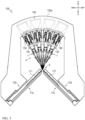
FIG. 1 is a side view illustrating a flat knitting machine according to a first embodiment of the disclosure; -
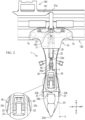
FIG. 2 is a schematic of a yarn passage rail and a yarn feeder, in a view along arrow A inFIG. 1 ; -
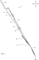
FIG. 3 is a side view of a yarn feeder; -
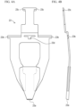
FIG. 4A is a front view illustrating a yarn feeder portion;FIG. 4B is a side view illustrating the yarn feeder portion; -
FIG. 5 is a cross-sectional view taken along line C-C inFIG. 2 ; -
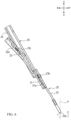
FIG. 6 is an enlarged side sectional view illustrating the yarn feeder having the feeder tip raised; -
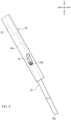
FIG. 7 is an enlarged side sectional view of a yarn feeder included in a flat knitting machine according to a second embodiment of the disclosure; -
FIG. 8 is an enlarged side sectional view of the yarn feeder having the feeder tip raised, in the second embodiment; -
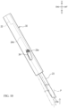
FIG. 9 is an enlarged side sectional view of a yarn feeder included in a flat knitting machine according to a third embodiment of the disclosure; and -
FIG. 10 is an enlarged side sectional view of the yarn feeder having the feeder tip raised, in the third embodiment. - In the following description, the directions indicated by arrows U, D, F, B, L, and R in the drawings are defined as an upward direction, a downward direction, a frontward direction, a backward direction, a leftward direction, and a rightward direction, respectively.
- As illustrated in
FIGS. 1 and2 , aflat knitting machine 100 according to a first embodiment of the disclosure mainly includeneedle beds 110,carriages 120,yarn passage rails 130, and up-downactuating mechanisms 140. - The
needle beds 110 are disposed facing each other, with a needle bed gap S therebetween, in the front-back direction. The front andrear needle beds 110 are disposed in an inverted V shape in side view, with each of theneedle beds 110 positioned diagonally upwards toward the center between theneedle beds 110 in the front-back direction (in the direction facing each other). Each of theneedle beds 110 is provided with a large number of knittingneedles 111 that are arranged in the longitudinal direction (left-right direction) of theneedle bed 110. - The
carriage 120 is disposed as a pair, on the front and rear sides, respectively, in a manner facing the front andrear needle beds 110, respectively, from above. The front andrear carriages 120 are connected to each other via agate arm 120a disposed in a manner straddling over the plurality ofyarn passage rails 130. Thecarriages 120 are enabled to reciprocate in the longitudinal direction of theneedle beds 110 by a servo motor (not illustrated). Each of thecarriages 120 is provided with a needle selecting mechanism (not illustrated) and a cam mechanism (not illustrated) for causing theknitting needles 111 on theneedle beds 110 to selectively operate. - A plurality of the
yarn passage rails 130 stretch above theneedle beds 110, and are disposed in a manner extending along the longitudinal direction of theneedle beds 110. Theyarn passage rails 130 are arranged radially with respect to the center between the front andrear needle beds 110 in side view. The "center between the front andrear needle beds 110" herein means the position where the yarn is fed, in side view. On the front and rear surfaces of each of theyarn passage rails 130,yarn feeders 1 for feeding knitting yarn are supported, respectively, in a manner movable along theyarn passage rail 130, as a part of a path for feeding the knitting yarn to the knittingneedle 111. The knitting yarn from a yarn package (not illustrated) is fed to theyarn feeders 1 via an appropriate yarn feed path. - Each of the up-down
actuating mechanisms 140 includes acam plate 141 provided above the correspondingyarn feeder 1, and enabled to push down thefeeder rod 20 of theyarn feeder 1. Thefeeder rod 20 is lowered by causing thecam plate 141 to operate. The up-downactuating mechanism 140 also includes aspring 142 that is inserted onto the raisingbias unit 21, which will be described later, and applies an upward biasing force to thefeeder rod 20. The up-downactuating mechanism 140 is thus enabled to raise thefeeder rod 20, with thespring 142. - A configuration of the
yarn feeder 1 will now be described with reference toFIGS. 2 to 6 . Among the plurality ofyarn feeders 1,FIGS. 2 ,3 ,5 , and6 illustrate therearmost yarn feeder 1. - The
yarn feeder 1 is enabled to travel along theyarn passage rail 130, in the longitudinal direction of theyarn passage rail 130, by being provided with travellingrollers 1a. With a belt fixed to theyarn feeder 1, theyarn feeder 1 is enabled to travel by causing a motor to drive the belt. Theyarn feeder 1 may also be configured to travel by being pulled by thecarriage 120. - Each of the
yarn feeders 1 includes acarrier base 10, afeeder rod 20, and afeeder rod guide 30. - The
carrier base 10 illustrated inFIGS. 2 and3 is for supporting thefeeder rod 20 and thefeeder rod guide 30, which will be described later. Thecarrier base 10 is provided as an upper part of theyarn feeder 1. As illustrated inFIG. 2 , thecarrier base 10 is provided with a raising biasunit guiding groove 11, which is an example of the guiding means according to the disclosure. The raising biasunit guiding groove 11 is provided at the center of thecarrier base 10, being the center in the left-right direction, in a manner extending in the up-down direction, and is enabled to guide the raisingbias unit 21 of thefeeder rod 20, which will be described later. - The
feeder rod 20 is moved up or down to prevent collisions of thefeeder tips 23a for feeding the knitting yarn to the knitting needles 111. Thefeeder rod 20 is supported on thecarrier base 10, and thefeeder rods 20 of therespective yarn feeders 1 are provided radially with respect to the center between the front andrear needle beds 110 in side view. Each of thefeeder rods 20 includes the raisingbias unit 21, therod 22, theyarn feeder portion 23, and acoupling plate 24. - The raising
bias unit 21 illustrated inFIGS. 2 and3 is provided to an upper part of thefeeder rod 20. Thespring 142 of the up-downactuating mechanism 140 is inserted onto and attached to the raisingbias unit 21. The raisingbias unit 21 thus receives the upward biasing force of thespring 142. At the same time, the raisingbias unit 21 is pressed downwards by thecam plate 141, which is of the up-downactuating mechanism 140, via a press-downportion 21a provided to an upper part of the raisingbias unit 21. The raisingbias unit 21 extends in a direction in which the raising biasunit guiding groove 11 extends, and is actuated by the up-downactuating mechanism 140 to move up or down by being guided along the raising biasunit guiding groove 11. - The
rod 22 illustrated inFIGS. 2 and3 is provided under the raisingbias unit 21, and provided in a manner extending linearly in the direction in which the raisingbias unit 21 extends. Therod 22 is connected to the raisingbias unit 21, and is actuated by the up-downactuating mechanism 140 to move up or down together with the raisingbias unit 21. Aprotrusion 22a protruding backwards is provided to a lower part of therod 22. - The
yarn feeder portion 23 is disposed below therod 22, and thefeeder tip 23a is provided to the bottom end of theyarn feeder portion 23. The position where thefeeder tip 23a is disposed is not limited to the bottom end of theyarn feeder portion 23. Theyarn feeder portion 23 is a member separate from therod 22, and is connected to therod 22 via thecoupling plate 24, which will be described later. By connecting theyarn feeder portion 23 and therod 22 via thecoupling plate 24, theyarn feeder portion 23 is connected movably to therod 22. When theyarn feeder portion 23 is moved with respect to therod 22, thefeeder tip 23a moves in a direction in which the position of thefeeder tip 23a with respect to therod 22 in the front-back direction changes, in a direction different from the guide direction in which thefeeder rod 20 is moved up or down by the up-downactuating mechanism 140 by being guided along the raising biasunit guiding groove 11. Theyarn feeder portion 23 has a feeder tipside guide runner 23b and a carrier baseside guide runner 23c. - The feeder tip
side guide runner 23b illustrated inFIGS. 2 ,4 , and5 is guided along feeder tipside guiding grooves 31a, which will be described later. The feeder tipside guide runner 23b is provided in a middle portion of theyarn feeder portion 23 in the vertical direction, in a manner protruding toward the left and the right, at a position above thefeeder tip 23a. The feeder tipside guide runner 23b has a rectangular or a rhombus shape with its two opposing corners chamfered, in side view, so that theyarn feeder portion 23 is permitted to move in a direction different from the guide direction in which therod 22 is guided by the raising biasunit guiding groove 11. The feeder tipside guide runner 23b may also have a circular shape or an elliptical shape in side view. - The carrier base
side guide runner 23c illustrated inFIGS. 2 ,4 , and5 is guided along carrier baseside guiding grooves 32a, which will be described later. The carrier baseside guide runner 23c has a shape protruding toward the left and the right sides from the top end of theyarn feeder portion 23, at a position higher than the feeder tipside guide runner 23b. The carrier baseside guide runner 23c has a rectangular shape or a rhombus shape with its two opposing corners chamfered, in side view. The carrier baseside guide runner 23c may also have a circular shape or an elliptical shape in side view. - The
coupling plate 24 is disposed between therod 22 and theyarn feeder portion 23, and couples therod 22 and theyarn feeder portion 23. Thecoupling plate 24 includes a feeder tip position adjustingelongated hole 24a and abottom end connector 24b. - The feeder tip position adjusting
elongated hole 24a illustrated inFIG. 2 is an example of the feeder tip height adjusting means according to the disclosure, and is provided in a manner penetrating thecoupling plate 24 in the thickness direction, and in a manner extending in the longitudinal direction of thecoupling plate 24. The feeder tip position adjustingelongated hole 24a is provided to an upper part of thecoupling plate 24. Into this feeder tip position adjustingelongated hole 24a, theprotrusion 22a of therod 22 is inserted from the front side. With theprotrusion 22a inserted into the feeder tip position adjustingelongated hole 24a, the left-right position of thecoupling plate 24 with respect to therod 22 is restricted. Ascrew 40 is then inserted into the feeder tip position adjustingelongated hole 24a from the back, at a position lower than theyarn passage rail 130. Thescrew 40 is then screwed into a female screw hole (not illustrated) provided to a lower part of therod 22. In this manner, thecoupling plate 24 is fixed to therod 22, in an upper part of thecoupling plate 24. - The
bottom end connector 24b illustrated inFIG. 2 is provided to the bottom end of thecoupling plate 24, and is engaged with anengagement hole 23d (seeFIGS. 4A and 4B ) provided to theyarn feeder portion 23. Thecoupling plate 24 is thus connected to theyarn feeder portion 23 via the lower part of thecoupling plate 24 in such a manner that theyarn feeder portion 23 is movable in a direction in which the position of theyarn feeder portion 23 in the front-back direction changes. - The
feeder rod guide 30 is provided in front of thefeeder rod 20, and is for guiding thefeeder rod 20. Thefeeder rod guide 30 has its upper end portion supported by thecarrier base 10. Thefeeder rod guide 30 includes feeder tip side guides 31 and a carrierbase side guide 32. - The feeder tip side guides 31 and the feeder tip
side guide runner 23b are an example of converting means according to the disclosure. The feeder tip side guides 31 are provided to the left and right sides of the bottom end of thefeeder rod guide 30, respectively. The feeder tip side guides 31 extend in parallel with the path along which therod 22 is advanced and evacuated. As illustrated inFIG. 5 , each of the feeder tip side guides 31 has a feeder tipside guiding groove 31a. The feeder tipside guiding grooves 31a are provided in a manner recessed outwards on the left and right sides of thefeeder rod guide 30, respectively, and each of feeder tipside guiding grooves 31a has openings on the top end and the bottom end of the feedertip side guide 31, respectively. The feeder tipside guide runner 23b is housed in the feeder tip side guides 31. - The carrier
base side guide 32 and the carrier baseside guide runner 23c are one example of the converting means according to the disclosure. The carrier base side guides 32 are provided at a position higher than the feeder tip side guides 31. - The carrier
base side guide 32 is provided in a manner extending in a direction different from the trajectory along which therod 22 is advanced and evacuated by the up-downactuating mechanism 140. More specifically, as illustrated inFIGS. 3 ,5 , and6 , the carrierbase side guide 32 is provided in a manner extending in a direction closer to the horizontal direction than the guide direction in which therod 22 is guided by the raising biasunit guiding groove 11. - As illustrated in
FIGS. 5 and6 , the carrierbase side guide 32 has a carrier baseside guiding groove 32a. The carrier baseside guiding groove 32a has an opening on the bottom end of the carrierbase side guide 32, and extends in parallel with the direction in which the carrierbase side guide 32 extends. The carrier baseside guide runner 23c is housed in the carrier baseside guiding grooves 32a. With this configuration, when the height of thefeeder tip 23a is to be moved up, the carrier baseside guide runner 23c is guided along the carrierbase side guide 32 in a direction inclined toward the side on which the upper end of theyarn feeder portion 23 moves away from the needle bed gap S in the front-back direction than the longitudinal direction of therod 22. - In the
yarn feeder 1 having the configuration described above, by having theyarn feeder portion 23 guided by the feeder tip side guides 31 and the carrierbase side guide 32 of thefeeder rod guide 30, theyarn feeder portion 23 is movably connected to therod 22 in a direction in which the position of theyarn feeder portion 23 with respect to therod 22 in the front-back direction changes, in a direction different from the guide direction in which therod 22 is guided by the raising biasunit guiding groove 11. - More specifically, the feeder
tip side guide 31 and the carrierbase side guide 32 convert, at least within a yarn feedable range, the moving direction of thefeeder tip 23a to a direction bringing the moving direction of thefeeder tip 23a closer to the vertical direction, than the guide direction in which therod 22 is guided by the raising biasunit guiding groove 11, in response to a change in the height of thefeeder tip 23a, having been changed by the up-downactuating mechanism 140, or by a change in the position where thescrew 40 is fastened in the feeder tip position adjustingelongated hole 24a in the longitudinal direction. The "yarn feedable range" herein means a range of heights at which thefeeder tip 23a can be feed yarn to a position at which the yarn is taken hold of. - A way in which the
feeder rod 20 is advanced and evacuated with respect to the needle bed gap S will be described below with reference toFIGS. 1 and2 . When theyarn feeder 1 performs a yarn-feeding operation, thecam plate 141 presses down the press-downportion 21a provided to the upper part of the raisingbias unit 21, and the raisingbias unit 21 is caused to lower, against the biasing force of thespring 142, by being guided along the raising biasunit guiding groove 11. As the raisingbias unit 21 is lowered, therod 22 is lowered, and thefeeder tip 23a of theyarn feeder portion 23 goes into the needle bed gap S. By causing thefeeder tip 23a to go into the needle bed gap S, theyarn feeder portion 23 is enabled to feed the knitting yarn to theknitting needle 111. - While the
yarn feeder 1 is to be put to standby, thecam plate 141 releases the pressing force on the press-downportion 21a. Once thecam plate 141 releases the pressing force on the press-downportion 21a, thefeeder rod 20 is raised by the biasing force of thespring 142, and theyarn feeder portion 23 is evacuated from the needle bed gap S. By causing thefeeder tip 23a of theyarn feeder 1 not feeding yarn to evacuate from the needle bed gap S, it is possible to alleviate the collision of theyarn feeder portion 23 of theyarn feeder 1 feeding yarn with theyarn feeder portion 23 of theyarn feeder 1 not feeding yarn. - The way in which the height of the
feeder tip 23a is adjusted will now be described. In theyarn feeder 1, the yarn-feeding height of thefeeder tip 23a can be adjusted, depending on the knitting condition. When the height of thefeeder tip 23a is to be adjusted, the position where thescrew 40 is fastened in the longitudinal direction of the feeder tip position adjustingelongated hole 24a is adjusted, to adjust the up-down position of thecoupling plate 24 with respect to therod 22. By adjusting the up-down position of thecoupling plate 24 with respect to therod 22, the height of thefeeder tip 23a can be adjusted. - The
rod 22 and thecoupling plate 24 are fastened by thescrew 40 below theyarn passage rail 130. Hence, it is possible to adjust the height of thecoupling plate 24 with respect to therod 22 by avoiding theyarn passage rail 130. Therefore, it is possible to adjust the yarn-feeding height of thefeeder tip 23a, easily. - If the
yarn feeder portion 23 is moved in the same direction as the guide direction in which therod 22 is guided by the raising biasunit guiding groove 11 in order to adjust the yarn-feeding height of thefeeder tip 23a in a manner suitable for the knitting condition, thefeeder tip 23a becomes displaced from a center plane between the front andrear needle beds 110. As a result, when thefeeder tip 23a is moved up or down, thefeeder tip 23a may move out of the region where thefeeder tip 23a can feed yarn to the target position that is on the side of the needle bed gap S, the target position being a position where a knitting needle takes hold of the yarn. - Furthermore, for plating knitting in which the knitting yarns of two
yarn feeders 1 are knitted simultaneously by advancing and evacuating thefeeder rods 20 with respect to the needle bed gap S, it becomes possible to set the position of thefeeder tip 23a higher foryarn feeder 1 for plating, which is kept delayed from theordinary yarn feeder 1, so that the knitting can be carried out with the main yarn and the plating yarn at difference heights. In this manner, when thefeeder tip 23a is moved up or down by an advancing or evacuating movement of thefeeder rod 20, too, thefeeder tip 23a may move in a direction separating from the region where thefeeder tip 23a can feed yarn to the target position that is on the side of the needle bed gap S. - Therefore, in the
flat knitting machine 100 according to the present embodiment, the configurations such as the feedertip side guide 31 and the carrierbase side guide 32 serve to suppress the displacement of thefeeder tip 23a in the front-back direction, accompanying the up or down movement of as thefeeder tip 23a. An operation of theyarn feeder portion 23 when thefeeder tip 23a is moved upwards for the yarn-feeding operation will now be described with reference mainly toFIGS. 5 and6 .FIG. 5 illustrates a configuration before thefeeder tip 23a is raised.FIG. 6 illustrates a configuration after thefeeder tip 23a is raised from the configuration illustrated inFIG. 5 . - When the up-down
actuating mechanism 140 rises therod 22, theyarn feeder portion 23 also moves upwards while being guided by thefeeder rod guide 30. Furthermore, when the position ofcoupling plate 24 with respect to therod 22 is shifted upwards by shifting the feeder tip position adjustingelongated hole 24a upwards with respect to thescrew 40, theyarn feeder portion 23 also moves upwards while being guided by thefeeder rod guide 30. - More specifically, the
yarn feeder portion 23 is raised from the position illustrated inFIG. 5 to the position illustrated inFIG. 6 , for example, while the feeder tipside guide runner 23b is guided along the feeder tipside guiding grooves 31a of the feedertip side guide 31, and while the carrier baseside guide runner 23c of theyarn feeder portion 23 is guided along the carrier baseside guiding groove 32a of the carrierbase side guide 32. When the feeder tipside guide runner 23b is guided along the feeder tipside guiding grooves 31a on the feedertip side guide 31, the feeder tipside guide runner 23b follows a trajectory in parallel with the trajectory of therod 22 actuated by the up-downactuating mechanism 140. By contrast, the carrier baseside guiding groove 32a of the carrierbase side guide 32 is configured in such a manner that the carrier baseside guide runner 23c is guided in a direction inclined with respect to the longitudinal direction of therod 22, being inclined toward the side on which the upper end of the carrier baseside guiding groove 32a moves away from the needle bed gap S in the front-back direction. Therefore, as theyarn feeder portion 23 is moved upwards, the inclination of theyarn feeder portion 23 changes in the direction becoming closer to the horizontal direction. - When the inclination of the
yarn feeder portion 23 changes in a direction becoming closer to the horizontal direction, thefeeder tip 23a moves substantially in the vertical direction, without becoming displaced to the side of therear needle bed 110 in the front-back direction. In this manner, thefeeder tip 23a can be raised while suppressing the displacement of thefeeder tip 23a in the front-back direction, with respect to the center plane P between the front andrear needle beds 110. The center plane P herein is a vertical plane passing through the center between the front andrear needle beds 110 in the front-back direction. In the same manner, thefeeder tip 23a can be lowered from the position illustrated inFIG. 5 to the position illustrated inFIGS. 4A and 4B , for example, while suppressing the displacement of thefeeder tip 23a in the front-back direction, with respect to the center plane P between the front andrear needle beds 110. - In the manner described above, it is possible to suppress the displacement of the
feeder tip 23a from the center plane P between the front andrear needle beds 110, when thefeeder tip 23a is moved up or down. Therefore, it is possible to suppress a movement of thefeeder tip 23a in a direction separating from the region where the feeder tip can feed yarn to the target position that is on the side of the needle bed gap S, when thefeeder tip 23a is moved up or down. - A
flat knitting machine 100 according to a second embodiment of the disclosure will be described below with reference toFIGS. 7 and8 . The same components as those of the first embodiment are denoted by the same reference numerals, and descriptions thereof will be omitted. - The
flat knitting machine 100 according to the second embodiment is different from theflat knitting machine 100 according to the first embodiment in that thefeeder rod guide 30 includes a carrierbase side guide 33, instead of the carrierbase side guide 32. - In the same manner as the carrier
base side guide 32, a lower part of the carrierbase side guide 33 extends in a direction becoming closer to the horizontal direction than the guide direction in which therod 22 is guided by the raising biasunit guiding groove 11. An upper part of the carrierbase side guide 33 is bent in a manner extending in a direction becoming nearer to the vertical direction than the direction in which the lower part of the carrierbase side guide 33 extends, at a position at which the height of thefeeder tip 23a is brought above the yarn feedable range. The carrierbase side guide 33 has a carrier baseside guiding groove 33a having a shape corresponding to the carrierbase side guide 33. The carrier baseside guide runner 23c is housed in the carrier baseside guiding grooves 33a. - When the
rod 22 is raised by the up-downactuating mechanism 140, or when the feeder tip position adjustingelongated hole 24a is shifted upwards with respect to thescrew 40, theyarn feeder portion 23 rises from the position illustrated inFIG. 7 to the position illustrated inFIG. 8 , for example, while the feeder tipside guide runner 23b is guided along the feeder tipside guiding groove 31a of the feedertip side guide 31, and the carrier baseside guide runner 23c of theyarn feeder portion 23 is guided along the carrier baseside guiding groove 33a of the carrierbase side guide 33. With the carrier base side guides 33, thefeeder tip 23a moves vertically within the yarn feedable range. By contrast, when thefeeder tip 23a is raised while thefeeder tip 23a is above the yarn feedable range, more specifically, when the carrier baseside guide runner 23c is at a position higher than the bent part of the carrierbase side guide 33, thefeeder tip 23a moves in a direction separating from the needle bed gap S in the front-back direction. Therefore, collisions between theyarn feeder portions 23 can be further suppressed. - A
flat knitting machine 100 according to a third embodiment of the disclosure will be described below with reference toFIGS. 9 and10 . The same components as those of the first embodiment are denoted by the same reference numerals, and descriptions thereof will be omitted. - The
flat knitting machine 100 according to the third embodiment is different from theflat knitting machine 100 according to the first embodiment in that thefeeder rod 20 includes an elastically deformingportion 24A, instead of thecoupling plate 24; theyarn feeder portion 23 has aprotrusion 23e; and thefeeder rod guide 30 has an elongatedguide hole 34, instead of the feedertip side guide 31 and the carrierbase side guide 32. - The elastically deforming
portion 24A that is elastically deformable is provided between therod 22 and theyarn feeder portion 23. Therod 22, theyarn feeder portion 23, and the elastically deformingportion 24A are integrally formed. Aprotrusion 23e protruding in the left-right direction is formed on an upper part of theyarn feeder portion 23. - The
elongated guide hole 34 of thefeeder rod guide 30 extends in a direction closer to the vertical direction than the guide direction in which therod 22 is guided by the raising biasunit guiding groove 11. Theprotrusion 23e is inserted into theelongated guide hole 34. - When the
rod 22 is raised by the up-downactuating mechanism 140, theprotrusion 23e moves from the bottom end of theelongated guide hole 34 to the upper end thereof, by being guided along theelongated guide hole 34. With this, theyarn feeder portion 23 is raised from the position illustrated inFIG. 9 to the position illustrated inFIG. 10 , for example. By guiding theprotrusion 23e along theelongated guide hole 34, and with the elastic force of the elastically deformingportion 24A, the inclination of theyarn feeder portion 23 is changed in a direction closer to the horizontal direction, as theyarn feeder portion 23 is moved upwards. Within the yarn feedable range, thefeeder tip 23a moves in a vertical direction, as theprotrusion 23e is guided along theelongated guide hole 34. - Because there is no
coupling plate 24 in the third embodiment, the feeder tip position adjustingelongated hole 24a is provided to a member provided between the upper part and the lower part of therod 22. The height of thefeeder tip 23a can be adjusted by adjusting the height of the lower part of therod 22 with respect to the height of the upper part of therod 22. - As described above, in each of the embodiments, it is possible to move the
feeder tip 23a up or down while suppressing the displacement of thefeeder tip 23a from the center plane P between the front andrear needle beds 110, in the front-back direction. The center plane P herein is a vertical plane passing through the center between the front andrear needle beds 110 in the front-back direction. It is therefore possible to suppress the movement of thefeeder tip 23a in a direction separating from the region where the feeder tip can feed yarn to the target position that is on the side of the needle bed gap S, as thefeeder tip 23a is moved up or down. - Although each of the embodiments of the disclosure has been described above, the disclosure is not limited to the embodiments described above, and appropriate modifications may be made within the scope of the technical idea of the invention described in the claims.
- For example, the converting means including the feeder
tip side guide 31, the feeder tipside guide runner 23b, the carrierbase side guide 32, and the carrier baseside guide runner 23c are applicable, regardless of how the yarn passage rails 130 are disposed. The yarn passage rails 130 are not limited to those arranged radially with respect to the center between the front andrear needle beds 110 in side view, and may also be those arranged horizontally, as described inFIGS. 4(b) and 4(c) ofEP 3115491 Al, for example. In the case where the yarn passage rails 130 are provided in this manner, while thefeeder rods 20 move up or down in the vertical directions, each of thefeeder rods 20 has a bent portion bent toward the needle bed gap S so that theyarn feeder portion 23 of eachfeeder rod 20 can feed the yarn thereto. The converting means including the feedertip side guide 31, the feeder tipside guide runner 23b, the carrierbase side guide 32, and the carrier baseside guide runner 23c is also applicable to the case where the feeder tip height adjusting means, such as the feeder tip position adjustingelongated hole 24a, is provided to a portion lower than the bent portion. In this case, theyarn feeder portion 23 is advanced or evacuated along this portion below the bent portion, following the guiding means. - Furthermore, the direction in which the
feeder tip 23a is moved by the converting means including the feedertip side guide 31, the feeder tipside guide runner 23b, the carrierbase side guide 32, and the carrier baseside guide runner 23c does not need to be exactly the vertical direction, and the direction may be a direction closer to the vertical direction than the guide direction in which therod 22 is guided by the raising biasunit guiding groove 11. - In addition, the up-down
actuating mechanism 140 is not limited to the one that uses thecam plate 141 to move thefeeder rod 20 up or down, and may be one that uses an actuating lever to move thefeeder rod 20 up or down, or one that uses a rack and pinion to move thefeeder rod 20 up or down, as described inJP 2012 -524842 W - The feeder tip height adjusting means for adjusting the height of the
feeder tip 23a at the time of feeding yarn has been described to adjust the height of thefeeder tip 23a at the time of feeding yarn by changing the position where thescrew 40 is fastened, in the longitudinal direction of the feeder tip position adjustingelongated hole 24a. However, the feeder tip height adjusting means may also use a motor to adjust the height of thecam plate 141, as disclosed inCN 210711959 U , for example, to adjust the yarn-feeding height of thefeeder tip 23a. - The
flat knitting machine 100 is not necessarily required to be provided with the up-downactuating mechanism 140 for moving thefeeder rod 20 up or down. In such a configuration, theyarn feeder portion 23 is not necessarily required to be connected to therod 22, and theyarn feeder portion 23 may be connected to thefeeder rod guide 30. - In the first embodiment, the
feeder rod 20 is provided with the runners (the feeder tipside guide runner 23b and the carrier baseside guide runner 23c), and thefeeder rod guide 30 is provided with the guiding grooves (the feeder tipside guiding groove 31a and the carrier baseside guiding groove 33a). However, it is also possible for thefeeder rod guide 30 to be provided with the runners, and thefeeder rod 20 may be provided with the guiding grooves. In such a configuration, the guiding grooves may be provided on the side surfaces of theyarn feeder portion 23. -
- 1
- yarn feeder
- 10
- carrier base
- 20
- feeder rod
- 22
- rod
- 23
- yarn feeder portion
- 23a
- feeder tip
- 23b
- feeder tip side guide runner
- 23c
- carrier base side guide runner
- 24
- coupler
- 24a
- feeder tip position adjusting elongated hole
- 30
- feeder rod guide
- 31
- feeder tip side guide
- 32, 33
- carrier base side guide
- 34
- elongated guide hole
- 40
- screw
- 100
- flat knitting machine
- 110
- needle bed
- 111
- knitting needle
- 130
- yarn passage rail
Claims (6)
- A flat knitting machine (100), comprising:at least two needle beds (110) that face each other with a needle bed gap (S) therebetween, and each of which has knitting needles (111) arranged side by side in a longitudinal direction;a yarn passage rail (130) that is installed above the needle beds (110);a carrier base (10) that is provided movably along the yarn passage rail (130);a yarn feeder (1) that is provided as a part of a path for feeding knitting yarn to the knitting needles (111), the yarn feeder (1) including the carrier base (10) and a feeder tip (23a) for feeding the knitting yarn to the knitting needles (111); andfeeder tip height adjusting means (24a, 40) for adjusting a yarn-feeding height of the feeder tip (23a), the flat knitting machine (100) being characterized in that:the yarn feeder (1) includes:a feeder rod (20) to which the feeder tip (23a) is provided;converting means (23b, 23c, 31, 32, 33, 34) for converting a direction in which the feeder tip (23a) is moved;a feeder rod guide (30) that is supported by the carrier base (10) and that supports the converting means (23b, 23c, 31, 32, 33, 34); andguiding means (11) for guiding the feeder rod (20) in a guide direction that is inclined with respect to a vertical direction,the converting means (23b, 23c, 31, 32, 33, 34) is included in the feeder rod (20) and the feeder rod guide (30), and converts the direction in which the feeder tip (23a) is moved, to a direction bringing the feeder tip (23a) closer to the vertical direction than the guide direction, in response to a change in a height of the feeder tip (23a), at least within a height range where the feeder tip (23a) is allowed to feed the yarn to a position at which the yarn is taken hold of.
- The flat knitting machine (100) according to claim 1, characterized in that:the feeder rod (20) is provided with a yarn feeder portion (23) that is provided with the feeder tip (23a), andthe converting means (23b, 23c, 31, 32, 33, 34) includes:a feeder tip side guide runner (23b) provided to any one of the yarn feeder portion (23) or the feeder rod guide (30), on a side closer to the feeder tip (23a);a carrier base side guide runner (23c) provided to any one of the yarn feeder portion (23) or the feeder rod guide (30), on a side closer to the carrier base (10);a feeder tip side guide (31) provided to the other one of the yarn feeder portion (23) and the feeder rod guide (30), on the side closer to the feeder tip (23a), and adapted to guide the feeder tip side guide runner (23b) along a trajectory in parallel with the guide direction; anda carrier base side guide (32, 33) provided to the other one of the yarn feeder portion (23) and the feeder rod guide (30), on the side closer to the carrier base (10), and adapted to guide the carrier base side guide runner (23c) in a direction inclined with respect to the guide direction, being inclined toward a side on which an upper end of the yarn feeder portion (23) moves away from the needle bed gap (S) in a front-back direction.
- The flat knitting machine (100) according to claim 1, characterized in that the feeder rod (20) includes:a rod (22) that is guided in the guide direction by the guiding means (11), and that is moved up and down by being actuated by an up-down actuating mechanism (140); anda yarn feeder portion (23) that is connected to the rod (22) and that is provided with the feeder tip (23a).
- The flat knitting machine (100) according to claim 3, characterized in that the yarn feeder portion (23) is a member separate from the rod (22), and the feeder tip (23a) is connected to the rod (22) in a manner movable in a direction different from the guide direction of the feeder rod (20), and in a direction in which the position of the feeder tip (23a) with respect to the rod (22) changes in the front-back direction.
- The flat knitting machine (100) according to claim 3 or 4, characterized in thatthe feeder rod (20) includes a coupler (24) disposed between the rod (22) and the yarn feeder portion (23), and coupling the rod (22) and the yarn feeder portion (23), andthe coupler (24) is fixed and connected to the rod (22) at a position below the yarn passage rail (130) in such a manner that the feeder tip height adjusting means (24a, 40) can adjust an up-down position with respect to the rod (22).
- The flat knitting machine (100) according to claim 3 or 4, characterized in thatthe guiding means (11) is provided to the carrier base (10), andthe yarn passage rail (130) is provided radially with respect to the center between the needle beds (110) that are on a front side and a back side in a side view.
Applications Claiming Priority (1)
| Application Number | Priority Date | Filing Date | Title |
|---|---|---|---|
| JP2023073548A JP7811192B2 (en) | 2023-04-27 | 2023-04-27 | flat knitting machine |
Publications (2)
| Publication Number | Publication Date |
|---|---|
| EP4455379A1 true EP4455379A1 (en) | 2024-10-30 |
| EP4455379B1 EP4455379B1 (en) | 2025-09-10 |
Family
ID=90826373
Family Applications (1)
| Application Number | Title | Priority Date | Filing Date |
|---|---|---|---|
| EP24171573.9A Active EP4455379B1 (en) | 2023-04-27 | 2024-04-22 | Flat knitting machine |
Country Status (4)
| Country | Link |
|---|---|
| EP (1) | EP4455379B1 (en) |
| JP (1) | JP7811192B2 (en) |
| KR (1) | KR20240158827A (en) |
| CN (1) | CN118854537B (en) |
Citations (7)
| Publication number | Priority date | Publication date | Assignee | Title |
|---|---|---|---|---|
| GB878691A (en) * | 1957-08-20 | 1961-10-04 | Coop Wholesale | Improvements in or relating to flat bar knitting machines |
| EP0898002A2 (en) * | 1997-08-21 | 1999-02-24 | Shima Seiki Manufacturing, Ltd. | A flat knitting machine having a yarn feeding system |
| US20080302137A1 (en) * | 2004-07-07 | 2008-12-11 | Masaki Miyamoto | Yarn Feeder of Yarn Feeding Device for Weft Knitting Machine |
| EP2243871B1 (en) * | 2009-04-23 | 2012-05-23 | H. Stoll GmbH & Co. KG | Flat knitting machine with at least one mobile thread guide moved along a thread rail |
| EP3115491A1 (en) | 2015-07-09 | 2017-01-11 | H. Stoll GmbH & Co. KG | Flat knitting machine |
| CN210711959U (en) | 2019-09-23 | 2020-06-09 | 江苏金龙科技股份有限公司 | Double-motor yarn nozzle switcher |
| US20200270782A1 (en) * | 2019-02-27 | 2020-08-27 | Pai Lung Machinery Mill Co., Ltd. | Flat knitting machine yarn feeder with variable yarn feeding positions |
Family Cites Families (6)
| Publication number | Priority date | Publication date | Assignee | Title |
|---|---|---|---|---|
| JP2807848B2 (en) * | 1991-07-11 | 1998-10-08 | 株式会社島精機製作所 | Driving device for yarn feeder in flat knitting machine |
| JP3044370U (en) | 1997-06-13 | 1997-12-22 | 景山産業株式会社 | Weights for fishing |
| CN101278086B (en) * | 2005-09-28 | 2010-12-08 | 株式会社岛精机制作所 | Flat knitting machine with movable yarn guide |
| JP4965913B2 (en) * | 2006-06-30 | 2012-07-04 | 株式会社島精機製作所 | Knitting yarn retracting method and flat knitting machine |
| JP2008156786A (en) * | 2006-12-25 | 2008-07-10 | Shima Seiki Mfg Ltd | Tension device for knitting yarn in flat knitting machine |
| JP5543780B2 (en) * | 2007-09-07 | 2014-07-09 | 株式会社島精機製作所 | Flat knitting machine and its yarn feeding method |
-
2023
- 2023-04-27 JP JP2023073548A patent/JP7811192B2/en active Active
-
2024
- 2024-04-22 EP EP24171573.9A patent/EP4455379B1/en active Active
- 2024-04-26 KR KR1020240055976A patent/KR20240158827A/en active Pending
- 2024-04-26 CN CN202410512940.2A patent/CN118854537B/en active Active
Patent Citations (8)
| Publication number | Priority date | Publication date | Assignee | Title |
|---|---|---|---|---|
| GB878691A (en) * | 1957-08-20 | 1961-10-04 | Coop Wholesale | Improvements in or relating to flat bar knitting machines |
| EP0898002A2 (en) * | 1997-08-21 | 1999-02-24 | Shima Seiki Manufacturing, Ltd. | A flat knitting machine having a yarn feeding system |
| JP3044370B2 (en) | 1997-08-21 | 2000-05-22 | 株式会社島精機製作所 | Yarn supply device in flat knitting machine |
| US20080302137A1 (en) * | 2004-07-07 | 2008-12-11 | Masaki Miyamoto | Yarn Feeder of Yarn Feeding Device for Weft Knitting Machine |
| EP2243871B1 (en) * | 2009-04-23 | 2012-05-23 | H. Stoll GmbH & Co. KG | Flat knitting machine with at least one mobile thread guide moved along a thread rail |
| EP3115491A1 (en) | 2015-07-09 | 2017-01-11 | H. Stoll GmbH & Co. KG | Flat knitting machine |
| US20200270782A1 (en) * | 2019-02-27 | 2020-08-27 | Pai Lung Machinery Mill Co., Ltd. | Flat knitting machine yarn feeder with variable yarn feeding positions |
| CN210711959U (en) | 2019-09-23 | 2020-06-09 | 江苏金龙科技股份有限公司 | Double-motor yarn nozzle switcher |
Also Published As
| Publication number | Publication date |
|---|---|
| JP2024158391A (en) | 2024-11-08 |
| CN118854537B (en) | 2026-04-28 |
| CN118854537A (en) | 2024-10-29 |
| KR20240158827A (en) | 2024-11-05 |
| JP7811192B2 (en) | 2026-02-04 |
| EP4455379B1 (en) | 2025-09-10 |
Similar Documents
| Publication | Publication Date | Title |
|---|---|---|
| US5345789A (en) | Apparatus for controlling displacement of yarn feeders | |
| US6021651A (en) | Flat knitting machine having a yarn feeding system | |
| KR100867140B1 (en) | Yarn feeder of flat knitting machine | |
| EP2894245B1 (en) | Flatbed knitting machine equipped with sinker device | |
| EP1764431B1 (en) | Yarn feeding device for weft knitting machine | |
| EP4455379B1 (en) | Flat knitting machine | |
| EP2423363B1 (en) | Weft knitting machine equipped with movable sinker | |
| EP0533414B1 (en) | Flat knitting machine | |
| CN114381853A (en) | Flat knitting machine | |
| CN110678593B (en) | Plating knitting method in flat knitting machine | |
| KR100469828B1 (en) | Thread guide device of flat knitting machine | |
| US7152435B2 (en) | Weft knitting machine having movable sinker | |
| US7380419B2 (en) | Movable sinker apparatus and sinker of weft knitting machine | |
| EP2392710B1 (en) | Flat knitting machine | |
| EP2415917B1 (en) | Compound needle for flatbed knitting machine | |
| CN114657684B (en) | Knitting cam for flat knitting machine or knitting machine | |
| EP3546629B1 (en) | Yarn feeder for flatbed knitting machine | |
| CN111793889B (en) | Flat knitting machine | |
| CN113622076A (en) | Knitting and yarn pressing mechanism of glove knitting machine | |
| CN220099326U (en) | Flat knitting machine with movable sinker | |
| KR200200976Y1 (en) | Selector working structure of flat knitting machine | |
| JP2024158391A5 (en) | ||
| EP3702503B1 (en) | Flat knitting machine stitch pressing device with position varying with gap size | |
| CN115142183A (en) | Needle selection device and method of flat knitting machine |
Legal Events
| Date | Code | Title | Description |
|---|---|---|---|
| PUAI | Public reference made under article 153(3) epc to a published international application that has entered the european phase |
Free format text: ORIGINAL CODE: 0009012 |
|
| STAA | Information on the status of an ep patent application or granted ep patent |
Free format text: STATUS: THE APPLICATION HAS BEEN PUBLISHED |
|
| AK | Designated contracting states |
Kind code of ref document: A1 Designated state(s): AL AT BE BG CH CY CZ DE DK EE ES FI FR GB GR HR HU IE IS IT LI LT LU LV MC ME MK MT NL NO PL PT RO RS SE SI SK SM TR |
|
| STAA | Information on the status of an ep patent application or granted ep patent |
Free format text: STATUS: REQUEST FOR EXAMINATION WAS MADE |
|
| 17P | Request for examination filed |
Effective date: 20250408 |
|
| GRAP | Despatch of communication of intention to grant a patent |
Free format text: ORIGINAL CODE: EPIDOSNIGR1 |
|
| STAA | Information on the status of an ep patent application or granted ep patent |
Free format text: STATUS: GRANT OF PATENT IS INTENDED |
|
| RIC1 | Information provided on ipc code assigned before grant |
Ipc: D04B 15/80 20060101ALI20250426BHEP Ipc: D04B 15/56 20060101ALI20250426BHEP Ipc: D04B 15/48 20060101ALI20250426BHEP Ipc: D04B 7/26 20060101AFI20250426BHEP |
|
| INTG | Intention to grant announced |
Effective date: 20250515 |
|
| GRAS | Grant fee paid |
Free format text: ORIGINAL CODE: EPIDOSNIGR3 |
|
| GRAA | (expected) grant |
Free format text: ORIGINAL CODE: 0009210 |
|
| STAA | Information on the status of an ep patent application or granted ep patent |
Free format text: STATUS: THE PATENT HAS BEEN GRANTED |
|
| AK | Designated contracting states |
Kind code of ref document: B1 Designated state(s): AL AT BE BG CH CY CZ DE DK EE ES FI FR GB GR HR HU IE IS IT LI LT LU LV MC ME MK MT NL NO PL PT RO RS SE SI SK SM TR |
|
| REG | Reference to a national code |
Ref country code: GB Ref legal event code: FG4D |
|
| REG | Reference to a national code |
Ref country code: CH Ref legal event code: EP |
|
| REG | Reference to a national code |
Ref country code: DE Ref legal event code: R096 Ref document number: 602024000619 Country of ref document: DE |
|
| REG | Reference to a national code |
Ref country code: IE Ref legal event code: FG4D |
|
| PG25 | Lapsed in a contracting state [announced via postgrant information from national office to epo] |
Ref country code: NO Free format text: LAPSE BECAUSE OF FAILURE TO SUBMIT A TRANSLATION OF THE DESCRIPTION OR TO PAY THE FEE WITHIN THE PRESCRIBED TIME-LIMIT Effective date: 20251210 |
|
| REG | Reference to a national code |
Ref country code: LT Ref legal event code: MG9D |
|
| PG25 | Lapsed in a contracting state [announced via postgrant information from national office to epo] |
Ref country code: FI Free format text: LAPSE BECAUSE OF FAILURE TO SUBMIT A TRANSLATION OF THE DESCRIPTION OR TO PAY THE FEE WITHIN THE PRESCRIBED TIME-LIMIT Effective date: 20250910 |
|
| REG | Reference to a national code |
Ref country code: NL Ref legal event code: MP Effective date: 20250910 |
|
| PG25 | Lapsed in a contracting state [announced via postgrant information from national office to epo] |
Ref country code: HR Free format text: LAPSE BECAUSE OF FAILURE TO SUBMIT A TRANSLATION OF THE DESCRIPTION OR TO PAY THE FEE WITHIN THE PRESCRIBED TIME-LIMIT Effective date: 20250910 |
|
| PG25 | Lapsed in a contracting state [announced via postgrant information from national office to epo] |
Ref country code: GR Free format text: LAPSE BECAUSE OF FAILURE TO SUBMIT A TRANSLATION OF THE DESCRIPTION OR TO PAY THE FEE WITHIN THE PRESCRIBED TIME-LIMIT Effective date: 20251211 |
|
| PG25 | Lapsed in a contracting state [announced via postgrant information from national office to epo] |
Ref country code: SE Free format text: LAPSE BECAUSE OF FAILURE TO SUBMIT A TRANSLATION OF THE DESCRIPTION OR TO PAY THE FEE WITHIN THE PRESCRIBED TIME-LIMIT Effective date: 20250910 |
|
| PG25 | Lapsed in a contracting state [announced via postgrant information from national office to epo] |
Ref country code: LV Free format text: LAPSE BECAUSE OF FAILURE TO SUBMIT A TRANSLATION OF THE DESCRIPTION OR TO PAY THE FEE WITHIN THE PRESCRIBED TIME-LIMIT Effective date: 20250910 |
|
| PG25 | Lapsed in a contracting state [announced via postgrant information from national office to epo] |
Ref country code: BG Free format text: LAPSE BECAUSE OF FAILURE TO SUBMIT A TRANSLATION OF THE DESCRIPTION OR TO PAY THE FEE WITHIN THE PRESCRIBED TIME-LIMIT Effective date: 20250910 Ref country code: PL Free format text: LAPSE BECAUSE OF FAILURE TO SUBMIT A TRANSLATION OF THE DESCRIPTION OR TO PAY THE FEE WITHIN THE PRESCRIBED TIME-LIMIT Effective date: 20250910 |
|
| PG25 | Lapsed in a contracting state [announced via postgrant information from national office to epo] |
Ref country code: RS Free format text: LAPSE BECAUSE OF FAILURE TO SUBMIT A TRANSLATION OF THE DESCRIPTION OR TO PAY THE FEE WITHIN THE PRESCRIBED TIME-LIMIT Effective date: 20251210 |
|
| PG25 | Lapsed in a contracting state [announced via postgrant information from national office to epo] |
Ref country code: ES Free format text: LAPSE BECAUSE OF FAILURE TO SUBMIT A TRANSLATION OF THE DESCRIPTION OR TO PAY THE FEE WITHIN THE PRESCRIBED TIME-LIMIT Effective date: 20250910 |
|
| REG | Reference to a national code |
Ref country code: AT Ref legal event code: MK05 Ref document number: 1835971 Country of ref document: AT Kind code of ref document: T Effective date: 20250910 |
|
| PG25 | Lapsed in a contracting state [announced via postgrant information from national office to epo] |
Ref country code: NL Free format text: LAPSE BECAUSE OF FAILURE TO SUBMIT A TRANSLATION OF THE DESCRIPTION OR TO PAY THE FEE WITHIN THE PRESCRIBED TIME-LIMIT Effective date: 20250910 |
|
| PG25 | Lapsed in a contracting state [announced via postgrant information from national office to epo] |
Ref country code: SM Free format text: LAPSE BECAUSE OF FAILURE TO SUBMIT A TRANSLATION OF THE DESCRIPTION OR TO PAY THE FEE WITHIN THE PRESCRIBED TIME-LIMIT Effective date: 20250910 |
|
| PG25 | Lapsed in a contracting state [announced via postgrant information from national office to epo] |
Ref country code: AT Free format text: LAPSE BECAUSE OF FAILURE TO SUBMIT A TRANSLATION OF THE DESCRIPTION OR TO PAY THE FEE WITHIN THE PRESCRIBED TIME-LIMIT Effective date: 20250910 |
|
| PG25 | Lapsed in a contracting state [announced via postgrant information from national office to epo] |
Ref country code: IS Free format text: LAPSE BECAUSE OF FAILURE TO SUBMIT A TRANSLATION OF THE DESCRIPTION OR TO PAY THE FEE WITHIN THE PRESCRIBED TIME-LIMIT Effective date: 20260110 |
|
| PG25 | Lapsed in a contracting state [announced via postgrant information from national office to epo] |
Ref country code: PT Free format text: LAPSE BECAUSE OF FAILURE TO SUBMIT A TRANSLATION OF THE DESCRIPTION OR TO PAY THE FEE WITHIN THE PRESCRIBED TIME-LIMIT Effective date: 20260112 Ref country code: CZ Free format text: LAPSE BECAUSE OF FAILURE TO SUBMIT A TRANSLATION OF THE DESCRIPTION OR TO PAY THE FEE WITHIN THE PRESCRIBED TIME-LIMIT Effective date: 20250910 |
|
| PG25 | Lapsed in a contracting state [announced via postgrant information from national office to epo] |
Ref country code: EE Free format text: LAPSE BECAUSE OF FAILURE TO SUBMIT A TRANSLATION OF THE DESCRIPTION OR TO PAY THE FEE WITHIN THE PRESCRIBED TIME-LIMIT Effective date: 20250910 Ref country code: SK Free format text: LAPSE BECAUSE OF FAILURE TO SUBMIT A TRANSLATION OF THE DESCRIPTION OR TO PAY THE FEE WITHIN THE PRESCRIBED TIME-LIMIT Effective date: 20250910 |