EP4455372A1 - Cathode assembly - Google Patents
Cathode assembly Download PDFInfo
- Publication number
- EP4455372A1 EP4455372A1 EP22910528.3A EP22910528A EP4455372A1 EP 4455372 A1 EP4455372 A1 EP 4455372A1 EP 22910528 A EP22910528 A EP 22910528A EP 4455372 A1 EP4455372 A1 EP 4455372A1
- Authority
- EP
- European Patent Office
- Prior art keywords
- collector
- cathode
- bars
- groove
- collector bars
- Prior art date
- Legal status (The legal status is an assumption and is not a legal conclusion. Google has not performed a legal analysis and makes no representation as to the accuracy of the status listed.)
- Granted
Links
Images




Classifications
-
- C—CHEMISTRY; METALLURGY
- C25—ELECTROLYTIC OR ELECTROPHORETIC PROCESSES; APPARATUS THEREFOR
- C25C—PROCESSES FOR THE ELECTROLYTIC PRODUCTION, RECOVERY OR REFINING OF METALS; APPARATUS THEREFOR
- C25C3/00—Electrolytic production, recovery or refining of metals by electrolysis of melts
- C25C3/06—Electrolytic production, recovery or refining of metals by electrolysis of melts of aluminium
- C25C3/08—Cell construction, e.g. bottoms, walls, cathodes
-
- C—CHEMISTRY; METALLURGY
- C25—ELECTROLYTIC OR ELECTROPHORETIC PROCESSES; APPARATUS THEREFOR
- C25C—PROCESSES FOR THE ELECTROLYTIC PRODUCTION, RECOVERY OR REFINING OF METALS; APPARATUS THEREFOR
- C25C3/00—Electrolytic production, recovery or refining of metals by electrolysis of melts
- C25C3/06—Electrolytic production, recovery or refining of metals by electrolysis of melts of aluminium
- C25C3/16—Electric current supply devices, e.g. bus bars
Definitions
- the present invention relates to a cathode assembly.
- An electrolytic furnace for aluminum smelting has a negative electrode (i.e., cathode) constituted by cathode blocks made of carbon.
- the cathode blocks are installed in a steel box called a "shell" and contains the furnace bottom of the electrolytic furnace. Another role played by the cathode blocks is to supply the electrolytic bath with electrons.
- a cathode block is supplied with electrons via a metallic collector bar.
- An assembly with a cathode block and a collector bar connected thereto will be hereinafter referred to as "cathode assembly”.
- Connection between a cathode block and a collector bar is established by casting cast iron in between the two components. Specifically, it is achieved by forming a groove in the bottom surface of the cathode block and fitting the collector bar therein, and pouring molten cast iron heated to about 1250 °C into the gap.
- WO 2018/134754 A1 discloses a cathode assembly including a cathode body made of a carbonaceous material and at least one cathode collector bar made of a metallic material.
- This cathode collector bar includes two bar elements. Each of the two bar elements has a main side surface to contact a side of a slot in the cathode body and a tapered surface. The two tapered surfaces form the contact line between the two bar elements.
- JP 2017-534770 A discloses a cathode current-collector assembly assembled in a carbon cathode.
- This cathode current-collector assembly includes a current collector bar made of a high-conductivity metal positioned below the carbon cathode.
- This current collector bar includes an electrically conductive, flexible foil or sheet at the interface between the bar and the carbon cathode.
- U.S. Patent No. 7776190 discloses a cathode used in an aluminum electrolysis cell.
- This cathode includes: a cathode block selected from: a carbon cathode block and a graphite cathode block, the cathode block having a collector bar slot formed therein; a collector bar made of steel and positioned in the collector bar slot; and an expanded graphite that lines the collector bar slot.
- FIG. 10 of this publication shows that contact resistance can be reduced by providing a foil of expanded graphite in the cathode slot (i.e., groove).
- Such methods involving casting cast iron require a large workload and, in addition, energy costs associated with the heating for melting cast iron and the preheating of the cathode block and collector bars. Further, if the preheating temperature is too high, the cathode block oxidizes; in view of this, the preheating temperature can only be raised to 400 to 500 °C, which poses a risk of the cathode block breaking due to a thermal shock during the pouring of molten cast iron.
- the start-up of an electrolytic furnace is typically performed by raising the furnace temperature using resistive heat, a method known as resistor baking.
- resistor baking a DC current is passed through the electrolytic furnace to produce resistive heat, which is used to raise the temperature in the furnace.
- resistor baking a DC current is passed through the electrolytic furnace to produce resistive heat, which is used to raise the temperature in the furnace.
- a cathode assembly is a cathode assembly used in an electrolytic furnace for aluminum smelting, including: a cathode block made of carbon and having a groove; and a collector bar unit inserted into the groove, the collector bar unit including: two collector bars made of a metal and shaped to extend in the same direction as the groove and arranged in a width direction of the groove; and a spacing adjustment member configured to adjust a spacing between the two collector bars, the spacing adjustment member including a mechanism adapted to adjust the spacing between the two collector bars using a thread.
- the present invention simplifies the work of connecting a cathode block with a collector bar.
- the present invention also reduces variations in the contact resistance between the cathode block and collector bar during temperature increase in the electrolytic furnace.
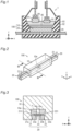
- FIG. 1 is a cross-sectional view of an exemplary electrolytic furnace for smelting aluminum, i.e., electrolytic furnace 1, schematically showing its entire construction.
- the electrolytic furnace 1 includes a cathode assembly 100 according to a first embodiment of the present invention.
- a plurality of cathode assemblies 100 are arranged in the depth direction (i.e., y-direction) in FIG. 1 .
- Each of the cathode assemblies 100 includes a cathode block 10 made of carbon and two collector bar units 20.
- the cathode blocks 10 constitute the furnace bottom of the electrolytic furnace 1.
- Each collector bar unit 20 includes metallic collector bars (details of their construction will be given further below) and is electrically connected to the cathode block 10 at these collector bars. For each collector bar unit 20, one end extends outside the electrolytic furnace 1.
- the electrolytic furnace 1 includes an anode 91, a shell 92, and a lining 93, among other components. Inside the electrolytic furnace 1 is contained melt 94 that contains aluminum oxide.
- the collector bar units 20 as well as the anode 91 are electrically connected to a power source, not shown.
- the power source applies a voltage between the cathode blocks 10 and the anode 91. This reduces the aluminum oxide in the melt 94 to aluminum 95.
- FIG. 2 is a schematic perspective view of the construction of the cathode assembly 100.
- FIG. 3 is a cross-sectional view taken along line III-III of FIG. 2 .
- the cathode assembly 100 includes a cathode block 10 and two collector bar units 20.
- the cathode block 10 is made of carbon.
- Cathode block made of carbon encompasses a cathode block made of a composite material of TiB 2 , TiC or the like with carbon.
- the cathode block 10 is preferably made of graphite.
- the cathode block 10 has the shape of a rectangular parallelepiped, and includes a groove 10a in its bottom surface. In addition to the bottom surface of the cathode block 10, the groove 10a is open in side surfaces of the cathode block 10 (i.e., surfaces perpendicular to the x-direction in FIG. 2 ). Two collector bar units 20 are inserted into the groove 10a.
- Each of the collector bar units 20 includes two collector bars (i.e., a collector bar 21 and a collector bar 22), and a plurality of spacing adjustment members 23 ( FIG. 3 ).
- Each of the collector bars 21 and 22 is made of a metal, preferably steel. Each of the collector bars 21 and 22 is shaped to extend in the same direction as the groove 10a (i.e., x-direction in FIG. 2 ). The collector bars 21 and 22 are located within the groove 10a and arranged in the width direction of the groove 10a. More specifically, the width direction of the groove 10a means the direction perpendicular to both the direction in which the groove 10a extends (i.e., x-direction in FIG. 2 ) and the vertical direction (i.e., z-direction in FIG. 2 ), i.e., the width direction of the groove 10a means the y-direction in FIG. 2 .
- the spacing adjustment members 23 ( FIG. 3 ) are disposed between the collector bars 21 and 22 to adjust the spacing s between the collector bars 21 and 22. Details of the construction of the spacing adjustment members 23 and the method of adjusting the spacing s will be given further below.
- the collector bars 21 and 22 include surfaces 211 and 221 ( FIG. 3 ) that contact the respective side surfaces of the groove 10a. It is preferable that the surfaces 211 and 221 fit snugly in the respective side surfaces of the groove 10a.
- FIG. 2 and 3 show an implementation where, as seen in a cross section perpendicular to the direction in which the groove 10a of the cathode block 10 extends (i.e., yz-cross section in FIG. 3 ), the groove 10a has a trapezoidal cross-sectional shape of an opening with a width decreasing toward the bottom surface. This cross-sectional shape is preferable because it is capable of preventing the collector bar unit 20 from dropping through the bottom surface. Nevertheless, the groove 10a may have any cross-sectional shape.
- the groove 10a may have a rectangular cross-sectional shape, for example.
- the collector bars 21 and 22, too, may have any cross-sectional shape. Nevertheless, as discussed above, it is preferable that the surfaces 211 and 221 that contact the respective side surfaces of the groove 10a fit snugly in the respective side surfaces of the groove 10.
- the gap between the collector bars 21 and 22 is preferably filled with a filler.
- the filler may be cement, for example.
- a spacer of a thermoplastic resin or a metal or alloy with a melting point not higher than 700 °C is positioned between the collector bars 21 and 22, for example.
- a spacer of a thermoplastic resin or a metal or alloy with a melting point not higher than 700 °C is positioned at least one of between the collector bars 21 and 22 (if the above-mentioned filler fills this space, at least one between the collector bar 21 and the filler and between the collector bar 22 and the filler), between the collector bar 21 and the associated side surface of the groove 10a, and between the collector bar 22 and the associated side surface of the groove 10a.
- the metal with a melting point not higher than 700 °C may be aluminum, for example. It is preferable that the spacer is sheet-shaped.
- FIG. 4 is an exploded schematic perspective view of the construction of the collector bar unit 20.
- the collector bar unit 20 includes collector bars 21 and 22 and a plurality of spacing adjustment members 23.
- the spacing adjustment members 23 are located between the collector bars 21 and 22 and arranged in the longitudinal direction of the collector bars 21 and 22, spaced apart from one another by generally the same distance.
- the spacing adjustment members 23 are disposed such that they will be present only inside the cathode block 10, and not outside the cathode block 10, when the collector bar unit 20 has been inserted into the groove 10a ( FIG. 2 ) of the cathode block 10.
- the spacing adjustment members 23 may have high or low electrical conductivity.
- the spacing adjustment members 23 may be made of metal, for example.
- Each of the spacing adjustment members 23 includes a threaded portion 23a at one end and a threaded portion 23b at the other.
- the collector bar 21 includes threaded holes 21a that allow the threaded portions 23a to be screwed therein.
- the collector bar 22 includes threaded holes 22a that allow the threaded portions 23b to be screwed therein.
- the spacing s ( FIG. 3 ) between the collector bars 21 and 22 may be adjusted by changing the amount of screwing between the threaded portions 23a and the threaded holes 21a and the amount of screwing between the threaded portions 23b and the threaded holes 22a.
- a threaded portion 23a and a threaded portion 23b have threads in opposite directions. Specifically, if a threaded portion 23a has a right-handed thread, a threaded portion 23b has a left-handed thread. If a threaded portion 23a has a left-handed thread, a threaded portion 23b has a right-handed thread. In this construction, rotating a spacing adjustment member 23 in one direction moves both the threaded portions 23a and 23b to be tightened simultaneously (or loosed simultaneously). Thus, the collector bars 21 and 22 can be moved in a uniform manner.
- each collector bar unit 20 includes collector bars 21 and 22 arranged in the width direction of the groove 10a.
- the collector bar unit 20 further includes spacing adjustment members 23 that adjust the spacing s ( FIG. 3 ) between the collector bars 21 and 22.
- rotating the spacing adjustment members 23 in a direction that increases the spacing s increases the contact pressure between the collector bars 21, 22 and the cathode block 10.
- rotating the spacing adjustment members 23 in a direction that reduces the spacing s reduces the contact pressure between the collector bars 21, 22 and the cathode block 10.
- the present embodiment enables adjustment of the contact pressure between the collector bars 21, 22 and the cathode block 10. This enables adjustment of the contact resistance between the collector bars 21, 22 and the cathode block 10.
- variations in processing may cause variations in the gaps between the collector bars and groove 10a. This may cause variations in contact resistance, particularly in a low-temperature range (e.g., the temperature range from room temperature up to approximately 500 °C).
- a low-temperature range e.g., the temperature range from room temperature up to approximately 500 °C.
- an electrolytic furnace 1 FIG. 1
- a plurality of cathode assemblies 100 may be used. Typically, the temperature in an electrolytic furnace 1 is raised by electrical resistance heating (i.e., resistor baking) from room temperature to near an operational temperature (e.g., approximately 960 °C).
- the gaps between the collector bars and groove 10a may be filled by pouring molten cast iron therein.
- Such methods involving casting cast iron require a large workload.
- the present embodiment will simplify the work of connecting the cathode block with the collector bars compared with methods involving casting cast iron. Further, it will reduce the energy costs associated with the heating for melting cast iron and the preheating of the cathode block and collector bars. Furthermore, since there is no risk of breaking due to a thermal shock, the manufacturing cost will be reduced.
- the present embodiment further produces the effect of reducing variations in the contact resistance between the cathode block 10 and the collector bars 21, 22 during temperature rise in the electrolytic furnace 1, as will be discussed below.
- the cathode blocks 10 and collector bars 21 and 22 thermally expand such that the contact pressures between the collector bars 21 and 22 and the cathode blocks 10 vary.
- a temperature gradient may be generated in the electrolytic furnace, which may cause non-uniform thermal expansion within the electrolytic furnace.
- FIG. 10 of U.S. Patent No. 7776190 shows that a foil of expanded graphite may be provided in a cathode slot (i.e., groove) to reduce contact resistance. Meanwhile, the same graph shows that, in the range of contact pressure up to 2N/mm 2 , an increase in contact pressure causes a rapid change in contact resistance from a value not lower than 100 m ⁇ cm 2 to a value near 25 m ⁇ cm 2 .
- Non-uniform thermal expansion may result in non-uniform contact pressure, which in turn may result in non-uniform contact resistance, causing non-uniform current.
- a large amount of non-uniform current may cause rapid local temperature increase, which may cause local oxidation or breaking of the affected cathode block 10.
- the spacing adjustment members 23 may be used to adjust contact pressure to a predetermined level (e.g., 2N/mm 2 ) or higher in advance when the assembly is still at room temperature. This enables preventing contact resistance from significantly varying due to thermal expansion during temperature rise.
- the spacing adjustment members 23 include a mechanism that adjusts the spacing s using threads, which enables fine adjustment of contact pressure. Furthermore, since a plurality of spacing adjustment members 23 are arranged in the longitudinal direction of the collector bars 21 and 22, contact pressure can be adjusted across the entire length of the collector bars 21 and 22.
- the cathode assembly 100 is heated to a high temperature (e.g., 960 °C). Thermal expansion of the collector bars 21 and 22 may cause deformation of the spacing adjustment members 23. Filling the gap between the collector bars 21 and 22 with a filler to increase strength enables maintaining contact pressure when the assembly is at high temperature.
- a high temperature e.g., 960 °C
- a spacer of a thermoplastic resin or a metal or alloy with a melting point not higher than 700 °C is provided between the collector bars 21 and 22, for example. Providing a spacer of a thermoplastic resin or a metal or alloy with a melting point not higher than 700 °C will mitigate stress caused by thermal expansion of the collector bars 21 and 22, thereby preventing the cathode block 10 from breaking.
- FIG. 4 shows an implementation where the collector bar unit 20 includes six spacing adjustment members 23, any number of spacing adjustment members 23 may be provided. Only one spacing adjustment member 23 may be provided. Nevertheless, providing a plurality of spacing adjustment members 23 arranged in the longitudinal direction of the collector bars 21 and 22 is preferable because this enables adjusting the contact pressure between the collector bars 21, 22 and the cathode block 10 across the length of the collector bars. If a plurality of spacing adjustment members 23 are to be provided, the spacing between the spacing adjustment members 23 need not be equal. Further, in addition to inside of the cathode block 10, spacing adjustment members 23 may also be provided that are disposed such that they will be present outside of the cathode block 10.
- a plurality of spacing adjustment members 23 are to be provided arranged in the longitudinal direction of the collector bars 21 and 22, adjustment may be made such that the contact pressure between the collector bars 21 and 22 and the cathode block 10 varies depending on the position along the longitudinal direction of the collector bars 21 and 22.
- adjustment may be made such that the contact pressure between the collector bars 21, 22 and the cathode block 10 at the middle of the cathode block 10 as determined along the longitudinal direction of the collector bars 21 and 22 is higher than at the ends of the cathode block 10.
- the contact resistance of the cathode block 10 at the ends thereof is higher than that at the middle of the cathode block 10.
- the cathode assembly 100 according to the first embodiment of the present invention has been described.
- the present embodiment will simplify the work of connecting the cathode block with the collector bars.
- the cathode assembly 100 includes two collector bar units 20.
- two collector bar units 20 are connected to one cathode block 10.
- only one collector bar unit 20 may be connected to the cathode block 10, or three or more units may be connected.
- the above embodiment describes an implementation where the collector bar units 20 are inserted through two opposite sides of the cathode block 10, a collector bar unit 20 may be passed from one side to the opposite side of the cathode block 10.
- each collector bar unit 20 ( FIG. 4 ) is replaced by a collector bar unit 30 ( FIG. 5 ) or a collector bar unit 50 ( FIG. 6 ), respectively.
- FIG. 5 is an exploded schematic perspective view of the construction of a collector bar unit 30 included in a cathode assembly according to a second embodiment of the present invention.
- the collector bar unit 30 includes a collector bar 31 and a collector bar 32, and a plurality of spacing adjustment members 33.
- Each spacing adjustment member 33 includes a threaded portion 33a.
- the collector bar 31 includes threaded holes 31a that allow such threaded portions 33a to be screwed therein.
- the collector bar 32 includes threaded holes 32a that allow such threaded portions 33a to be screwed therein. Otherwise, the construction of the collector bars 31 and 32 is the same as that of the collector bars 21 and 22 ( FIG. 4 ).
- a spacing adjustment member 23 of the collector bar unit 20 includes threaded portions at both ends thereof
- a spacing adjustment member 33 includes a threaded portion 33a at one end only.
- the spacing between the collector bars 31 and 32 is adjusted by screwing the threaded portion 33a of each spacing adjustment member into a threaded hole of one of the collector bars 31 and 32 (i.e., threaded hole 31a or 32a) and bringing the end of the member that includes no threaded portion 33a into abutment with the other collector bar.
- the present embodiment enables adjusting the contact resistance between the collector bars and the cathode block. This will simplify the work of connecting the cathode block with the collector bars.
- FIG. 5 shows an implementation where the threaded holes 31a and threaded holes 32a are alternately arranged along the longitudinal direction of the collector bars 31 and 32
- the threaded holes 31a and threaded holes 32a may be arranged in any manner.
- no thread holes 31a, and only threaded holes 32a may be provided.
- FIG. 6 is an exploded schematic perspective view of the construction of a collector bar unit 50 included in a cathode assembly according to a third embodiment of the present invention. Unlike FIG. 4 and 5 , FIG. 6 shows the collector bar unit 50 as seen looking at the bottom of the cathode block.
- the collector bar unit 50 includes a collector bar 51 and a collector bar 52, and a plurality of spacing adjustment members 53.
- the collector bars 51 and 52 include semi-columnar grooves 51a and 52a that will form columnar recesses when the collector bars 51 and 52 are positioned side-by-side.
- Each spacing adjustment member 53 is positioned in a recess formed by grooves 51a and 52a. Otherwise, the construction of the collector bars 51 and 52 is the same as that of the collector bars 21 and 22 ( FIG. 4 ).
- FIG. 7 is a schematic cross-sectional view of the construction of a spacing adjustment member 53.
- the spacing adjustment member 53 includes a bolt 531, a sleeve 532, and a base 533.
- the base 533 includes a threaded hole 533a that allows the bolt 531 to be screwed therein.
- the base 533 is tapered in shape where the outer diameter increases as it goes away from the end surface in which the threaded hole 533a is open.
- the sleeve 532 is cylindrical in shape and is positioned between the head of the bolt 531 and the base 533 to surround the shaft of the bolt 531.
- the sleeve 532 includes a slit 532a ( FIG. 6 ) that is open in its end portion adjacent to the base 533.
- the sleeve 532 When the bolt 531 is screwed into the threaded hole 533a in the base 533, the sleeve 532 is pushed by the head of the bolt 531 and moves toward the base 533. At this time, since the base 533 is tapered in shape, the sleeve 532 receives stress in directions that expand it outwardly. This stress enlarges the slit 532a such that the lower end portion of the sleeve 532 expands outwardly.
- each spacing adjustment member 53 is positioned in a recess formed by grooves 51a and 52a.
- the sleeve 532 expands outwardly, it pushes the collector bars 51 and 52 to increase the spacing therebetween.
- the spacing between collector bars 51 and 52 can be increased by screwing in the bolts 531. At this time, the spacing between the collector bars 51 and 52 can be adjusted by changing the amount of screw-in of the bolts 531.
- the present embodiment enables adjusting the contact resistance between the collector bars and the cathode block. This will simplify the work of connecting the cathode block with the collector bars.
- the spacing adjustment members 53 are only required to be constructed such that their outer diameter increases in response to some operation.
- a spacing adjustment member may be constructed such that its outer diameter is increased by tightening a nut.
- the spacing adjustment members are only required to be able to adjust the spacing between two collector bars by means of a thread mechanism, and may have various specific constructions.
- a spacing adjustment member includes a mechanism that adjusts the spacing between two collector bars using threads.
- the thread mechanism enables even finer adjustment of the contact pressure between the two collector bars and the cathode block.
- a cathode assembly according to a fourth embodiment of the present invention is only different from the cathode assembly 100 ( FIG. 2 ) in the construction of the collector bar units.
- each collector bar unit of the cathode assembly according to the present embodiment further includes a conductive member / conductive members made of a metal with a higher electrical conductivity than that for the collector bars 21 and 22.
- the conductive member(s) may be made of copper, for example.
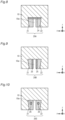
- FIG. 8 to 10 show exemplary arrangements of a conductive member / conductive members.
- the collector bar unit 20A in addition to the components included in the collector bar unit 20 ( FIG. 3 ), the collector bar unit 20A further includes a conductive member 24.
- FIG. 8 does not show the spacing adjustment members 23. The same applies to FIG. 9 and 10 .
- the conductive member 24 is positioned between the upper surfaces of the collector bars 21 and 22 and the bottom surface of the groove 10a. The conductive member 24 may be present across the entire extension of the groove 10a, or may be present intermittently.
- the collector bar unit 20B further includes conductive members 25.
- the conductive members 25 are positioned on those surfaces of the respective collector bars 21 and 22 which are opposite to each other.
- the collector bar unit 20C in addition to the components included in the collector bar unit 20 ( FIG. 3 ), the collector bar unit 20C further includes conductive members 26.
- the conductive members 26 are embedded within the collector bars 21 and 22.
- the collector bar unit further includes a conductive member / conductive members made of a metal with a higher electrical conductivity than that for the collector bars 21 and 22, cathode voltage drop (CVD) will be reduced.
- CVD cathode voltage drop
- the conductive member(s) shown in FIG. 8 to 10 are merely illustrative, and the conductive members are not limited to these arrangements. Further, although the above embodiment describes constructions starting from the collector bar unit 20 described in connection with the first embodiment where the collector bar unit 20 further includes conductive members, the collector bar units described in connection with the second and third embodiments may be combined with such conductive members.
- a cathode assembly according to a fifth embodiment of the present invention is different from the cathode assemblies according to the first to fourth embodiments in the shape of the collector bars included in the collector bar units.
- each of the collector bars of the cathode assembly according to the present embodiment includes projections on a surface.
- FIG. 11 is a schematic perspective view of the construction of a collector bar 21A, which is an exemplary collector bar included in the cathode assembly according to the present embodiment.
- the upper surface of the collector bar 21A is provided with a plurality of dot-shaped projections 21Aa.
- the projections 21Aa may be created by machining the collector bar, or may be created by welding separate metallic components to the collector bar. Although not limiting, it is preferable that the projections 21Aa are disposed such that they will only be present inside the cathode block when the collector bar unit has been inserted into the groove of the cathode block.
- the collector bar 21A receives the load of the cathode block 10 ( FIG. 1 ) and the loads of the melt 94 and aluminum 95 applied thereto.
- Providing the projections 21Aa reduces the contact area between the collector bar 21A and the cathode block 10. This increases the contact pressure, thereby reducing the contact resistance between the collector bar 21A and cathode block 10.
- a conductive member 24 is positioned between the upper surface of collector bars 21A and the bottom surface of the groove 10a ( FIG. 9 )
- providing the projections reduces the contact resistance between the collector bars 21A and conductive member 24.
- FIG. 12 is a schematic perspective view of the construction of a collector bar 21B, which is another exemplary collector bar included in the cathode assembly according to the present embodiment.
- the upper surface of the collector bar 21B is provided with a plurality of line-shaped of projections 21Ba.
- the construction of the collector bar 21B also reduces the contact resistance between the collector bar 21B and cathode block 10 ( FIG. 1 ) or the contact resistance between the collector bar 21B and conductive member 24 ( FIG. 8 ).
- the shapes and arrangements of the projections 21Aa and projections 21Ba shown in FIG. 11 and 12 are merely illustrative, and the projections are not limited to these shapes and arrangements.
- FIG. 13 is a schematic cross-sectional view of the construction of a cathode assembly 101 according to a sixth embodiment of the present invention.
- the cathode assembly 101 is different from the cathode assembly 100 ( FIG. 3 ) in the size of the cathode block.
- the cathode assembly 101 includes a cathode block 11 that replaces the cathode block 10 ( FIG. 3 ) of the cathode assembly 100.
- the cathode assembly 101 may be suitably used to replace a cathode assembly including a cathode block known as a double-slot-type cathode block.
- FIG. 14 is a schematic cross-sectional view of the construction of a cathode assembly 900, which is an exemplary cathode assembly including a double-slot-type cathode block.
- the cathode assembly 900 includes a cathode block 910 and two collector bars 920.
- the cathode block 910 includes two grooves 910a, where each of the grooves 910a receives a collector bar 920 inserted therein.
- the cathode block 11 of the cathode assembly 101 ( FIG. 13 ) includes a single wide groove 11a that replaces the two grooves 910a of the cathode block 910 ( FIG. 14 ).
- the collector bar unit 20 is inserted into this groove 11a.
- the collector bar unit 20 a clearance is formed between the collector bar 21 and the collector bar 22.
- the total cross-sectional area of the collector bars is smaller, although slightly, than that for implementations with a single collector bar.
- the cross-sectional area of the groove of the cathode block is increased, as shown in FIG. 13 and 14 ; thus, even if a clearance is provided between the collector bars 21 and 22, the total cross-sectional area of the collector bars does not decrease. It is even possible to increase the total cross-sectional area of the collector bars over that before replacement. This will reduce CVD.
- FIG. 15 is a schematic cross-sectional view of the construction of a cathode assembly 102 according to a seventh embodiment of the present invention.
- the cathode assembly 102 includes a filler 61 located between the collector bars 21 and 22 and two spacers 62 located between the two collector bars 21 and 22 and the filler 61.
- the filler 61 may or may not be conductive.
- the filler 61 may be, for example, cement such as aluminum cement, ramming paste, ceramics, steel shot, or coke particles.
- the spacers 62 are made of a thermoplastic resin or a metal or alloy with a melting point not higher than 700 °C.
- the metal with a melting point not higher than 700 °C may be aluminum, for example.
- the spacers are sheet-shaped.
- the spacers 62 may or may not be conductive.
- the spacers 62 are preferably made of a thermoplastic resin.
- spacers 62 are positioned between the collector bars 21 and 22 and the filler 61; alternatively, a spacer may only be provided between one of the collector bars 21 and 22 and the filler 61. In other words, it is sufficient if a spacer 62 is provided between at least one of the collector bars 21 and 22 and the filler 61.
- the cathode assembly 102 is heated to a high temperature (e.g., 960 °C). Thermal expansion of the collector bars 21 and 22 may deform the spacing adjustment members 23. According to the present embodiment, the filler 61 fills the gap between the collector bars 21 and 22 to increase strength, thereby maintaining the contact pressure when the assembly is at high temperature.
- a high temperature e.g., 960 °C.
- spacers 62 mitigates stress due to thermal expansion of the collector bars 21 and 22, thus preventing the cathode block 10 from breaking. Further, when the spacers 62 soften, this reduces changes in contact pressure during temperature rise will be reduced.
- FIG. 16 is a schematic cross-sectional view of the construction of the test instrument 70 used for this measurement.
- FIG. 17 shows a photograph of the test instrument 70.
- the components 71 and 72 in FIG. 16 were circular columns made of steel corresponding to the collector bars 21 and 22 in FIG. 15 .
- the component 73 was a component corresponding to the spacing adjustment member 23 and, similar to the spacing adjustment member 23, included threaded portions at both ends.
- the component 74 was made of alumina cement corresponding to the filler 61, while the components 75 were sheets of a thermoplastic resin corresponding to the spacers 62.
- the components 71 and 72 were fixed in such a manner that the distance D between the upper end 71a of the component 71 and the lower end 72a of the component 72 was kept constant.
- the component 73 was operated to apply an initial load of about 20 kN to the components 71 and 72 and, with this state kept, the gap between the two components 75 was filled with alumina cement to form the component 74.
- the components 71 and 72 were heated by heating equipment, not shown, and the changes in load caused by thermal expansion of the components 71 and 72, among other components, were measured.
- FIG. 18 is a graph showing the relationship between temperature and load obtained by this test.
- the load increased from the initial value of 20 kN to about 30 kN in the temperature range from room temperature to about 100 °C before staying near 30 kN in the temperature range up to about 400 °C.
- the load decreased temporarily in the temperature range near 100 °C presumably because the components 75 of thermoplastic resin softened in this range.
- the load decreased temporarily in the temperature range near 250 °C presumably because the steel components 71 and 72 softened in this range.
- the load was stable near 30 kN in the temperature range from about 100 °C to about 400 °C, with little variation.
- contact pressure is adjusted to a predetermined level (e.g., 2 N/mm 2 ) or higher in advance when the assembly is at room temperature to prevent contact resistance from significantly varying due to thermal expansion during temperature rise.
- a predetermined level e.g. 2 N/mm 2
- variations in contact pressure will be reduced in the temperature range from room temperature to 500 °C, in which otherwise variations could easily occur in the temperature distribution in the furnace.
Landscapes
- Chemical & Material Sciences (AREA)
- Engineering & Computer Science (AREA)
- Chemical Kinetics & Catalysis (AREA)
- Electrochemistry (AREA)
- Materials Engineering (AREA)
- Metallurgy (AREA)
- Organic Chemistry (AREA)
- Electrolytic Production Of Metals (AREA)
- Vertical, Hearth, Or Arc Furnaces (AREA)
Abstract
Description
- The present invention relates to a cathode assembly.
- An electrolytic furnace for aluminum smelting has a negative electrode (i.e., cathode) constituted by cathode blocks made of carbon. The cathode blocks are installed in a steel box called a "shell" and contains the furnace bottom of the electrolytic furnace. Another role played by the cathode blocks is to supply the electrolytic bath with electrons.
- A cathode block is supplied with electrons via a metallic collector bar. An assembly with a cathode block and a collector bar connected thereto will be hereinafter referred to as "cathode assembly".
- Connection between a cathode block and a collector bar is established by casting cast iron in between the two components. Specifically, it is achieved by forming a groove in the bottom surface of the cathode block and fitting the collector bar therein, and pouring molten cast iron heated to about 1250 °C into the gap.
-
WO 2018/134754 A1 discloses a cathode assembly including a cathode body made of a carbonaceous material and at least one cathode collector bar made of a metallic material. This cathode collector bar includes two bar elements. Each of the two bar elements has a main side surface to contact a side of a slot in the cathode body and a tapered surface. The two tapered surfaces form the contact line between the two bar elements. -
JP 2017-534770 A -
U.S. Patent No. 7776190 discloses a cathode used in an aluminum electrolysis cell. This cathode includes: a cathode block selected from: a carbon cathode block and a graphite cathode block, the cathode block having a collector bar slot formed therein; a collector bar made of steel and positioned in the collector bar slot; and an expanded graphite that lines the collector bar slot.FIG. 10 of this publication shows that contact resistance can be reduced by providing a foil of expanded graphite in the cathode slot (i.e., groove). -
- Patent Document 1:
WO 2018/134754 A1 - Patent Document 2:
JP 2017-534770 A - Patent Document 3:
U.S. Patent No. 7776190 - Such methods involving casting cast iron require a large workload and, in addition, energy costs associated with the heating for melting cast iron and the preheating of the cathode block and collector bars. Further, if the preheating temperature is too high, the cathode block oxidizes; in view of this, the preheating temperature can only be raised to 400 to 500 °C, which poses a risk of the cathode block breaking due to a thermal shock during the pouring of molten cast iron.
- The start-up of an electrolytic furnace is typically performed by raising the furnace temperature using resistive heat, a method known as resistor baking. In resistor baking, a DC current is passed through the electrolytic furnace to produce resistive heat, which is used to raise the temperature in the furnace. During start-up, for example, if the contact pressures between some cathode blocks and their collector bars are different from the others, electric current concentrates in those cathode assemblies which are experiencing high contact pressure, causing an abnormal temperature increase in these cathode assemblies. The cathode assemblies with abnormal temperature rise experience larger thermal expansion of the collector bars, making the contact between the cathode blocks and collector bars even stronger. This means an even lower contact resistance in those cathode assemblies, causing further concentration of current. There is a risk that a thermal shock by this mechanism may cause a cathode block to break.
- An object of the present invention is to provide a cathode assembly that enables simplifying the work of connecting a cathode block with a collector bar. Another object of the present invention is to provide a cathode assembly that enables reducing variations in the contact resistance during temperature increase in the electrolytic furnace.
- A cathode assembly according to one embodiment of the present invention is a cathode assembly used in an electrolytic furnace for aluminum smelting, including: a cathode block made of carbon and having a groove; and a collector bar unit inserted into the groove, the collector bar unit including: two collector bars made of a metal and shaped to extend in the same direction as the groove and arranged in a width direction of the groove; and a spacing adjustment member configured to adjust a spacing between the two collector bars, the spacing adjustment member including a mechanism adapted to adjust the spacing between the two collector bars using a thread.
- The present invention simplifies the work of connecting a cathode block with a collector bar. The present invention also reduces variations in the contact resistance between the cathode block and collector bar during temperature increase in the electrolytic furnace.
-
- [
FIG. 1] FIG. 1 is a cross-sectional view of an exemplary electrolytic furnace for aluminum smelting, schematically showing its entire construction. - [
FIG. 2] FIG. 2 is a schematic perspective view of the construction of a cathode assembly according to a first embodiment of the present invention. - [
FIG. 3] FIG. 3 is a cross-sectional view taken along line III-III ofFIG. 2 . - [
FIG. 4] FIG. 4 is an exploded schematic perspective view of the construction of the collector bar unit included in the cathode assembly ofFIG. 2 . - [
FIG. 5] FIG. 5 is an exploded schematic perspective view of the construction of a collector bar unit included in a cathode assembly according to a second embodiment of the present invention. - [
FIG. 6] FIG. 6 is an exploded schematic perspective view of the construction of a collector bar unit included in a cathode assembly according to a third embodiment of the present invention. - [
FIG. 7] FIG. 7 is a schematic cross-sectional view of the construction of a spacing adjustment member included in the collector bar unit ofFIG. 6 . - [
FIG. 8] FIG. 8 is a schematic cross-sectional view of an exemplary arrangement of a conductive member. - [
FIG. 9] FIG. 9 is a schematic cross-sectional view of an exemplary arrangement of conductive members. - [
FIG. 10] FIG. 10 is a schematic cross-sectional view of an exemplary arrangement of conductive members. - [
FIG. 11] FIG. 11 is a schematic perspective view of the construction of an exemplary collector bar. - [
FIG. 12] FIG. 12 is a schematic perspective view of the construction of another exemplary collector bar. - [
FIG. 13] FIG. 13 is a schematic cross-sectional view of the construction of a cathode assembly according to a sixth embodiment of the present invention. - [
FIG. 14] FIG. 14 is a schematic cross-sectional view of the construction of an exemplary cathode assembly including a double-slot-type cathode block. - [
FIG. 15] FIG. 15 is a schematic cross-sectional view of the construction of a cathode assembly according to a seventh embodiment of the present invention. - [
FIG. 16] FIG. 16 is a schematic cross-sectional view of the construction of a test instrument used to measure changes in contact pressure caused by thermal expansion. - [
FIG. 17] FIG. 17 is a photograph of the test instrument. - [
FIG. 18] FIG. 18 is a graph showing the relationship between temperature and load. - Now, embodiments of the present invention will be described in detail with reference to the drawings. In the drawings, the same or corresponding elements are labeled with the same reference numerals, and their description will not be repeated. The size ratios of the components shown in the drawings do not necessarily indicate the actual size ratios.
-
FIG. 1 is a cross-sectional view of an exemplary electrolytic furnace for smelting aluminum, i.e.,electrolytic furnace 1, schematically showing its entire construction. - The
electrolytic furnace 1 includes acathode assembly 100 according to a first embodiment of the present invention. A plurality ofcathode assemblies 100 are arranged in the depth direction (i.e., y-direction) inFIG. 1 . Each of thecathode assemblies 100 includes acathode block 10 made of carbon and twocollector bar units 20. The cathode blocks 10 constitute the furnace bottom of theelectrolytic furnace 1. Eachcollector bar unit 20 includes metallic collector bars (details of their construction will be given further below) and is electrically connected to thecathode block 10 at these collector bars. For eachcollector bar unit 20, one end extends outside theelectrolytic furnace 1. - In addition to the
cathode assemblies 100, theelectrolytic furnace 1 includes ananode 91, ashell 92, and alining 93, among other components. Inside theelectrolytic furnace 1 is containedmelt 94 that contains aluminum oxide. Thecollector bar units 20 as well as theanode 91 are electrically connected to a power source, not shown. The power source applies a voltage between the cathode blocks 10 and theanode 91. This reduces the aluminum oxide in themelt 94 toaluminum 95. - The construction of a
cathode assembly 100 will be described in detail with reference toFIG. 2 and 3. FIG. 2 is a schematic perspective view of the construction of thecathode assembly 100.FIG. 3 is a cross-sectional view taken along line III-III ofFIG. 2 . - As discussed above, the
cathode assembly 100 includes acathode block 10 and twocollector bar units 20. - The
cathode block 10 is made of carbon. "Cathode block made of carbon" encompasses a cathode block made of a composite material of TiB2, TiC or the like with carbon. Thecathode block 10 is preferably made of graphite. Thecathode block 10 has the shape of a rectangular parallelepiped, and includes agroove 10a in its bottom surface. In addition to the bottom surface of thecathode block 10, thegroove 10a is open in side surfaces of the cathode block 10 (i.e., surfaces perpendicular to the x-direction inFIG. 2 ). Twocollector bar units 20 are inserted into thegroove 10a. - Each of the
collector bar units 20 includes two collector bars (i.e., acollector bar 21 and a collector bar 22), and a plurality of spacing adjustment members 23 (FIG. 3 ). - Each of the collector bars 21 and 22 is made of a metal, preferably steel. Each of the collector bars 21 and 22 is shaped to extend in the same direction as the
groove 10a (i.e., x-direction inFIG. 2 ). The collector bars 21 and 22 are located within thegroove 10a and arranged in the width direction of thegroove 10a. More specifically, the width direction of thegroove 10a means the direction perpendicular to both the direction in which thegroove 10a extends (i.e., x-direction inFIG. 2 ) and the vertical direction (i.e., z-direction inFIG. 2 ), i.e., the width direction of thegroove 10a means the y-direction inFIG. 2 . - The spacing adjustment members 23 (
FIG. 3 ) are disposed between the collector bars 21 and 22 to adjust the spacing s between the collector bars 21 and 22. Details of the construction of thespacing adjustment members 23 and the method of adjusting the spacing s will be given further below. - The collector bars 21 and 22 include
surfaces 211 and 221 (FIG. 3 ) that contact the respective side surfaces of thegroove 10a. It is preferable that thesurfaces groove 10a. -
FIG. 2 and 3 show an implementation where, as seen in a cross section perpendicular to the direction in which thegroove 10a of thecathode block 10 extends (i.e., yz-cross section inFIG. 3 ), thegroove 10a has a trapezoidal cross-sectional shape of an opening with a width decreasing toward the bottom surface. This cross-sectional shape is preferable because it is capable of preventing thecollector bar unit 20 from dropping through the bottom surface. Nevertheless, thegroove 10a may have any cross-sectional shape. Thegroove 10a may have a rectangular cross-sectional shape, for example. - The collector bars 21 and 22, too, may have any cross-sectional shape. Nevertheless, as discussed above, it is preferable that the
surfaces groove 10a fit snugly in the respective side surfaces of thegroove 10. - Although not shown, the gap between the collector bars 21 and 22 is preferably filled with a filler. The filler may be cement, for example.
- Although not shown, it is preferable that a spacer of a thermoplastic resin or a metal or alloy with a melting point not higher than 700 °C is positioned between the collector bars 21 and 22, for example. Specifically, it is preferable that a spacer of a thermoplastic resin or a metal or alloy with a melting point not higher than 700 °C is positioned at least one of between the collector bars 21 and 22 (if the above-mentioned filler fills this space, at least one between the
collector bar 21 and the filler and between thecollector bar 22 and the filler), between thecollector bar 21 and the associated side surface of thegroove 10a, and between thecollector bar 22 and the associated side surface of thegroove 10a. The metal with a melting point not higher than 700 °C may be aluminum, for example. It is preferable that the spacer is sheet-shaped. - Next, details of the construction of the
spacing adjustment members 23 and the method of adjusting the spacing s (FIG. 3 ) between the collector bars 21 and 22 will be described with reference toFIG. 4. FIG. 4 is an exploded schematic perspective view of the construction of thecollector bar unit 20. As discussed above, thecollector bar unit 20 includes collector bars 21 and 22 and a plurality ofspacing adjustment members 23. - The
spacing adjustment members 23 are located between the collector bars 21 and 22 and arranged in the longitudinal direction of the collector bars 21 and 22, spaced apart from one another by generally the same distance. Thespacing adjustment members 23 are disposed such that they will be present only inside thecathode block 10, and not outside thecathode block 10, when thecollector bar unit 20 has been inserted into thegroove 10a (FIG. 2 ) of thecathode block 10. - The
spacing adjustment members 23 may have high or low electrical conductivity. Thespacing adjustment members 23 may be made of metal, for example. - Each of the
spacing adjustment members 23 includes a threadedportion 23a at one end and a threadedportion 23b at the other. Thecollector bar 21 includes threadedholes 21a that allow the threadedportions 23a to be screwed therein. Thecollector bar 22 includes threadedholes 22a that allow the threadedportions 23b to be screwed therein. In this construction, the spacing s (FIG. 3 ) between the collector bars 21 and 22 may be adjusted by changing the amount of screwing between the threadedportions 23a and the threadedholes 21a and the amount of screwing between the threadedportions 23b and the threadedholes 22a. - According to the present embodiment, a threaded
portion 23a and a threadedportion 23b have threads in opposite directions. Specifically, if a threadedportion 23a has a right-handed thread, a threadedportion 23b has a left-handed thread. If a threadedportion 23a has a left-handed thread, a threadedportion 23b has a right-handed thread. In this construction, rotating aspacing adjustment member 23 in one direction moves both the threadedportions - In the construction of the
cathode assembly 100 according to the present embodiment, eachcollector bar unit 20 includes collector bars 21 and 22 arranged in the width direction of thegroove 10a. Thecollector bar unit 20 further includesspacing adjustment members 23 that adjust the spacing s (FIG. 3 ) between the collector bars 21 and 22. - With the
surfaces grooves 10a, rotating thespacing adjustment members 23 in a direction that increases the spacing s increases the contact pressure between the collector bars 21, 22 and thecathode block 10. On the contrary, rotating thespacing adjustment members 23 in a direction that reduces the spacing s reduces the contact pressure between the collector bars 21, 22 and thecathode block 10. - In other words, the present embodiment enables adjustment of the contact pressure between the collector bars 21, 22 and the
cathode block 10. This enables adjustment of the contact resistance between the collector bars 21, 22 and thecathode block 10. - In an arrangement where collector bars are simply placed in a
groove 10a, variations in processing may cause variations in the gaps between the collector bars andgroove 10a. This may cause variations in contact resistance, particularly in a low-temperature range (e.g., the temperature range from room temperature up to approximately 500 °C). In an electrolytic furnace 1 (FIG. 1 ), a plurality ofcathode assemblies 100 may be used. Typically, the temperature in anelectrolytic furnace 1 is raised by electrical resistance heating (i.e., resistor baking) from room temperature to near an operational temperature (e.g., approximately 960 °C). If there are variations in contact resistance among a plurality ofcathode assemblies 100, during temperature rise, electric current concentrates incathode assemblies 100 with low contact resistance, which may cause a local temperature increase. During operation, too, electric current concentrating incathode assemblies 100 with low contact resistance may cause local wear of the cathode electrolysis surfaces, or lead to biased thermal balance that may destabilize operations. - Conventionally, the gaps between the collector bars and
groove 10a may be filled by pouring molten cast iron therein. Such methods involving casting cast iron require a large workload. The present embodiment will simplify the work of connecting the cathode block with the collector bars compared with methods involving casting cast iron. Further, it will reduce the energy costs associated with the heating for melting cast iron and the preheating of the cathode block and collector bars. Furthermore, since there is no risk of breaking due to a thermal shock, the manufacturing cost will be reduced. - The present embodiment further produces the effect of reducing variations in the contact resistance between the
cathode block 10 and the collector bars 21, 22 during temperature rise in theelectrolytic furnace 1, as will be discussed below. - During temperature rise in the
electrolytic furnace 1, the cathode blocks 10 and collector bars 21 and 22 thermally expand such that the contact pressures between the collector bars 21 and 22 and the cathode blocks 10 vary. During temperature rise, a temperature gradient may be generated in the electrolytic furnace, which may cause non-uniform thermal expansion within the electrolytic furnace. -
FIG. 10 ofU.S. Patent No. 7776190 shows that a foil of expanded graphite may be provided in a cathode slot (i.e., groove) to reduce contact resistance. Meanwhile, the same graph shows that, in the range of contact pressure up to 2N/mm2, an increase in contact pressure causes a rapid change in contact resistance from a value not lower than 100 mΩ·cm2 to a value near 25 mΩ·cm2. - Non-uniform thermal expansion may result in non-uniform contact pressure, which in turn may result in non-uniform contact resistance, causing non-uniform current. A large amount of non-uniform current may cause rapid local temperature increase, which may cause local oxidation or breaking of the affected
cathode block 10. - According to the present embodiment, the
spacing adjustment members 23 may be used to adjust contact pressure to a predetermined level (e.g., 2N/mm2) or higher in advance when the assembly is still at room temperature. This enables preventing contact resistance from significantly varying due to thermal expansion during temperature rise. Particularly, according to the present embodiment, thespacing adjustment members 23 include a mechanism that adjusts the spacing s using threads, which enables fine adjustment of contact pressure. Furthermore, since a plurality ofspacing adjustment members 23 are arranged in the longitudinal direction of the collector bars 21 and 22, contact pressure can be adjusted across the entire length of the collector bars 21 and 22. - After contact pressure has been adjusted using the
spacing adjustment members 23, it is preferable to fill the gap between the collector bars 21 and 22 with a filler. During operation, thecathode assembly 100 is heated to a high temperature (e.g., 960 °C). Thermal expansion of the collector bars 21 and 22 may cause deformation of thespacing adjustment members 23. Filling the gap between the collector bars 21 and 22 with a filler to increase strength enables maintaining contact pressure when the assembly is at high temperature. - Further, it is preferable that a spacer of a thermoplastic resin or a metal or alloy with a melting point not higher than 700 °C is provided between the collector bars 21 and 22, for example. Providing a spacer of a thermoplastic resin or a metal or alloy with a melting point not higher than 700 °C will mitigate stress caused by thermal expansion of the collector bars 21 and 22, thereby preventing the
cathode block 10 from breaking. - Although
FIG. 4 shows an implementation where thecollector bar unit 20 includes sixspacing adjustment members 23, any number ofspacing adjustment members 23 may be provided. Only onespacing adjustment member 23 may be provided. Nevertheless, providing a plurality ofspacing adjustment members 23 arranged in the longitudinal direction of the collector bars 21 and 22 is preferable because this enables adjusting the contact pressure between the collector bars 21, 22 and thecathode block 10 across the length of the collector bars. If a plurality ofspacing adjustment members 23 are to be provided, the spacing between thespacing adjustment members 23 need not be equal. Further, in addition to inside of thecathode block 10,spacing adjustment members 23 may also be provided that are disposed such that they will be present outside of thecathode block 10. - If a plurality of
spacing adjustment members 23 are to be provided arranged in the longitudinal direction of the collector bars 21 and 22, adjustment may be made such that the contact pressure between the collector bars 21 and 22 and thecathode block 10 varies depending on the position along the longitudinal direction of the collector bars 21 and 22. - For example, adjustment may be made such that the contact pressure between the collector bars 21, 22 and the
cathode block 10 at the middle of thecathode block 10 as determined along the longitudinal direction of the collector bars 21 and 22 is higher than at the ends of thecathode block 10. In such implementations, as determined along the longitudinal direction of the collector bars 21 and 22, the contact resistance of thecathode block 10 at the ends thereof is higher than that at the middle of thecathode block 10. - In a typical cathode assembly, electric current tends to concentrate near the ends of the cathode block. A higher contact resistance at the ends of the
cathode block 10 as determined along the longitudinal direction of the collector bars 21 and 22, as discussed above, enables achieving a uniform distribution of current flowing through thecathode block 10. This will reduce decrease of overall efficiency and/or local wear. - The
cathode assembly 100 according to the first embodiment of the present invention has been described. The present embodiment will simplify the work of connecting the cathode block with the collector bars. - The above embodiment describes an implementation where the
cathode assembly 100 includes twocollector bar units 20. In other words, it describes an implementation where twocollector bar units 20 are connected to onecathode block 10. Alternatively, only onecollector bar unit 20 may be connected to thecathode block 10, or three or more units may be connected. Further, although the above embodiment describes an implementation where thecollector bar units 20 are inserted through two opposite sides of thecathode block 10, acollector bar unit 20 may be passed from one side to the opposite side of thecathode block 10. - Cathode assemblies according to second and third embodiments described below are only different from the cathode assembly 100 (
FIG. 2 ) in the construction of the collector bar units. Specifically, in the cathode assembly according to the second or third embodiment, each collector bar unit 20 (FIG. 4 ) is replaced by a collector bar unit 30 (FIG. 5 ) or a collector bar unit 50 (FIG. 6 ), respectively. -
FIG. 5 is an exploded schematic perspective view of the construction of acollector bar unit 30 included in a cathode assembly according to a second embodiment of the present invention. Thecollector bar unit 30 includes acollector bar 31 and acollector bar 32, and a plurality ofspacing adjustment members 33. - Each
spacing adjustment member 33 includes a threadedportion 33a. Thecollector bar 31 includes threadedholes 31a that allow such threadedportions 33a to be screwed therein. Similarly, thecollector bar 32 includes threadedholes 32a that allow such threadedportions 33a to be screwed therein. Otherwise, the construction of the collector bars 31 and 32 is the same as that of the collector bars 21 and 22 (FIG. 4 ). - While a
spacing adjustment member 23 of the collector bar unit 20 (FIG. 4 ) includes threaded portions at both ends thereof, aspacing adjustment member 33 includes a threadedportion 33a at one end only. According to the present embodiment, the spacing between the collector bars 31 and 32 is adjusted by screwing the threadedportion 33a of each spacing adjustment member into a threaded hole of one of the collector bars 31 and 32 (i.e., threadedhole portion 33a into abutment with the other collector bar. - Similar to the first embodiment, the present embodiment enables adjusting the contact resistance between the collector bars and the cathode block. This will simplify the work of connecting the cathode block with the collector bars.
- While
FIG. 5 shows an implementation where the threadedholes 31a and threadedholes 32a are alternately arranged along the longitudinal direction of the collector bars 31 and 32, the threadedholes 31a and threadedholes 32a may be arranged in any manner. For example, nothread holes 31a, and only threadedholes 32a, may be provided. -
FIG. 6 is an exploded schematic perspective view of the construction of acollector bar unit 50 included in a cathode assembly according to a third embodiment of the present invention. UnlikeFIG. 4 and 5 ,FIG. 6 shows thecollector bar unit 50 as seen looking at the bottom of the cathode block. - The
collector bar unit 50 includes a collector bar 51 and acollector bar 52, and a plurality ofspacing adjustment members 53. - The collector bars 51 and 52 include
semi-columnar grooves spacing adjustment member 53 is positioned in a recess formed bygrooves FIG. 4 ). -
FIG. 7 is a schematic cross-sectional view of the construction of aspacing adjustment member 53. Thespacing adjustment member 53 includes abolt 531, asleeve 532, and abase 533. - The
base 533 includes a threadedhole 533a that allows thebolt 531 to be screwed therein. Thebase 533 is tapered in shape where the outer diameter increases as it goes away from the end surface in which the threadedhole 533a is open. - The
sleeve 532 is cylindrical in shape and is positioned between the head of thebolt 531 and the base 533 to surround the shaft of thebolt 531. Thesleeve 532 includes aslit 532a (FIG. 6 ) that is open in its end portion adjacent to thebase 533. - When the
bolt 531 is screwed into the threadedhole 533a in thebase 533, thesleeve 532 is pushed by the head of thebolt 531 and moves toward thebase 533. At this time, since thebase 533 is tapered in shape, thesleeve 532 receives stress in directions that expand it outwardly. This stress enlarges theslit 532a such that the lower end portion of thesleeve 532 expands outwardly. - As shown in
FIG. 6 , eachspacing adjustment member 53 is positioned in a recess formed bygrooves sleeve 532 expands outwardly, it pushes the collector bars 51 and 52 to increase the spacing therebetween. - In other words, the spacing between collector bars 51 and 52 can be increased by screwing in the
bolts 531. At this time, the spacing between the collector bars 51 and 52 can be adjusted by changing the amount of screw-in of thebolts 531. - Similar to the first embodiment, the present embodiment enables adjusting the contact resistance between the collector bars and the cathode block. This will simplify the work of connecting the cathode block with the collector bars.
- The
spacing adjustment members 53 are only required to be constructed such that their outer diameter increases in response to some operation. For example, in lieu of screwing in a bolt, a spacing adjustment member may be constructed such that its outer diameter is increased by tightening a nut. - The cathode assemblies according to the first to third embodiments of the present invention have been described. As can be understood from these embodiments, the spacing adjustment members are only required to be able to adjust the spacing between two collector bars by means of a thread mechanism, and may have various specific constructions.
- A spacing adjustment member includes a mechanism that adjusts the spacing between two collector bars using threads. The thread mechanism enables even finer adjustment of the contact pressure between the two collector bars and the cathode block.
- A cathode assembly according to a fourth embodiment of the present invention is only different from the cathode assembly 100 (
FIG. 2 ) in the construction of the collector bar units. In addition to the components included in a collector bar unit 20 (FIG. 3 ), each collector bar unit of the cathode assembly according to the present embodiment further includes a conductive member / conductive members made of a metal with a higher electrical conductivity than that for the collector bars 21 and 22. The conductive member(s) may be made of copper, for example. -
FIG. 8 to 10 show exemplary arrangements of a conductive member / conductive members. - In
FIG. 8 , in addition to the components included in the collector bar unit 20 (FIG. 3 ), thecollector bar unit 20A further includes aconductive member 24.FIG. 8 does not show thespacing adjustment members 23. The same applies toFIG. 9 and 10 . Theconductive member 24 is positioned between the upper surfaces of the collector bars 21 and 22 and the bottom surface of thegroove 10a. Theconductive member 24 may be present across the entire extension of thegroove 10a, or may be present intermittently. - In
FIG. 9 , in addition to the components included in the collector bar unit 20 (FIG. 3 ), thecollector bar unit 20B further includesconductive members 25. Theconductive members 25 are positioned on those surfaces of the respective collector bars 21 and 22 which are opposite to each other. - In
FIG. 10 , in addition to the components included in the collector bar unit 20 (FIG. 3 ), thecollector bar unit 20C further includesconductive members 26. Theconductive members 26 are embedded within the collector bars 21 and 22. - As the collector bar unit further includes a conductive member / conductive members made of a metal with a higher electrical conductivity than that for the collector bars 21 and 22, cathode voltage drop (CVD) will be reduced.
- The arrangements of the conductive member(s) shown in
FIG. 8 to 10 are merely illustrative, and the conductive members are not limited to these arrangements. Further, although the above embodiment describes constructions starting from thecollector bar unit 20 described in connection with the first embodiment where thecollector bar unit 20 further includes conductive members, the collector bar units described in connection with the second and third embodiments may be combined with such conductive members. - A cathode assembly according to a fifth embodiment of the present invention is different from the cathode assemblies according to the first to fourth embodiments in the shape of the collector bars included in the collector bar units. Specifically, each of the collector bars of the cathode assembly according to the present embodiment includes projections on a surface.
-
FIG. 11 is a schematic perspective view of the construction of acollector bar 21A, which is an exemplary collector bar included in the cathode assembly according to the present embodiment. The upper surface of thecollector bar 21A is provided with a plurality of dot-shaped projections 21Aa. The projections 21Aa may be created by machining the collector bar, or may be created by welding separate metallic components to the collector bar. Although not limiting, it is preferable that the projections 21Aa are disposed such that they will only be present inside the cathode block when the collector bar unit has been inserted into the groove of the cathode block. - The
collector bar 21A receives the load of the cathode block 10 (FIG. 1 ) and the loads of themelt 94 andaluminum 95 applied thereto. Providing the projections 21Aa reduces the contact area between thecollector bar 21A and thecathode block 10. This increases the contact pressure, thereby reducing the contact resistance between thecollector bar 21A andcathode block 10. In implementations where aconductive member 24 is positioned between the upper surface ofcollector bars 21A and the bottom surface of thegroove 10a (FIG. 9 ), providing the projections reduces the contact resistance between the collector bars 21A andconductive member 24. -
FIG. 12 is a schematic perspective view of the construction of acollector bar 21B, which is another exemplary collector bar included in the cathode assembly according to the present embodiment. The upper surface of thecollector bar 21B is provided with a plurality of line-shaped of projections 21Ba. As is the case with thecollector bar 21A, the construction of thecollector bar 21B also reduces the contact resistance between thecollector bar 21B and cathode block 10 (FIG. 1 ) or the contact resistance between thecollector bar 21B and conductive member 24 (FIG. 8 ). - The shapes and arrangements of the projections 21Aa and projections 21Ba shown in
FIG. 11 and 12 are merely illustrative, and the projections are not limited to these shapes and arrangements. -
FIG. 13 is a schematic cross-sectional view of the construction of acathode assembly 101 according to a sixth embodiment of the present invention. Thecathode assembly 101 is different from the cathode assembly 100 (FIG. 3 ) in the size of the cathode block. Thecathode assembly 101 includes acathode block 11 that replaces the cathode block 10 (FIG. 3 ) of thecathode assembly 100. - The
cathode assembly 101 may be suitably used to replace a cathode assembly including a cathode block known as a double-slot-type cathode block.FIG. 14 is a schematic cross-sectional view of the construction of acathode assembly 900, which is an exemplary cathode assembly including a double-slot-type cathode block. Thecathode assembly 900 includes acathode block 910 and two collector bars 920. Thecathode block 910 includes twogrooves 910a, where each of thegrooves 910a receives acollector bar 920 inserted therein. - The
cathode block 11 of the cathode assembly 101 (FIG. 13 ) includes a singlewide groove 11a that replaces the twogrooves 910a of the cathode block 910 (FIG. 14 ). In thecathode assembly 101, thecollector bar unit 20 is inserted into thisgroove 11a. - In the
collector bar unit 20, a clearance is formed between thecollector bar 21 and thecollector bar 22. Thus, with the groove of the cathode block having the same cross-sectional area, the total cross-sectional area of the collector bars is smaller, although slightly, than that for implementations with a single collector bar. On the other hand, if a cathode assembly including a double-slot-type cathode block is replaced by thecathode assembly 101, the cross-sectional area of the groove of the cathode block is increased, as shown inFIG. 13 and 14 ; thus, even if a clearance is provided between the collector bars 21 and 22, the total cross-sectional area of the collector bars does not decrease. It is even possible to increase the total cross-sectional area of the collector bars over that before replacement. This will reduce CVD. -
FIG. 15 is a schematic cross-sectional view of the construction of a cathode assembly 102 according to a seventh embodiment of the present invention. In addition to the components of the cathode assembly 100 (FIG. 3 ), the cathode assembly 102 includes afiller 61 located between the collector bars 21 and 22 and twospacers 62 located between the twocollector bars filler 61. - The
filler 61 may or may not be conductive. Thefiller 61 may be, for example, cement such as aluminum cement, ramming paste, ceramics, steel shot, or coke particles. - The
spacers 62 are made of a thermoplastic resin or a metal or alloy with a melting point not higher than 700 °C. The metal with a melting point not higher than 700 °C may be aluminum, for example. Preferably, the spacers are sheet-shaped. Thespacers 62 may or may not be conductive. Thespacers 62 are preferably made of a thermoplastic resin. - It is preferable that
spacers 62 are positioned between the collector bars 21 and 22 and thefiller 61; alternatively, a spacer may only be provided between one of the collector bars 21 and 22 and thefiller 61. In other words, it is sufficient if aspacer 62 is provided between at least one of the collector bars 21 and 22 and thefiller 61. - During operation, the cathode assembly 102 is heated to a high temperature (e.g., 960 °C). Thermal expansion of the collector bars 21 and 22 may deform the
spacing adjustment members 23. According to the present embodiment, thefiller 61 fills the gap between the collector bars 21 and 22 to increase strength, thereby maintaining the contact pressure when the assembly is at high temperature. - Furthermore, providing the
spacers 62 mitigates stress due to thermal expansion of the collector bars 21 and 22, thus preventing thecathode block 10 from breaking. Further, when thespacers 62 soften, this reduces changes in contact pressure during temperature rise will be reduced. - Now, the present invention will be described more specifically with reference to examples. The present invention is not limited to these examples.
- A test instrument imitating the construction of the cathode assembly of the seventh embodiment described above was used to measure changes in contact pressure caused by thermal expansion.
FIG. 16 is a schematic cross-sectional view of the construction of thetest instrument 70 used for this measurement.FIG. 17 shows a photograph of thetest instrument 70. - The
components FIG. 16 were circular columns made of steel corresponding to the collector bars 21 and 22 inFIG. 15 . Thecomponent 73 was a component corresponding to thespacing adjustment member 23 and, similar to thespacing adjustment member 23, included threaded portions at both ends. Thecomponent 74 was made of alumina cement corresponding to thefiller 61, while thecomponents 75 were sheets of a thermoplastic resin corresponding to thespacers 62. - The
components upper end 71a of thecomponent 71 and thelower end 72a of thecomponent 72 was kept constant. Thecomponent 73 was operated to apply an initial load of about 20 kN to thecomponents components 75 was filled with alumina cement to form thecomponent 74. Thecomponents components -
FIG. 18 is a graph showing the relationship between temperature and load obtained by this test. The load increased from the initial value of 20 kN to about 30 kN in the temperature range from room temperature to about 100 °C before staying near 30 kN in the temperature range up to about 400 °C. The load decreased temporarily in the temperature range near 100 °C presumably because thecomponents 75 of thermoplastic resin softened in this range. The load decreased temporarily in the temperature range near 250 °C presumably because thesteel components - Although the distance D (
FIG. 16 ) was stable in this test, it is assumed that, in an actual cathode assembly, thermal expansion of the cathode block will cause the width of the groove (corresponding to the distance D) to increase as the temperature rises. This suggests that temperature changes in the load in an actual cathode assembly will be smaller than those inFIG. 18 , allowing an estimation that the variation in load in the temperature range up to about 500 °C will be reduced. - In the arrangement of the cathode assembly according to the present embodiment, contact pressure is adjusted to a predetermined level (e.g., 2 N/mm2) or higher in advance when the assembly is at room temperature to prevent contact resistance from significantly varying due to thermal expansion during temperature rise. In addition, variations in contact pressure will be reduced in the temperature range from room temperature to 500 °C, in which otherwise variations could easily occur in the temperature distribution in the furnace.
- Although embodiments of the present invention have been described, the present invention is not limited to the above-described embodiments, and various modifications are possible within the scope of the invention.
-
- 1: electrolytic furnace
- 100, 101, 102, 900: cathode assembly
- 10, 11, 910: cathode block
- 10a, 11a, 910a: groove
- 20, 20A, 20B, 20C, 30, 50: collector bar units
- 21, 22, 31, 32, 51, 52, 21A, 22A, 920: collector bars
- 23, 33, 43, 53: spacing adjustment members
- 61: filler
- 62: spacers
- 24, 25, 26: conductive members
- 91: anode
- 92: shell
- 93: lining
- 94: melt
- 95: aluminum
Claims (4)
- A cathode assembly used in an electrolytic furnace for aluminum smelting, comprising:a cathode block made of carbon and having a groove; anda collector bar unit inserted into the groove,the collector bar unit including:two collector bars made of a metal and shaped to extend in the same direction as the groove and arranged in a width direction of the groove; anda spacing adjustment member configured to adjust a spacing between the two collector bars,the spacing adjustment member including a mechanism adapted to adjust the spacing between the two collector bars using a thread.
- The cathode assembly according to claim 1, wherein:the collector bar unit includes a plurality of spacing adjustment members; andthe plurality of spacing adjustment members are arranged in a longitudinal direction of the two collector bars.
- The cathode assembly according to claim 1 or 2, wherein the collector bar unit further includes:
a conductive member made of a metal with a higher electrical conductivity than for the two collector bars. - The cathode assembly according to claim 1 or 2, further comprising:a filler positioned between the two collector bars; anda spacer of a thermoplastic resin or a metal or alloy with a melting point not higher than 700 °C, the spacer positioned between at least one of the two collector bars and the filler.
Applications Claiming Priority (2)
| Application Number | Priority Date | Filing Date | Title |
|---|---|---|---|
| JP2021209593 | 2021-12-23 | ||
| PCT/JP2022/038136 WO2023119802A1 (en) | 2021-12-23 | 2022-10-13 | Cathode assembly |
Publications (3)
| Publication Number | Publication Date |
|---|---|
| EP4455372A1 true EP4455372A1 (en) | 2024-10-30 |
| EP4455372A4 EP4455372A4 (en) | 2025-08-13 |
| EP4455372B1 EP4455372B1 (en) | 2026-02-11 |
Family
ID=86901949
Family Applications (1)
| Application Number | Title | Priority Date | Filing Date |
|---|---|---|---|
| EP22910528.3A Active EP4455372B1 (en) | 2021-12-23 | 2022-10-13 | Cathode assembly |
Country Status (6)
| Country | Link |
|---|---|
| EP (1) | EP4455372B1 (en) |
| CN (1) | CN118401710A (en) |
| AU (1) | AU2022421364A1 (en) |
| CA (1) | CA3240141A1 (en) |
| WO (1) | WO2023119802A1 (en) |
| ZA (1) | ZA202404420B (en) |
Families Citing this family (1)
| Publication number | Priority date | Publication date | Assignee | Title |
|---|---|---|---|---|
| JP2025148048A (en) * | 2024-03-25 | 2025-10-07 | Secカーボン株式会社 | Cathode Assembly |
Family Cites Families (10)
| Publication number | Priority date | Publication date | Assignee | Title |
|---|---|---|---|---|
| AUPO053496A0 (en) * | 1996-06-18 | 1996-07-11 | Comalco Aluminium Limited | Cathode construction |
| US5976333A (en) * | 1998-01-06 | 1999-11-02 | Pate; Ray H. | Collector bar |
| EP1801264A1 (en) | 2005-12-22 | 2007-06-27 | Sgl Carbon Ag | Cathodes for aluminium electrolysis cell with expanded graphite lining |
| DE102011004009A1 (en) * | 2011-02-11 | 2012-08-16 | Sgl Carbon Se | Cathode arrangement and cathode block with a guide groove having a groove |
| CA2838113C (en) * | 2013-12-16 | 2014-11-25 | Hatch Ltd. | Low resistance electrode assemblies for production of metals |
| CN107208289B (en) * | 2014-11-18 | 2021-02-09 | 诺瓦拉姆股份有限公司 | Cathode current collector for HALL-HEROULT cells |
| JP6089137B1 (en) * | 2016-06-16 | 2017-03-01 | Secカーボン株式会社 | Cathode |
| GB2558936A (en) | 2017-01-23 | 2018-07-25 | Dubai Aluminium Pjsc | Cathode assembly with metallic collector bar for electrolytic cell suitable for the Hall-Héroult process |
| FR3078714B1 (en) * | 2018-03-12 | 2020-03-06 | Carbone Savoie | CATHODIC ASSEMBLY FOR ELECTROLYSIS TANK |
| GB2595460A (en) * | 2020-05-26 | 2021-12-01 | Dubai Aluminium Pjsc | Cathode assembly with metallic collector bar systems for electrolytic cell suitable for the Hall-Héroult process |
-
2022
- 2022-10-13 CA CA3240141A patent/CA3240141A1/en active Pending
- 2022-10-13 AU AU2022421364A patent/AU2022421364A1/en active Pending
- 2022-10-13 WO PCT/JP2022/038136 patent/WO2023119802A1/en not_active Ceased
- 2022-10-13 EP EP22910528.3A patent/EP4455372B1/en active Active
- 2022-10-13 CN CN202280083504.7A patent/CN118401710A/en active Pending
-
2024
- 2024-06-06 ZA ZA2024/04420A patent/ZA202404420B/en unknown
Also Published As
| Publication number | Publication date |
|---|---|
| CA3240141A1 (en) | 2023-06-29 |
| EP4455372B1 (en) | 2026-02-11 |
| CN118401710A (en) | 2024-07-26 |
| AU2022421364A1 (en) | 2024-06-27 |
| WO2023119802A1 (en) | 2023-06-29 |
| EP4455372A4 (en) | 2025-08-13 |
| ZA202404420B (en) | 2025-01-29 |
Similar Documents
| Publication | Publication Date | Title |
|---|---|---|
| US11136682B2 (en) | Cathode current collector for a Hall-Heroult cell | |
| JP4792105B2 (en) | Cathode for aluminum electrolysis cell with non-flat slot configuration | |
| RU2449058C2 (en) | Electrolyser for aluminium production provided with voltage drop decreasing means | |
| US20160208399A1 (en) | Low resistance electrode assemblies for production of metals | |
| EP4455372B1 (en) | Cathode assembly | |
| CA3027826C (en) | Cathode | |
| US11286574B2 (en) | Cathode current collector/connector for a Hall-Heroult cell | |
| US20090127126A1 (en) | Current busbar | |
| CN109689938B (en) | Cathode block with slot geometry | |
| AU2019235250B2 (en) | Cathode elements for a Hall-Heroult cell for aluminium production and a cell of this type having such elements installed | |
| CA2811355A1 (en) | Cathode for electrolytic cells | |
| WO2023119772A1 (en) | Electrode assembly | |
| EP4139502B1 (en) | Cathode assembly for a hall-heroult cell for aluminium production | |
| WO2025203995A1 (en) | Cathode assembly | |
| RU2630114C2 (en) | Electrolyser, in particular, for obtaining aluminium | |
| BR112020015021B1 (en) | CATHODE ELEMENT, AND, HALL-HÉROULT TYPE ELECTROLYSIS CELL | |
| NZ714551A (en) | Low resistance electrode assemblies for production of metals |
Legal Events
| Date | Code | Title | Description |
|---|---|---|---|
| STAA | Information on the status of an ep patent application or granted ep patent |
Free format text: STATUS: THE INTERNATIONAL PUBLICATION HAS BEEN MADE |
|
| PUAI | Public reference made under article 153(3) epc to a published international application that has entered the european phase |
Free format text: ORIGINAL CODE: 0009012 |
|
| STAA | Information on the status of an ep patent application or granted ep patent |
Free format text: STATUS: REQUEST FOR EXAMINATION WAS MADE |
|
| 17P | Request for examination filed |
Effective date: 20240607 |
|
| AK | Designated contracting states |
Kind code of ref document: A1 Designated state(s): AL AT BE BG CH CY CZ DE DK EE ES FI FR GB GR HR HU IE IS IT LI LT LU LV MC ME MK MT NL NO PL PT RO RS SE SI SK SM TR |
|
| DAV | Request for validation of the european patent (deleted) | ||
| DAX | Request for extension of the european patent (deleted) | ||
| A4 | Supplementary search report drawn up and despatched |
Effective date: 20250714 |
|
| RIC1 | Information provided on ipc code assigned before grant |
Ipc: C25C 3/08 20060101AFI20250708BHEP Ipc: C25C 3/16 20060101ALI20250708BHEP |
|
| GRAP | Despatch of communication of intention to grant a patent |
Free format text: ORIGINAL CODE: EPIDOSNIGR1 |
|
| STAA | Information on the status of an ep patent application or granted ep patent |
Free format text: STATUS: GRANT OF PATENT IS INTENDED |
|
| RIC1 | Information provided on ipc code assigned before grant |
Ipc: C25C 3/08 20060101AFI20251106BHEP Ipc: C25C 3/16 20060101ALI20251106BHEP |
|
| INTG | Intention to grant announced |
Effective date: 20251125 |
|
| GRAS | Grant fee paid |
Free format text: ORIGINAL CODE: EPIDOSNIGR3 |
|
| GRAA | (expected) grant |
Free format text: ORIGINAL CODE: 0009210 |
|
| STAA | Information on the status of an ep patent application or granted ep patent |
Free format text: STATUS: THE PATENT HAS BEEN GRANTED |
|
| AK | Designated contracting states |
Kind code of ref document: B1 Designated state(s): AL AT BE BG CH CY CZ DE DK EE ES FI FR GB GR HR HU IE IS IT LI LT LU LV MC ME MK MT NL NO PL PT RO RS SE SI SK SM TR |
|
| REG | Reference to a national code |
Ref country code: CH Ref legal event code: F10 Free format text: ST27 STATUS EVENT CODE: U-0-0-F10-F00 (AS PROVIDED BY THE NATIONAL OFFICE) Effective date: 20260211 Ref country code: GB Ref legal event code: FG4D |
|
| REG | Reference to a national code |
Ref country code: DE Ref legal event code: R096 Ref document number: 602022030369 Country of ref document: DE |
|
| REG | Reference to a national code |
Ref country code: IE Ref legal event code: FG4D |
|
| REG | Reference to a national code |
Ref country code: NL Ref legal event code: MP Effective date: 20260211 |
|
| PG25 | Lapsed in a contracting state [announced via postgrant information from national office to epo] |
Ref country code: RS Free format text: LAPSE BECAUSE OF FAILURE TO SUBMIT A TRANSLATION OF THE DESCRIPTION OR TO PAY THE FEE WITHIN THE PRESCRIBED TIME-LIMIT Effective date: 20260511 |
|
| PG25 | Lapsed in a contracting state [announced via postgrant information from national office to epo] |
Ref country code: ES Free format text: LAPSE BECAUSE OF FAILURE TO SUBMIT A TRANSLATION OF THE DESCRIPTION OR TO PAY THE FEE WITHIN THE PRESCRIBED TIME-LIMIT Effective date: 20260211 |
|
| PG25 | Lapsed in a contracting state [announced via postgrant information from national office to epo] |
Ref country code: PL Free format text: LAPSE BECAUSE OF FAILURE TO SUBMIT A TRANSLATION OF THE DESCRIPTION OR TO PAY THE FEE WITHIN THE PRESCRIBED TIME-LIMIT Effective date: 20260211 |
|
| PG25 | Lapsed in a contracting state [announced via postgrant information from national office to epo] |
Ref country code: GR Free format text: LAPSE BECAUSE OF FAILURE TO SUBMIT A TRANSLATION OF THE DESCRIPTION OR TO PAY THE FEE WITHIN THE PRESCRIBED TIME-LIMIT Effective date: 20260512 |
|
| REG | Reference to a national code |
Ref country code: LT Ref legal event code: MG9D |
|
| PG25 | Lapsed in a contracting state [announced via postgrant information from national office to epo] |
Ref country code: LT Free format text: LAPSE BECAUSE OF FAILURE TO SUBMIT A TRANSLATION OF THE DESCRIPTION OR TO PAY THE FEE WITHIN THE PRESCRIBED TIME-LIMIT Effective date: 20260211 |
|
| PG25 | Lapsed in a contracting state [announced via postgrant information from national office to epo] |
Ref country code: AT Free format text: LAPSE BECAUSE OF FAILURE TO SUBMIT A TRANSLATION OF THE DESCRIPTION OR TO PAY THE FEE WITHIN THE PRESCRIBED TIME-LIMIT Effective date: 20260211 Ref country code: FI Free format text: LAPSE BECAUSE OF FAILURE TO SUBMIT A TRANSLATION OF THE DESCRIPTION OR TO PAY THE FEE WITHIN THE PRESCRIBED TIME-LIMIT Effective date: 20260211 Ref country code: SE Free format text: LAPSE BECAUSE OF FAILURE TO SUBMIT A TRANSLATION OF THE DESCRIPTION OR TO PAY THE FEE WITHIN THE PRESCRIBED TIME-LIMIT Effective date: 20260211 |
|
| REG | Reference to a national code |
Ref country code: AT Ref legal event code: MK05 Ref document number: 1885702 Country of ref document: AT Kind code of ref document: T Effective date: 20260211 |
|
| PG25 | Lapsed in a contracting state [announced via postgrant information from national office to epo] |
Ref country code: HR Free format text: LAPSE BECAUSE OF FAILURE TO SUBMIT A TRANSLATION OF THE DESCRIPTION OR TO PAY THE FEE WITHIN THE PRESCRIBED TIME-LIMIT Effective date: 20260211 |
|
| PG25 | Lapsed in a contracting state [announced via postgrant information from national office to epo] |
Ref country code: PT Free format text: LAPSE BECAUSE OF FAILURE TO SUBMIT A TRANSLATION OF THE DESCRIPTION OR TO PAY THE FEE WITHIN THE PRESCRIBED TIME-LIMIT Effective date: 20260611 |
|
| PG25 | Lapsed in a contracting state [announced via postgrant information from national office to epo] |
Ref country code: NL Free format text: LAPSE BECAUSE OF FAILURE TO SUBMIT A TRANSLATION OF THE DESCRIPTION OR TO PAY THE FEE WITHIN THE PRESCRIBED TIME-LIMIT Effective date: 20260211 |
|
| PG25 | Lapsed in a contracting state [announced via postgrant information from national office to epo] |
Ref country code: LV Free format text: LAPSE BECAUSE OF FAILURE TO SUBMIT A TRANSLATION OF THE DESCRIPTION OR TO PAY THE FEE WITHIN THE PRESCRIBED TIME-LIMIT Effective date: 20260211 |
|
| PG25 | Lapsed in a contracting state [announced via postgrant information from national office to epo] |
Ref country code: BG Free format text: LAPSE BECAUSE OF FAILURE TO SUBMIT A TRANSLATION OF THE DESCRIPTION OR TO PAY THE FEE WITHIN THE PRESCRIBED TIME-LIMIT Effective date: 20260211 |