EP4455369A1 - Electrode and water electrolysis device - Google Patents
Electrode and water electrolysis device Download PDFInfo
- Publication number
- EP4455369A1 EP4455369A1 EP22910457.5A EP22910457A EP4455369A1 EP 4455369 A1 EP4455369 A1 EP 4455369A1 EP 22910457 A EP22910457 A EP 22910457A EP 4455369 A1 EP4455369 A1 EP 4455369A1
- Authority
- EP
- European Patent Office
- Prior art keywords
- electrode
- holes
- metal porous
- body sheet
- metallic support
- Prior art date
- Legal status (The legal status is an assumption and is not a legal conclusion. Google has not performed a legal analysis and makes no representation as to the accuracy of the status listed.)
- Pending
Links
Images






Classifications
-
- C—CHEMISTRY; METALLURGY
- C25—ELECTROLYTIC OR ELECTROPHORETIC PROCESSES; APPARATUS THEREFOR
- C25B—ELECTROLYTIC OR ELECTROPHORETIC PROCESSES FOR THE PRODUCTION OF COMPOUNDS OR NON-METALS; APPARATUS THEREFOR
- C25B11/00—Electrodes; Manufacture thereof not otherwise provided for
- C25B11/02—Electrodes; Manufacture thereof not otherwise provided for characterised by shape or form
- C25B11/03—Electrodes; Manufacture thereof not otherwise provided for characterised by shape or form perforated or foraminous
- C25B11/031—Porous electrodes
-
- C—CHEMISTRY; METALLURGY
- C25—ELECTROLYTIC OR ELECTROPHORETIC PROCESSES; APPARATUS THEREFOR
- C25B—ELECTROLYTIC OR ELECTROPHORETIC PROCESSES FOR THE PRODUCTION OF COMPOUNDS OR NON-METALS; APPARATUS THEREFOR
- C25B1/00—Electrolytic production of inorganic compounds or non-metals
- C25B1/01—Products
- C25B1/02—Hydrogen or oxygen
- C25B1/04—Hydrogen or oxygen by electrolysis of water
-
- C—CHEMISTRY; METALLURGY
- C25—ELECTROLYTIC OR ELECTROPHORETIC PROCESSES; APPARATUS THEREFOR
- C25B—ELECTROLYTIC OR ELECTROPHORETIC PROCESSES FOR THE PRODUCTION OF COMPOUNDS OR NON-METALS; APPARATUS THEREFOR
- C25B11/00—Electrodes; Manufacture thereof not otherwise provided for
- C25B11/02—Electrodes; Manufacture thereof not otherwise provided for characterised by shape or form
- C25B11/03—Electrodes; Manufacture thereof not otherwise provided for characterised by shape or form perforated or foraminous
-
- C—CHEMISTRY; METALLURGY
- C25—ELECTROLYTIC OR ELECTROPHORETIC PROCESSES; APPARATUS THEREFOR
- C25B—ELECTROLYTIC OR ELECTROPHORETIC PROCESSES FOR THE PRODUCTION OF COMPOUNDS OR NON-METALS; APPARATUS THEREFOR
- C25B11/00—Electrodes; Manufacture thereof not otherwise provided for
- C25B11/04—Electrodes; Manufacture thereof not otherwise provided for characterised by the material
- C25B11/042—Electrodes formed of a single material
- C25B11/046—Alloys
-
- C—CHEMISTRY; METALLURGY
- C25—ELECTROLYTIC OR ELECTROPHORETIC PROCESSES; APPARATUS THEREFOR
- C25B—ELECTROLYTIC OR ELECTROPHORETIC PROCESSES FOR THE PRODUCTION OF COMPOUNDS OR NON-METALS; APPARATUS THEREFOR
- C25B11/00—Electrodes; Manufacture thereof not otherwise provided for
- C25B11/04—Electrodes; Manufacture thereof not otherwise provided for characterised by the material
- C25B11/051—Electrodes formed of electrocatalysts on a substrate or carrier
- C25B11/052—Electrodes comprising one or more electrocatalytic coatings on a substrate
-
- C—CHEMISTRY; METALLURGY
- C25—ELECTROLYTIC OR ELECTROPHORETIC PROCESSES; APPARATUS THEREFOR
- C25B—ELECTROLYTIC OR ELECTROPHORETIC PROCESSES FOR THE PRODUCTION OF COMPOUNDS OR NON-METALS; APPARATUS THEREFOR
- C25B11/00—Electrodes; Manufacture thereof not otherwise provided for
- C25B11/04—Electrodes; Manufacture thereof not otherwise provided for characterised by the material
- C25B11/051—Electrodes formed of electrocatalysts on a substrate or carrier
- C25B11/073—Electrodes formed of electrocatalysts on a substrate or carrier characterised by the electrocatalyst material
- C25B11/075—Electrodes formed of electrocatalysts on a substrate or carrier characterised by the electrocatalyst material consisting of a single catalytic element or catalytic compound
-
- Y—GENERAL TAGGING OF NEW TECHNOLOGICAL DEVELOPMENTS; GENERAL TAGGING OF CROSS-SECTIONAL TECHNOLOGIES SPANNING OVER SEVERAL SECTIONS OF THE IPC; TECHNICAL SUBJECTS COVERED BY FORMER USPC CROSS-REFERENCE ART COLLECTIONS [XRACs] AND DIGESTS
- Y02—TECHNOLOGIES OR APPLICATIONS FOR MITIGATION OR ADAPTATION AGAINST CLIMATE CHANGE
- Y02E—REDUCTION OF GREENHOUSE GAS [GHG] EMISSIONS, RELATED TO ENERGY GENERATION, TRANSMISSION OR DISTRIBUTION
- Y02E60/00—Enabling technologies; Technologies with a potential or indirect contribution to GHG emissions mitigation
- Y02E60/30—Hydrogen technology
- Y02E60/36—Hydrogen production from non-carbon containing sources, e.g. by water electrolysis
Definitions
- the present disclosure relates to an electrode and a water electrolysis apparatus.
- This application claims priority based on Japanese Patent Application No. 2021-211157 filed on December 24, 2021 , the entire contents of which are incorporated herein by reference.
- Patent Literature 1 (PTL 1: Japanese National Patent Publication No. 2005-536639 ) describes an electrode structure. The electrode structure described in PTL 1 uses a wire mesh.
- Patent Literature 2 (PTL 2: Japanese Examined Patent Publication No. S61-57397 ) describes an electrode for water electrolysis. A metal porous body having a three-dimensional network structure is used for the electrode for water electrolysis described in PTL 2.
- Patent Literature 3 (PTL 3: WO 2021/153406 ) discloses a metal porous-body sheet, an electrode using the same, and a water electrolysis apparatus. PTL 3 describes that a metal porous-body sheet having a skeleton of a three-dimensional network structure and having a plurality of holes in a main surface is used for the electrode.
- An electrode includes a metal porous-body sheet formed of a metal porous body having a skeleton with a three-dimensional network structure and a metallic support body having a plate shape and disposed on one main surface of the metal porous-body sheet.
- the one main surface has a plurality of machined holes each formed perpendicularly to the one main surface, and at least some of the plurality of machined holes are disposed at equal intervals.
- the metallic support body has a plurality of through holes extending between two surfaces of the metallic support body, and at least some of the plurality of through holes are disposed at equal intervals.
- the metal porous-body sheet and the metallic support body are disposed such that a center of each of the some of the plurality of machined holes and a center of each of the some of the plurality of through holes are shifted from each other in one direction in plan view.
- the wire mesh used in the electrode structure described in PTL 1 has a small surface area. Thus, when the electrode structure described in PTL 1 is used for water electrolysis, an electrolysis voltage becomes high.
- the metal porous body used in the electrode for water electrolysis described in PTL 2 has a large surface area. However, gas bubbles generated by water electrolysis are likely to adhere to the inner portion of the metal porous body used in the electrode for water electrolysis described in PTL 2. Since a portion to which the bubbles adhere does not contribute to the electrolytic reaction, the metal porous body used in the electrode for water electrolysis described in PTL 2 cannot reduce the electrolysis voltage during water electrolysis even when the surface area is large.
- the metal porous-body sheet used in the electrode described in PTL 3 has a large surface area and a plurality of holes provided in the main surface, and thus, it is expected that the gas bubbles generated by water electrolysis are easily discharged to the outside.
- the present inventors have found that, depending on a positional relationship of the metallic support body disposed on the main surface of the metal porous-body sheet, the bubbles generated by water electrolysis are sometimes difficult to be discharged from a pore portion of the metal porous-body sheet.
- An object of the present disclosure is to provide an electrode that can easily discharge gas bubbles generated at the electrode during water electrolysis and reduce the electrolysis voltage, and a water electrolysis apparatus using the electrode.
- an electrode that can easily discharge gas bubbles generated at the electrode during water electrolysis and reduce the electrolysis voltage, and a water electrolysis apparatus using the electrode.
- An electrode according to an aspect of the present disclosure includes a metal porous-body sheet formed of a metal porous body having a skeleton with a three-dimensional network structure and a metallic support body having a plate shape and disposed on one main surface of the metal porous-body sheet.
- the one main surface has a plurality of machined holes each formed perpendicularly to the one main surface, and at least some of the plurality of machined holes are disposed at equal intervals.
- the metallic support body has a plurality of through holes extending between two surfaces of the metallic support body, and at least some of the plurality of through holes are disposed at equal intervals.
- the metal porous-body sheet and the metallic support body are disposed such that a center of each of the some of the plurality of machined holes and a center of each of the some of the plurality of through holes are shifted from each other in one direction in plan view. According to the aspect of the disclosure described in the above (1), it is possible to provide an electrode that can easily discharge gas bubbles generated at the electrode during water electrolysis and thus reduce an electrolysis voltage.
- a maximum diameter of the plurality of machined holes may be 0.5 mm to 3.5 mm. According to the aspect of the disclosure described in the above (2), it is possible to provide an electrode that can easily discharge gas bubbles generated at the electrode during water electrolysis.
- the number of the plurality of machined holes may be 1/3 times to 4 times the number of the plurality of through holes. According to the aspect of the disclosure described in the above (3), it is possible to provide an electrode that can easily discharge gas bubbles generated at the electrode during water electrolysis.
- the electrode according to any one of the above (1) to (3), the plurality of machined holes of the metal porous-body sheet may extend through two surfaces of the metal porous-body sheet. According to the aspect of the disclosure described in the above (4), it is possible to provide an electrode that can more easily discharge gas bubbles generated at the electrode during water electrolysis and thus further reduce the electrolysis voltage.
- the electrode according to any one of the above (1) to (4), the metal porous-body sheet and the metallic support body may be disposed such that a center of each of all of the plurality of machined holes and a center of each of all of the plurality of through holes are shifted from each other in one direction in plan view. According to the aspect of the disclosure described in the above (5), it is possible to provide an electrode that can more easily discharge gas bubbles generated at the electrode during water electrolysis and thus further reduce the electrolysis voltage.
- a ratio of a sum of areas of the plurality of machined holes to a total area of main surface of metal porous-body sheet may be 5% to 35%. According to the aspect of the disclosure described in the above (6), it is possible to provide an electrode that can easily discharge gas bubbles generated at the electrode during water electrolysis and has high reactivity.
- the metallic support body may be made of an expand metal or a punching metal. According to the aspect of the disclosure described in the above (7), it is possible to provide an electrode that can easily discharge gas bubbles generated at the electrode during water electrolysis.
- a surface of the metal porous-body sheet may be made of nickel or a nickel alloy. According to the aspect of the disclosure described in the above (8), it is possible to provide an electrode that has high reactivity in water electrolysis.
- a surface of the metallic support body may be made of nickel or a nickel alloy. According to the aspect of the disclosure described in the above (9), it is possible to provide an electrode that can easily discharge gas bubbles generated at the electrode during water electrolysis.
- a water electrolysis apparatus includes the electrode according to any one of the above (1) to (9). According to the aspect of the disclosure described in the above (10), it is possible to provide a water electrolysis apparatus that can easily discharge gas bubbles generated at the electrode during water electrolysis and reduce the electrolysis voltage.
- the metal porous-body sheet and the metallic support body may be disposed such that a center of each of the some of the plurality of machined holes is positioned above a center of each of the some of the plurality of through holes in a direction of gravity. According to the aspect of the disclosure described in the above (11), it is possible to provide a water electrolysis apparatus that can easily discharge gas bubbles generated at the electrode during water electrolysis and reduce the electrolysis voltage.
- FIG. 1 schematically shows an example of electrode 30 according to the embodiment of the present disclosure.
- electrode 30 includes a metal porous-body sheet 10 and a plate-shaped metallic support body 20.
- Metallic support body 20 is disposed on one main surface of metal porous-body sheet 10.
- Metal porous-body sheet 10 is formed of a metal porous body having a skeleton with a three-dimensional network structure and a pore portion formed by the skeleton.
- the one main surface of metal porous-body sheet 10, which is in contact with metallic support body 20, is provided with a plurality of machined holes 16 formed perpendicular to the one main surface.
- the plurality of machined holes 16 are disposed at equal intervals, all of the plurality of machined holes 16 may be disposed at equal intervals, or some of the plurality of machined holes 16 may be disposed at equal intervals.
- the plurality of machined holes 16 are partial recesses or penetrations formed in the one main surface of the metal porous-body sheet, and are different from the pore portion which is a constituent element of metal porous-body sheet 10.
- Machined holes 16 may extend through two surfaces of metal porous-body sheet 10. Since the plurality of machined holes 16 are formed so as to extend through the two surfaces of metal porous-body sheet 10, more bubbles can be rapidly discharged from electrode 30 through machined holes 16. Since many bubbles are rapidly discharged from electrode 30 during water electrolysis, a larger portion of metal porous-body sheet 10 used for electrode 30 can contribute to the electrolytic reaction. That is, the advantage of the large surface area of metal porous-body sheet 10 can be utilized.
- Machined holes 16 may have any shape, and may have a circular shape, an elliptical shape, or a polygonal shape.
- the diameter of machined holes 16 is not particularly limited, but as an example, a maximum diameter of machined holes 16 may be 0.5 mm to 3.5 mm, may be 0.7 mm to 3.0 mm, or may be 0.8 mm to 2.7 mm.
- Metallic support body 20 is provided with a plurality of through holes 21 extending through the two surfaces of the metallic support body.
- metallic support body 20 is made of an expand metal, and has a shape in which rhombic through holes 21 are continuously disposed in a staggered pattern.
- metallic support body 20 is disposed on the main surface of metal porous-body sheet 10 where the plurality of machined holes 16 are formed.
- Electrode 30 shown in FIG. 1 has a structure in which metallic support body 20 is disposed in front of metal porous-body sheet 10 on the plane of the paper.
- FIG. 2 is a cross-sectional view of electrode 30 taken along line II-II in FIG. 1 .
- metal porous-body sheet 10 and metallic support body 20 are disposed such that the center of each of at least some of the plurality of machined holes 16 of metal porous-body sheet 10 and the center of each of at least some of the plurality of through holes 21 of metallic support body 20 of are shifted from each other in one direction in plan view.
- the center of each of the at least some of the plurality of machined holes 16 of metal porous-body sheet 10 is disposed so as to be present inside each of the at least some of the plurality of through holes 21 of metallic support body 20 in plan view.
- electrode 30 may be disposed and used so that the center of each of machined holes 16 seen from each of through holes 21 is positioned above the center of each of through holes 21 in a direction of gravity.
- the expression of "being positioned above” means that the center of each of machined holes 16 and the center of each of through holes 21 is shifted from each other in a vertical direction when electrode 30 is viewed from the main surface on a side of metallic support body 20 (that is, the state as shown in FIG. 1 ).
- the vertical direction refers to the direction of gravity when water electrolysis is performed using electrode 30.
- the center of each of the at least some of the plurality of machined holes 16 is positioned above the center of each of the some of the plurality of through holes 21.
- the center of each of machined holes 16 in a row adjacent to a row of machined holes 16 each positioned above the center of each of through holes 21 is not positioned above the center of each of through holes 21.
- the center of each of all of machined holes 16 may be positioned above the center of each of through holes 21 as in electrode 30 shown in FIG. 3 .
- a diameter of machined holes 16 is not particularly limited, and may be appropriately selected in accordance with the size of through holes 21.
- the diameter of machined holes 16 may be smaller than the diameter of through holes 21 in a vertical direction.
- the number of the plurality of machined holes 16 is not particularly limited, and may be appropriately selected in accordance with the number of the plurality of through holes 21.
- the number of the plurality of machined holes 16 may be 1/3 times to 4 times the number of the plurality of through holes 16, or the number of the plurality of machined holes 16 may be equal to the number of the plurality of through holes 16.
- a ratio of a sum of areas of the plurality of machined holes 16 to a total area of the main surface of metal porous-body sheet 10 may be 5% to 35%.
- the aperture ratio can be calculated by the following equation: "the total area of the main surface of metal porous-body sheet 10"/"the sum of the areas of the plurality of machined holes 16" ⁇ 100.
- the aperture ratio of metal porous-body sheet 10 When the aperture ratio of metal porous-body sheet 10 is increased, the discharge performance of bubbles generated when electrode 30 is used for water electrolysis can be increased, and the electrolysis voltage can be decreased. On the other hand, when the aperture ratio of metal porous-body sheet 10 is too large, the surface area of metal porous-body sheet 10 is reduced, and the reactivity of electrode 30 may be deteriorated. Thus, the aperture ratio of metal porous-body sheet 10 may be 5% to 35%, 7% to 32%, or 10% to 30%.
- metal porous-body sheet 10 is formed of a metal porous body having a skeleton with a three-dimensional network structure.
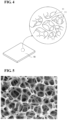
- FIG. 4 schematically shows an example of metal porous-body sheet 10. As shown in FIG. 4 , metal porous-body sheet 10 has a sheet-like shape.
- FIG. 5 shows a cross-sectional photograph of an example of metal porous-body sheet 10.
- FIG. 6 schematically shows an inner portion structure of an example of metal porous-body sheet 10.
- FIG. 7 shows a schematic cross-sectional view of metal porous-body sheet 10 taken along line VII-VII in FIG. 6 .
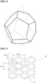
- FIG. 8 shows a schematic view of a unit cell structure of the metal porous body defined by a skeleton 11 of metal porous-body sheet 10.
- skeleton 11 of metal porous-body sheet 10 is typically constituted by a skeleton body 11a made of a metal or an alloy, and an inner portion 1 1b of skeleton 11 is hollow. That is, skeleton 11 has skeleton body 11a and inner portion 11b defined by skeleton body 11a.
- skeleton 11 has a hollow cylindrical shape.
- Skeleton body 11a has a triangular shape in a cross-sectional view intersecting an extending direction (refer to FIG. 7 ). The triangular shape need not be a mathematically exact triangular shape. Skeleton 11 may be solid.
- pore portion 12 formed by skeleton 11 is an interconnected pore formed by connecting the cells (refer to FIG. 8 ) modeled as a regular dodecahedron from the surface to the inner portion of metal porous-body sheet 10.
- the diameter of the circumscribed sphere of the dodecahedral structure (shown by the one-dot chain line in FIG. 8 ) is regarded as a pore diameter of pore portion 12 in the metal porous body.
- the average value of the pore diameters of the pore portions in the metal porous body is referred to as an average pore diameter.
- the average pore diameter of metal porous-body sheet 10 is not particularly limited, and may be appropriately changed in accordance with the size of bubbles generated when water electrolysis is performed using electrode 30.
- the average pore diameter of metal porous-body sheet 10 may be, for example, 400 ⁇ m to 1000 ⁇ m, 500 ⁇ m to 850 ⁇ m in another embodiment, and 600 ⁇ m to 850 ⁇ m in still another embodiment.
- a porosity of metal porous-body sheet 10 may be, for example, 70% to 98%, 80% to 98%, or 90% to 98%.
- the porosity of metal porous-body sheet 10 can be adjusted by, for example, a method of rolling the metal porous-body sheet.
- a thickness of metal porous-body sheet 10 may be appropriately selected in accordance with the size of electrode 30.
- the thickness of metal porous-body sheet 10 may be 0.5 mm to 2.0 mm.
- the thicknesses of metal porous-body sheet 10 can be measured with a digital thickness gauge, for example.
- Skeleton body 11a is formed of a metal material.
- the metal material is any metal material as long as it is stable to an aqueous solution used in water electrolysis.
- Examples of such a metal material include nickel (Ni) and nickel alloy.
- An example of the nickel alloy includes an alloy containing nickel (Ni) as a main component and cobalt (Co) or zinc (Zn) as an additive component in which these components are alloyed.
- the expression of "containing nickel as a main component" means that nickel is the most abundant component in skeleton 11.
- Metallic support body 20 is any metallic support body as long as it has a plurality of through holes 21 extending through two surfaces of metallic support body 20, and for example, an expand metal or a punching metal may be preferably used.
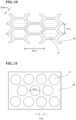
- FIG. 9 and FIG. 10 show examples of the structures of metallic support body 20 which is made of an expand metal.
- FIG. 11 to FIG. 13 show examples of the structures of metallic support body 20 which is made of a punching metal.
- Metallic support body 20 shown in FIG. 9 continuously has rhombic through holes 21 in a staggered pattern, and is constituted by strands around through holes 21.
- a thickness of the strands is 0.8 mm.
- the rhombus constituting each of through holes 21 is horizontally long, the diagonal in a lateral direction is about 8 mm, and the diagonal in the vertical direction is about 4 mm.
- machined holes 16 can be disposed at the upper half positions of the diagonal lines in the vertical direction of through holes 21.
- Metallic support body 20 shown in FIG. 10 continuously has hexagonal through holes 21 in a staggered pattern, and is constituted by strands around through holes 21.
- the thickness of the strands is 0.8 mm.
- the hexagon constituting each of through holes 21 is horizontally long, the diagonal in the lateral direction is about 8 mm, and the distance between two sides extending in the lateral direction is about 4 mm.
- machined holes 16 can be disposed at positions above the diagonal line in the lateral direction of through holes 21.
- Metallic support body 20 shown in FIG. 11 is a metallic plate in which circular through holes 21 having a diameter of 4 mm are formed in a staggered pattern.
- the distance between the centers of through holes 21 adjacent to each other in the lateral direction is about 5 mm. That is, through holes 21 are formed so that the metallic portion is approximately 1 mm long.
- machined holes 16 can be disposed at the upper half positions of the diameters of through holes 21 in the vertical direction.
- hexagonal through holes 21 are formed in a metal plate in a staggered pattern.
- the distance between two sides extending in the lateral direction of through holes 21 is about 4 mm, and the metallic portion having a length of about 1 mm is present between through holes 21 adjacent to each other in the vertical direction.
- machined holes 16 can be disposed at positions above the diagonal line in the lateral direction of through holes 21.
- elliptical through holes 21 are formed in a metal plate in a staggered pattern.
- a major axis of the ellipse is 4 mm, and a minor axis of the ellipse is 2 mm.
- the metallic portion having a length of 1 mm is present between through holes 21 adjacent to each other in the lateral direction.
- the centers of through holes 21 adjacent to each other in an oblique direction are shifted from each other by 2.5 mm in both the lateral direction and the vertical direction.
- machined holes 16 can be disposed at the upper half positions of the minor axes of through holes 21 in the vertical direction.
- Metallic support body 20 is any metallic support body as long as it is stable to an aqueous solution used in water electrolysis.
- the surface of metal support body 20 may be made of nickel or a nickel alloy.
- An example of metallic support body 20 whose surface is made of nickel or a nickel alloy includes, for example, a metallic support body whose surface is plated with nickel or a nickel alloy.
- An example of the nickel alloy includes an alloy containing nickel (Ni) as a main component and cobalt (Co) or zinc (Zn) as an additive component in which these components are alloyed, as in metal porous-body sheet 10.
- the expression of containing nickel as a main component means that nickel is the most abundant component in the nickel alloy.
- a water electrolysis apparatus includes electrode 30 according to the embodiment of the present disclosure.
- FIG. 14 shows a schematic view of an example of a water electrolysis apparatus 40 according to the embodiment of the present disclosure.
- Water electrolysis apparatus 40 is an apparatus for generating, for example, hydrogen gas (H 2 ) and oxygen-gas (O 2 ).
- H 2 hydrogen gas
- O 2 oxygen-gas
- water electrolysis apparatus 40 has electrodes 30 on both sides of a diaphragm 41.
- Each of electrodes 30 is constituted by metal porous-body sheet 10 and metallic support body 20 as described above, and is disposed so that the main surface of metal porous-body sheet 10 is in contact with diaphragm 41.
- Each of electrodes 30 is electrically connected to a negative electrode 42, a positive electrode 43, or a bipolar plate 44 via a plate member 45.
- Plate member 45 can maintain a space for facilitating discharge of bubbles (gas) generated by water electrolysis. In this space, convection of an aqueous solution occurs.
- a plate spring can be used as plate member 45.
- Water electrolysis apparatus 40 shown in FIG. 14 is formed by electrically connecting two unit cells.
- the water electrolysis apparatus according to the embodiment of the present disclosure is not limited to this configuration, and more unit cells may be electrically connected.
- Electrode 30 disposed between diaphragm 41 and negative electrode 42 is a hydrogen evolution electrode.
- electrode 30 disposed between diaphragm 41 and positive electrode 43 is an oxygen evolution electrode.
- Electrode 30 according to the embodiment of the present disclosure is used for at least one of the hydrogen evolution electrode or the oxygen evolution electrode. Both the hydrogen evolution electrode and the oxygen evolution electrode may be electrodes 30 according to the embodiments of the present disclosure.
- Diaphragm 41 allows hydrogen ions (H + ) or hydroxide ions (OH - ) to permeate therethrough.
- Diaphragm 41 which has low gas permeability and low electron conductivity is used.
- diaphragm 41 for example, an ion exchange membrane, a porous diaphragm, or a cloth is used.
- Diaphragm 41 may be a film formed of, for example, a hydrophilic polyethylene nonwoven fabric.
- an alkaline aqueous solution 47 is supplied from below as indicated by the arrows.
- alkaline aqueous solution 47 as an electrolyte is filled in each of spaces partitioned by diaphragm 41 and negative electrode 42, diaphragm 41 and bipolar plate 44, and diaphragm 41 and positive electrode 43.
- alkaline aqueous solution 47 for example, a potassium hydroxide aqueous solution (KOH) may be used.
- a voltage is applied to negative electrode 42 and positive electrode 43.
- water in the alkaline aqueous solution is reduced at electrodes 30 on a side of negative electrode 42, and hydrogen gas 49 is generated.
- Hydrogen gas 49 generated at electrodes 30 is discharged together with the alkaline aqueous solution as indicated by the arrows in the figure.
- hydroxide ions in the alkaline aqueous solution permeate through diaphragm 41 and move from electrodes 30 on the side of negative electrode 42 toward positive electrode 43.
- the hydroxide ions moving toward positive electrode 43 are oxidized at electrodes 30 on the side of the positive electrode.
- oxygen gas 48 is generated at electrodes 30 on the side of positive electrode 43.
- Oxygen gas 48 generated at electrodes 30 on the side of positive electrode 43 is discharged together with the alkaline aqueous solution as indicated by the arrows in the figure.
- water electrolysis apparatus 40 generates hydrogen gas and oxygen gas.
- Water electrolysis apparatus 40 may be an apparatus for generating chlorine gas (Ch), hydrogen gas, and a sodium hydroxide (NaOH) aqueous solution.
- a sodium chloride (NaCl) aqueous solution is used as an electrolyte.
- FIG. 15 schematically shows an example of a simplified water electrolysis apparatus 50 according to the embodiment of the present disclosure.
- Simplified water electrolysis apparatus 50 is an apparatus for generating, for example, a hydrogen gas (H 2 ) and oxygen-gas (O 2 ).
- the up-and-down direction on the plane of the paper of FIG. 15 corresponds to the direction of gravity.
- simplified water electrolysis apparatus 50 includes electrodes 30, diaphragm 41, plates 51, plate members 45, a negative-electrode connection line 52, a positive-electrode connection line 53, and a container 55.
- a potassium hydroxide solution is stored as an electrolyte 54 in container 55.
- Electrodes 30, diaphragm 41, plates 51 and plate members 45 are immersed in electrolyte 54.
- Each of electrodes 30 is an electrode according to the embodiment of the present disclosure described above, and is constituted by metal porous-body sheet 10 and metallic support body 20.
- metal porous-body sheet 10 is in contact with diaphragm 41, and metallic support body 20 is positioned closer to each of plates 51.
- Plates 51 are formed of, for example, a resin material.
- Plate members 45 are disposed between plates 51 and metallic support bodies 20 included in electrodes 30.
- plate members 45 for example, plate springs can be used. Plates 51 that sandwich diaphragm 41 and are disposed on both sides of diaphragm 41 are fixed to each other by, for example, screwing. As a result, metal porous-body sheet 10 included in each of electrodes 30 is pressed against diaphragm 41.
- Negative-electrode connection line 52 is electrically connected to metal porous-body sheet 10 included in one of electrodes 30.
- Positive-electrode connection line 53 is electrically connected to metal porous-body sheet 10 located opposite to metal porous-body sheet 10, to which negative-electrode connection line 52 is connected, with respect to diaphragm 41.
- Negative-electrode connection line 52 and positive-electrode connection line 53 are electrically connected to a power source (not shown) outside simplified water electrolysis apparatus 50.
- Negative-electrode connection line 52 and positive-electrode connection line 53 are formed of, for example, platinum (Pt).
- each of electrodes 30 had a configuration in which metallic support body 20 shown in FIG. 9 was combined with metal porous-body sheet 10 provided with machined holes 16 which extended through metal porous-body sheet 10 and had a diameter of 2.0 mm (aperture ratio: 19%).
- the width of through hole 21 was 8 mm
- the length of electrode 30 in the vertical direction was 100 mm.
- the simulations were performed by changing the positional relationship between machined holes 16 and through holes 21.
- the positional relationship between machined holes 16 and through holes 21 was set to the following four cases (1) to (4).
- (1) The center of each of machined holes 16 was shifted 1 mm above the center of each of through holes 21.
- the center of each of machined holes 16 was aligned with the center of each of through holes 21.
- (3) The center of each of machined holes 16 was shifted at random from the center of each of through holes 21.
- (4) The center of each of machined holes 16 was shifted 1 mm below the center of each of through holes 21.
- the electrode according to the embodiment of the present disclosure in which the center of each of machined holes 16 were shifted 1 mm above the center of each of through holes 21, which is the type (1) above, had the lowest gas volume fraction of 40%, and the bubbles were rapidly discharged. Furthermore, the effective surface area ratio was the highest at 135%. The effective surface area ratio was calculated as a relative value, taking the effective surface area ratio of the metal porous-body sheet without machined holes 16 as 100%.
- the electrode according to the embodiment of the present disclosure in which the center of each of machined holes 16 were shifted 1 mm above the center of each of through holes 21 had the lowest gas volume fraction of 46% and the highest effective surface area ratio of 134%.
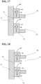
- FIG. 17 is a schematic view showing a partial section of electrode 30 in the case where the center of each of machined holes 16 are shifted above the center of each of through holes 21.
- bubbles (gas) generated in metal porous-body sheet 10 cannot permeate through diaphragm 41, and thus, the bubbles move upward in the direction of gravity or toward metallic support body 20 through pore portion 12 of metal porous-body sheet 10.
- the bubbles moving from below in the direction of gravity gather above metal porous-body sheet 10 in the direction of gravity, and many bubbles are discharged into machined holes 16 or through holes 21 as indicated by arrows in the figure.
- electrode 30 according to the embodiment of the present disclosure has a high bubble discharge property.
- FIG. 18 shows a schematic view of a partial cross section of the electrode in the case where the center of each of machined holes 16 is aligned with the center of each of through holes 21.
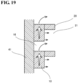
- FIG. 19 is a schematic view of a partial cross section of the electrode in the case where the center of each of machined holes 16 is shifted below the center of each of through holes 21.
- the discharge of bubbles is blocked by metallic support body 20 at a portion where the bubbles moving from below in the direction of gravity gather to a medium extent.
- the discharge of bubbles is blocked by metallic support body 20 at a portion where many bubbles moving from below in the direction of gravity gather.
- the influence of blocking the discharge of bubbles by metallic support body 20 is large for the electrodes shown in FIG. 18 and FIG. 19 , resulting in a large gas volume fraction and a small effective surface area ratio.
- Celmet #8 (Celmet is a trade name) made of nickel manufactured by Sumitomo Electric Industries, Ltd. was prepared.
- the size of the metal porous-body sheet was 50 mm in width (horizontal) and 120 mm in length (vertical).
- the aperture ratio of metal porous-body sheet 10 was 11%, and the porosity thereof was 93%.
- metallic support body 20 the expand metal shown in FIG. 9 was prepared.
- the Cermet and the expand metal were disposed such that the center of each of machined holes 16 was shifted 1mm above the center of each of through holes 21, thereby forming an electrode No. 1.
- a metal mesh (50 mesh) made of nickel was prepared as a metal porous-body sheet.
- the metallic mesh used had a wire diameter of 0.15 mm, and was manufactured by The Nilaco Corporation. This metallic mesh was combined with the expand metal (metallic support body 20) used in Example 1 to form electrode No. 2.
- Celmet #8 (Celmet is a trade name) made of nickel manufactured by Sumitomo Electric Industries, Ltd. was prepared.
- This metal porous-body sheet was combined with the expand metal (metallic support body 20) used in Example 1 to form electrode No. 3. Machined holes 16 were not formed.
- An electrode No. 4 was formed in the same manner as in Example 1 except that the center of each of machined holes 16 was aligned with the centers of through holes 21.
- An electrode No. 5 was formed in the same manner as in Example 1 except that the center of each of machined holes 16 was shifted 1 mm below the center of each of through holes 21 by a portion.
- Water electrolysis was performed using the electrodes No. 1 to No. 5 prepared in Example 1 and Comparative Examples 1 to 4.
- the water electrolysis experiments were conducted using simplified water electrolysis apparatus 50 shown in FIG. 15 .
- the aqueous solution used was a 7 mol% potassium hydrate aqueous solution.
- the temperature (at a cell supply inlet) of the electrolyte (aqueous solution) was 63°C.
- Zirfon Perl UTP500 manufactured by AGFA was used as diaphragm 41.
- the current was held for 5 minutes at each current value, and the electrolysis voltage was measured from the high current side.
- Table 2 and FIG. 20 The results are shown in Table 2 and FIG. 20 . In FIG.
- a vertical axis represents a cell voltage (unit: V), and a horizontal axis represents a current density (unit: mA/cm 2 ).
- Current density mA/cm 2
- Electrolysis voltage V
- Electrode No. 1 Electrode No. 2
- Electrode No. 3 Electrode No. 4
- Electrode No. 5 1000 2.503 2.590 2.583 2.543 2.580 800 2.426 2.493 2.499 2.475 2.502 600 2.339 2.391 2.411 2.397 2.414 400 2.240 2.275 2.305 2.299 2.309 200 2.108 2.119 2.161 2.165 2.162 100 2.009 2.006 2.045 2.057 2.046 50 1.926 1.923 1.958 1.970 1.966
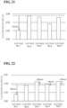
- electrolysis voltages (V) at a current density of 1000 mA/cm 2 are shown in Table 3 and FIG. 21.
- the electrolysis voltages (V) at a current density of 600 mA/cm 2 are shown in Table 3 and FIG. 22.
- electrode 30 electrode No. 1
- the electrolysis voltage was able to be reduced. This is because the bubbles generated at the electrode can be efficiently discharged as described above, and the electrode has high reactivity.
Landscapes
- Chemical & Material Sciences (AREA)
- Engineering & Computer Science (AREA)
- Chemical Kinetics & Catalysis (AREA)
- Electrochemistry (AREA)
- Materials Engineering (AREA)
- Metallurgy (AREA)
- Organic Chemistry (AREA)
- Inorganic Chemistry (AREA)
- Electrodes For Compound Or Non-Metal Manufacture (AREA)
- Electrolytic Production Of Non-Metals, Compounds, Apparatuses Therefor (AREA)
Abstract
Description
- The present disclosure relates to an electrode and a water electrolysis apparatus. This application claims priority based on
Japanese Patent Application No. 2021-211157 filed on December 24, 2021 - Patent Literature 1 (PTL 1:
Japanese National Patent Publication No. 2005-536639 PTL 1 uses a wire mesh. Patent Literature 2 (PTL 2:Japanese Examined Patent Publication No. S61-57397 PTL 2. Patent Literature 3 (PTL 3:WO 2021/153406 ) discloses a metal porous-body sheet, an electrode using the same, and a water electrolysis apparatus.PTL 3 describes that a metal porous-body sheet having a skeleton of a three-dimensional network structure and having a plurality of holes in a main surface is used for the electrode. -
- PTL 1:
Japanese National Patent Publication No. 2005-536639 - PTL 2:
Japanese Examined Patent Publication No. S61-57397 - PTL 3:
WO 2021/153406 - An electrode according to an aspect of the present disclosure includes a metal porous-body sheet formed of a metal porous body having a skeleton with a three-dimensional network structure and a metallic support body having a plate shape and disposed on one main surface of the metal porous-body sheet. The one main surface has a plurality of machined holes each formed perpendicularly to the one main surface, and at least some of the plurality of machined holes are disposed at equal intervals. The metallic support body has a plurality of through holes extending between two surfaces of the metallic support body, and at least some of the plurality of through holes are disposed at equal intervals. The metal porous-body sheet and the metallic support body are disposed such that a center of each of the some of the plurality of machined holes and a center of each of the some of the plurality of through holes are shifted from each other in one direction in plan view.
-
-
FIG. 1 is a schematic plan view of an example of anelectrode 30 according to an embodiment of the present disclosure. -
FIG. 2 is a schematic cross-sectional view ofelectrode 30 taken along line II-II inFIG. 1 . -
FIG. 3 is a schematic plan view of another example ofelectrode 30 according to the embodiment of the present disclosure. -
FIG. 4 is a schematic view of an example of a metal porous-body sheet 10 used forelectrode 30 according to the embodiment of the present disclosure. -
FIG. 5 is a cross-sectional photograph of an example of metal porous-body sheet 10 used forelectrode 30 according to the embodiment of the present disclosure. -
FIG. 6 is a schematic view of an inner portion structure of an example of metal porous-body sheet 10 used forelectrode 30 according to the embodiment of the present disclosure. -
FIG. 7 is a schematic cross-sectional view of metal porous-body sheet 10 taken along line VII-VII inFIG. 6 . -
FIG. 8 is a schematic view showing a unit cell structure of a metal porous body defined by askeleton 11 of metal porous-body sheet 10. -
FIG. 9 is a schematic view showing an example of a structure of ametallic support body 20 which is made of an expand metal. -
FIG. 10 is a schematic view showing another example of the structure ofmetallic support body 20 which is made of an expand metal. -
FIG. 11 is a schematic view showing an example of the structure ofmetallic support body 20 which is made of a punching metal. -
FIG. 12 is a schematic view showing another example of the structure ofmetallic support body 20 which is made of a punching metal. -
FIG. 13 is a schematic view showing still another example of the structure ofmetallic support body 20 which is made of a punching metal. -
FIG. 14 is a schematic view of an example of awater electrolysis apparatus 40 according to the embodiment of the present disclosure. -
FIG. 15 is a schematic view of an example of a simplifiedwater electrolysis apparatus 50 according to the embodiment of the present disclosure. -
FIG. 16 shows simulation results of a gas volume fraction and an effective surface area ratio when water electrolysis is performed using various electrodes. -
FIG. 17 is a schematic view showing a partial cross section of an example ofelectrode 30 in which center of each of machinedholes 16 is shifted above center of each of throughholes 21. -
FIG. 18 is a schematic view showing a partial cross section of an example ofelectrode 30 in which the centers of machinedholes 16 are aligned with the centers of throughholes 21. -
FIG. 19 is a schematic view showing a partial cross section of an example ofelectrode 30 in which the centers of machinedholes 16 are shifted below the centers of throughholes 21. -
FIG. 20 is a graph showing IV characteristics (a vertical axis represents a cell voltage, and a horizontal axis represents a current density) when electrodes prepared in an example and comparative examples are used. -
FIG. 21 is a graph showing an electrolysis voltage at a current density of 1000 mA/cm2 when the electrodes prepared in the example and the comparative examples are used -
FIG. 22 is a graph showing an electrolysis voltage at a current density of 600 mA/cm2 when the electrodes prepared in the example and the comparative examples are used. - The wire mesh used in the electrode structure described in
PTL 1 has a small surface area. Thus, when the electrode structure described inPTL 1 is used for water electrolysis, an electrolysis voltage becomes high. - The metal porous body used in the electrode for water electrolysis described in
PTL 2 has a large surface area. However, gas bubbles generated by water electrolysis are likely to adhere to the inner portion of the metal porous body used in the electrode for water electrolysis described inPTL 2. Since a portion to which the bubbles adhere does not contribute to the electrolytic reaction, the metal porous body used in the electrode for water electrolysis described inPTL 2 cannot reduce the electrolysis voltage during water electrolysis even when the surface area is large. - The metal porous-body sheet used in the electrode described in
PTL 3 has a large surface area and a plurality of holes provided in the main surface, and thus, it is expected that the gas bubbles generated by water electrolysis are easily discharged to the outside. However, as a result of intensive research, the present inventors have found that, depending on a positional relationship of the metallic support body disposed on the main surface of the metal porous-body sheet, the bubbles generated by water electrolysis are sometimes difficult to be discharged from a pore portion of the metal porous-body sheet. - An object of the present disclosure is to provide an electrode that can easily discharge gas bubbles generated at the electrode during water electrolysis and reduce the electrolysis voltage, and a water electrolysis apparatus using the electrode.
- According to the present disclosure, it is possible to provide an electrode that can easily discharge gas bubbles generated at the electrode during water electrolysis and reduce the electrolysis voltage, and a water electrolysis apparatus using the electrode.
- First, embodiments of the present disclosure will be listed and described. (1) An electrode according to an aspect of the present disclosure includes a metal porous-body sheet formed of a metal porous body having a skeleton with a three-dimensional network structure and a metallic support body having a plate shape and disposed on one main surface of the metal porous-body sheet. The one main surface has a plurality of machined holes each formed perpendicularly to the one main surface, and at least some of the plurality of machined holes are disposed at equal intervals. The metallic support body has a plurality of through holes extending between two surfaces of the metallic support body, and at least some of the plurality of through holes are disposed at equal intervals. The metal porous-body sheet and the metallic support body are disposed such that a center of each of the some of the plurality of machined holes and a center of each of the some of the plurality of through holes are shifted from each other in one direction in plan view. According to the aspect of the disclosure described in the above (1), it is possible to provide an electrode that can easily discharge gas bubbles generated at the electrode during water electrolysis and thus reduce an electrolysis voltage.
- (2) The electrode according to the above (1), a maximum diameter of the plurality of machined holes may be 0.5 mm to 3.5 mm. According to the aspect of the disclosure described in the above (2), it is possible to provide an electrode that can easily discharge gas bubbles generated at the electrode during water electrolysis.
- (3) The electrode according to the above (1) or (2), the number of the plurality of machined holes may be 1/3 times to 4 times the number of the plurality of through holes. According to the aspect of the disclosure described in the above (3), it is possible to provide an electrode that can easily discharge gas bubbles generated at the electrode during water electrolysis.
- (4) The electrode according to any one of the above (1) to (3), the plurality of machined holes of the metal porous-body sheet may extend through two surfaces of the metal porous-body sheet. According to the aspect of the disclosure described in the above (4), it is possible to provide an electrode that can more easily discharge gas bubbles generated at the electrode during water electrolysis and thus further reduce the electrolysis voltage.
- (5) The electrode according to any one of the above (1) to (4), the metal porous-body sheet and the metallic support body may be disposed such that a center of each of all of the plurality of machined holes and a center of each of all of the plurality of through holes are shifted from each other in one direction in plan view. According to the aspect of the disclosure described in the above (5), it is possible to provide an electrode that can more easily discharge gas bubbles generated at the electrode during water electrolysis and thus further reduce the electrolysis voltage.
- (6) The electrode according to any one of the above (1) to (5), a ratio of a sum of areas of the plurality of machined holes to a total area of main surface of metal porous-body sheet (a total area of main surface of metal porous-body sheet/a sum of areas of the plurality of machined holes × 100) may be 5% to 35%. According to the aspect of the disclosure described in the above (6), it is possible to provide an electrode that can easily discharge gas bubbles generated at the electrode during water electrolysis and has high reactivity.
- (7) The electrode according to any one of the above (1) to (6), the metallic support body may be made of an expand metal or a punching metal. According to the aspect of the disclosure described in the above (7), it is possible to provide an electrode that can easily discharge gas bubbles generated at the electrode during water electrolysis.
- (8) The electrode according to any one of the above (1) to (7), a surface of the metal porous-body sheet may be made of nickel or a nickel alloy. According to the aspect of the disclosure described in the above (8), it is possible to provide an electrode that has high reactivity in water electrolysis.
- (9) The electrode according to any one of the above (1) to (8), a surface of the metallic support body may be made of nickel or a nickel alloy. According to the aspect of the disclosure described in the above (9), it is possible to provide an electrode that can easily discharge gas bubbles generated at the electrode during water electrolysis.
- (10) A water electrolysis apparatus according to the embodiment of the present disclosure includes the electrode according to any one of the above (1) to (9). According to the aspect of the disclosure described in the above (10), it is possible to provide a water electrolysis apparatus that can easily discharge gas bubbles generated at the electrode during water electrolysis and reduce the electrolysis voltage.
- (11) In the water electrolysis apparatus of an electrode according to the above (10), the metal porous-body sheet and the metallic support body may be disposed such that a center of each of the some of the plurality of machined holes is positioned above a center of each of the some of the plurality of through holes in a direction of gravity. According to the aspect of the disclosure described in the above (11), it is possible to provide a water electrolysis apparatus that can easily discharge gas bubbles generated at the electrode during water electrolysis and reduce the electrolysis voltage.
- Specific examples of the electrode and the water electrolysis apparatus according to the embodiment of the present disclosure will be described in more detail below. The present disclosure is not limited to these examples, but is defined by the claims, and is intended to include all modifications within the meaning and scope equivalent to the claims.
- Hereinafter, each configuration of the electrode according to the embodiment of the present disclosure will be described with reference to the drawings as needed.
FIG. 1 schematically shows an example ofelectrode 30 according to the embodiment of the present disclosure. As shown inFIG. 1 ,electrode 30 includes a metal porous-body sheet 10 and a plate-shapedmetallic support body 20.Metallic support body 20 is disposed on one main surface of metal porous-body sheet 10. - Metal porous-
body sheet 10 is formed of a metal porous body having a skeleton with a three-dimensional network structure and a pore portion formed by the skeleton. The one main surface of metal porous-body sheet 10, which is in contact withmetallic support body 20, is provided with a plurality of machinedholes 16 formed perpendicular to the one main surface. Although the plurality of machinedholes 16 are disposed at equal intervals, all of the plurality of machinedholes 16 may be disposed at equal intervals, or some of the plurality of machinedholes 16 may be disposed at equal intervals. In addition, the plurality of machinedholes 16 are partial recesses or penetrations formed in the one main surface of the metal porous-body sheet, and are different from the pore portion which is a constituent element of metal porous-body sheet 10. - Machined holes 16 may extend through two surfaces of metal porous-
body sheet 10. Since the plurality of machinedholes 16 are formed so as to extend through the two surfaces of metal porous-body sheet 10, more bubbles can be rapidly discharged fromelectrode 30 through machinedholes 16. Since many bubbles are rapidly discharged fromelectrode 30 during water electrolysis, a larger portion of metal porous-body sheet 10 used forelectrode 30 can contribute to the electrolytic reaction. That is, the advantage of the large surface area of metal porous-body sheet 10 can be utilized. - Machined holes 16 may have any shape, and may have a circular shape, an elliptical shape, or a polygonal shape. The diameter of machined
holes 16 is not particularly limited, but as an example, a maximum diameter of machinedholes 16 may be 0.5 mm to 3.5 mm, may be 0.7 mm to 3.0 mm, or may be 0.8 mm to 2.7 mm. -
Metallic support body 20 is provided with a plurality of throughholes 21 extending through the two surfaces of the metallic support body. In the example shown inFIG. 1 ,metallic support body 20 is made of an expand metal, and has a shape in which rhombic throughholes 21 are continuously disposed in a staggered pattern. - As described above,
metallic support body 20 is disposed on the main surface of metal porous-body sheet 10 where the plurality of machinedholes 16 are formed.Electrode 30 shown inFIG. 1 has a structure in whichmetallic support body 20 is disposed in front of metal porous-body sheet 10 on the plane of the paper.FIG. 2 is a cross-sectional view ofelectrode 30 taken along line II-II inFIG. 1 . As shown inFIG. 1 andFIG. 2 , metal porous-body sheet 10 andmetallic support body 20 are disposed such that the center of each of at least some of the plurality of machinedholes 16 of metal porous-body sheet 10 and the center of each of at least some of the plurality of throughholes 21 ofmetallic support body 20 of are shifted from each other in one direction in plan view. In addition, the center of each of the at least some of the plurality of machinedholes 16 of metal porous-body sheet 10 is disposed so as to be present inside each of the at least some of the plurality of throughholes 21 ofmetallic support body 20 in plan view. In the water electrolysis apparatus,electrode 30 may be disposed and used so that the center of each of machinedholes 16 seen from each of throughholes 21 is positioned above the center of each of throughholes 21 in a direction of gravity. The expression of "being positioned above" means that the center of each of machinedholes 16 and the center of each of throughholes 21 is shifted from each other in a vertical direction whenelectrode 30 is viewed from the main surface on a side of metallic support body 20 (that is, the state as shown inFIG. 1 ). In addition, the vertical direction refers to the direction of gravity when water electrolysis is performed usingelectrode 30. - In
electrode 30 according to the embodiment of the present disclosure, as shown inFIG. 1 , the center of each of the at least some of the plurality of machinedholes 16 is positioned above the center of each of the some of the plurality of throughholes 21. For example, inelectrode 30 shown inFIG. 1 , the center of each of machinedholes 16 in a row adjacent to a row of machinedholes 16 each positioned above the center of each of throughholes 21 is not positioned above the center of each of throughholes 21. However, in order to more quickly discharge bubbles generated during water electrolysis, the center of each of all ofmachined holes 16 may be positioned above the center of each of throughholes 21 as inelectrode 30 shown inFIG. 3 . - A diameter of machined
holes 16 is not particularly limited, and may be appropriately selected in accordance with the size of throughholes 21. For example, the diameter of machinedholes 16 may be smaller than the diameter of throughholes 21 in a vertical direction. - The number of the plurality of machined
holes 16 is not particularly limited, and may be appropriately selected in accordance with the number of the plurality of throughholes 21. For example, the number of the plurality of machinedholes 16 may be 1/3 times to 4 times the number of the plurality of throughholes 16, or the number of the plurality of machinedholes 16 may be equal to the number of the plurality of throughholes 16. - In
electrode 30 according to the embodiment of the present disclosure, a ratio of a sum of areas of the plurality of machinedholes 16 to a total area of the main surface of metal porous-body sheet 10 (hereinafter, referred to as an "aperture ratio") may be 5% to 35%. The aperture ratio can be calculated by the following equation: "the total area of the main surface of metal porous-body sheet 10"/"the sum of the areas of the plurality of machinedholes 16" × 100. - When the aperture ratio of metal porous-
body sheet 10 is increased, the discharge performance of bubbles generated whenelectrode 30 is used for water electrolysis can be increased, and the electrolysis voltage can be decreased. On the other hand, when the aperture ratio of metal porous-body sheet 10 is too large, the surface area of metal porous-body sheet 10 is reduced, and the reactivity ofelectrode 30 may be deteriorated. Thus, the aperture ratio of metal porous-body sheet 10 may be 5% to 35%, 7% to 32%, or 10% to 30%. - As described above, metal porous-
body sheet 10 is formed of a metal porous body having a skeleton with a three-dimensional network structure.FIG. 4 schematically shows an example of metal porous-body sheet 10. As shown inFIG. 4 , metal porous-body sheet 10 has a sheet-like shape.FIG. 5 shows a cross-sectional photograph of an example of metal porous-body sheet 10.FIG. 6 schematically shows an inner portion structure of an example of metal porous-body sheet 10.FIG. 7 shows a schematic cross-sectional view of metal porous-body sheet 10 taken along line VII-VII inFIG. 6 .FIG. 8 shows a schematic view of a unit cell structure of the metal porous body defined by askeleton 11 of metal porous-body sheet 10. - As shown in
FIG. 6 and FIG. 7 ,skeleton 11 of metal porous-body sheet 10 is typically constituted by askeleton body 11a made of a metal or an alloy, and aninner portion 1 1b ofskeleton 11 is hollow. That is,skeleton 11 hasskeleton body 11a andinner portion 11b defined byskeleton body 11a. Thus,skeleton 11 has a hollow cylindrical shape.Skeleton body 11a has a triangular shape in a cross-sectional view intersecting an extending direction (refer toFIG. 7 ). The triangular shape need not be a mathematically exact triangular shape.Skeleton 11 may be solid. Furthermore,pore portion 12 formed byskeleton 11 is an interconnected pore formed by connecting the cells (refer toFIG. 8 ) modeled as a regular dodecahedron from the surface to the inner portion of metal porous-body sheet 10. The diameter of the circumscribed sphere of the dodecahedral structure (shown by the one-dot chain line inFIG. 8 ) is regarded as a pore diameter ofpore portion 12 in the metal porous body. The average value of the pore diameters of the pore portions in the metal porous body is referred to as an average pore diameter. - The average pore diameter of metal porous-
body sheet 10 is not particularly limited, and may be appropriately changed in accordance with the size of bubbles generated when water electrolysis is performed usingelectrode 30. The average pore diameter of metal porous-body sheet 10 may be, for example, 400 µm to 1000 µm, 500 µm to 850 µm in another embodiment, and 600 µm to 850 µm in still another embodiment. - The average pore diameter of metal porous-
body sheet 10 is calculated by the following Formula [1] after observing at least 10 fields of view of the main surface of metal porous-body sheet 10 with a microscope or the like and determining an average number (nc) ofpore portions 12 per inch (25.4 mm = 25400 µm).
pore portions 12 is measured in accordance with the method for determining the number of pores (number of cells) of flexible cellular polymeric materials according to JIS K6400-1:2004 Annex 1 (informative) (except for the specification of the dimensions of the test piece). - A porosity of metal porous-
body sheet 10 may be, for example, 70% to 98%, 80% to 98%, or 90% to 98%. The porosity of metal porous-body sheet 10 can be adjusted by, for example, a method of rolling the metal porous-body sheet. The porosity of metal porous-body sheet 10 is defined by the following Formula [1]. However, the volume of machinedholes 16 is not included in Vp.
- Mp: Mass [g] of metal porous-body sheet
- Vp: Volume [cm3] determined by external shape of metal porous-body sheet
- dp: Density of metal constituting metal porous-body sheet [g / cm3]
- A thickness of metal porous-
body sheet 10 may be appropriately selected in accordance with the size ofelectrode 30. For example, the thickness of metal porous-body sheet 10 may be 0.5 mm to 2.0 mm. The thicknesses of metal porous-body sheet 10 can be measured with a digital thickness gauge, for example. -
Skeleton body 11a is formed of a metal material. The metal material is any metal material as long as it is stable to an aqueous solution used in water electrolysis. Examples of such a metal material include nickel (Ni) and nickel alloy. An example of the nickel alloy includes an alloy containing nickel (Ni) as a main component and cobalt (Co) or zinc (Zn) as an additive component in which these components are alloyed. Inskeleton 11, the expression of "containing nickel as a main component" means that nickel is the most abundant component inskeleton 11. -
Metallic support body 20 is any metallic support body as long as it has a plurality of throughholes 21 extending through two surfaces ofmetallic support body 20, and for example, an expand metal or a punching metal may be preferably used.FIG. 9 andFIG. 10 show examples of the structures ofmetallic support body 20 which is made of an expand metal.FIG. 11 to FIG. 13 show examples of the structures ofmetallic support body 20 which is made of a punching metal. -
Metallic support body 20 shown inFIG. 9 continuously has rhombic throughholes 21 in a staggered pattern, and is constituted by strands around throughholes 21. As an example, a thickness of the strands is 0.8 mm. In the example ofmetallic support body 20 shown inFIG. 9 , the rhombus constituting each of throughholes 21 is horizontally long, the diagonal in a lateral direction is about 8 mm, and the diagonal in the vertical direction is about 4 mm. In a case wheremetallic support body 20 is used forelectrode 30, for example, when the diameter of machinedholes 16 formed in metal porous-body sheet 10 is about 2 mm, machinedholes 16 can be disposed at the upper half positions of the diagonal lines in the vertical direction of throughholes 21. -
Metallic support body 20 shown inFIG. 10 continuously has hexagonal throughholes 21 in a staggered pattern, and is constituted by strands around throughholes 21. As inmetallic support body 20 shown inFIG. 9 , the thickness of the strands is 0.8 mm. In the example ofmetallic support body 20 shown inFIG. 10 , the hexagon constituting each of throughholes 21 is horizontally long, the diagonal in the lateral direction is about 8 mm, and the distance between two sides extending in the lateral direction is about 4 mm. In a case wheremetallic support body 20 is used forelectrode 30, as in the case ofmetallic support body 20 shown inFIG. 9 , for example, when the diameter of machinedholes 16 formed in metal porous-body sheet 10 is about 2 mm, machinedholes 16 can be disposed at positions above the diagonal line in the lateral direction of throughholes 21. -
Metallic support body 20 shown inFIG. 11 is a metallic plate in which circular throughholes 21 having a diameter of 4 mm are formed in a staggered pattern. The distance between the centers of throughholes 21 adjacent to each other in the lateral direction is about 5 mm. That is, throughholes 21 are formed so that the metallic portion is approximately 1 mm long. In a case wheremetallic support body 20 is used forelectrode 30, for example, when the diameter of machinedholes 16 formed in metal porous-body sheet 10 is about 2 mm, machinedholes 16 can be disposed at the upper half positions of the diameters of throughholes 21 in the vertical direction. - In
metallic support body 20 shown inFIG. 12 , hexagonal throughholes 21 are formed in a metal plate in a staggered pattern. The distance between two sides extending in the lateral direction of throughholes 21 is about 4 mm, and the metallic portion having a length of about 1 mm is present between throughholes 21 adjacent to each other in the vertical direction. In a case wheremetallic support body 20 is used forelectrode 30, for example, when the diameter of machinedholes 16 formed in metal porous-body sheet 10 is about 2 mm, machinedholes 16 can be disposed at positions above the diagonal line in the lateral direction of throughholes 21. - In
metallic support body 20 shown inFIG. 13 , elliptical throughholes 21 are formed in a metal plate in a staggered pattern. A major axis of the ellipse is 4 mm, and a minor axis of the ellipse is 2 mm. The metallic portion having a length of 1 mm is present between throughholes 21 adjacent to each other in the lateral direction. Furthermore, the centers of throughholes 21 adjacent to each other in an oblique direction are shifted from each other by 2.5 mm in both the lateral direction and the vertical direction. In a case wheremetallic support body 20 is used forelectrode 30, for example, when the diameter of machinedholes 16 formed in metal porous-body sheet 10 is about 2 mm, machinedholes 16 can be disposed at the upper half positions of the minor axes of throughholes 21 in the vertical direction. -
Metallic support body 20 is any metallic support body as long as it is stable to an aqueous solution used in water electrolysis. For example, the surface ofmetal support body 20 may be made of nickel or a nickel alloy. An example ofmetallic support body 20 whose surface is made of nickel or a nickel alloy includes, for example, a metallic support body whose surface is plated with nickel or a nickel alloy. An example of the nickel alloy includes an alloy containing nickel (Ni) as a main component and cobalt (Co) or zinc (Zn) as an additive component in which these components are alloyed, as in metal porous-body sheet 10. The expression of containing nickel as a main component means that nickel is the most abundant component in the nickel alloy. - A water electrolysis apparatus according to the embodiment of the present disclosure includes
electrode 30 according to the embodiment of the present disclosure. Hereinafter, a configuration of a water electrolysis apparatus according to the embodiment of the present disclosure will be described with reference to the drawings as needed.FIG. 14 shows a schematic view of an example of awater electrolysis apparatus 40 according to the embodiment of the present disclosure.Water electrolysis apparatus 40 is an apparatus for generating, for example, hydrogen gas (H2) and oxygen-gas (O2). The up-and-down direction on the plane of the paper ofFIG. 14 corresponds to the direction of gravity. - As shown in
FIG. 14 ,water electrolysis apparatus 40 haselectrodes 30 on both sides of adiaphragm 41. Each ofelectrodes 30 is constituted by metal porous-body sheet 10 andmetallic support body 20 as described above, and is disposed so that the main surface of metal porous-body sheet 10 is in contact withdiaphragm 41. Each ofelectrodes 30 is electrically connected to anegative electrode 42, apositive electrode 43, or abipolar plate 44 via aplate member 45. -
Plate member 45 can maintain a space for facilitating discharge of bubbles (gas) generated by water electrolysis. In this space, convection of an aqueous solution occurs. Asplate member 45, for example, a plate spring can be used. -
Water electrolysis apparatus 40 shown inFIG. 14 is formed by electrically connecting two unit cells. The water electrolysis apparatus according to the embodiment of the present disclosure is not limited to this configuration, and more unit cells may be electrically connected. -
Electrode 30 disposed betweendiaphragm 41 andnegative electrode 42 is a hydrogen evolution electrode. On the other hand,electrode 30 disposed betweendiaphragm 41 andpositive electrode 43 is an oxygen evolution electrode.Electrode 30 according to the embodiment of the present disclosure is used for at least one of the hydrogen evolution electrode or the oxygen evolution electrode. Both the hydrogen evolution electrode and the oxygen evolution electrode may beelectrodes 30 according to the embodiments of the present disclosure. -
Diaphragm 41 allows hydrogen ions (H+) or hydroxide ions (OH-) to permeate therethrough.Diaphragm 41 which has low gas permeability and low electron conductivity is used. Asdiaphragm 41, for example, an ion exchange membrane, a porous diaphragm, or a cloth is used.Diaphragm 41 may be a film formed of, for example, a hydrophilic polyethylene nonwoven fabric. - In
water electrolysis apparatus 40 shown inFIG. 14 , an alkalineaqueous solution 47 is supplied from below as indicated by the arrows. Thus, alkalineaqueous solution 47 as an electrolyte is filled in each of spaces partitioned bydiaphragm 41 andnegative electrode 42,diaphragm 41 andbipolar plate 44, anddiaphragm 41 andpositive electrode 43. As alkalineaqueous solution 47, for example, a potassium hydroxide aqueous solution (KOH) may be used. - During operation of
water electrolysis apparatus 40, a voltage is applied tonegative electrode 42 andpositive electrode 43. As a result, water in the alkaline aqueous solution is reduced atelectrodes 30 on a side ofnegative electrode 42, andhydrogen gas 49 is generated.Hydrogen gas 49 generated atelectrodes 30 is discharged together with the alkaline aqueous solution as indicated by the arrows in the figure. In addition, at this time, hydroxide ions in the alkaline aqueous solution permeate throughdiaphragm 41 and move fromelectrodes 30 on the side ofnegative electrode 42 towardpositive electrode 43. - The hydroxide ions moving toward
positive electrode 43 are oxidized atelectrodes 30 on the side of the positive electrode. As a result,oxygen gas 48 is generated atelectrodes 30 on the side ofpositive electrode 43.Oxygen gas 48 generated atelectrodes 30 on the side ofpositive electrode 43 is discharged together with the alkaline aqueous solution as indicated by the arrows in the figure. As such a reaction continues,water electrolysis apparatus 40 generates hydrogen gas and oxygen gas. -
Water electrolysis apparatus 40 may be an apparatus for generating chlorine gas (Ch), hydrogen gas, and a sodium hydroxide (NaOH) aqueous solution. In this case, a sodium chloride (NaCl) aqueous solution is used as an electrolyte. -
FIG. 15 schematically shows an example of a simplifiedwater electrolysis apparatus 50 according to the embodiment of the present disclosure. Simplifiedwater electrolysis apparatus 50 is an apparatus for generating, for example, a hydrogen gas (H2) and oxygen-gas (O2). The up-and-down direction on the plane of the paper ofFIG. 15 corresponds to the direction of gravity. As shown inFIG. 15 , simplifiedwater electrolysis apparatus 50 includeselectrodes 30,diaphragm 41,plates 51,plate members 45, a negative-electrode connection line 52, a positive-electrode connection line 53, and acontainer 55. A potassium hydroxide solution is stored as anelectrolyte 54 incontainer 55.Electrodes 30,diaphragm 41,plates 51 andplate members 45 are immersed inelectrolyte 54. Each ofelectrodes 30 is an electrode according to the embodiment of the present disclosure described above, and is constituted by metal porous-body sheet 10 andmetallic support body 20. In each ofelectrodes 30, metal porous-body sheet 10 is in contact withdiaphragm 41, andmetallic support body 20 is positioned closer to each ofplates 51.Plates 51 are formed of, for example, a resin material. -
Plate members 45 are disposed betweenplates 51 andmetallic support bodies 20 included inelectrodes 30. Asplate members 45, for example, plate springs can be used.Plates 51 thatsandwich diaphragm 41 and are disposed on both sides ofdiaphragm 41 are fixed to each other by, for example, screwing. As a result, metal porous-body sheet 10 included in each ofelectrodes 30 is pressed againstdiaphragm 41. Negative-electrode connection line 52 is electrically connected to metal porous-body sheet 10 included in one ofelectrodes 30. Positive-electrode connection line 53 is electrically connected to metal porous-body sheet 10 located opposite to metal porous-body sheet 10, to which negative-electrode connection line 52 is connected, with respect todiaphragm 41. Negative-electrode connection line 52 and positive-electrode connection line 53 are electrically connected to a power source (not shown) outside simplifiedwater electrolysis apparatus 50. Negative-electrode connection line 52 and positive-electrode connection line 53 are formed of, for example, platinum (Pt). - In simplified
water electrolysis apparatus 50 shown inFIG. 15 , the volume fraction of hydrogen gas generated atelectrodes 30 was determined by simulation. Each ofelectrodes 30 had a configuration in whichmetallic support body 20 shown inFIG. 9 was combined with metal porous-body sheet 10 provided with machinedholes 16 which extended through metal porous-body sheet 10 and had a diameter of 2.0 mm (aperture ratio: 19%). In the CAE model, the width of throughhole 21 was 8 mm, and the length ofelectrode 30 in the vertical direction was 100 mm. As shown inFIG. 16 , the simulations were performed by changing the positional relationship betweenmachined holes 16 and throughholes 21. - The positional relationship between
machined holes 16 and throughholes 21 was set to the following four cases (1) to (4). (1) The center of each of machinedholes 16 was shifted 1 mm above the center of each of throughholes 21. (2) The center of each of machinedholes 16 was aligned with the center of each of throughholes 21. (3) The center of each of machinedholes 16 was shifted at random from the center of each of throughholes 21. (4) The center of each of machinedholes 16 was shifted 1 mm below the center of each of throughholes 21. - As a result, as shown in
FIG. 16 , it was found that the electrode according to the embodiment of the present disclosure in which the center of each of machinedholes 16 were shifted 1 mm above the center of each of throughholes 21, which is the type (1) above, had the lowest gas volume fraction of 40%, and the bubbles were rapidly discharged. Furthermore, the effective surface area ratio was the highest at 135%. The effective surface area ratio was calculated as a relative value, taking the effective surface area ratio of the metal porous-body sheet without machinedholes 16 as 100%. - The simulation results when the diameter of machined
holes 16 was changed to 1.5 mm (aperture ratio: 11%) are shown in Table 1 below.[Table 1] Electrode where machined holes are shifted 1 mm above Electrode where centers of machined holes are aligned with centers of through holes Electrode where machined holes are not formed Gas volume fraction 46% 54% 64% Effective surface area ratio 134% 114% 100% - As shown in Table 1, even when the diameter of machined
holes 16 was 1.5 mm, the electrode according to the embodiment of the present disclosure in which the center of each of machinedholes 16 were shifted 1 mm above the center of each of throughholes 21 had the lowest gas volume fraction of 46% and the highest effective surface area ratio of 134%. - The results are considered as follows. First,
FIG. 17 is a schematic view showing a partial section ofelectrode 30 in the case where the center of each of machinedholes 16 are shifted above the center of each of throughholes 21. In the electrode shown inFIG. 17 , bubbles (gas) generated in metal porous-body sheet 10 cannot permeate throughdiaphragm 41, and thus, the bubbles move upward in the direction of gravity or towardmetallic support body 20 throughpore portion 12 of metal porous-body sheet 10. At this time, the bubbles moving from below in the direction of gravity gather above metal porous-body sheet 10 in the direction of gravity, and many bubbles are discharged into machinedholes 16 or throughholes 21 as indicated by arrows in the figure. That is, in a portion where the discharge of bubbles is blocked by the contact withmetallic support body 20, the bubbles generated in metal porous-body sheet 10 are not so many, and thus, the influence of blocking the discharge towardmetallic support body 20 is small. Thus, it is considered thatelectrode 30 according to the embodiment of the present disclosure has a high bubble discharge property. - Next,
FIG. 18 shows a schematic view of a partial cross section of the electrode in the case where the center of each of machinedholes 16 is aligned with the center of each of throughholes 21.FIG. 19 is a schematic view of a partial cross section of the electrode in the case where the center of each of machinedholes 16 is shifted below the center of each of throughholes 21. In the case of the electrode shown inFIG. 18 , the discharge of bubbles is blocked bymetallic support body 20 at a portion where the bubbles moving from below in the direction of gravity gather to a medium extent. In the case of the electrode shown inFIG. 19 , the discharge of bubbles is blocked bymetallic support body 20 at a portion where many bubbles moving from below in the direction of gravity gather. As described above, it is considered that the influence of blocking the discharge of bubbles bymetallic support body 20 is large for the electrodes shown inFIG. 18 andFIG. 19 , resulting in a large gas volume fraction and a small effective surface area ratio. - The present disclosure will be described in more detail below based on examples. However, these examples are merely illustrative, and the electrode and the water electrolysis apparatus of the present disclosure are not limited thereto. The scope of the present disclosure is defined by the appended claims, and includes all modifications within the meaning and scope equivalent to the claims.
- As metal porous-
body sheet 10, Celmet #8 (Celmet is a trade name) made of nickel manufactured by Sumitomo Electric Industries, Ltd. was prepared. The size of the metal porous-body sheet was 50 mm in width (horizontal) and 120 mm in length (vertical). Prepared metal porous-body sheet 10 having an average pore diameter of 450 µm, a porosity of 97%, and a thickness of 1.2 mm was rolled to a thickness of 0.5 mm, and then machined holes 16 (holes extending through metal porous-body sheet 10 in a thickness direction) having a diameter of 1.5 mm were formed in metal porous-body sheet 10 in a staggered pattern. As a result, the aperture ratio of metal porous-body sheet 10 was 11%, and the porosity thereof was 93%. Asmetallic support body 20, the expand metal shown inFIG. 9 was prepared. As shown inFIG. 2 , the Cermet and the expand metal were disposed such that the center of each of machinedholes 16 was shifted 1mm above the center of each of throughholes 21, thereby forming an electrode No. 1. - A metal mesh (50 mesh) made of nickel was prepared as a metal porous-body sheet. The metallic mesh used had a wire diameter of 0.15 mm, and was manufactured by The Nilaco Corporation. This metallic mesh was combined with the expand metal (metallic support body 20) used in Example 1 to form electrode No. 2.
- As a metal porous-body sheet, Celmet #8 (Celmet is a trade name) made of nickel manufactured by Sumitomo Electric Industries, Ltd. was prepared. The metal porous-body sheet having an average pore diameter of 450 µm, a porosity of 97%, and a thickness of 1.2 mm was rolled to a thickness of 0.5 mm to obtain a metal porous-body sheet having a porosity of 92%, and the obtained metal porous-body sheet was used. This metal porous-body sheet was combined with the expand metal (metallic support body 20) used in Example 1 to form electrode No. 3. Machined holes 16 were not formed.
- An electrode No. 4 was formed in the same manner as in Example 1 except that the center of each of machined
holes 16 was aligned with the centers of throughholes 21. - An electrode No. 5 was formed in the same manner as in Example 1 except that the center of each of machined
holes 16 was shifted 1 mm below the center of each of throughholes 21 by a portion. - Water electrolysis was performed using the electrodes No. 1 to No. 5 prepared in Example 1 and Comparative Examples 1 to 4. The water electrolysis experiments were conducted using simplified
water electrolysis apparatus 50 shown inFIG. 15 . The aqueous solution used was a 7 mol% potassium hydrate aqueous solution. The temperature (at a cell supply inlet) of the electrolyte (aqueous solution) was 63°C. Zirfon Perl UTP500 manufactured by AGFA was used asdiaphragm 41. The current was held for 5 minutes at each current value, and the electrolysis voltage was measured from the high current side. The results are shown in Table 2 andFIG. 20 . InFIG. 20 , a vertical axis represents a cell voltage (unit: V), and a horizontal axis represents a current density (unit: mA/cm2).[Table 2] Current density (mA/cm2) Electrolysis voltage (V) Electrode No. 1 Electrode No. 2 Electrode No. 3 Electrode No. 4 Electrode No. 5 1000 2.503 2.590 2.583 2.543 2.580 800 2.426 2.493 2.499 2.475 2.502 600 2.339 2.391 2.411 2.397 2.414 400 2.240 2.275 2.305 2.299 2.309 200 2.108 2.119 2.161 2.165 2.162 100 2.009 2.006 2.045 2.057 2.046 50 1.926 1.923 1.958 1.970 1.966 -
[Table 3] Current density (mA/cm2) Electrolysis voltage (V) Electrode No. 1 Electrode No. 2 Electrode No. 3 Electrode No. 4 Electrode No. 5 1000 2.503 2.590 2.583 2.543 2.580 600 2.339 2.391 2.411 2.397 2.414 - As shown in Table 2 and Table 3 and
FIG. 20 to FIG. 22 , when electrode 30 (electrode No. 1) according to the embodiment of the present disclosure was used, the electrolysis voltage was able to be reduced. This is because the bubbles generated at the electrode can be efficiently discharged as described above, and the electrode has high reactivity. -
- 10 metal porous-body sheet
- 11 skeleton
- 11a skeleton body
- 11b inner portion
- 12 pore portion
- 16 machined hole
- 20 metallic support body
- 21 through hole
- 30 electrode
- 40 water electrolysis apparatus
- 41 diaphragm
- 42 negative electrode
- 43 positive electrode
- 44 bipolar plate
- 45 plate member
- 50 simplified water electrolysis apparatus
- 51 plate
- 52 negative-electrode connection line
- 53 positive-electrode connection line
- 54 electrolyte
- 55 container
Claims (11)
- An electrode comprising:a metal porous-body sheet formed of a metal porous body having a skeleton, the skeleton having a three-dimensional network structure; anda metallic support body having a plate shape and disposed on one main surface of the metal porous-body sheet,wherein the one main surface has a plurality of machined holes each formed perpendicularly to the one main surface, and at least some of the plurality of machined holes are disposed at equal intervals,wherein the metallic support body has a plurality of through holes extending between two surfaces of the metallic support body, and at least some of the plurality of through holes are disposed at equal intervals, andwherein the metal porous-body sheet and the metallic support body are disposed such thata center of each of the some of the plurality of machined holes and a center of each of the some of the plurality of through holes are shifted from each other in one direction in plan view.
- The electrode according to claim 1,
wherein a maximum diameter of the plurality of machined holes is 0.5 mm to 3.5 mm. - The electrode according to claim 1 or claim 2,
wherein a number of the plurality of machined holes is 1/3 times to 4 times a number of the plurality of through holes. - The electrode according to any one of claim 1 to claim 3,
wherein the plurality of machined holes extend through two surfaces of the metal porous-body sheet. - The electrode according to any one of claim 1 to claim 4,wherein the metal porous-body sheet and the metallic support body are disposed such thata center of each of all of the plurality of machined holes and a center of each of all of the plurality of through holes are shifted from each other in one direction in plan view.
- The electrode according to any one of claim 1 to claim 5,
wherein an aperture ratio of the metal porous-body sheet is 5% to 35%. - The electrode according to any one of claim 1 to claim 6,
wherein the metallic support body is made of an expand metal or a punching metal. - The electrode according to any one of claim 1 to claim 7,
wherein a surface of the metal porous-body sheet is made of nickel or a nickel alloy. - The electrode according to any one of claim 1 to claim 8,
wherein a surface of the metallic support body is made of nickel or a nickel alloy. - A water electrolysis apparatus comprising:
the electrode according to any one of claim 1 to claim 9. - The water electrolysis apparatus according to claim 10,wherein the metal porous-body sheet and the metallic support body are disposed such thata center of each of the some of the plurality of machined holes is positioned above a center of each of the some of the plurality of through holes in a direction of gravity.
Applications Claiming Priority (2)
| Application Number | Priority Date | Filing Date | Title |
|---|---|---|---|
| JP2021211157 | 2021-12-24 | ||
| PCT/JP2022/031982 WO2023119730A1 (en) | 2021-12-24 | 2022-08-25 | Electrode and water electrolysis device |
Publications (2)
| Publication Number | Publication Date |
|---|---|
| EP4455369A1 true EP4455369A1 (en) | 2024-10-30 |
| EP4455369A4 EP4455369A4 (en) | 2025-08-20 |
Family
ID=86901765
Family Applications (1)
| Application Number | Title | Priority Date | Filing Date |
|---|---|---|---|
| EP22910457.5A Pending EP4455369A4 (en) | 2021-12-24 | 2022-08-25 | ELECTRODE AND WATER ELECTROLYSIS DEVICE |
Country Status (5)
| Country | Link |
|---|---|
| US (1) | US20250034728A1 (en) |
| EP (1) | EP4455369A4 (en) |
| JP (1) | JPWO2023119730A1 (en) |
| CN (1) | CN118382724A (en) |
| WO (1) | WO2023119730A1 (en) |
Families Citing this family (2)
| Publication number | Priority date | Publication date | Assignee | Title |
|---|---|---|---|---|
| CN119948209A (en) * | 2023-08-30 | 2025-05-06 | 富山住友电工株式会社 | Grids, water electrolysis devices and fuel cells |
| NL2036627B1 (en) | 2023-12-21 | 2025-07-07 | Univ Delft Tech | 3D electrode for integrated battery and electrolyser application |
Family Cites Families (9)
| Publication number | Priority date | Publication date | Assignee | Title |
|---|---|---|---|---|
| JPS5696087A (en) | 1979-12-28 | 1981-08-03 | Sumitomo Electric Ind Ltd | Manufacture of electrode for water electrolysis |
| US4722773A (en) * | 1984-10-17 | 1988-02-02 | The Dow Chemical Company | Electrochemical cell having gas pressurized contact between laminar, gas diffusion electrode and current collector |
| JP2000178778A (en) * | 1998-12-21 | 2000-06-27 | Oji Paper Co Ltd | Production of hydrogen peroxide |
| NO321256B1 (en) | 2002-08-26 | 2006-04-10 | Oro As | Electrode designs and their use |
| DE102004023161A1 (en) * | 2004-05-07 | 2005-11-24 | Eilenburger Elektrolyse- Und Umwelttechnik Gmbh | Electrolysis cell with multilayer expanded metal cathodes |
| WO2008132818A1 (en) * | 2007-04-20 | 2008-11-06 | Mitsui Chemicals, Inc. | Electrolyzer, electrodes used therefor, and electrolysis method |
| JP2011246747A (en) * | 2010-05-25 | 2011-12-08 | Yokogawa Electric Corp | Electrolysis electrode and electrolyzer |
| WO2016042801A1 (en) * | 2014-09-19 | 2016-03-24 | 株式会社 東芝 | Electrode unit, electrolytic bath provided with electrode unit, electrolysis device, and method of manufacturing electrode of electrode unit |
| JPWO2021153406A1 (en) | 2020-01-27 | 2021-08-05 |
-
2022
- 2022-08-25 US US18/715,196 patent/US20250034728A1/en active Pending
- 2022-08-25 WO PCT/JP2022/031982 patent/WO2023119730A1/en not_active Ceased
- 2022-08-25 EP EP22910457.5A patent/EP4455369A4/en active Pending
- 2022-08-25 JP JP2023569055A patent/JPWO2023119730A1/ja active Pending
- 2022-08-25 CN CN202280078842.1A patent/CN118382724A/en active Pending
Also Published As
| Publication number | Publication date |
|---|---|
| WO2023119730A1 (en) | 2023-06-29 |
| EP4455369A4 (en) | 2025-08-20 |
| JPWO2023119730A1 (en) | 2023-06-29 |
| US20250034728A1 (en) | 2025-01-30 |
| CN118382724A (en) | 2024-07-23 |
Similar Documents
| Publication | Publication Date | Title |
|---|---|---|
| EP4455369A1 (en) | Electrode and water electrolysis device | |
| US11316172B2 (en) | Fuel cell and method of manufacturing metal porous body | |
| EP3617348B1 (en) | Oxide-dispersed metal porous body, electrolysis electrode, and hydrogen generation apparatus | |
| WO2018139613A1 (en) | Bipolar element, bipolar electrolytic cell, and hydrogen manufacturing method | |
| TW202124779A (en) | Elastic mat for alkaline water electrolysis vessel | |
| JP2009242922A (en) | Electrode for water electrolysis apparatus | |
| PL128858B1 (en) | Electrolyser electrode | |
| JP7021669B2 (en) | Method for manufacturing metal porous body, solid oxide fuel cell and metal porous body | |
| JPS5943885A (en) | Electrode device for gas generation electrolytic cell and vertical plate electrode therefor | |
| US12344948B2 (en) | Elastic mattress and electrolyzer | |
| JPWO2023119730A5 (en) | ||
| CN113994029B (en) | Electrolytic electrodes and electrolytic cells | |
| JP2015153648A (en) | Porous metal and method for producing the same, electrode plate and battery | |
| US20230080341A1 (en) | Metal porous body sheet and water electrolysis device | |
| JP7616536B2 (en) | Metallic porous body and method for producing the same | |
| CN103498168A (en) | Electrode for electrolytic cell | |
| KR20200030533A (en) | Metal porous body, solid oxide fuel cell, and method for manufacturing metal porous body | |
| EP3940097A1 (en) | Porous body and fuel cell comprising same | |
| US20260043154A1 (en) | Alkaline water electrolysis apparatus | |
| JP5944771B2 (en) | Fuel cell separator | |
| WO2019106879A1 (en) | Metallic porous body, fuel cell, and method for producing metallic porous body | |
| WO2026018801A1 (en) | Nickel-plated metal material, electrode base material for electrolysis, electrode for electrolysis, and electrolytic tank | |
| WO2025217546A1 (en) | High surface area plating for oxygen evolution electrodes | |
| WO2025257962A1 (en) | Porous metal sheet, fuel cell, and hydrogen production apparatus | |
| KR20230159762A (en) | Pellet shaped anode feeding style metal-carbon dioxide battery and hydrogen generating and carbon dioxide storage system comprising the same |
Legal Events
| Date | Code | Title | Description |
|---|---|---|---|
| STAA | Information on the status of an ep patent application or granted ep patent |
Free format text: STATUS: THE INTERNATIONAL PUBLICATION HAS BEEN MADE |
|
| PUAI | Public reference made under article 153(3) epc to a published international application that has entered the european phase |
Free format text: ORIGINAL CODE: 0009012 |
|
| STAA | Information on the status of an ep patent application or granted ep patent |
Free format text: STATUS: REQUEST FOR EXAMINATION WAS MADE |
|
| 17P | Request for examination filed |
Effective date: 20240610 |
|
| AK | Designated contracting states |
Kind code of ref document: A1 Designated state(s): AL AT BE BG CH CY CZ DE DK EE ES FI FR GB GR HR HU IE IS IT LI LT LU LV MC MK MT NL NO PL PT RO RS SE SI SK SM TR |
|
| DAV | Request for validation of the european patent (deleted) | ||
| DAX | Request for extension of the european patent (deleted) | ||
| REG | Reference to a national code |
Ref country code: DE Ref legal event code: R079 Free format text: PREVIOUS MAIN CLASS: C25B0011032000 Ipc: C25B0011031000 |
|
| A4 | Supplementary search report drawn up and despatched |
Effective date: 20250723 |
|
| RIC1 | Information provided on ipc code assigned before grant |
Ipc: C25B 11/031 20210101AFI20250717BHEP Ipc: C25B 1/04 20210101ALI20250717BHEP Ipc: C25B 9/00 20210101ALI20250717BHEP Ipc: C25B 9/23 20210101ALI20250717BHEP Ipc: C25B 11/03 20210101ALI20250717BHEP Ipc: C25B 11/046 20210101ALI20250717BHEP |