EP4454986A1 - Drive device, centre drive or bottom bracket drive comprising such a drive device and bicycle - Google Patents
Drive device, centre drive or bottom bracket drive comprising such a drive device and bicycle Download PDFInfo
- Publication number
- EP4454986A1 EP4454986A1 EP23169463.9A EP23169463A EP4454986A1 EP 4454986 A1 EP4454986 A1 EP 4454986A1 EP 23169463 A EP23169463 A EP 23169463A EP 4454986 A1 EP4454986 A1 EP 4454986A1
- Authority
- EP
- European Patent Office
- Prior art keywords
- drive
- drive device
- housing part
- plug connector
- bicycle
- Prior art date
- Legal status (The legal status is an assumption and is not a legal conclusion. Google has not performed a legal analysis and makes no representation as to the accuracy of the status listed.)
- Granted
Links
Images

Classifications
-
- B—PERFORMING OPERATIONS; TRANSPORTING
- B62—LAND VEHICLES FOR TRAVELLING OTHERWISE THAN ON RAILS
- B62M—RIDER PROPULSION OF WHEELED VEHICLES OR SLEDGES; POWERED PROPULSION OF SLEDGES OR SINGLE-TRACK CYCLES; TRANSMISSIONS SPECIALLY ADAPTED FOR SUCH VEHICLES
- B62M6/00—Rider propulsion of wheeled vehicles with additional source of power, e.g. combustion engine or electric motor
- B62M6/40—Rider propelled cycles with auxiliary electric motor
- B62M6/55—Rider propelled cycles with auxiliary electric motor power-driven at crank shafts parts
-
- B—PERFORMING OPERATIONS; TRANSPORTING
- B62—LAND VEHICLES FOR TRAVELLING OTHERWISE THAN ON RAILS
- B62J—CYCLE SADDLES OR SEATS; AUXILIARY DEVICES OR ACCESSORIES SPECIALLY ADAPTED TO CYCLES AND NOT OTHERWISE PROVIDED FOR, e.g. ARTICLE CARRIERS OR CYCLE PROTECTORS
- B62J11/00—Supporting arrangements specially adapted for fastening specific devices to cycles, e.g. supports for attaching maps
- B62J11/10—Supporting arrangements specially adapted for fastening specific devices to cycles, e.g. supports for attaching maps for mechanical cables, hoses, pipes or electric wires, e.g. cable guides
- B62J11/19—Supporting arrangements specially adapted for fastening specific devices to cycles, e.g. supports for attaching maps for mechanical cables, hoses, pipes or electric wires, e.g. cable guides specially adapted for electric wires
-
- B—PERFORMING OPERATIONS; TRANSPORTING
- B62—LAND VEHICLES FOR TRAVELLING OTHERWISE THAN ON RAILS
- B62K—CYCLES; CYCLE FRAMES; CYCLE STEERING DEVICES; RIDER-OPERATED TERMINAL CONTROLS SPECIALLY ADAPTED FOR CYCLES; CYCLE AXLE SUSPENSIONS; CYCLE SIDECARS, FORECARS, OR THE LIKE
- B62K19/00—Cycle frames
- B62K19/30—Frame parts shaped to receive other cycle parts or accessories
- B62K19/34—Bottom brackets
-
- B—PERFORMING OPERATIONS; TRANSPORTING
- B62—LAND VEHICLES FOR TRAVELLING OTHERWISE THAN ON RAILS
- B62M—RIDER PROPULSION OF WHEELED VEHICLES OR SLEDGES; POWERED PROPULSION OF SLEDGES OR SINGLE-TRACK CYCLES; TRANSMISSIONS SPECIALLY ADAPTED FOR SUCH VEHICLES
- B62M6/00—Rider propulsion of wheeled vehicles with additional source of power, e.g. combustion engine or electric motor
- B62M6/40—Rider propelled cycles with auxiliary electric motor
- B62M6/45—Control or actuating devices therefor
- B62M6/50—Control or actuating devices therefor characterised by detectors or sensors, or arrangement thereof
-
- B—PERFORMING OPERATIONS; TRANSPORTING
- B62—LAND VEHICLES FOR TRAVELLING OTHERWISE THAN ON RAILS
- B62J—CYCLE SADDLES OR SEATS; AUXILIARY DEVICES OR ACCESSORIES SPECIALLY ADAPTED TO CYCLES AND NOT OTHERWISE PROVIDED FOR, e.g. ARTICLE CARRIERS OR CYCLE PROTECTORS
- B62J45/00—Electrical equipment arrangements specially adapted for use as accessories on cycles, not otherwise provided for
- B62J45/40—Sensor arrangements; Mounting thereof
-
- B—PERFORMING OPERATIONS; TRANSPORTING
- B62—LAND VEHICLES FOR TRAVELLING OTHERWISE THAN ON RAILS
- B62M—RIDER PROPULSION OF WHEELED VEHICLES OR SLEDGES; POWERED PROPULSION OF SLEDGES OR SINGLE-TRACK CYCLES; TRANSMISSIONS SPECIALLY ADAPTED FOR SUCH VEHICLES
- B62M9/00—Transmissions characterised by use of an endless chain, belt, or the like
- B62M2009/007—Guides to prevent chain from slipping off the sprocket
Definitions
- the invention relates to a drive device for a bicycle, in particular an E-bike or a Pedelec, according to the subject of Claim 1.
- the invention relates in particular to a centre drive or bottom bracket drive comprising a drive device and further in particular to a bicycle, in particular an E-bike or a Pedelec, comprising such a centre drive or bottom bracket drive.
- Known drive devices provide via an output shaft a torque for driving the bicycle. They are relatively large constructions which, in particular for aesthetic reasons, is undesirable. Furthermore, large drive devices are generally relatively heavy which, with regard to performance that is important in bicycles (for example classic driving characteristics) is likewise undesirable.
- the object of the invention therefore lies in providing an improved or at least another embodiment of a drive device.
- a comparatively compact drive device an advantageous drive for a bicycle and an advantageous bicycle are to be stated.
- the invention has recognised in particular that a relatively compact drive device can be provided in that a plug connector previously projecting away, finger-like, from a housing of the drive device is replaced with an angular plug connector.
- the invention furthermore, has recognised that by a practical configuration of attachment features of the drive device utilised for fixing the drive device to a frame of the bicycle a comparatively compact drive device can be realised.
- a drive device for a bicycle in particular an E-bike or a Pedelec, which comprises a multi-part housing accommodating a drive unit of the drive device, said housing comprises a first monolithic housing part having a first opening and a second monolithic housing part having a second opening which is fixed to the first housing part for example by a screw connection, wherein the second opening is aligned in the axial direction of an axis of rotation of a drive shaft of the drive unit with the first opening. Furthermore, it is provided that the drive shaft penetrates the first opening and the second opening forming shaft axial ends protruding over the first housing part and second housing part for arranging pedals of the drive unit.
- the drive unit comprises an output shaft which penetrates the first opening forming an axial protrusion protruding over the first housing part and enclosing the drive shaft coaxially with respect to the axis of rotation for arranging an attachment part referred to as spider in practice, on which for example a chain ring for a drive chain can be mounted.
- the first housing part has first attachment features for fixing the drive device to a frame of the bicycle.
- the second housing part has second attachment features for fixing the drive device to the frame of the bicycle.
- the drive device comprises a circuit board arranged in the housing and equipped with electronic components, in particular a so-called PCB (printed circuit board), which has a connection interface penetrating the first housing part, which has at least one angular plug connector protruding over the first housing part for connecting a mating plug connector of a sensor line of the bicycle.
- PCB printed circuit board
- the proposed drive device is a relatively compact construction in particular in the axial direction of the axis of rotation. Apart from this, the drive device makes possible using a cost-effective sensor line with a mating plug connector of straight configuration, for example a flat mating plug connector having a diameter of less than 10 mm, since the angulation is realised by the plug connector.
- the sensor line can be communicatingly connected to a sensor arranged on the bicycle, for example a speed sensor.
- the sensor line can be installed on or within a frame of the bicycle.
- the angular plug connector comprises a connector base parallel with respect to the axis of rotation engaging with the connection interface and a connector extension following thereon.
- the connector extension can be embodied angled with respect to the connector base so that between the connector extension and the axis of rotation an angle is defined.
- the said angle can amount to for example substantially 90° or 90°.
- the angular plug connector comprises contact pins and the mating plug connector of the sensor line contact jacks into which the contact pins of the mating plug connector can be plugged.
- the mating plug connector of the sensor line comprises contact pins and the angled plug connector contact jacks into which the contact pins of the mating plug connector can be plugged.
- the first attachment features are realised by threaded blind hole bores and/or threaded through-bores extending into the first housing part.
- the first attachment features thus do not protrude over the housing or the first housing part but are quasi-recessed or integrated in the first housing part. Because of this, the proposed drive device can be a relatively compact construction in the axial direction of the axis of rotation.
- the second attachment features are realised by threadless through-bores which extend completely through shoulder projections of the second housing part, and insert sleeves with internal thread, which are each inserted into a through-bore. Because of this, the second attachment features do not protrude over the housing or the second housing part but are quasi-recessed or integrated in the shoulder projections of the second housing part. Because of this, the proposed drive device can be an even more compact construction in the axial direction of the axis of rotation than before.
- the insert sleeves can each have a hollow circular ring-cylindrical main body. On a main body axial end of such a main body, a support collar protruding over an outer lateral surface of the main body encircling the main body in portions can be provided, by way of which the insert sleeve, when inserted into a through-bore arranged on the second housing part, touchingly supports itself on the second housing part.
- the insert sleeves are produced from an aluminium material.
- the proposed drive device can be attached to a frame of the bicycle so that even relatively large torque loads of for example greater than 45 Nm applied via each pedal can be transferred via the housing of the drive device to the frame.
- the first housing part comprises third attachment features for fixing a chain guide of the drive device for guiding a chain of the drive device engaging with the attachment part, wherein the first attachment features are realised by threaded bores extending into the first housing part, in particular further threaded blind hole bores and/or threaded through-bores.
- the chain guide can then be fixed to the housing.
- a centre drive or a bottom bracket drive for a bicycle is provided, which is arranged on the frame of a bicycle, in particular an E-bike or a Pedelec, in the region of the pedals of the bicycle and comprises a drive device according to the preceding description. Because of this, a centre drive or bottom bracket drive is provided, which is relatively compact because of the advantageous drive device that can be provided.
- the drive device when it is integrated in the centre drive or the bottom bracket drive, can be employed as pedalling support for the bicycle or as drive for the bicycle.
- a bicycle in particular an E-bike or a Pedelec, which comprises a centre drive or bottom bracket drive according to the preceding description. Because of this, a bicycle having a centre drive or bottom bracket drive is provided which, because of the drive device employed, is a relatively compact construction.
- the present invention preferentially relates to a drive device for a bicycle which comprises a multi-part housing accommodating a drive unit of the drive device having a first housing part and a second housing part fixed thereon.
- the drive device comprises a circuit board equipped with electronic components arranged in the housing, in particular a so-called PCB (printed circuit board), which has a connection interface penetrating the first housing part which has at least one angular plug connector protruding over the first housing part for connecting a mating plug connector of a sensor line.
- the invention relates in particular to a centre drive or a bottom bracket drive having such a drive device and further in particular to a bicycle comprising such a centre drive or bottom bracket drive.
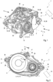
- Fig. 1 to 5 show a preferred embodiment of a drive device marked in its entirety with the reference number 1 for a bicycle which is not illustrated, for example an E-bike or a Pedelec.
- the shown drive device 1 has a multi-part housing 3 practically produced from a light metal or plastic or a plastic composite material having a first monolithic substantially tub-shaped housing part 4 and a second monolithic substantially tub-shaped housing part 5 which, here, are fixed to one another at their open housing sides by way of an encircling flange screw connection 38. Furthermore, the drive device 1 has a drive unit 2 substantially accommodated completely in the interior of the housing 3 which drives the bicycle, when it is embodied as E-bike, without additional pedalling support, or which, when it is embodied as Pedelec, supports as pedalling support a user of the bicycle while driving the bicycle.
- the drive unit 2 comprises a drive shaft designated 10, which penetrates a first opening 6 of the first housing part 4 and a second opening 7 of the second housing part 5, which in the axial direction 8 of an axis of rotation 9 of the drive shaft 10, here drawn in with dash-dotted line, are aligned with one another, in each case forming a shaft axial end 11, 12 protruding over the first housing part 4 or over the second housing part 5.
- the latter are equipped for arranging pedals of the drive unit 2 which are not illustrated here, so that the user can comfortably pedal and introduce at the drive shafts 10 a pedal torque for driving the bicycle.
- the drive unit 2 of the drive device 1 additionally has an output shaft 13, in particular a hollow output shaft which, here, penetrates the first opening 6 forming an axial protrusion 14 enclosing with respect to the axis of rotation 9 the drive shaft 10 coaxially.
- an attachment part 15 referred to as spider in practice is fixed to the axial protrusion 14 of the output shaft 13.
- a chain ring which is not shown here for a drive chain of the drive device 1 which is likewise not illustrated can be mounted on the attachment part 15.
- the drive unit 2 has an electric drive motor which is not shown which is fed by a battery of the bicycle, which drive motor provides a motor torque and a transmission which is likewise not shown.
- the bicycle when the bicycle is embodied as E-bike, is equipped in order to convert the motor torque of the drive motor into a drive torque providing the same to the output shaft 13.
- the transmission is equipped to convert the pedal torque provided by the user and the motor torque of the drive motor, which is provided by the drive motor for example according to a specified support stage at different levels, into a drive torque and provide the same at the output shaft 13.
- the housing 3 on the first housing part 4 comprises first attachment features 16 for fixing the drive device 1 to a frame 19 of the bicycle which is indicated only symbolically and on the second housing part 5 second attachment features 17 distinct with respect to the first attachment features 16 for fixing the drive device 1 to the frame 19.
- the first attachment features 16 are exemplarily realised by threaded blind hole bores and/or threaded through-bores 28 extending into the first housing part 4. Because of this, the first attachment features 16 do not protrude over the housing 3 or the first housing part 4 but are completely integrated in the first housing part 3.
- the second attachment features 17, in contrast with the first attachment features 16, are in multiple parts.
- insert sleeves 31 can be produced for example from an aluminium material and, in the inserted state, are each completely inserted or pressed into such a through-bore 29 that a respective insert sleeve 31 does not protrude over the second housing part 5 but ends flush with its housing part surface 40.
- the insert sleeves 31, here have a hollow circular ring-cylindrical main body 39 each, which has two opposite main body axial ends 34a, 34b, wherein on the one main body axial end 34a facing away with respect to the second housing part 5 a support collar 36 protruding over an outer lateral surface 35 of the main body 39 and encircling the main body 39 in portions is provided.
- the support collars 36 of the insert sleeves 31 are configured so that a respective insert sleeve 31, in the state inserted into a through-bore 29, can touchingly support itself on the second housing part 5 by way of the support collar 36. In the inserted state, the support collars 36 are completely recessed into a through-bore 29.
- the first and second attachment features 16, 17 do not protrude over the housing 3 or the first and second housing part 4, 5 but are quasi-countersunk or integrated. Because of this, the proposed drive device 1 or the housing 3 can be a relatively compact structure in the axial direction 8 of the axis of rotation 9.
- the drive device 1 furthermore, comprises a circuit board arranged in the housing 3 equipped with electronic components that are not visible, which is in particular a so-called PCB (printed circuit board).
- the same has a connection interface 20 penetrating the first housing part 4, which has at least one plug connector 21 protruding over the first housing part 4 for connecting a mating plug connector 26 of a sensor line 27 of the bicycle.
- the plug connector 21 is embodied angled and forms a 90° angular plug connector.
- the plug connector 21 comprises a connector base 22 that is more or less parallel with respect to the axis of rotation 9 and directly acts on the connection interface 20, and a connector extension 23 following thereon. With respect to the connector base 22, the connector extension 23 is angled so that the connector extension 23 and the connector base 22 between them or the connector extension 23 and the axis of rotation 9 between them define an angle which exemplarily amounts to 90°.
- the angular plug connector 21 comprises contact pins 24 and the mating plug connector 26 of the sensor line 27, complementary contact jacks 25, into which the contact pins 24 of the plug connector 21 can be plugged.
- the said sensor line 27 can be run along the frame 19 of the bicycle and routed more or less at a right angle to the axis of rotation 9 towards the plug connector 21 of the drive device 1 and mounted thereon.
- the mating plug connector 26 of the sensor line 27 can be embodied as a cost-effective flat mating plug connector, since the plug connector 21 is already angled. Because of the angular plug connector 21 the drive device is a relatively compact construction in the axial direction 8 of the axis of rotation 9.
- the first housing part 4 has third attachment features 18 for fixing a chain guide of the drive device 1 which is not illustrated for guiding a chain of the drive device 1 engaging with the attachment part 15, see Fig. 3 .
- These are realised by threaded blind hole bores and/or threaded through-bores 37 extending into the first housing part 4.
Landscapes
- Engineering & Computer Science (AREA)
- Mechanical Engineering (AREA)
- Chemical & Material Sciences (AREA)
- Combustion & Propulsion (AREA)
- Transportation (AREA)
- Transmission Devices (AREA)
Abstract
Description
- The invention relates to a drive device for a bicycle, in particular an E-bike or a Pedelec, according to the subject of
Claim 1. The invention relates in particular to a centre drive or bottom bracket drive comprising a drive device and further in particular to a bicycle, in particular an E-bike or a Pedelec, comprising such a centre drive or bottom bracket drive. - Known drive devices provide via an output shaft a torque for driving the bicycle. They are relatively large constructions which, in particular for aesthetic reasons, is undesirable. Furthermore, large drive devices are generally relatively heavy which, with regard to performance that is important in bicycles (for example sportive driving characteristics) is likewise undesirable.
- The object of the invention therefore lies in providing an improved or at least another embodiment of a drive device. In particular, a comparatively compact drive device, an advantageous drive for a bicycle and an advantageous bicycle are to be stated.
- With the present invention, this object is achieved in particular through the subjects of the independent claims. Advantageous embodiments are subject of the dependent claims and of the description.
- The invention has recognised in particular that a relatively compact drive device can be provided in that a plug connector previously projecting away, finger-like, from a housing of the drive device is replaced with an angular plug connector. The invention, furthermore, has recognised that by a practical configuration of attachment features of the drive device utilised for fixing the drive device to a frame of the bicycle a comparatively compact drive device can be realised.
- Accordingly, a drive device for a bicycle, in particular an E-bike or a Pedelec, is provided, which comprises a multi-part housing accommodating a drive unit of the drive device, said housing comprises a first monolithic housing part having a first opening and a second monolithic housing part having a second opening which is fixed to the first housing part for example by a screw connection, wherein the second opening is aligned in the axial direction of an axis of rotation of a drive shaft of the drive unit with the first opening. Furthermore, it is provided that the drive shaft penetrates the first opening and the second opening forming shaft axial ends protruding over the first housing part and second housing part for arranging pedals of the drive unit. Furthermore, the drive unit comprises an output shaft which penetrates the first opening forming an axial protrusion protruding over the first housing part and enclosing the drive shaft coaxially with respect to the axis of rotation for arranging an attachment part referred to as spider in practice, on which for example a chain ring for a drive chain can be mounted. The first housing part has first attachment features for fixing the drive device to a frame of the bicycle. Furthermore, the second housing part has second attachment features for fixing the drive device to the frame of the bicycle. It is substantial that the drive device comprises a circuit board arranged in the housing and equipped with electronic components, in particular a so-called PCB (printed circuit board), which has a connection interface penetrating the first housing part, which has at least one angular plug connector protruding over the first housing part for connecting a mating plug connector of a sensor line of the bicycle.
- Because of the angular plug connector, the proposed drive device is a relatively compact construction in particular in the axial direction of the axis of rotation. Apart from this, the drive device makes possible using a cost-effective sensor line with a mating plug connector of straight configuration, for example a flat mating plug connector having a diameter of less than 10 mm, since the angulation is realised by the plug connector.
- The sensor line can be communicatingly connected to a sensor arranged on the bicycle, for example a speed sensor. For this purpose, the sensor line can be installed on or within a frame of the bicycle.
- It is practical when the angular plug connector comprises a connector base parallel with respect to the axis of rotation engaging with the connection interface and a connector extension following thereon. The connector extension can be embodied angled with respect to the connector base so that between the connector extension and the axis of rotation an angle is defined. The said angle can amount to for example substantially 90° or 90°. Thus, when the sensor line is installed on or within a frame of the bicycle and routed to the drive device more or less at right angles to the axis of rotation, not only a relatively compact drive device is realised but a favourable mountability of the mating plug connector of the sensor line on the angular plug connector can be accomplished as well. It is practical when the angular plug connector forms a 90° angular plug connector.
- It is practical, further, when the angular plug connector comprises contact pins and the mating plug connector of the sensor line contact jacks into which the contact pins of the mating plug connector can be plugged. Alternatively it is also conceivable that the mating plug connector of the sensor line comprises contact pins and the angled plug connector contact jacks into which the contact pins of the mating plug connector can be plugged. By way of this, a preferred configuration for the plug and mating plug connector is stated.
- It is practical, further, when the first attachment features are realised by threaded blind hole bores and/or threaded through-bores extending into the first housing part. The first attachment features thus do not protrude over the housing or the first housing part but are quasi-recessed or integrated in the first housing part. Because of this, the proposed drive device can be a relatively compact construction in the axial direction of the axis of rotation.
- It is practical when the second attachment features are realised by threadless through-bores which extend completely through shoulder projections of the second housing part, and insert sleeves with internal thread, which are each inserted into a through-bore. Because of this, the second attachment features do not protrude over the housing or the second housing part but are quasi-recessed or integrated in the shoulder projections of the second housing part. Because of this, the proposed drive device can be an even more compact construction in the axial direction of the axis of rotation than before.
- The insert sleeves can each have a hollow circular ring-cylindrical main body. On a main body axial end of such a main body, a support collar protruding over an outer lateral surface of the main body encircling the main body in portions can be provided, by way of which the insert sleeve, when inserted into a through-bore arranged on the second housing part, touchingly supports itself on the second housing part.
- In order to be able to produce the said insert sleeves to be light in weight and at the same time in large quantities it can be provided that the insert sleeves are produced from an aluminium material.
- By way of the first and second attachment features the proposed drive device can be attached to a frame of the bicycle so that even relatively large torque loads of for example greater than 45 Nm applied via each pedal can be transferred via the housing of the drive device to the frame.
- It is practical, further, when the first housing part comprises third attachment features for fixing a chain guide of the drive device for guiding a chain of the drive device engaging with the attachment part, wherein the first attachment features are realised by threaded bores extending into the first housing part, in particular further threaded blind hole bores and/or threaded through-bores. By way of the third attachment features the chain guide can then be fixed to the housing.
- According to a further basic idea of the invention, a centre drive or a bottom bracket drive for a bicycle is provided, which is arranged on the frame of a bicycle, in particular an E-bike or a Pedelec, in the region of the pedals of the bicycle and comprises a drive device according to the preceding description. Because of this, a centre drive or bottom bracket drive is provided, which is relatively compact because of the advantageous drive device that can be provided.
- The drive device, when it is integrated in the centre drive or the bottom bracket drive, can be employed as pedalling support for the bicycle or as drive for the bicycle.
- According to a further basic idea of the invention, a bicycle, in particular an E-bike or a Pedelec, is provided which comprises a centre drive or bottom bracket drive according to the preceding description. Because of this, a bicycle having a centre drive or bottom bracket drive is provided which, because of the drive device employed, is a relatively compact construction.
- In summary it should be noted: the present invention preferentially relates to a drive device for a bicycle which comprises a multi-part housing accommodating a drive unit of the drive device having a first housing part and a second housing part fixed thereon. It is substantial for the invention that the drive device comprises a circuit board equipped with electronic components arranged in the housing, in particular a so-called PCB (printed circuit board), which has a connection interface penetrating the first housing part which has at least one angular plug connector protruding over the first housing part for connecting a mating plug connector of a sensor line. The invention relates in particular to a centre drive or a bottom bracket drive having such a drive device and further in particular to a bicycle comprising such a centre drive or bottom bracket drive.
- Further important features and advantages of the invention are obtained from the subclaims, from the drawings and from the associated figure description by way of the drawings.
- It is to be understood that the features mentioned above and still to be explained in the following cannot only be used in the respective combination stated, but also in other combinations or by themselves without leaving the scope of the present invention.
- A preferred embodiment of the invention is shown in the drawings and explained in more detail in the following description, wherein same reference numbers relate to same or similar or functionally same components.
- It shows, in each case schematically
- Fig. 1
- a perspective view of a preferred embodiment of a drive device for a bicycle,
- Fig. 2
- the drive device from
Fig. 1 in viewing direction of an arrow II drawn in there, - Fig. 3
- the drive device from
Fig. 1 in viewing direction of an arrow III drawn in there, however without attachment part, - Fig. 4
- an extract of the drive device from
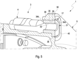
Fig. 3 looking in the direction of an arrow IV of a connection interface of the drive device drawn in there and finally - Fig. 5
- a perspective sectional view of the drive device from
Fig. 2 along a section line A-A drawn in there. -
Fig. 1 to 5 show a preferred embodiment of a drive device marked in its entirety with thereference number 1 for a bicycle which is not illustrated, for example an E-bike or a Pedelec. - The shown
drive device 1 has amulti-part housing 3 practically produced from a light metal or plastic or a plastic composite material having a first monolithic substantially tub-shaped housing part 4 and a second monolithic substantially tub-shaped housing part 5 which, here, are fixed to one another at their open housing sides by way of an encirclingflange screw connection 38. Furthermore, thedrive device 1 has a drive unit 2 substantially accommodated completely in the interior of thehousing 3 which drives the bicycle, when it is embodied as E-bike, without additional pedalling support, or which, when it is embodied as Pedelec, supports as pedalling support a user of the bicycle while driving the bicycle. - The drive unit 2 comprises a drive shaft designated 10, which penetrates a
first opening 6 of thefirst housing part 4 and asecond opening 7 of thesecond housing part 5, which in theaxial direction 8 of an axis ofrotation 9 of the drive shaft 10, here drawn in with dash-dotted line, are aligned with one another, in each case forming a shaft axial end 11, 12 protruding over thefirst housing part 4 or over thesecond housing part 5. The latter are equipped for arranging pedals of the drive unit 2 which are not illustrated here, so that the user can comfortably pedal and introduce at the drive shafts 10 a pedal torque for driving the bicycle. The drive unit 2 of thedrive device 1 additionally has an output shaft 13, in particular a hollow output shaft which, here, penetrates thefirst opening 6 forming an axial protrusion 14 enclosing with respect to the axis ofrotation 9 the drive shaft 10 coaxially. InFig. 1 it is evident that anattachment part 15 referred to as spider in practice is fixed to the axial protrusion 14 of the output shaft 13. For example, a chain ring which is not shown here for a drive chain of thedrive device 1 which is likewise not illustrated can be mounted on theattachment part 15. Furthermore, the drive unit 2 has an electric drive motor which is not shown which is fed by a battery of the bicycle, which drive motor provides a motor torque and a transmission which is likewise not shown. The latter, when the bicycle is embodied as E-bike, is equipped in order to convert the motor torque of the drive motor into a drive torque providing the same to the output shaft 13. When, alternatively, the bicycle is embodied as Pedelec, the transmission is equipped to convert the pedal torque provided by the user and the motor torque of the drive motor, which is provided by the drive motor for example according to a specified support stage at different levels, into a drive torque and provide the same at the output shaft 13. - In the figures it is evident, furthermore, that the
housing 3 on thefirst housing part 4 comprises first attachment features 16 for fixing thedrive device 1 to aframe 19 of the bicycle which is indicated only symbolically and on thesecond housing part 5 second attachment features 17 distinct with respect to the first attachment features 16 for fixing thedrive device 1 to theframe 19. The first attachment features 16 are exemplarily realised by threaded blind hole bores and/or threaded through-bores 28 extending into thefirst housing part 4. Because of this, the first attachment features 16 do not protrude over thehousing 3 or thefirst housing part 4 but are completely integrated in thefirst housing part 3. The second attachment features 17, in contrast with the first attachment features 16, are in multiple parts. They have thread-free through-bores 29 which extend completely throughshoulder projections 30 of thesecond housing part 4 protruding over thesecond housing part 5 transversely to the axis ofrotation 9 of thesecond housing part 5, andseparate insert sleeves 31 withinternal thread 32. Theinsert sleeves 31 can be produced for example from an aluminium material and, in the inserted state, are each completely inserted or pressed into such a through-bore 29 that arespective insert sleeve 31 does not protrude over thesecond housing part 5 but ends flush with itshousing part surface 40. InFig. 5 it is noticeable that theinsert sleeves 31, here, have a hollow circular ring-cylindricalmain body 39 each, which has two opposite main body axial ends 34a, 34b, wherein on the one main bodyaxial end 34a facing away with respect to the second housing part 5 asupport collar 36 protruding over an outerlateral surface 35 of themain body 39 and encircling themain body 39 in portions is provided. Thesupport collars 36 of theinsert sleeves 31 are configured so that arespective insert sleeve 31, in the state inserted into a through-bore 29, can touchingly support itself on thesecond housing part 5 by way of thesupport collar 36. In the inserted state, thesupport collars 36 are completely recessed into a through-bore 29. Because of these measures, the first and second attachment features 16, 17 do not protrude over thehousing 3 or the first andsecond housing part drive device 1 or thehousing 3 can be a relatively compact structure in theaxial direction 8 of the axis ofrotation 9. - The
drive device 1, furthermore, comprises a circuit board arranged in thehousing 3 equipped with electronic components that are not visible, which is in particular a so-called PCB (printed circuit board). The same has aconnection interface 20 penetrating thefirst housing part 4, which has at least oneplug connector 21 protruding over thefirst housing part 4 for connecting a mating plug connector 26 of asensor line 27 of the bicycle. InFig. 3 and 4 it is noticeable that theplug connector 21 is embodied angled and forms a 90° angular plug connector. Theplug connector 21 comprises aconnector base 22 that is more or less parallel with respect to the axis ofrotation 9 and directly acts on theconnection interface 20, and aconnector extension 23 following thereon. With respect to theconnector base 22, theconnector extension 23 is angled so that theconnector extension 23 and theconnector base 22 between them or theconnector extension 23 and the axis ofrotation 9 between them define an angle which exemplarily amounts to 90°. - According to the illustrated embodiment in
Fig. 3 and 4 it is provided that theangular plug connector 21 comprises contact pins 24 and the mating plug connector 26 of thesensor line 27, complementary contact jacks 25, into which the contact pins 24 of theplug connector 21 can be plugged. By way of theangular plug connector 21, the saidsensor line 27 can be run along theframe 19 of the bicycle and routed more or less at a right angle to the axis ofrotation 9 towards theplug connector 21 of thedrive device 1 and mounted thereon. The mating plug connector 26 of thesensor line 27 can be embodied as a cost-effective flat mating plug connector, since theplug connector 21 is already angled. Because of theangular plug connector 21 the drive device is a relatively compact construction in theaxial direction 8 of the axis ofrotation 9. It should be mentioned, furthermore, that thefirst housing part 4 has third attachment features 18 for fixing a chain guide of thedrive device 1 which is not illustrated for guiding a chain of thedrive device 1 engaging with theattachment part 15, seeFig. 3 . These are realised by threaded blind hole bores and/or threaded through-bores 37 extending into thefirst housing part 4.
Claims (10)
- A drive device (1) for a bicycle, in particular an E-bike or a Pedelec, comprising- a multi-part housing (3) accommodating a drive unit (2) of the drive device (1), the housing (3) comprises a first monolithic housing part (4) having a first opening (6) and a second monolithic housing part (5) fixed to the first housing part (4) having a second opening (7) aligned in the axial direction (8) of an axis of rotation (9) of a drive shaft (10) of the drive unit (2) with the first opening (6),- wherein the drive shaft (10) penetrates the first opening (6) and the second opening (7) forming shaft axial ends (11, 12) protruding over the first housing part (4) and second housing part (5) for arranging pedals of the drive unit (2),- wherein the drive unit (2) comprises an output shaft (13), which penetrates the first opening (6) forming an axial protrusion (14) protruding over the first housing part (4) and enclosing the drive shaft (10) coaxially with respect to the axis of rotation (9) for arranging an attachment part (15),- wherein the first housing part (4) comprises first attachment features (16) for fixing the drive device (1) to a frame (19) of the bicycle,- wherein the second housing part (5) comprises second attachment features (17) for fixing the drive device (1) to the frame (19) of the bicycle,- wherein the drive device (1) comprises a circuit board arranged in the housing (3) equipped with electronic components, which has a connection interface (20) penetrating the first housing part (4), which has at least one angular plug connector (21) protruding over the first housing part (4) for connecting a mating plug connector (26) of a sensor line (27).
- The drive device (1) according to Claim 1,
characterised in that- the angular plug connector (21) has a connector base (22) that is parallel with respect to the axis of rotation (9) and engaging with the connection interface (20) and a connector extension (23) following thereon,- wherein the connector extension (23) with respect to the connector base (22) is angled so that between the connector extension (23) and the axis of rotation (9) an angle is defined. - The drive device (1) according to Claim 2,
characterised in that- the said angle substantially amounts to 90° or is 90°. - The drive device (1) according to any one of the preceding claims, characterised in that- the angular plug connector (21) forms a 90° angular plug connector.
- The drive device (1) according to any one of the preceding claims,
characterised in that- the angular plug connector (21) comprises contact pins (24) and the mating plug connector (26) of the sensor line (27) contact jacks, into which the contact pins (24) of the plug connector (21) can be plugged, or- the mating plug connector (26) of the sensor line (27) comprises contact pins (24) and the angular plug connector (21) contact jacks, into which the contact pins (24) of the mating plug connector (26) can be plugged. - The drive device (1) according to any one of the preceding claims,
characterised in that- the first attachment features (16) are realised by threaded blind hole bores and/or threaded through-bores (28) extending into the first housing part (4). - The drive device (1) according to any one of the preceding claims,
characterised in that- the second attachment features (17) are realised by thread-free through-bores (29), which extend completely through shoulder projections (30) of the second housing part (5), and insert sleeves (31) with internal thread (32), which are each inserted into a through-bore (29). - The drive device (1) according to any one of the preceding claims,
characterised in that- the first housing part (4) has third attachment features (18) for fixing a chain guide of the drive device (1) for guiding a chain of the drive device (1) engaging with the attachment part (15),- wherein the third attachment features (18) are realised by threaded blind hole bores and/or threaded through-bores (37) extending into the first housing part (4). - A centre drive or a bottom bracket drive comprising a drive device (1) arranged in the frame (19) of a bicycle, in particular an E-bike or a Pedelec, in the region of the pedals of the bicycle according to any one of the Claims 1 to 8.
- A bicycle, in particular an E-bike or a Pedelec, comprising a centre drive or bottom bracket drive according to Claim 9.
Priority Applications (2)
| Application Number | Priority Date | Filing Date | Title |
|---|---|---|---|
| EP23169463.9A EP4454986B1 (en) | 2023-04-24 | 2023-04-24 | Drive device, centre drive or bottom bracket drive comprising such a drive device and bicycle |
| ES23169463T ES3052435T3 (en) | 2023-04-24 | 2023-04-24 | Drive device, centre drive or bottom bracket drive comprising such a drive device and bicycle |
Applications Claiming Priority (1)
| Application Number | Priority Date | Filing Date | Title |
|---|---|---|---|
| EP23169463.9A EP4454986B1 (en) | 2023-04-24 | 2023-04-24 | Drive device, centre drive or bottom bracket drive comprising such a drive device and bicycle |
Publications (2)
| Publication Number | Publication Date |
|---|---|
| EP4454986A1 true EP4454986A1 (en) | 2024-10-30 |
| EP4454986B1 EP4454986B1 (en) | 2025-08-27 |
Family
ID=86185316
Family Applications (1)
| Application Number | Title | Priority Date | Filing Date |
|---|---|---|---|
| EP23169463.9A Active EP4454986B1 (en) | 2023-04-24 | 2023-04-24 | Drive device, centre drive or bottom bracket drive comprising such a drive device and bicycle |
Country Status (2)
| Country | Link |
|---|---|
| EP (1) | EP4454986B1 (en) |
| ES (1) | ES3052435T3 (en) |
Citations (7)
| Publication number | Priority date | Publication date | Assignee | Title |
|---|---|---|---|---|
| CN202574548U (en) * | 2012-05-03 | 2012-12-05 | 陈戈平 | Line connecting structure of boosting bicycle |
| US9834278B2 (en) * | 2016-04-28 | 2017-12-05 | Yamaha Hatsudoki Kabushiki Kaisha | Drive unit and electric-motor-assisted bicycle |
| US10036465B2 (en) * | 2015-07-17 | 2018-07-31 | Shimano Inc. | Bicycle component |
| DE102018120095A1 (en) * | 2017-08-25 | 2019-02-28 | Shimano Inc. | BICYCLE DRIVE UNIT |
| EP3647175A1 (en) * | 2018-10-29 | 2020-05-06 | Miranda & Irmão Lda. | Drive system for an electric bicycle |
| CN211943642U (en) * | 2019-09-27 | 2020-11-17 | 无锡川克智能电机有限公司 | Power assembly of electric power-assisted bicycle |
| EP4089851A1 (en) * | 2021-05-12 | 2022-11-16 | Werner Wirth GmbH | Connector system for an electric bicycle |
-
2023
- 2023-04-24 ES ES23169463T patent/ES3052435T3/en active Active
- 2023-04-24 EP EP23169463.9A patent/EP4454986B1/en active Active
Patent Citations (7)
| Publication number | Priority date | Publication date | Assignee | Title |
|---|---|---|---|---|
| CN202574548U (en) * | 2012-05-03 | 2012-12-05 | 陈戈平 | Line connecting structure of boosting bicycle |
| US10036465B2 (en) * | 2015-07-17 | 2018-07-31 | Shimano Inc. | Bicycle component |
| US9834278B2 (en) * | 2016-04-28 | 2017-12-05 | Yamaha Hatsudoki Kabushiki Kaisha | Drive unit and electric-motor-assisted bicycle |
| DE102018120095A1 (en) * | 2017-08-25 | 2019-02-28 | Shimano Inc. | BICYCLE DRIVE UNIT |
| EP3647175A1 (en) * | 2018-10-29 | 2020-05-06 | Miranda & Irmão Lda. | Drive system for an electric bicycle |
| CN211943642U (en) * | 2019-09-27 | 2020-11-17 | 无锡川克智能电机有限公司 | Power assembly of electric power-assisted bicycle |
| EP4089851A1 (en) * | 2021-05-12 | 2022-11-16 | Werner Wirth GmbH | Connector system for an electric bicycle |
Also Published As
| Publication number | Publication date |
|---|---|
| EP4454986B1 (en) | 2025-08-27 |
| ES3052435T3 (en) | 2026-01-07 |
Similar Documents
| Publication | Publication Date | Title |
|---|---|---|
| US12539937B2 (en) | Motor unit with improved heat dissipation capability for use in electric bicycles | |
| DE102018212842B4 (en) | Bicycle component and mounting structure for a bicycle component | |
| DE102008020144B4 (en) | power tool | |
| US10260568B2 (en) | Connecting device for chainring of bicycle | |
| DE112019002605T5 (en) | MOTOR UNIT AND ELECTRIC BIKE | |
| TWI901710B (en) | Bicycle derailleur and link pin for bicycle derailleur | |
| US11565772B2 (en) | Bicycle derailleur, bicycle gear structure, bicycle motor unit, and front derailleur | |
| JP2023519268A (en) | drive unit | |
| CN104290855A (en) | Multi-sprocket device for bicycle transmission mechanism | |
| EP1433698B1 (en) | Gear position detection system for transmission | |
| CN111469969A (en) | Bicycle component | |
| US12151783B2 (en) | Chain guide of bicycle derailleur | |
| DE202018006492U1 (en) | Bicycle component | |
| KR20200033860A (en) | Oil pump drive | |
| DE102022104398A1 (en) | MOTOR UNIT AND ELECTRIC BICYCLE | |
| DE102006057732A1 (en) | Throttle position sensor | |
| EP4454986B1 (en) | Drive device, centre drive or bottom bracket drive comprising such a drive device and bicycle | |
| CN111391960A (en) | Chain wheel direct-drive type middle shaft transmission mechanism | |
| EP4126649B1 (en) | Drive unit | |
| US20050206349A1 (en) | Hybrid transmission motor module with integral wire connections | |
| DE102022102426B4 (en) | Display device for an electric motor-assisted bicycle and electric motor-assisted bicycle | |
| US4922599A (en) | Method of converting a four speed manual transmission to a five speed transmission | |
| KR20080040600A (en) | Balancing shaft unit | |
| CN111391961A (en) | Middle shaft transmission device of electric bicycle | |
| JP4214762B2 (en) | Assembling the torque transmitter |
Legal Events
| Date | Code | Title | Description |
|---|---|---|---|
| PUAI | Public reference made under article 153(3) epc to a published international application that has entered the european phase |
Free format text: ORIGINAL CODE: 0009012 |
|
| STAA | Information on the status of an ep patent application or granted ep patent |
Free format text: STATUS: THE APPLICATION HAS BEEN PUBLISHED |
|
| AK | Designated contracting states |
Kind code of ref document: A1 Designated state(s): AL AT BE BG CH CY CZ DE DK EE ES FI FR GB GR HR HU IE IS IT LI LT LU LV MC ME MK MT NL NO PL PT RO RS SE SI SK SM TR |
|
| STAA | Information on the status of an ep patent application or granted ep patent |
Free format text: STATUS: REQUEST FOR EXAMINATION WAS MADE |
|
| GRAP | Despatch of communication of intention to grant a patent |
Free format text: ORIGINAL CODE: EPIDOSNIGR1 |
|
| STAA | Information on the status of an ep patent application or granted ep patent |
Free format text: STATUS: GRANT OF PATENT IS INTENDED |
|
| 17P | Request for examination filed |
Effective date: 20250317 |
|
| RIC1 | Information provided on ipc code assigned before grant |
Ipc: B62J 45/40 20200101ALN20250401BHEP Ipc: B62M 9/00 20060101ALN20250401BHEP Ipc: B62K 19/34 20060101ALI20250401BHEP Ipc: B62J 11/19 20200101ALI20250401BHEP Ipc: B62M 6/50 20100101ALI20250401BHEP Ipc: B62M 6/55 20100101AFI20250401BHEP |
|
| INTG | Intention to grant announced |
Effective date: 20250414 |
|
| GRAS | Grant fee paid |
Free format text: ORIGINAL CODE: EPIDOSNIGR3 |
|
| GRAA | (expected) grant |
Free format text: ORIGINAL CODE: 0009210 |
|
| STAA | Information on the status of an ep patent application or granted ep patent |
Free format text: STATUS: THE PATENT HAS BEEN GRANTED |
|
| AK | Designated contracting states |
Kind code of ref document: B1 Designated state(s): AL AT BE BG CH CY CZ DE DK EE ES FI FR GB GR HR HU IE IS IT LI LT LU LV MC ME MK MT NL NO PL PT RO RS SE SI SK SM TR |
|
| REG | Reference to a national code |
Ref country code: CH Ref legal event code: EP |
|
| REG | Reference to a national code |
Ref country code: DE Ref legal event code: R096 Ref document number: 602023006005 Country of ref document: DE |
|
| REG | Reference to a national code |
Ref country code: IE Ref legal event code: FG4D |
|
| REG | Reference to a national code |
Ref country code: NL Ref legal event code: MP Effective date: 20250827 |
|
| REG | Reference to a national code |
Ref country code: ES Ref legal event code: FG2A Ref document number: 3052435 Country of ref document: ES Kind code of ref document: T3 Effective date: 20260107 |
|
| PG25 | Lapsed in a contracting state [announced via postgrant information from national office to epo] |
Ref country code: IS Free format text: LAPSE BECAUSE OF FAILURE TO SUBMIT A TRANSLATION OF THE DESCRIPTION OR TO PAY THE FEE WITHIN THE PRESCRIBED TIME-LIMIT Effective date: 20251227 |
|
| PG25 | Lapsed in a contracting state [announced via postgrant information from national office to epo] |
Ref country code: NO Free format text: LAPSE BECAUSE OF FAILURE TO SUBMIT A TRANSLATION OF THE DESCRIPTION OR TO PAY THE FEE WITHIN THE PRESCRIBED TIME-LIMIT Effective date: 20251127 |
|
| REG | Reference to a national code |
Ref country code: LT Ref legal event code: MG9D |
|
| PG25 | Lapsed in a contracting state [announced via postgrant information from national office to epo] |
Ref country code: PT Free format text: LAPSE BECAUSE OF FAILURE TO SUBMIT A TRANSLATION OF THE DESCRIPTION OR TO PAY THE FEE WITHIN THE PRESCRIBED TIME-LIMIT Effective date: 20251229 |
|
| PG25 | Lapsed in a contracting state [announced via postgrant information from national office to epo] |
Ref country code: FI Free format text: LAPSE BECAUSE OF FAILURE TO SUBMIT A TRANSLATION OF THE DESCRIPTION OR TO PAY THE FEE WITHIN THE PRESCRIBED TIME-LIMIT Effective date: 20250827 |
|
| PG25 | Lapsed in a contracting state [announced via postgrant information from national office to epo] |
Ref country code: HR Free format text: LAPSE BECAUSE OF FAILURE TO SUBMIT A TRANSLATION OF THE DESCRIPTION OR TO PAY THE FEE WITHIN THE PRESCRIBED TIME-LIMIT Effective date: 20250827 Ref country code: NL Free format text: LAPSE BECAUSE OF FAILURE TO SUBMIT A TRANSLATION OF THE DESCRIPTION OR TO PAY THE FEE WITHIN THE PRESCRIBED TIME-LIMIT Effective date: 20250827 |
|
| PG25 | Lapsed in a contracting state [announced via postgrant information from national office to epo] |
Ref country code: GR Free format text: LAPSE BECAUSE OF FAILURE TO SUBMIT A TRANSLATION OF THE DESCRIPTION OR TO PAY THE FEE WITHIN THE PRESCRIBED TIME-LIMIT Effective date: 20251128 |
|
| PG25 | Lapsed in a contracting state [announced via postgrant information from national office to epo] |
Ref country code: SE Free format text: LAPSE BECAUSE OF FAILURE TO SUBMIT A TRANSLATION OF THE DESCRIPTION OR TO PAY THE FEE WITHIN THE PRESCRIBED TIME-LIMIT Effective date: 20250827 |
|
| PG25 | Lapsed in a contracting state [announced via postgrant information from national office to epo] |
Ref country code: LV Free format text: LAPSE BECAUSE OF FAILURE TO SUBMIT A TRANSLATION OF THE DESCRIPTION OR TO PAY THE FEE WITHIN THE PRESCRIBED TIME-LIMIT Effective date: 20250827 |
|
| PG25 | Lapsed in a contracting state [announced via postgrant information from national office to epo] |
Ref country code: BG Free format text: LAPSE BECAUSE OF FAILURE TO SUBMIT A TRANSLATION OF THE DESCRIPTION OR TO PAY THE FEE WITHIN THE PRESCRIBED TIME-LIMIT Effective date: 20250827 Ref country code: PL Free format text: LAPSE BECAUSE OF FAILURE TO SUBMIT A TRANSLATION OF THE DESCRIPTION OR TO PAY THE FEE WITHIN THE PRESCRIBED TIME-LIMIT Effective date: 20250827 |
|
| PG25 | Lapsed in a contracting state [announced via postgrant information from national office to epo] |
Ref country code: RS Free format text: LAPSE BECAUSE OF FAILURE TO SUBMIT A TRANSLATION OF THE DESCRIPTION OR TO PAY THE FEE WITHIN THE PRESCRIBED TIME-LIMIT Effective date: 20251127 |
|
| REG | Reference to a national code |
Ref country code: AT Ref legal event code: MK05 Ref document number: 1829720 Country of ref document: AT Kind code of ref document: T Effective date: 20250827 |
|
| PG25 | Lapsed in a contracting state [announced via postgrant information from national office to epo] |
Ref country code: SM Free format text: LAPSE BECAUSE OF FAILURE TO SUBMIT A TRANSLATION OF THE DESCRIPTION OR TO PAY THE FEE WITHIN THE PRESCRIBED TIME-LIMIT Effective date: 20250827 |
|
| P01 | Opt-out of the competence of the unified patent court (upc) registered |
Free format text: CASE NUMBER: UPC_APP_0008694_4454986/2026 Effective date: 20260304 |
|
| PG25 | Lapsed in a contracting state [announced via postgrant information from national office to epo] |
Ref country code: DK Free format text: LAPSE BECAUSE OF FAILURE TO SUBMIT A TRANSLATION OF THE DESCRIPTION OR TO PAY THE FEE WITHIN THE PRESCRIBED TIME-LIMIT Effective date: 20250827 |
|
| PG25 | Lapsed in a contracting state [announced via postgrant information from national office to epo] |
Ref country code: AT Free format text: LAPSE BECAUSE OF FAILURE TO SUBMIT A TRANSLATION OF THE DESCRIPTION OR TO PAY THE FEE WITHIN THE PRESCRIBED TIME-LIMIT Effective date: 20250827 |
|
| PG25 | Lapsed in a contracting state [announced via postgrant information from national office to epo] |
Ref country code: CZ Free format text: LAPSE BECAUSE OF FAILURE TO SUBMIT A TRANSLATION OF THE DESCRIPTION OR TO PAY THE FEE WITHIN THE PRESCRIBED TIME-LIMIT Effective date: 20250827 |
|
| PG25 | Lapsed in a contracting state [announced via postgrant information from national office to epo] |
Ref country code: SK Free format text: LAPSE BECAUSE OF FAILURE TO SUBMIT A TRANSLATION OF THE DESCRIPTION OR TO PAY THE FEE WITHIN THE PRESCRIBED TIME-LIMIT Effective date: 20250827 Ref country code: EE Free format text: LAPSE BECAUSE OF FAILURE TO SUBMIT A TRANSLATION OF THE DESCRIPTION OR TO PAY THE FEE WITHIN THE PRESCRIBED TIME-LIMIT Effective date: 20250827 |
|
| REG | Reference to a national code |
Ref country code: DE Ref legal event code: R097 Ref document number: 602023006005 Country of ref document: DE |
|
| PG25 | Lapsed in a contracting state [announced via postgrant information from national office to epo] |
Ref country code: LT Free format text: LAPSE BECAUSE OF FAILURE TO SUBMIT A TRANSLATION OF THE DESCRIPTION OR TO PAY THE FEE WITHIN THE PRESCRIBED TIME-LIMIT Effective date: 20250827 |
|
| PLBE | No opposition filed within time limit |
Free format text: ORIGINAL CODE: 0009261 |
|
| STAA | Information on the status of an ep patent application or granted ep patent |
Free format text: STATUS: NO OPPOSITION FILED WITHIN TIME LIMIT |
|
| PGFP | Annual fee paid to national office [announced via postgrant information from national office to epo] |
Ref country code: ES Payment date: 20260617 Year of fee payment: 4 |
|
| REG | Reference to a national code |
Ref country code: CH Ref legal event code: L10 Free format text: ST27 STATUS EVENT CODE: U-0-0-L10-L00 (AS PROVIDED BY THE NATIONAL OFFICE) Effective date: 20260708 |
|
| PGFP | Annual fee paid to national office [announced via postgrant information from national office to epo] |
Ref country code: IT Payment date: 20260430 Year of fee payment: 4 |
|
| PGFP | Annual fee paid to national office [announced via postgrant information from national office to epo] |
Ref country code: DE Payment date: 20260422 Year of fee payment: 4 |
|
| PGFP | Annual fee paid to national office [announced via postgrant information from national office to epo] |
Ref country code: FR Payment date: 20260420 Year of fee payment: 4 |
|
| 26N | No opposition filed |
Effective date: 20260528 |