EP4454974A1 - Steering device - Google Patents
Steering device Download PDFInfo
- Publication number
- EP4454974A1 EP4454974A1 EP22908838.0A EP22908838A EP4454974A1 EP 4454974 A1 EP4454974 A1 EP 4454974A1 EP 22908838 A EP22908838 A EP 22908838A EP 4454974 A1 EP4454974 A1 EP 4454974A1
- Authority
- EP
- European Patent Office
- Prior art keywords
- movable
- steering
- vehicle
- attached
- movable member
- Prior art date
- Legal status (The legal status is an assumption and is not a legal conclusion. Google has not performed a legal analysis and makes no representation as to the accuracy of the status listed.)
- Pending
Links
- 238000006243 chemical reaction Methods 0.000 claims abstract description 59
- 230000007246 mechanism Effects 0.000 claims abstract description 18
- 238000001514 detection method Methods 0.000 claims description 11
- 239000003638 chemical reducing agent Substances 0.000 description 16
- 230000005540 biological transmission Effects 0.000 description 13
- 238000010521 absorption reaction Methods 0.000 description 4
- 239000000470 constituent Substances 0.000 description 4
- 230000035939 shock Effects 0.000 description 4
- 230000002452 interceptive effect Effects 0.000 description 3
- 230000004048 modification Effects 0.000 description 3
- 238000012986 modification Methods 0.000 description 3
- 230000002787 reinforcement Effects 0.000 description 2
- 238000005096 rolling process Methods 0.000 description 2
- 238000004378 air conditioning Methods 0.000 description 1
- 230000000694 effects Effects 0.000 description 1
- 238000005516 engineering process Methods 0.000 description 1
- 230000014509 gene expression Effects 0.000 description 1
- 239000000463 material Substances 0.000 description 1
- 238000000034 method Methods 0.000 description 1
Images


Classifications
-
- B—PERFORMING OPERATIONS; TRANSPORTING
- B62—LAND VEHICLES FOR TRAVELLING OTHERWISE THAN ON RAILS
- B62D—MOTOR VEHICLES; TRAILERS
- B62D1/00—Steering controls, i.e. means for initiating a change of direction of the vehicle
- B62D1/02—Steering controls, i.e. means for initiating a change of direction of the vehicle vehicle-mounted
- B62D1/16—Steering columns
- B62D1/18—Steering columns yieldable or adjustable, e.g. tiltable
- B62D1/181—Steering columns yieldable or adjustable, e.g. tiltable with power actuated adjustment, e.g. with position memory
-
- B—PERFORMING OPERATIONS; TRANSPORTING
- B62—LAND VEHICLES FOR TRAVELLING OTHERWISE THAN ON RAILS
- B62D—MOTOR VEHICLES; TRAILERS
- B62D1/00—Steering controls, i.e. means for initiating a change of direction of the vehicle
- B62D1/02—Steering controls, i.e. means for initiating a change of direction of the vehicle vehicle-mounted
- B62D1/16—Steering columns
- B62D1/18—Steering columns yieldable or adjustable, e.g. tiltable
- B62D1/183—Steering columns yieldable or adjustable, e.g. tiltable adjustable between in-use and out-of-use positions, e.g. to improve access
-
- B—PERFORMING OPERATIONS; TRANSPORTING
- B62—LAND VEHICLES FOR TRAVELLING OTHERWISE THAN ON RAILS
- B62D—MOTOR VEHICLES; TRAILERS
- B62D1/00—Steering controls, i.e. means for initiating a change of direction of the vehicle
- B62D1/02—Steering controls, i.e. means for initiating a change of direction of the vehicle vehicle-mounted
- B62D1/16—Steering columns
- B62D1/18—Steering columns yieldable or adjustable, e.g. tiltable
- B62D1/19—Steering columns yieldable or adjustable, e.g. tiltable incorporating energy-absorbing arrangements, e.g. by being yieldable or collapsible
- B62D1/192—Yieldable or collapsible columns
-
- B—PERFORMING OPERATIONS; TRANSPORTING
- B62—LAND VEHICLES FOR TRAVELLING OTHERWISE THAN ON RAILS
- B62D—MOTOR VEHICLES; TRAILERS
- B62D5/00—Power-assisted or power-driven steering
- B62D5/001—Mechanical components or aspects of steer-by-wire systems, not otherwise provided for in this maingroup
- B62D5/005—Mechanical components or aspects of steer-by-wire systems, not otherwise provided for in this maingroup means for generating torque on steering wheel or input member, e.g. feedback
- B62D5/006—Mechanical components or aspects of steer-by-wire systems, not otherwise provided for in this maingroup means for generating torque on steering wheel or input member, e.g. feedback power actuated
-
- B—PERFORMING OPERATIONS; TRANSPORTING
- B62—LAND VEHICLES FOR TRAVELLING OTHERWISE THAN ON RAILS
- B62D—MOTOR VEHICLES; TRAILERS
- B62D5/00—Power-assisted or power-driven steering
- B62D5/04—Power-assisted or power-driven steering electrical, e.g. using an electric servo-motor connected to, or forming part of, the steering gear
- B62D5/0409—Electric motor acting on the steering column
- B62D5/0412—Electric motor acting on the steering column the axes of motor and steering column being parallel
Definitions
- the present invention relates to steering devices holding a steering member that is steered by a driver in a vehicle etc.
- Retractable steering devices that move a steering member that is steered by a driver toward the front of a vehicle to improve driver's comfort in the vehicle during autonomous driving.
- Linkless steer-by-wire technology in which a steering shaft holding a steering member is not mechanically connected to steered wheels and information about steering is output to steer the steered wheels is sometimes used for the retractable steering devices (see, for example, Patent Document 1).
- Patent Document 1 WO2019/005736A1
- the present invention was made in view of the above problem, and it is an object of the present invention to provide a steering device that can move a steering member further toward the front of a vehicle while avoiding interference with vehicle members etc.
- a steering device that is one of the inventions is a steering device that holds a steering member in such a manner that the steering member is movable between a first position where a driver is able to steer the steering member and a second position located closer to a front of a vehicle.
- the steering device includes: a fixed member attached to a vehicle body; a movable member movably attached to the fixed member via a rail mechanism; a steering shaft attached to the movable member and rotatably holding the steering member; and a reaction force device attached to the movable member at a position non-coaxial with the steering shaft and configured to apply a reaction force to the steering shaft.
- the reaction force device is not present in a lower space extending from the steering shaft toward the front of the vehicle. This can avoid interference with vehicle members when the steering member is moved to the second position located closer to the front of the vehicle, and can increase the space in front of the driver.
- the drawings are schematic illustrations with exaggerations, omissions, or adjustments of proportions being made as appropriate in order to describe the present invention, and the shapes, positional relationships, and proportions shown in the drawings are different from actual shapes, positional relationships, and proportions.
- the X-axis, Y-axis, and Z-axis that may be shown in the drawings indicate rectangular coordinates that are set as desired in order to describe the drawings.
- the Z-axis is not necessarily an axis along the vertical direction, and the X-axis and Y-axis are not necessarily present in a horizontal plane.
- a plurality of inventions may be comprehensively described as one embodiment below. Some of the content described below is described as optional components related to the present invention.
- FIG. 1 is a perspective view of a steering device holding a steering member.
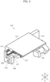
- FIG. 2 is a perspective view of a fixed member.
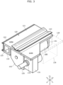
- FIG. 3 is a perspective view of a movable member and members that move with the movable member.
- FIG. 4 is a perspective view of the steering device with the fixed member, movable member, etc. omitted.
- a steering device 100 is a steering device 100 that holds a steering member 200 in such a manner that the steering member 200 is movable between a first position that is a position where a driver can steer the steering member 200 and a second position located closer to the front of the vehicle.
- the steering device 100 includes a fixed member 110, a movable member 120, a steering shaft 130, and a reaction force device 140.
- the steering device 100 includes a torque detection device 150, a reaction force transmission device 160, a steering angle sensor 170, a speed reducer 180, and a rotation amount regulation device 190.
- the fixed member 110 is a member that is fixedly attached to a reinforcement that is one of structural members of a vehicle body, etc.
- the manner in which the fixed member 110 is attached to the vehicle body is not limited, but in the present embodiment, the fixed member 110 is attached in a suspended state to a reinforcement extending in the width direction of the vehicle body.
- the sectional shape of the fixed member 110 perpendicular to the direction of movement of the movable member 120 is an L-shape rotated 90 degrees to the right.
- the fixed member 110 includes a fixed top plate portion 111 in the form of a plate and a fixed wall portion 112 extending downward from one side (Y+ side in the figure) in the width direction (Y-axis direction in the figure) of the fixed top plate portion 111.
- a first fixed rail 113 namely one of fixed rails that is a constituent member of a rail mechanism, is fixedly attached to the lower surface (surface on the Z- side in the figure) of the fixed top plate portion 111 so as to extend in the direction of movement of the movable member 120.
- a second fixed rail 114 namely one of the fixed rails that is another constituent member of the rail mechanism, is fixedly attached to the other side in the width direction (Y- side in the figure) of the fixed wall portion 112 so as to extend in the direction of movement of the movable member 120.
- the movable member 120, parts attached to the movable member 120, etc. can be slidably held with high support stiffness based on the two-rail mechanism composed of the first fixed rail 113 attached to the fixed top plate portion 111 and the second fixed rail 114 attached to the fixed wall portion 112 perpendicular to the fixed top plate portion 111.
- providing the rail mechanism on each of the perpendicular surfaces can increase torsional stiffness and allows the movable member 120 and the parts attached to the movable member 120 to slide stably.
- the rail mechanism may include a single fixed rail.
- a moving device 115 for moving the movable member 120 is attached to the lower part (Z- side in the figure) of the fixed member 110.
- the type of moving device 115 is not particularly limited, but in the present embodiment, the moving device 115 includes: a feed screw 117 that is fixedly attached to the movable member 120 via a fixed bracket 116 so as to extend in the direction of movement of the movable member 120; a movable nut 128 that meshes with the feed screw 117 and reciprocates in the direction of movement of the movable member 120 with rotation of the feed screw 117; and a rotational drive device 118 including a motor for rotating the feed screw 117.
- the movable member 120 and the parts attached to the movable member 120 can be moved smoothly.
- the movable member 120 and the parts attached to the movable member 120 can be fixed at desired positions.
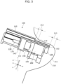
- FIG. 5 is a side view of the steering device attached to the vehicle body and a vehicle member.
- the direction of movement of the movable member 120 (X-axis in the figure) is tilted with respect to the vertical axis (V-axis in the figure) with the driver side higher than the vehicle front side.
- a vehicle member 210 such as a so-called dash panel is located on the vehicle front side of the steering device 100.
- the fixed member 110 is attached to the vehicle body in such a manner that, in a normal state (state where no collision occurs), a first clearance 212 between a fixed front end 119 of the fixed member 110 and the vehicle member 210 is larger than the amount of movement of the vehicle member 210 in case of a collision. Therefore, even if a collision occurs, the steering device 100 will not hinder the shock absorption function provided by deformation of the vehicle body.
- the movable member 120 is a member that is attached such that it can reciprocate between the first position and the second position with respect to the fixed member 110 by the rail mechanism and the moving device 115.
- the sectional shape of the movable member 120 perpendicular to the direction of movement of the movable member 120 (X-axis direction in the figure) is an L-shape rotated 90 degrees to the right.
- the movable member 120 includes a movable top plate portion 121 in the form of a plate and a movable wall portion 122 extending downward from one side (Y+ side in the figure) in the width direction (Y-axis direction in the figure) of the movable top plate portion 121.
- a first movable rail 123 namely one of movable rails that is a constituent member of a rail mechanism and that moves along the first fixed rail 113, is fixedly attached to the upper surface (surface on the Z- side in the figure) of the movable top plate portion 121 so as to extend in the direction of movement.
- a second movable rail 124 namely one of the movable rails that is another constituent member of the rail mechanism and that moves along the second fixed rail 114, is fixedly attached to one side in the width direction (Y+ side in the figure) of the movable wall portion 122 so as to extend in the direction of movement.
- the first fixed rail 113 and the first movable rail 123, and the second fixed rail 114 and the second movable rail 124, are each linearly movably coupled via two ball rows (not shown) held by a retainer.
- a two-slide structure that slides via a rolling member is placed on a surface parallel to the fixed top plate portion 111, and a two-slide structure that slides via a rolling member is also placed on a surface perpendicular to the fixed top plate portion 111. Therefore, the movable member 120, the parts attached to the movable member 120, etc. can be held with higher support stiffness so as to be slidable with respect to the fixed member 110.
- the movable member 120 integrally includes a first movable portion 121a and a second movable portion 121b.
- the first movable portion 121a and the second movable portion 121b are located next to each other in the vehicle width direction (Y-axis direction in the figure).
- the first movable portion 121a is a portion to which the first movable rail 123 is fixedly attached so as to extend in the direction of movement.
- the second movable rail 124 is also attached to the first movable portion 121a.
- the second movable portion 121b is a portion to which the steering shaft 130 is attached.
- the steering shaft 130 is attached to the second movable portion 121b via a first housing 131.
- the first movable portion 121a is longer toward the front of the vehicle (X+ side in the figure) than the second movable portion 121b. In other words, the first movable portion 121a protrudes beyond the second movable portion 121b toward the front of the vehicle. This allows the first movable portion 121a to be inserted into a space narrower than the movable member 120 in the width direction of the vehicle body, so that the stroke of movement of the movable member 120 and the parts attached to the movable member 120 with respect to the fixed member 110 can be increased.
- the movable top plate portion 121 has a cut portion 129 and has an L-shape as viewed in plan.
- the cut portion 129 is defined by the side surface on the other side in the vehicle width direction (Y- side in the figure) of a part of the first movable portion 121a that protrudes beyond the second movable portion 121b toward the front of the vehicle, and the end face on the vehicle front side of the second movable portion 122a.
- the movable member 120 and members that move with the movable member 120 are not present in the cut portion 129 and a lower space 139 that is a space where a region under the cut portion 129 and an imaginary region extended from the steering shaft 130 toward the front of the vehicle (X+ side in the figure) intersect each other.
- the vehicle member even if the vehicle member enters the cut portion 129 and the lower space 139 when the steering member 200 is moved from the first position to the second position, the vehicle member will not interfere with the movable member 120 and the members that move with the movable member 120.
- the first movable rail 123 is longer toward the front of the vehicle than the second movable portion 121b.
- the first movable rail 123 extends from the end on the vehicle front side of the first movable portion 121a to the end on the vehicle rear side of the first movable portion 121a.
- the present invention is not limited to this, and the first movable rail 123 and the second movable rail 124 may extend to an intermediate position in the first movable portion 121a.
- the first movable portion 121a is longer than the second movable portion 121b in the front-rear direction of the vehicle.
- the first movable rail 123 can also be made longer than the second movable portion 121b, and can be disposed so as to protrude beyond the second movable portion 121b toward the front of the vehicle. This increases the fitting length between the first fixed rail 113 and the first movable rail 123 and the fitting length between the second fixed rail 114 and the second movable rail 124 when the steering member 200 is located at the first position. Support stiffness can thus be improved.
- the movable wall portion 122 is thicker than the fixed wall portion 112 in the width direction, and has a through hole 125 through which a harness to be connected to an operation switch etc. is inserted. This secures a space for routing the harness etc., so that the harness etc. are less likely to interfere with the movable member 120 etc. when the movable member 120 and the parts attached to the movable member 120 are caused to slide.
- the steering device 100 is attached to the vehicle body in such a manner that a second clearance 213 between a movable front end 102 of the movable member 120 at the second position and the recessed portion 211 is larger than the amount of movement of the vehicle member in case of a collision.
- the movable front end 102 that is the end on the vehicle front side of the movable member 120 is located forward of a fixed front end 119 that is the end on the vehicle front side of the fixed member 110.
- the movable member 120 can thus be moved to as close to the front of the vehicle as possible. Therefore, even if a collision occurs, the steering device 100 will not hinder the shock absorption function provided by deformation of the vehicle body. Moreover, the fixed member 110 can be made shorter than the movable member 120 in the direction of movement of the movable member 120, so that the steering device 100 can be reduced in size and weight.
- the steering shaft 130 is a member that is attached to the movable member 120 and rotatably holds the steering member 200.
- the shape of the steering shaft 130 is not particularly limited, and may be, for example, a cylinder or a hexagonal prism.
- the sectional shape or sectional area of the steering shaft 130 may vary in the axial direction.
- the steering shaft 130 is attached, via the first housing 131 fixedly attached in a hanging manner to the movable member 120, to the movable member 120 in such a manner that the steering shaft 130 is rotatable about its axis.
- the first housing 131 is a housing that houses part of the reaction force transmission device 160, and includes a bearing (not shown) that rotatably holds the steering shaft 130.
- the axis of the steering shaft 130 and the direction of movement of the movable member 120 may not be parallel.
- the movable member 120 and the members that move with the movable member 120 are not present in the cut portion 129 and the lower space 139. Specifically, the steering shaft 130, the reaction force device 140, etc. are not present in the cut portion 129 and the lower space 139. In other words, even when the vehicle member enters the cut portion 129 and the lower space 139 as the movable member 120 is moved from the first position to the second position, the vehicle member will not interfere with the movable member 120 and the members that move with the movable member 120 such as the steering shaft 130 and the reaction force device 140.
- the steering angle sensor 170 is attached to the end on the driver side (X-side in the figure) of the steering shaft 130.
- the rotation angle of the steering shaft 130 that is, the steering angle of the steering member 200
- the steering angle sensor 170 detects the rotation angle of the steering shaft 130, that is, the steering angle of the steering member 200, and steered wheels are steered based on a signal from the steering angle sensor 170.
- the rotation amount regulation device 190 is attached to the end on the vehicle front side (X+ side in the figure) of the steering shaft 130.
- the rotation amount regulation device 190 is a mechanism that regulates the rotation angle of the steering shaft 130 within a predetermined range. In the case of the linkless steer-by-wire steering device 100, there is no such connection mechanism between the steering shaft 130 and the steered wheels that regulates the rotation angle of the steering shaft 130. Therefore, the rotation end of the steering member 200 is determined by software by controlling the reaction force device 140. However, the rotation amount regulation device 190 that mechanically regulates rotation of the steering member 200 within the predetermined angle range is provided in case that, for example, power is not supplied to the reaction force device 140. The rotation amount regulation device 190 is also not disposed in the lower space 139, so that the vehicle member that enters the lower space 139 does not interfere with the rotation amount regulation device 190.
- the reaction force device 140 is fixedly attached to the first movable portion 121a in the movable top plate portion 121 of the movable member 120.
- the reaction force device 140 is attached in a hanging manner to the first movable portion 121a via a movable bracket 141 and the reaction force transmission device, speed reducer 180, and second housing 142 that will be described later.
- the movable bracket 141 is attached to the first movable portion 121a
- the second housing 142 is attached to both the first movable portion 121a and the second movable portion 121b.
- the reaction force device 140 is disposed non-coaxially with (offset from) the steering shaft 130.
- an output shaft 149 of a motor included in the reaction force device 140 is disposed parallel to the steering shaft 130.
- the output shaft 149 may not be parallel to the steering shaft 130.
- the first movable portion 121a to which the reaction force device 140 is attached is located on one side in the vehicle width direction (X+ side in the figure) with respect to the second movable portion 121b to which the steering shaft 130 is attached. That is, the reaction force device 140 is disposed to the left side of the steering shaft 130 as viewed from the driver side. This arrangement avoids interference between the reaction force device 140 and a brake-related member that is the vehicle member, and allows the movable member 120 and the members that move with the movable member 120 to move toward the front of the vehicle.
- the reaction force device 140 is disposed on the first movable portion 121a non-coaxially with the steering shaft 130, the second movable portion 121b can be made as short as possible compared to the first movable portion 121a. This can avoid the movable member 120 (second movable portion 121b) interfering with other parts when the movable member 120 is moved toward the front of the vehicle.
- the reaction force transmission device 160 is a device that transmits a reaction force generated by the reaction force device 140 to the steering shaft 130 disposed along the output shaft 149.
- the type of reaction force transmission device 160 is not particularly limited, and for example, the reaction force transmission device 160 may be a transmission device using a belt or a transmission device using gears.
- the reaction force transmission device 160 includes a shaft-side pulley 161, a reaction force-side pulley 162, and a belt 163.
- the shaft-side pulley 161 and the reaction force-side pulley 162 have the same diameter.
- the shaft-side pulley 161 is coaxially attached to the steering shaft 130, and the reaction force-side pulley 162 is attached to the output shaft 149 of the reaction force device 140.
- the distance between the first housing 131 holding the steering shaft 130 and the second housing 142 holding the output shaft 149 is adjustable in the width direction (Y-axis direction in the figure), so that the tension of the belt 163 can be adjusted.
- the reaction force transmission device 160 disposed on the rear side (X- side in the figure) of the movable member 120 can thus transmit torque to the steering shaft 130 while allowing the reaction force device 140 to be disposed under the first movable portion 121a.
- the large lower space 139 can thus be secured. Accordingly, the stroke of movement of the movable member 120 and the parts attached to the movable member 120 can be increased without the reaction force device 140 interfering with the vehicle member.
- the speed reducer 180 is a device that reduces the rotational speed of the motor included in the reaction force device 140 by a predetermined reduction ratio and transmits torque to the steering shaft 130.
- the type of speed reducer 180 is not particularly limited, but in the present embodiment, a coaxial reducer is used, and is connected to the output shaft 149 of the motor included in the reaction force device 140.
- the output shaft of the motor included in the reaction force device 140 and an output shaft of the speed reducer 180 disposed coaxially with the reaction force device 140 are collectively referred to as the output shaft 149.
- the speed reducer 180 is disposed on the first movable portion 121a to which the reaction force device 140 is attached in the movable top plate portion 121 of the movable member 120. Since the first movable portion 121a protrudes beyond the second movable portion 121b toward the front of the vehicle and is longer than the second movable portion 121b, the speed reducer 180 can be disposed coaxially with the output shaft of the reaction force device 140.
- the second movable portion 121b since the second movable portion 121b does not have the reaction force device 140 coaxially with the steering shaft 130, the second movable portion 121b can be made as short as possible compared to the first movable portion 121a, and as described above, the cut portion 129 can be provided in the movable member 120 and the lower space 139 can be provided under the cut portion 129.
- the movable member 120 and the members that move with the movable member 120 are not present in the cut portion 129 and the lower space 139.
- the vehicle member even if the vehicle member enters the cut portion 129 and the lower space 139 when the movable member 120 is moved from the first position to the second position, the vehicle member will not interfere with the movable member 120 and the members that move with the movable member 120.
- the stroke of movement of the movable member 120 and the members that move with the movable member 120 when the steering member 200 is moved from the first position to the second position can thus be increased.
- the reduction ratio of the reaction force transmission device 160 can be set to 1 : 1. Therefore, input torque from the steering member 200 can be accurately measured even when the torque detection device 150 is coaxially attached to the output shaft 149 of the reaction force device 140. Accordingly, the lower space 139 can further be increased in length in the direction of movement of the movable member 120. This avoids interference with the vehicle member and allows the second position of the steering member 200 to be set closer to the front of the vehicle.
- the steering device 100 of the embodiment is the steering device 100 that holds the steering member in such a manner that the steering member is movable between the first position where the driver can steer the steering member and the second position located closer to the front of the vehicle.
- the steering device 100 includes: the fixed member 110 attached to the vehicle body; the movable member 120 movably attached to the fixed member 110 via the rail mechanism; the steering shaft 130 attached to the movable member 120 and rotatably holding the steering member 200; and the reaction force device 140 attached to the movable member 120 at a position non-coaxial with the steering shaft 130 and configured to apply a reaction force to the steering shaft 130.
- the reaction force device 140 is not present in the lower space 139 extending from the steering shaft 130 toward the front of the vehicle. This can avoid interference with the vehicle member when the steering member 200 is moved from the first position to the second position. This allows the second position of the steering member 200 to be set as close to the front of the vehicle as possible, so that a large space can be secured in front of the driver when the steering member 200 is located at the second position.
- the rail mechanism includes the fixed rails (first fixed rail 113, second fixed rail 114) attached to the fixed member 110, and the movable rails (first movable rail 123, second movable rail 124) attached to the movable member 120.
- the movable member 120 includes the first movable portion 121a on which the reaction force device 140 and the movable rails (first movable rail 123, second movable rail 124) are disposed, and the second movable portion 121b on which the steering shaft 130 is disposed.
- the first movable portion 121a and the second movable portion 121b are located next to each other in the width direction of the vehicle.
- the first movable portion 121a is longer toward the front of the vehicle than the second movable portion 121b, and the movable rails (first movable rail, second movable rail 124) are longer toward the front of the vehicle than the second movable portion 121b.
- the shape protruding toward the front of the vehicle can be provided by the second movable portion 121b.
- This increases the fitting lengths with the fixed rails (first fixed rail 113, second fixed rail 114) in the state where the steering member 200 is moved to the first position. Support stiffness can thus be improved.
- the fixed member 110 is attached to the vehicle body in such a manner that the clearance 212 between the front end 119 of the fixed member 110 and the vehicle member 210 mounted inside the vehicle body is larger than the amount of movement of the vehicle member in case of a collision.
- the front end 102 of the movable member 120 is located forward of the front end 119 of the fixed member 110 in the front-rear direction of the vehicle, at least part of the movable member 120 is inserted into the recessed portion 211 of the vehicle member 210 mounted inside the vehicle body, and the clearance 213 between the front end 102 of the movable member 120 and the recessed portion 211 is larger than the amount of movement of the vehicle member in case of a collision.
- the movable member 120 can be moved to as close to the front of the vehicle as possible. Therefore, even if a collision occurs, interference between the movable member 120 and the vehicle member 210 can be avoided, and the steering device 100 will not hinder the shock absorption function provided by deformation of the vehicle body.
- the fixed member 110 can be made shorter than the movable member 120 in the direction of movement of the movable member 120, so that the steering device 100 can be reduced in size and weight.
- the steering device 100 of the embodiment further includes the torque detection device 150 disposed coaxially with the output shaft 149 of the reaction force device 140.
- the torque detection device 150 is not present in the lower space 139 extending from the steering shaft 130 toward the front of the vehicle. This can avoid interference with the vehicle member when the steering member 200 is moved to the second position located closer to the front of the vehicle.
- the second position of the steering member 200 can thus be set as close to the front of the vehicle as possible, and the space in front of the driver when the steering member 200 is located at the second position can be increased.
- the present invention is not limited to the above embodiment.
- the present invention also includes modifications obtained by making various changes that occur to those skilled in the art to the above embodiment without departing from the spirit and scope of the present invention, that is, from the meaning of the terms in the claims.
- the diameter of the shaft-side pulley 161 and the diameter of the reaction force-side pulley 162 may be made different from each other so that the reaction force transmission device 160 functions also as a speed reducer.
- the speed reducer 180 can thus be omitted from the steering device 100.
- the torque detection device 150 is preferably interposed in the steering shaft 130.
- the steering device of the modification includes the torque detection device 150 disposed coaxially with the steering shaft 130. According to such a steering device, input torque from the steering member 200 can be detected by the torque detection device 150 before it changes due to the speed reduction function. Therefore, torque detection accuracy can be improved.
- the steering device 100 may include a tilt mechanism that tilts the direction of movement of the movable member 120.
- the fixed member 110 may be swingably attached to the vehicle body, and the movable member 120 may be swingably attached to the fixed member 110.
- the clearance between the front end 102 of the movable member 120 at the second position and the recessed portion 211 may not be larger than the amount of movement of the vehicle member in case of a collision. This is because the steering member 200 is located away from the driver and therefore deformation of the vehicle body due to a collision will not affect the driver via the steering member 200.
- the present invention can be used for steer-by-wire steering devices for steering a vehicle such as a motor vehicle, a bus, or a truck.
- reaction force device 141 ... movable bracket, 142 ... second housing, 149 ... output shaft, 150 ... torque detection device, 160 ... reaction force transmission device, 161 ... shaft-side pulley, 162 ... reaction force-side pulley, 163 ... belt, 170 ... steering angle sensor, 180 ... speed reducer, 190 ... rotation amount regulation device, 200 ... steering member, 210 ... vehicle member, 211 ... recessed portion, 212 ... first clearance, 213 ... second clearance
Landscapes
- Engineering & Computer Science (AREA)
- Chemical & Material Sciences (AREA)
- Combustion & Propulsion (AREA)
- Transportation (AREA)
- Mechanical Engineering (AREA)
- Power Steering Mechanism (AREA)
Abstract
Description
- The present invention relates to steering devices holding a steering member that is steered by a driver in a vehicle etc.
- Retractable steering devices are known that move a steering member that is steered by a driver toward the front of a vehicle to improve driver's comfort in the vehicle during autonomous driving. Linkless steer-by-wire technology in which a steering shaft holding a steering member is not mechanically connected to steered wheels and information about steering is output to steer the steered wheels is sometimes used for the retractable steering devices (see, for example, Patent Document 1).
- Patent Document 1:
WO2019/005736A1 - However, in conventional steering devices that advance and retract a steering member with respect to a driver, when the steering member is moved toward the front of the vehicle, vehicle members such as brake-related members and air conditioning-related members interfere with a movable portion of the steering device. It is therefore difficult to secure a large space in front of the driver.
- The present invention was made in view of the above problem, and it is an object of the present invention to provide a steering device that can move a steering member further toward the front of a vehicle while avoiding interference with vehicle members etc.
- In order to achieve the above object, a steering device that is one of the inventions is a steering device that holds a steering member in such a manner that the steering member is movable between a first position where a driver is able to steer the steering member and a second position located closer to a front of a vehicle. The steering device includes: a fixed member attached to a vehicle body; a movable member movably attached to the fixed member via a rail mechanism; a steering shaft attached to the movable member and rotatably holding the steering member; and a reaction force device attached to the movable member at a position non-coaxial with the steering shaft and configured to apply a reaction force to the steering shaft.
- According to the present invention, the reaction force device is not present in a lower space extending from the steering shaft toward the front of the vehicle. This can avoid interference with vehicle members when the steering member is moved to the second position located closer to the front of the vehicle, and can increase the space in front of the driver.
-
- [
FIG. 1] FIG. 1 is a perspective view of a steering device holding a steering member. - [
FIG. 2] FIG. 2 is a perspective view of a fixed member. - [
FIG. 3] FIG. 3 is a perspective view of a movable member and members that move with the movable member. - [
FIG. 4] FIG. 4 is a perspective view of the steering device with the fixed member, movable member, etc. omitted. - [
FIG. 5] FIG. 5 is a side view of the steering device attached to a vehicle body and a vehicle member. - An embodiment of a steering device according to the present invention will be described below with reference to the drawings. The following embodiment shows an example in order to describe the present invention, and is not intended to limit the present invention. For example, the shapes, structures, materials, components, relative positional relationships, connection states, numerical values, mathematical expressions, and the content, order, etc. of steps of each method shown in the following embodiment are merely by way of example, and the present invention may include the content that is not described below. Although geometric terms such as parallel and perpendicular are sometimes used, these terms are not used in a mathematically strict sense, and may include substantially allowable variations, deviations, etc. Terms such as simultaneously and same also include substantially allowable ranges.
- The drawings are schematic illustrations with exaggerations, omissions, or adjustments of proportions being made as appropriate in order to describe the present invention, and the shapes, positional relationships, and proportions shown in the drawings are different from actual shapes, positional relationships, and proportions. The X-axis, Y-axis, and Z-axis that may be shown in the drawings indicate rectangular coordinates that are set as desired in order to describe the drawings. In other words, the Z-axis is not necessarily an axis along the vertical direction, and the X-axis and Y-axis are not necessarily present in a horizontal plane.
- A plurality of inventions may be comprehensively described as one embodiment below. Some of the content described below is described as optional components related to the present invention.
-
FIG. 1 is a perspective view of a steering device holding a steering member.FIG. 2 is a perspective view of a fixed member.FIG. 3 is a perspective view of a movable member and members that move with the movable member.FIG. 4 is a perspective view of the steering device with the fixed member, movable member, etc. omitted. Asteering device 100 is asteering device 100 that holds asteering member 200 in such a manner that thesteering member 200 is movable between a first position that is a position where a driver can steer thesteering member 200 and a second position located closer to the front of the vehicle. Thesteering device 100 includes a fixedmember 110, amovable member 120, asteering shaft 130, and areaction force device 140. In the present embodiment, thesteering device 100 includes atorque detection device 150, a reactionforce transmission device 160, asteering angle sensor 170, aspeed reducer 180, and a rotationamount regulation device 190. - The fixed
member 110 is a member that is fixedly attached to a reinforcement that is one of structural members of a vehicle body, etc. The manner in which the fixedmember 110 is attached to the vehicle body is not limited, but in the present embodiment, the fixedmember 110 is attached in a suspended state to a reinforcement extending in the width direction of the vehicle body. The sectional shape of the fixedmember 110 perpendicular to the direction of movement of the movable member 120 (X-axis direction in the figure) is an L-shape rotated 90 degrees to the right. Thefixed member 110 includes a fixedtop plate portion 111 in the form of a plate and afixed wall portion 112 extending downward from one side (Y+ side in the figure) in the width direction (Y-axis direction in the figure) of the fixedtop plate portion 111. A firstfixed rail 113, namely one of fixed rails that is a constituent member of a rail mechanism, is fixedly attached to the lower surface (surface on the Z- side in the figure) of the fixedtop plate portion 111 so as to extend in the direction of movement of themovable member 120. A secondfixed rail 114, namely one of the fixed rails that is another constituent member of the rail mechanism, is fixedly attached to the other side in the width direction (Y- side in the figure) of thefixed wall portion 112 so as to extend in the direction of movement of themovable member 120. As described above, themovable member 120, parts attached to themovable member 120, etc. can be slidably held with high support stiffness based on the two-rail mechanism composed of the first fixedrail 113 attached to the fixedtop plate portion 111 and the second fixedrail 114 attached to thefixed wall portion 112 perpendicular to the fixedtop plate portion 111. In particular, providing the rail mechanism on each of the perpendicular surfaces can increase torsional stiffness and allows themovable member 120 and the parts attached to themovable member 120 to slide stably. The rail mechanism may include a single fixed rail. - A moving
device 115 for moving themovable member 120 is attached to the lower part (Z- side in the figure) of thefixed member 110. The type of movingdevice 115 is not particularly limited, but in the present embodiment, themoving device 115 includes: afeed screw 117 that is fixedly attached to themovable member 120 via afixed bracket 116 so as to extend in the direction of movement of themovable member 120; amovable nut 128 that meshes with thefeed screw 117 and reciprocates in the direction of movement of themovable member 120 with rotation of thefeed screw 117; and arotational drive device 118 including a motor for rotating thefeed screw 117. As described above, by rotating thefeed screw 117 extending along the first fixedrail 113 and a secondmovable rail 124 to cause themovable nut 128 to reciprocate, themovable member 120 and the parts attached to themovable member 120 can be moved smoothly. By stopping the rotation of thefeed screw 117, themovable member 120 and the parts attached to themovable member 120 can be fixed at desired positions. -
FIG. 5 is a side view of the steering device attached to the vehicle body and a vehicle member. When thesteering device 100 is attached to the vehicle body, the direction of movement of the movable member 120 (X-axis in the figure) is tilted with respect to the vertical axis (V-axis in the figure) with the driver side higher than the vehicle front side. Avehicle member 210 such as a so-called dash panel is located on the vehicle front side of thesteering device 100. The fixedmember 110 is attached to the vehicle body in such a manner that, in a normal state (state where no collision occurs), afirst clearance 212 between afixed front end 119 of the fixedmember 110 and thevehicle member 210 is larger than the amount of movement of thevehicle member 210 in case of a collision. Therefore, even if a collision occurs, thesteering device 100 will not hinder the shock absorption function provided by deformation of the vehicle body. - The
movable member 120 is a member that is attached such that it can reciprocate between the first position and the second position with respect to the fixedmember 110 by the rail mechanism and themoving device 115. The sectional shape of themovable member 120 perpendicular to the direction of movement of the movable member 120 (X-axis direction in the figure) is an L-shape rotated 90 degrees to the right. Themovable member 120 includes a movabletop plate portion 121 in the form of a plate and amovable wall portion 122 extending downward from one side (Y+ side in the figure) in the width direction (Y-axis direction in the figure) of the movabletop plate portion 121. A firstmovable rail 123, namely one of movable rails that is a constituent member of a rail mechanism and that moves along the first fixedrail 113, is fixedly attached to the upper surface (surface on the Z- side in the figure) of the movabletop plate portion 121 so as to extend in the direction of movement. A secondmovable rail 124, namely one of the movable rails that is another constituent member of the rail mechanism and that moves along the second fixedrail 114, is fixedly attached to one side in the width direction (Y+ side in the figure) of themovable wall portion 122 so as to extend in the direction of movement. The first fixedrail 113 and the firstmovable rail 123, and the second fixedrail 114 and the secondmovable rail 124, are each linearly movably coupled via two ball rows (not shown) held by a retainer. As described above, by providing two ball rows in each of the two-rail mechanisms, a two-slide structure that slides via a rolling member is placed on a surface parallel to the fixedtop plate portion 111, and a two-slide structure that slides via a rolling member is also placed on a surface perpendicular to the fixedtop plate portion 111. Therefore, themovable member 120, the parts attached to themovable member 120, etc. can be held with higher support stiffness so as to be slidable with respect to the fixedmember 110. - The
movable member 120 integrally includes a firstmovable portion 121a and a secondmovable portion 121b. The firstmovable portion 121a and the secondmovable portion 121b are located next to each other in the vehicle width direction (Y-axis direction in the figure). The firstmovable portion 121a is a portion to which the firstmovable rail 123 is fixedly attached so as to extend in the direction of movement. In the present embodiment, the secondmovable rail 124 is also attached to the firstmovable portion 121a. The secondmovable portion 121b is a portion to which thesteering shaft 130 is attached. - The steering
shaft 130 is attached to the secondmovable portion 121b via afirst housing 131. The firstmovable portion 121a is longer toward the front of the vehicle (X+ side in the figure) than the secondmovable portion 121b. In other words, the firstmovable portion 121a protrudes beyond the secondmovable portion 121b toward the front of the vehicle. This allows the firstmovable portion 121a to be inserted into a space narrower than themovable member 120 in the width direction of the vehicle body, so that the stroke of movement of themovable member 120 and the parts attached to themovable member 120 with respect to the fixedmember 110 can be increased. - The movable
top plate portion 121 has a cutportion 129 and has an L-shape as viewed in plan. Thecut portion 129 is defined by the side surface on the other side in the vehicle width direction (Y- side in the figure) of a part of the firstmovable portion 121a that protrudes beyond the secondmovable portion 121b toward the front of the vehicle, and the end face on the vehicle front side of the second movable portion 122a. - When the steering
member 200 is located at the first position, themovable member 120 and members that move with themovable member 120 are not present in thecut portion 129 and alower space 139 that is a space where a region under thecut portion 129 and an imaginary region extended from the steeringshaft 130 toward the front of the vehicle (X+ side in the figure) intersect each other. In other words, even if the vehicle member enters thecut portion 129 and thelower space 139 when the steeringmember 200 is moved from the first position to the second position, the vehicle member will not interfere with themovable member 120 and the members that move with themovable member 120. This allows the positions of themovable member 120 and the members that move with themovable member 120 when the steeringmember 200 is moved to the second position to be set as close to the front of the vehicle as possible. The stroke of movement of themovable member 120 and the members that move with themovable member 120 when themovable member 120 is moved from the first position to the second position can thus be increased. - The first
movable rail 123 is longer toward the front of the vehicle than the secondmovable portion 121b. In the present embodiment, the firstmovable rail 123 extends from the end on the vehicle front side of the firstmovable portion 121a to the end on the vehicle rear side of the firstmovable portion 121a. However, the present invention is not limited to this, and the firstmovable rail 123 and the secondmovable rail 124 may extend to an intermediate position in the firstmovable portion 121a. The firstmovable portion 121a is longer than the secondmovable portion 121b in the front-rear direction of the vehicle. Therefore, the firstmovable rail 123 can also be made longer than the secondmovable portion 121b, and can be disposed so as to protrude beyond the secondmovable portion 121b toward the front of the vehicle. This increases the fitting length between the firstfixed rail 113 and the firstmovable rail 123 and the fitting length between the secondfixed rail 114 and the secondmovable rail 124 when the steeringmember 200 is located at the first position. Support stiffness can thus be improved. - The
movable wall portion 122 is thicker than the fixedwall portion 112 in the width direction, and has a throughhole 125 through which a harness to be connected to an operation switch etc. is inserted. This secures a space for routing the harness etc., so that the harness etc. are less likely to interfere with themovable member 120 etc. when themovable member 120 and the parts attached to themovable member 120 are caused to slide. - When the
movable member 120 is located at the second position, at least part of the front side of themovable member 120 is inserted in a recessedportion 211 of thevehicle member 210 mounted inside the vehicle body, as shown inFIG. 5 . Thesteering device 100 is attached to the vehicle body in such a manner that asecond clearance 213 between a movablefront end 102 of themovable member 120 at the second position and the recessedportion 211 is larger than the amount of movement of the vehicle member in case of a collision. The movablefront end 102 that is the end on the vehicle front side of themovable member 120 is located forward of a fixedfront end 119 that is the end on the vehicle front side of the fixedmember 110. Themovable member 120 can thus be moved to as close to the front of the vehicle as possible. Therefore, even if a collision occurs, thesteering device 100 will not hinder the shock absorption function provided by deformation of the vehicle body. Moreover, the fixedmember 110 can be made shorter than themovable member 120 in the direction of movement of themovable member 120, so that thesteering device 100 can be reduced in size and weight. - The steering
shaft 130 is a member that is attached to themovable member 120 and rotatably holds the steeringmember 200. The shape of thesteering shaft 130 is not particularly limited, and may be, for example, a cylinder or a hexagonal prism. The sectional shape or sectional area of thesteering shaft 130 may vary in the axial direction. In the present embodiment, the steeringshaft 130 is attached, via thefirst housing 131 fixedly attached in a hanging manner to themovable member 120, to themovable member 120 in such a manner that thesteering shaft 130 is rotatable about its axis. Thefirst housing 131 is a housing that houses part of the reactionforce transmission device 160, and includes a bearing (not shown) that rotatably holds thesteering shaft 130. The axis of thesteering shaft 130 and the direction of movement of themovable member 120 may not be parallel. - The
movable member 120 and the members that move with themovable member 120 are not present in thecut portion 129 and thelower space 139. Specifically, the steeringshaft 130, thereaction force device 140, etc. are not present in thecut portion 129 and thelower space 139. In other words, even when the vehicle member enters thecut portion 129 and thelower space 139 as themovable member 120 is moved from the first position to the second position, the vehicle member will not interfere with themovable member 120 and the members that move with themovable member 120 such as thesteering shaft 130 and thereaction force device 140. This allows the positions of themovable member 120 and the members that move with themovable member 120 when themovable member 120 is moved to the second position to be set as close to the front of the vehicle as possible. The stroke of movement of themovable member 120 and the members that move with themovable member 120 when themovable member 120 is moved from the first position to the second position can thus be increased. - The
steering angle sensor 170 is attached to the end on the driver side (X-side in the figure) of thesteering shaft 130. In the case of the steer-by-wire steering device 100, the rotation angle of thesteering shaft 130, that is, the steering angle of the steeringmember 200, is detected by thesteering angle sensor 170, and steered wheels are steered based on a signal from thesteering angle sensor 170. - The rotation
amount regulation device 190 is attached to the end on the vehicle front side (X+ side in the figure) of thesteering shaft 130. The rotationamount regulation device 190 is a mechanism that regulates the rotation angle of thesteering shaft 130 within a predetermined range. In the case of the linkless steer-by-wire steering device 100, there is no such connection mechanism between the steeringshaft 130 and the steered wheels that regulates the rotation angle of thesteering shaft 130. Therefore, the rotation end of the steeringmember 200 is determined by software by controlling thereaction force device 140. However, the rotationamount regulation device 190 that mechanically regulates rotation of the steeringmember 200 within the predetermined angle range is provided in case that, for example, power is not supplied to thereaction force device 140. The rotationamount regulation device 190 is also not disposed in thelower space 139, so that the vehicle member that enters thelower space 139 does not interfere with the rotationamount regulation device 190. - The
reaction force device 140 is fixedly attached to the firstmovable portion 121a in the movabletop plate portion 121 of themovable member 120. Thereaction force device 140 is attached in a hanging manner to the firstmovable portion 121a via amovable bracket 141 and the reaction force transmission device,speed reducer 180, andsecond housing 142 that will be described later. In the present embodiment, themovable bracket 141 is attached to the firstmovable portion 121a, and thesecond housing 142 is attached to both the firstmovable portion 121a and the secondmovable portion 121b. Thereaction force device 140 is disposed non-coaxially with (offset from) thesteering shaft 130. In the present embodiment, anoutput shaft 149 of a motor included in thereaction force device 140 is disposed parallel to thesteering shaft 130. However, theoutput shaft 149 may not be parallel to thesteering shaft 130. The firstmovable portion 121a to which thereaction force device 140 is attached is located on one side in the vehicle width direction (X+ side in the figure) with respect to the secondmovable portion 121b to which thesteering shaft 130 is attached. That is, thereaction force device 140 is disposed to the left side of thesteering shaft 130 as viewed from the driver side. This arrangement avoids interference between thereaction force device 140 and a brake-related member that is the vehicle member, and allows themovable member 120 and the members that move with themovable member 120 to move toward the front of the vehicle. Since thereaction force device 140 is disposed on the firstmovable portion 121a non-coaxially with thesteering shaft 130, the secondmovable portion 121b can be made as short as possible compared to the firstmovable portion 121a. This can avoid the movable member 120 (secondmovable portion 121b) interfering with other parts when themovable member 120 is moved toward the front of the vehicle. - The reaction
force transmission device 160 is a device that transmits a reaction force generated by thereaction force device 140 to thesteering shaft 130 disposed along theoutput shaft 149. The type of reactionforce transmission device 160 is not particularly limited, and for example, the reactionforce transmission device 160 may be a transmission device using a belt or a transmission device using gears. - In the present embodiment, the reaction
force transmission device 160 includes a shaft-side pulley 161, a reaction force-side pulley 162, and abelt 163. The shaft-side pulley 161 and the reaction force-side pulley 162 have the same diameter. The shaft-side pulley 161 is coaxially attached to thesteering shaft 130, and the reaction force-side pulley 162 is attached to theoutput shaft 149 of thereaction force device 140. The distance between thefirst housing 131 holding thesteering shaft 130 and thesecond housing 142 holding theoutput shaft 149 is adjustable in the width direction (Y-axis direction in the figure), so that the tension of thebelt 163 can be adjusted. The reactionforce transmission device 160 disposed on the rear side (X- side in the figure) of themovable member 120 can thus transmit torque to thesteering shaft 130 while allowing thereaction force device 140 to be disposed under the firstmovable portion 121a. The largelower space 139 can thus be secured. Accordingly, the stroke of movement of themovable member 120 and the parts attached to themovable member 120 can be increased without thereaction force device 140 interfering with the vehicle member. - The
speed reducer 180 is a device that reduces the rotational speed of the motor included in thereaction force device 140 by a predetermined reduction ratio and transmits torque to thesteering shaft 130. The type ofspeed reducer 180 is not particularly limited, but in the present embodiment, a coaxial reducer is used, and is connected to theoutput shaft 149 of the motor included in thereaction force device 140. In the present embodiment, the output shaft of the motor included in thereaction force device 140 and an output shaft of thespeed reducer 180 disposed coaxially with thereaction force device 140 are collectively referred to as theoutput shaft 149. As described above, since a coaxial reducer coaxial with thereaction force device 140 is used as thespeed reducer 180, torque can be transmitted to thesteering shaft 130 while allowing thespeed reducer 180 to be disposed under the firstmovable portion 121a. The largelower space 139 can thus be secured. Accordingly, the stroke of movement of themovable member 120 and the parts attached to themovable member 120 can be increased without thespeed reducer 180 interfering with the vehicle member. - The
speed reducer 180 is disposed on the firstmovable portion 121a to which thereaction force device 140 is attached in the movabletop plate portion 121 of themovable member 120. Since the firstmovable portion 121a protrudes beyond the secondmovable portion 121b toward the front of the vehicle and is longer than the secondmovable portion 121b, thespeed reducer 180 can be disposed coaxially with the output shaft of thereaction force device 140. On the other hand, since the secondmovable portion 121b does not have thereaction force device 140 coaxially with thesteering shaft 130, the secondmovable portion 121b can be made as short as possible compared to the firstmovable portion 121a, and as described above, thecut portion 129 can be provided in themovable member 120 and thelower space 139 can be provided under thecut portion 129. Themovable member 120 and the members that move with themovable member 120 are not present in thecut portion 129 and thelower space 139. Therefore, even if the vehicle member enters thecut portion 129 and thelower space 139 when themovable member 120 is moved from the first position to the second position, the vehicle member will not interfere with themovable member 120 and the members that move with themovable member 120. This allows the positions of themovable member 120 and the members that move with themovable member 120 when the steeringmember 200 is moved to the second position to be set as close to the front of the vehicle as possible. The stroke of movement of themovable member 120 and the members that move with themovable member 120 when the steeringmember 200 is moved from the first position to the second position can thus be increased. - By disposing the
speed reducer 180 on thereaction force device 140 side, the reduction ratio of the reactionforce transmission device 160 can be set to 1 : 1. Therefore, input torque from the steeringmember 200 can be accurately measured even when thetorque detection device 150 is coaxially attached to theoutput shaft 149 of thereaction force device 140. Accordingly, thelower space 139 can further be increased in length in the direction of movement of themovable member 120. This avoids interference with the vehicle member and allows the second position of the steeringmember 200 to be set closer to the front of the vehicle. - The
steering device 100 of the embodiment is thesteering device 100 that holds the steering member in such a manner that the steering member is movable between the first position where the driver can steer the steering member and the second position located closer to the front of the vehicle. Thesteering device 100 includes: the fixedmember 110 attached to the vehicle body; themovable member 120 movably attached to the fixedmember 110 via the rail mechanism; thesteering shaft 130 attached to themovable member 120 and rotatably holding the steeringmember 200; and thereaction force device 140 attached to themovable member 120 at a position non-coaxial with thesteering shaft 130 and configured to apply a reaction force to thesteering shaft 130. - According to such a
steering device 100, thereaction force device 140 is not present in thelower space 139 extending from the steeringshaft 130 toward the front of the vehicle. This can avoid interference with the vehicle member when the steeringmember 200 is moved from the first position to the second position. This allows the second position of the steeringmember 200 to be set as close to the front of the vehicle as possible, so that a large space can be secured in front of the driver when the steeringmember 200 is located at the second position. - In the
steering device 100 of the embodiment, the rail mechanism includes the fixed rails (first fixedrail 113, second fixed rail 114) attached to the fixedmember 110, and the movable rails (firstmovable rail 123, second movable rail 124) attached to themovable member 120. Themovable member 120 includes the firstmovable portion 121a on which thereaction force device 140 and the movable rails (firstmovable rail 123, second movable rail 124) are disposed, and the secondmovable portion 121b on which thesteering shaft 130 is disposed. The firstmovable portion 121a and the secondmovable portion 121b are located next to each other in the width direction of the vehicle. The firstmovable portion 121a is longer toward the front of the vehicle than the secondmovable portion 121b, and the movable rails (first movable rail, second movable rail 124) are longer toward the front of the vehicle than the secondmovable portion 121b. - According to such a
steering device 100, the shape protruding toward the front of the vehicle can be provided by the secondmovable portion 121b. This increases the fitting lengths with the fixed rails (first fixedrail 113, second fixed rail 114) in the state where the steeringmember 200 is moved to the first position. Support stiffness can thus be improved. - In the
steering device 100 of the embodiment, the fixedmember 110 is attached to the vehicle body in such a manner that theclearance 212 between thefront end 119 of the fixedmember 110 and thevehicle member 210 mounted inside the vehicle body is larger than the amount of movement of the vehicle member in case of a collision. - According to such a
steering device 100, even if a collision occurs, interference between the fixedmember 110 and thevehicle member 210 can be avoided, and thesteering device 100 will not hinder the shock absorption function provided by deformation of the vehicle body. - In the
steering device 100 of the embodiment, when themovable member 120 is located at the second position with respect to the fixedmember 110, thefront end 102 of themovable member 120 is located forward of thefront end 119 of the fixedmember 110 in the front-rear direction of the vehicle, at least part of themovable member 120 is inserted into the recessedportion 211 of thevehicle member 210 mounted inside the vehicle body, and theclearance 213 between thefront end 102 of themovable member 120 and the recessedportion 211 is larger than the amount of movement of the vehicle member in case of a collision. - According to such a
steering device 100, themovable member 120 can be moved to as close to the front of the vehicle as possible. Therefore, even if a collision occurs, interference between themovable member 120 and thevehicle member 210 can be avoided, and thesteering device 100 will not hinder the shock absorption function provided by deformation of the vehicle body. Moreover, the fixedmember 110 can be made shorter than themovable member 120 in the direction of movement of themovable member 120, so that thesteering device 100 can be reduced in size and weight. - The
steering device 100 of the embodiment further includes thetorque detection device 150 disposed coaxially with theoutput shaft 149 of thereaction force device 140. - According to such a
steering device 100, thetorque detection device 150 is not present in thelower space 139 extending from the steeringshaft 130 toward the front of the vehicle. This can avoid interference with the vehicle member when the steeringmember 200 is moved to the second position located closer to the front of the vehicle. The second position of the steeringmember 200 can thus be set as close to the front of the vehicle as possible, and the space in front of the driver when the steeringmember 200 is located at the second position can be increased. - The present invention is not limited to the above embodiment. For example, there may be other embodiments of the present invention that are implemented by combining the components described in this specification as desired or omitting some of the components. The present invention also includes modifications obtained by making various changes that occur to those skilled in the art to the above embodiment without departing from the spirit and scope of the present invention, that is, from the meaning of the terms in the claims.
- For example, as a modification, the diameter of the shaft-
side pulley 161 and the diameter of the reaction force-side pulley 162 may be made different from each other so that the reactionforce transmission device 160 functions also as a speed reducer. Thespeed reducer 180 can thus be omitted from thesteering device 100. In this case, thetorque detection device 150 is preferably interposed in thesteering shaft 130. - The steering device of the modification includes the
torque detection device 150 disposed coaxially with thesteering shaft 130. According to such a steering device, input torque from the steeringmember 200 can be detected by thetorque detection device 150 before it changes due to the speed reduction function. Therefore, torque detection accuracy can be improved. - The
steering device 100 may include a tilt mechanism that tilts the direction of movement of themovable member 120. In this case, the fixedmember 110 may be swingably attached to the vehicle body, and themovable member 120 may be swingably attached to the fixedmember 110. - For example, in the case where the
movable member 120 at the second position is movable rearward with respect to the fixedmember 110 in case of a collision, the clearance between thefront end 102 of themovable member 120 at the second position and the recessedportion 211 may not be larger than the amount of movement of the vehicle member in case of a collision. This is because thesteering member 200 is located away from the driver and therefore deformation of the vehicle body due to a collision will not affect the driver via thesteering member 200. - The present invention can be used for steer-by-wire steering devices for steering a vehicle such as a motor vehicle, a bus, or a truck.
- 100 ... steering device, 102 ... movable front end, 110 ... fixed member, 111 ... fixed top plate portion, 112 ... fixed wall portion, 113 ... first fixed rail, 114 ... second fixed rail, 115 ... moving device, 116 ... fixed bracket, 117 ... feed screw, 118 ... rotational drive device, 119 ... fixed front end, 120 ... movable member, 121 ... movable top plate portion, 122 ... movable wall portion, 123 ... first movable rail, 124 ... second movable rail, 125 ... through hole, 128 ... movable nut, 129 ... cut portion, 130 ... steering shaft, 131 ... first housing, 139 ... lower space, 140 ... reaction force device, 141 ... movable bracket, 142 ... second housing, 149 ... output shaft, 150 ... torque detection device, 160 ... reaction force transmission device, 161 ... shaft-side pulley, 162 ... reaction force-side pulley, 163 ... belt, 170 ... steering angle sensor, 180 ... speed reducer, 190 ... rotation amount regulation device, 200 ... steering member, 210 ... vehicle member, 211 ... recessed portion, 212 ... first clearance, 213 ... second clearance
Claims (6)
- A steering device that holds a steering member in such a manner that the steering member is movable between a first position where a driver is able to steer the steering member and a second position located closer to a front of a vehicle, the steering device comprising:a fixed member attached to a vehicle body;a movable member movably attached to the fixed member via a rail mechanism;a steering shaft attached to the movable member and rotatably holding the steering member; anda reaction force device attached to the movable member at a position non-coaxial with the steering shaft and configured to apply a reaction force to the steering shaft.
- The steering device according to claim 1, wherein:the rail mechanism includesa fixed rail attached to the fixed member, anda movable rail attached to the movable member;the movable member includesa first movable portion on which the reaction force device and the movable rail are disposed, anda second movable portion on which the steering shaft is disposed;the first movable portion and the second movable portion are located next to each other in a width direction of the vehicle;the first movable portion is longer toward the front of the vehicle than the second movable portion; andthe movable rail is longer toward the front of the vehicle than the second movable portion.
- The steering device according to claim 1 or 2, wherein the fixed member is attached to the vehicle body in such a manner that a clearance between a front end of the fixed member and a vehicle member mounted inside the vehicle body is larger than an amount of movement of the vehicle member in case of a collision.
- The steering device according to any one of claims 1 to 3, wherein when the movable member is located at the second position with respect to the fixed member, a front end of the movable member is located forward of a front end of the fixed member in a front-rear direction of the vehicle, at least part of the movable member is inserted into a recessed portion of a vehicle member mounted inside the vehicle body, and a clearance between the front end of the movable member and the recessed portion is larger than an amount of movement of the vehicle member in case of a collision.
- The steering device according to any one of claims 1 to 4, further comprising a torque detection device disposed coaxially with the steering shaft.
- The steering device according to any one of claims 1 to 4, further comprising a torque detection device disposed coaxially with an output shaft of the reaction force device.
Applications Claiming Priority (2)
| Application Number | Priority Date | Filing Date | Title |
|---|---|---|---|
| PCT/JP2021/047025 WO2023119362A1 (en) | 2021-12-20 | 2021-12-20 | Steering device |
| PCT/JP2022/033989 WO2023119744A1 (en) | 2021-12-20 | 2022-09-12 | Steering device |
Publications (2)
| Publication Number | Publication Date |
|---|---|
| EP4454974A1 true EP4454974A1 (en) | 2024-10-30 |
| EP4454974A4 EP4454974A4 (en) | 2025-03-26 |
Family
ID=86901566
Family Applications (1)
| Application Number | Title | Priority Date | Filing Date |
|---|---|---|---|
| EP22908838.0A Pending EP4454974A4 (en) | 2021-12-20 | 2022-09-12 | STEERING DEVICE |
Country Status (5)
| Country | Link |
|---|---|
| US (1) | US12233934B2 (en) |
| EP (1) | EP4454974A4 (en) |
| JP (1) | JP7747065B2 (en) |
| CN (1) | CN118382572A (en) |
| WO (2) | WO2023119362A1 (en) |
Families Citing this family (1)
| Publication number | Priority date | Publication date | Assignee | Title |
|---|---|---|---|---|
| WO2023119365A1 (en) * | 2021-12-20 | 2023-06-29 | 株式会社ジェイテクト | Steering device |
Family Cites Families (20)
| Publication number | Priority date | Publication date | Assignee | Title |
|---|---|---|---|---|
| US9333983B2 (en) * | 2013-03-15 | 2016-05-10 | Volkswagen Ag | Dual-state steering wheel/input device |
| US9919724B2 (en) * | 2015-05-29 | 2018-03-20 | Steering Solutions Ip Holding Corporation | Retractable steering column with manual retrieval |
| DE102015220526A1 (en) * | 2015-10-21 | 2017-04-27 | Bayerische Motoren Werke Aktiengesellschaft | Retractable and extendable steering device for a vehicle |
| US10556614B2 (en) * | 2017-07-11 | 2020-02-11 | Nio Usa, Inc. | Body mounted sliding steering column with offset feedback actuator |
| US10457314B2 (en) | 2017-06-26 | 2019-10-29 | Nio Usa, Inc. | Retractable telescopic mechanism for steering column with feedback actuator |
| WO2019005736A1 (en) | 2017-06-26 | 2019-01-03 | Nio Usa, Inc. | Body mounted sliding steering column with offset feedback actuator |
| US20200189649A1 (en) * | 2017-08-29 | 2020-06-18 | Thyssenkrupp Presta Ag | Steer-by-wire steering system of a motor vehicle with a feedback actuator having an integrated mrf bearing |
| CN207389290U (en) * | 2017-11-10 | 2018-05-22 | 广州汽车集团股份有限公司 | Transfer and the vehicle instrument desk equipped with it |
| DE102018102103B4 (en) * | 2018-01-31 | 2020-06-04 | Thyssenkrupp Ag | Method for protecting a motor vehicle occupant with a steer-by-wire steering system |
| JP7091789B2 (en) * | 2018-04-04 | 2022-06-28 | 株式会社ジェイテクト | Steering device |
| JP7380548B2 (en) | 2018-04-04 | 2023-11-15 | 株式会社ジェイテクト | steering device |
| GB2579371B (en) * | 2018-11-29 | 2022-08-24 | Zf Automotive Uk Ltd | Steering column assembly |
| JP2020131958A (en) | 2019-02-20 | 2020-08-31 | トヨタ自動車株式会社 | Steering device |
| JP7226044B2 (en) * | 2019-04-09 | 2023-02-21 | 株式会社ジェイテクト | steering device |
| US11472465B2 (en) * | 2019-04-25 | 2022-10-18 | Jtekt Corporation | Steering device |
| WO2020240763A1 (en) * | 2019-05-30 | 2020-12-03 | 株式会社ショーワ | Electric power steering device for vehicle |
| US11358626B2 (en) * | 2019-11-06 | 2022-06-14 | Steering Solutions Ip Holding Corporation | System, method and apparatus for a telescopic jacket for a steering column |
| JP2021130349A (en) * | 2020-02-18 | 2021-09-09 | 日立Astemo株式会社 | Steering device |
| JP2021169259A (en) * | 2020-04-15 | 2021-10-28 | 株式会社ジェイテクト | Steering device |
| US12503151B2 (en) * | 2022-04-18 | 2025-12-23 | Steering Solutions Ip Holding Corporation | Externally translating, internally telescoping steering column assembly |
-
2021
- 2021-12-20 WO PCT/JP2021/047025 patent/WO2023119362A1/en not_active Ceased
-
2022
- 2022-09-12 EP EP22908838.0A patent/EP4454974A4/en active Pending
- 2022-09-12 WO PCT/JP2022/033989 patent/WO2023119744A1/en not_active Ceased
- 2022-09-12 JP JP2023569061A patent/JP7747065B2/en active Active
- 2022-09-12 CN CN202280081912.9A patent/CN118382572A/en active Pending
- 2022-09-12 US US18/713,069 patent/US12233934B2/en active Active
Also Published As
| Publication number | Publication date |
|---|---|
| JPWO2023119744A1 (en) | 2023-06-29 |
| EP4454974A4 (en) | 2025-03-26 |
| WO2023119362A1 (en) | 2023-06-29 |
| US12233934B2 (en) | 2025-02-25 |
| WO2023119744A1 (en) | 2023-06-29 |
| JP7747065B2 (en) | 2025-10-01 |
| CN118382572A (en) | 2024-07-23 |
| US20250018994A1 (en) | 2025-01-16 |
Similar Documents
| Publication | Publication Date | Title |
|---|---|---|
| EP3628565B1 (en) | Steering apparatus and method for controlling steering apparatus | |
| US20110132682A1 (en) | Steer by wire apparatus | |
| US12233934B2 (en) | Steering device | |
| US10189156B2 (en) | Industrial robot | |
| CN116968811A (en) | Corner module units for vehicles | |
| US6698982B2 (en) | Machine tool | |
| EP4454975A1 (en) | Steering device | |
| EP4610144A1 (en) | Steering system for motor vehicle and motor vehicle comprising the same | |
| CN111017019A (en) | Steering linkage assembly, independent steering device and method for controlling independent steering of vehicle | |
| US12286147B2 (en) | Steering device | |
| JP7790553B2 (en) | Steering device and method for manufacturing steering device | |
| JP7786185B2 (en) | Steering device | |
| EP1312441A1 (en) | Machine tool | |
| JP2025162352A (en) | Steering device | |
| WO2022269897A1 (en) | Steering column device | |
| CN214689726U (en) | Steering control system of half-length head vehicle | |
| JP7758159B2 (en) | Steering device | |
| EP4733172A1 (en) | Steering device | |
| JP7286972B2 (en) | steering device | |
| US20210139069A1 (en) | Steer-by-wire system | |
| JP2023081450A (en) | steering device | |
| JP2015098188A (en) | Electrically-driven adjustment type steering column device | |
| CN120269975A (en) | Suspension mechanism of vehicle, control device and control method thereof, and vehicle | |
| CN121447449A (en) | Machine tool workbench structure | |
| CN121106012A (en) | A rearview mirror adaptive adjustment method, system, and storage medium |
Legal Events
| Date | Code | Title | Description |
|---|---|---|---|
| STAA | Information on the status of an ep patent application or granted ep patent |
Free format text: STATUS: UNKNOWN |
|
| STAA | Information on the status of an ep patent application or granted ep patent |
Free format text: STATUS: THE INTERNATIONAL PUBLICATION HAS BEEN MADE |
|
| PUAI | Public reference made under article 153(3) epc to a published international application that has entered the european phase |
Free format text: ORIGINAL CODE: 0009012 |
|
| STAA | Information on the status of an ep patent application or granted ep patent |
Free format text: STATUS: REQUEST FOR EXAMINATION WAS MADE |
|
| 17P | Request for examination filed |
Effective date: 20240613 |
|
| AK | Designated contracting states |
Kind code of ref document: A1 Designated state(s): AL AT BE BG CH CY CZ DE DK EE ES FI FR GB GR HR HU IE IS IT LI LT LU LV MC MK MT NL NO PL PT RO RS SE SI SK SM TR |
|
| A4 | Supplementary search report drawn up and despatched |
Effective date: 20250225 |
|
| DAV | Request for validation of the european patent (deleted) | ||
| DAX | Request for extension of the european patent (deleted) | ||
| RIC1 | Information provided on ipc code assigned before grant |
Ipc: B62D 1/181 20060101ALI20250219BHEP Ipc: B62D 5/04 20060101ALI20250219BHEP Ipc: B62D 5/00 20060101ALI20250219BHEP Ipc: B62D 1/183 20060101AFI20250219BHEP |