EP4454960A1 - Hebelanordnung, hebelvorrichtung - Google Patents
Hebelanordnung, hebelvorrichtung Download PDFInfo
- Publication number
- EP4454960A1 EP4454960A1 EP24171714.9A EP24171714A EP4454960A1 EP 4454960 A1 EP4454960 A1 EP 4454960A1 EP 24171714 A EP24171714 A EP 24171714A EP 4454960 A1 EP4454960 A1 EP 4454960A1
- Authority
- EP
- European Patent Office
- Prior art keywords
- lever
- primary lever
- primary
- elastic return
- arm
- Prior art date
- Legal status (The legal status is an assumption and is not a legal conclusion. Google has not performed a legal analysis and makes no representation as to the accuracy of the status listed.)
- Pending
Links
Images


Classifications
-
- B—PERFORMING OPERATIONS; TRANSPORTING
- B60—VEHICLES IN GENERAL
- B60T—VEHICLE BRAKE CONTROL SYSTEMS OR PARTS THEREOF; BRAKE CONTROL SYSTEMS OR PARTS THEREOF, IN GENERAL; ARRANGEMENT OF BRAKING ELEMENTS ON VEHICLES IN GENERAL; PORTABLE DEVICES FOR PREVENTING UNWANTED MOVEMENT OF VEHICLES; VEHICLE MODIFICATIONS TO FACILITATE COOLING OF BRAKES
- B60T11/00—Transmitting braking action from initiating means to ultimate brake actuator without power assistance or drive or where such assistance or drive is irrelevant
- B60T11/10—Transmitting braking action from initiating means to ultimate brake actuator without power assistance or drive or where such assistance or drive is irrelevant transmitting by fluid means, e.g. hydraulic
- B60T11/16—Master control, e.g. master cylinders
- B60T11/18—Connection thereof to initiating means
-
- B—PERFORMING OPERATIONS; TRANSPORTING
- B60—VEHICLES IN GENERAL
- B60T—VEHICLE BRAKE CONTROL SYSTEMS OR PARTS THEREOF; BRAKE CONTROL SYSTEMS OR PARTS THEREOF, IN GENERAL; ARRANGEMENT OF BRAKING ELEMENTS ON VEHICLES IN GENERAL; PORTABLE DEVICES FOR PREVENTING UNWANTED MOVEMENT OF VEHICLES; VEHICLE MODIFICATIONS TO FACILITATE COOLING OF BRAKES
- B60T7/00—Brake-action initiating means
- B60T7/02—Brake-action initiating means for personal initiation
- B60T7/08—Brake-action initiating means for personal initiation hand actuated
- B60T7/10—Disposition of hand control
- B60T7/102—Disposition of hand control by means of a tilting lever
-
- B—PERFORMING OPERATIONS; TRANSPORTING
- B60—VEHICLES IN GENERAL
- B60T—VEHICLE BRAKE CONTROL SYSTEMS OR PARTS THEREOF; BRAKE CONTROL SYSTEMS OR PARTS THEREOF, IN GENERAL; ARRANGEMENT OF BRAKING ELEMENTS ON VEHICLES IN GENERAL; PORTABLE DEVICES FOR PREVENTING UNWANTED MOVEMENT OF VEHICLES; VEHICLE MODIFICATIONS TO FACILITATE COOLING OF BRAKES
- B60T7/00—Brake-action initiating means
- B60T7/02—Brake-action initiating means for personal initiation
- B60T7/08—Brake-action initiating means for personal initiation hand actuated
- B60T7/10—Disposition of hand control
-
- B—PERFORMING OPERATIONS; TRANSPORTING
- B60—VEHICLES IN GENERAL
- B60K—ARRANGEMENT OR MOUNTING OF PROPULSION UNITS OR OF TRANSMISSIONS IN VEHICLES; ARRANGEMENT OR MOUNTING OF PLURAL DIVERSE PRIME-MOVERS IN VEHICLES; AUXILIARY DRIVES FOR VEHICLES; INSTRUMENTATION OR DASHBOARDS FOR VEHICLES; ARRANGEMENTS IN CONNECTION WITH COOLING, AIR INTAKE, GAS EXHAUST OR FUEL SUPPLY OF PROPULSION UNITS IN VEHICLES
- B60K23/00—Arrangement or mounting of control devices for vehicle transmissions, or parts thereof, not otherwise provided for
- B60K23/02—Arrangement or mounting of control devices for vehicle transmissions, or parts thereof, not otherwise provided for for main transmission clutches
-
- B—PERFORMING OPERATIONS; TRANSPORTING
- B60—VEHICLES IN GENERAL
- B60T—VEHICLE BRAKE CONTROL SYSTEMS OR PARTS THEREOF; BRAKE CONTROL SYSTEMS OR PARTS THEREOF, IN GENERAL; ARRANGEMENT OF BRAKING ELEMENTS ON VEHICLES IN GENERAL; PORTABLE DEVICES FOR PREVENTING UNWANTED MOVEMENT OF VEHICLES; VEHICLE MODIFICATIONS TO FACILITATE COOLING OF BRAKES
- B60T11/00—Transmitting braking action from initiating means to ultimate brake actuator without power assistance or drive or where such assistance or drive is irrelevant
- B60T11/10—Transmitting braking action from initiating means to ultimate brake actuator without power assistance or drive or where such assistance or drive is irrelevant transmitting by fluid means, e.g. hydraulic
- B60T11/16—Master control, e.g. master cylinders
-
- B—PERFORMING OPERATIONS; TRANSPORTING
- B62—LAND VEHICLES FOR TRAVELLING OTHERWISE THAN ON RAILS
- B62K—CYCLES; CYCLE FRAMES; CYCLE STEERING DEVICES; RIDER-OPERATED TERMINAL CONTROLS SPECIALLY ADAPTED FOR CYCLES; CYCLE AXLE SUSPENSIONS; CYCLE SIDE-CARS, FORECARS, OR THE LIKE
- B62K23/00—Rider-operated controls specially adapted for cycles, i.e. means for initiating control operations, e.g. levers, grips
- B62K23/02—Rider-operated controls specially adapted for cycles, i.e. means for initiating control operations, e.g. levers, grips hand actuated
- B62K23/06—Levers
-
- B—PERFORMING OPERATIONS; TRANSPORTING
- B62—LAND VEHICLES FOR TRAVELLING OTHERWISE THAN ON RAILS
- B62L—BRAKES SPECIALLY ADAPTED FOR CYCLES
- B62L3/00—Brake-actuating mechanisms; Arrangements thereof
- B62L3/02—Brake-actuating mechanisms; Arrangements thereof for control by a hand lever
- B62L3/023—Brake-actuating mechanisms; Arrangements thereof for control by a hand lever acting on fluid pressure systems
-
- G—PHYSICS
- G05—CONTROLLING; REGULATING
- G05G—CONTROL DEVICES OR SYSTEMS INSOFAR AS CHARACTERISED BY MECHANICAL FEATURES ONLY
- G05G1/00—Controlling members, e.g. knobs or handles; Assemblies or arrangements thereof; Indicating position of controlling members
- G05G1/04—Controlling members for hand actuation by pivoting movement, e.g. levers
Definitions
- the present invention relates to a lever assembly for a lever device for a handlebar vehicle and to a lever device.
- Lever assemblies for handlebar vehicles comprising a grippable lever or primary lever rotatably connected to a support body constrainable to a handlebar of the handlebar vehicle to actuate a brake or clutch actuating device so that the actuating device can be actuated by rotating the grippable lever.
- the grippable lever Under conditions of no external forces or braking actions applied to the grippable lever, the grippable lever is kept in a primary lever resting position by the elastic action of an elastic return element of primary lever.
- the elastic return element of primary lever is a torsional spring acting between a portion of the support body constrainable to the handlebar, e.g., a bracket or an outer portion of the master cylinder body, and the primary lever by constantly and elastically opposing a rotation of the primary lever towards the handlebar.
- the elastic return element of primary lever is a torsional spring comprising a winding portion, a first connecting arm, and a second connecting arm, extending from the winding portion to apply the elastic return action.
- the torsional spring is positioned with its winding portion along a rotation axis of the primary lever, e.g., defined by a rotation pin connectable to the support body constrainable to the handlebar so that the primary lever can rotate about the rotation pin, where the first connecting arm abuts against the primary lever stop and the second connecting arm abuts against the body constrainable to the handlebar.
- the winding portion is clamped axially between a bracket of the body constrainable to the handlebar and the head of the rotation pin.
- the winding portion is enclosed in a housing defined between the primary lever and a secondary lever, in which the primary lever and secondary lever are rotatably constrained to the support body constrainable to the handlebar by the rotation pin.
- the elastic return element of primary lever In a step of assembly, the elastic return element of primary lever must be positioned in its assembly position on the spot, a user running the risk of making more than one positioning attempt before achieving the correct positioning and running the risk of dropping by gravity the elastic return element during the positioning attempts, which thus could be lost.
- the elastic return element of primary lever In a step of maintenance of the lever assembly, during a disassembly of the primary lever from the body constrainable to the handlebar, the elastic return element of primary lever must be separated from its assembly position on the field, and, therefore, the elastic return element may fall by gravity resulting in an accidental loss of the elastic return element, slowing down or compromising the reassembly of the lever assembly until the elastic return element is replaced.
- the assembly of the lever device can be simplified by preassembling the primary lever and the elastic return element of primary lever, which allows avoiding gravity detachments between the preassembled components, allowing the maintenance operations to be simplified.
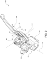
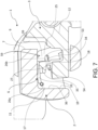
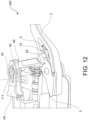
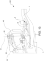
- a lever assembly for a lever device 100 configured to hydraulically actuate a first braking device or front braking device 101 of a handlebar vehicle is indicated by reference numeral 1.
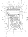
- the lever device 100 comprises a master cylinder body 21 comprising connecting means 20 to constrain the master cylinder body 21 to a handlebar of the handlebar vehicle.
- Said master cylinder body 21 comprises cylinder walls 55 delimiting a cavity or cylinder 23.
- the lever device 100 comprises at least one float or piston 22 operatively associated with the master cylinder body 21, so as to be adapted to slide inside the cavity or cylinder 23 along a thrust direction X-X.
- the float or piston 22 comprises a piston bottom 56 defining, with the cylinder walls 55 of the master cylinder body 21, at least one pressure chamber 57 configured to accommodate an actuating fluid of the first braking device or front braking device 101.
- At least one of the cylinder walls 55 is interrupted to delimit at least one supply channel 58 configured to put in fluid communication the pressure chamber 57 with an associable fluid tank 24.
- the piston bottom 56 is movable with respect to said cylinder walls 55 between at least one end-of-stroke position, in which a volume of said pressure chamber 57 is maximum, and at least a first working position, in which in the at least a first working position, said piston bottom fluidly isolates said pressure chamber 57 from said supply channel 58 pressurizing the actuating fluid in the pressure chamber 57.
- the lever device 100 comprises an elastic return element 5 arranged inside said cavity or cylinder and interposed between said piston bottom 56 and a cylinder seat or shoulder defined by the cylinder walls 55 so as to constantly bias the piston or float 22 elastically towards the end-of-stroke position.
- the elastic return element 5 allows for a return up to the end-of-stroke position of the piston or float 22 upon cessation of the actuation of the lever device 100 by the user.
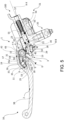
- the lever assembly 1 comprises a primary lever 2 rotatably associable with the master cylinder body 21 so as to rotate about at least one pivot axis Y-Y. Said primary lever is connectable and/or connected, either directly or indirectly, to said float or piston 22.
- the primary lever 2 is rotatable about the at least one pivot axis Y-Y between a primary lever resting position, and at least one primary lever actuation position, in which, in the at least one primary lever actuation position, the primary lever 2 directly or indirectly biases said float or piston 22.
- the primary lever thrust portion 7 in the at least one primary lever actuation position, is in direct or indirect contact with the secondary lever counter-abutment portion 9, so as to bias, by means of the secondary lever or hub 3, the float or piston 22 at least when it is in the at least a first working position.
- the lever assembly 1 comprises an elastic return element 4 of primary lever configured to elastically bias the primary lever 2 to the primary lever resting position.
- the elastic return element 4 of primary lever is a torsional spring comprising at least a first elastic return element winding 32, a first arm 30 of first elastic return element, and a second arm 31 of first elastic return element extending from said first elastic return element winding 32.
- the primary lever 2 comprises a primary lever body 11.
- the primary lever body 11 defines a primary lever recessed housing or seat 16 adapted to accommodate at least partially the elastic return element 4 of primary lever.
- the primary lever body 11 comprises at least a first primary lever connecting element 17.
- the first primary lever connecting element 17 comprises a first primary lever connecting element coupling portion 26a configured to couple the second arm 31 of first elastic return element so that, when the second arm 31 of first elastic return element is coupled to the first primary lever connecting element 17, the elastic return element 4 of primary lever is preassembled to the primary lever 2 irrespective of the connection of the primary lever 2 to the master cylinder body 21.
- the primary lever 2 comprises a primary lever bushing 14 extending from the primary lever body 11 into the housing 16.
- the primary lever bushing 14 is configured to directly or indirectly accommodate a rotation pin 45.
- the rotation pin 45 is configured to connect the lever assembly 1 to a first connecting bracket 46 and a second connecting bracket 47 of the master cylinder body 21 spaced apart along a direction parallel to the pivot rotation axis Y-Y fixing the rotation pin 45 to appropriate perforated seats made in the connecting brackets 46, 47 coaxial to the pivot rotation axis Y-Y.
- the at least a first elastic return element winding 32 is fitted onto the outer surface of the primary lever bushing 14 and abuts against an annular primary lever wall 51 extending about the base of the primary lever bushing 14.
- the elastic return element 4 of primary lever is preassembled to the primary lever 2 irrespective of the connection of the primary lever 2 with the master cylinder body 21 by means of the rotation pin 45.
- the primary lever body 11 comprises a second primary lever connecting element 25.
- the second primary lever connecting element 25 comprises a second primary lever connecting element coupling portion 26b configured to couple the second arm 31 of first elastic return element so that, when the second arm 31 of first elastic return element is coupled to the first primary lever connecting element 17 and to the second primary lever connecting element 25, the elastic return element 4 of primary lever is preassembled to the primary lever 2 irrespective of the connection of the primary lever 2 with the master cylinder body 21.
- the primary lever body 11 comprises an inner housing side wall 19 delimiting the housing 16.
- the primary lever body 11 comprises a bottom housing wall 59 connected to the housing side wall 19, and substantially orthogonal to the direction of the pivot axis Y-Y.
- the inner housing side wall 19 delimits the housing 16, either laterally or circumferentially, with respect to radial directions orthogonal to the direction of the pivot axis Y-Y.
- the inner housing side wall 19 extends forming a concave portion, preferably with concavity facing the pivot axis Y-Y.
- the inner housing side wall 19 comprises a first inner wall portion 36 and a second inner wall portion 39.
- first inner wall portion 36 and a second inner wall portion 39 delimit the housing 16 on opposite sides. In an embodiment, the first inner wall portion 36 and the second inner wall portion 39 delimit the concave portion of the housing on opposite sides. In an embodiment, the first inner wall portion 36 and the second inner wall portion 39 substantially face each other. In an embodiment, in a section of the primary lever body orthogonal to the direction of the pivot axis Y-Y, the inner housing side wall 19 forms at least one U- or V-shaped portion, where the first inner wall portion 36 and the second inner wall portion 39 are on opposite sides of the U- or V-shaped portion and are connected by an inner wall connecting portion, preferably curved.
- first inner wall portion 36 comprises the first primary lever connecting element 17.
- second inner wall portion 39 comprises the second primary lever connecting element 25.
- the second arm 31 of first elastic return element comprises, moving away from the first elastic return element winding 32, an elastic relative-load element 6.
- the elastic relative-load element 6 comprises a first arm 33 of elastic relative-load element and a second arm 34 of elastic relative-load element, where the first arm 33 of elastic relative-load element and the second arm 34 of elastic relative-load element elastically oppose a mutual approach.
- the first arm 33 of elastic relative-load element is coupled to the first primary lever connecting element coupling portion 26a.
- the second arm 34 of elastic relative-load element is coupled to the second primary lever connecting element coupling portion 26b.
- the elastic return element 4 of primary lever is preassembled to the primary lever 2 irrespective of the connection of the primary lever 2 to the master cylinder body 21 by means of the rotation pin 45.
- each primary lever connecting element 17, 25 is a stud which is in relief with respect to an inner housing side wall 19 delimiting the housing 16.
- each primary lever connecting element 17, 25 is a stud which is in relief with respect to a housing bottom side wall 59 delimiting the housing 16.
- each stud is adapted to limit the movements of the elastic return element 4 of primary lever along directions parallel to the pivot axis Y-Y.
- each primary lever connecting element coupling portion 26a, 26b is an undercut portion adapted to limit the movements of the elastic relative-load element 6 along directions parallel to the pivot axis Y-Y.
- said lever assembly 1 comprises a secondary lever or hub 3 rotatably associated with the master cylinder body 21, the secondary lever 3 comprising a secondary lever counter-abutment portion 9.
- the secondary lever or hub 3 is connectable and/or connected, either directly or indirectly, to said float or piston 22.
- the secondary lever 3 is rotatable about the at least one pivot axis Y-Y, or an axis parallel thereto, between a secondary lever resting position, and at least one secondary lever actuation position, where, in the at least one secondary lever actuation position, the secondary lever 3 biases an advancement of the float or piston 22 towards the at least one working position.
- the secondary lever 3 is elastically biased to the resting position by the elastic return element 5.
- the secondary lever 3 can rotate about the same pivot axis Y-Y about which the primary lever 2 is rotatable, or can rotate about a secondary lever pivot axis which is parallel to the at least one pivot axis Y-Y.
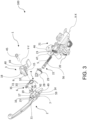
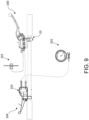
- the secondary lever 3 is operatively connectable to a combined braking mechanism 103 actuatable by a combined-action lever 104 so that the secondary lever 3 is also drivable into rotation from the secondary lever resting position to the at least one secondary lever actuation position by actuating a combined-action lever 104 connected to a second braking device or rear braking device 102 to activate the first braking device 101 and the second braking device 102 in a combined manner irrespective of an actuation of the primary lever 2.
- the secondary lever 3 comprises a combined braking connecting portion 40 operatively connectable to the combined braking mechanism 103, e.g., by means of a shaped metal sheet 64.
- the shaped metal sheet 64 defines a linear guide 65 along which a sliding pin 66 of the combined braking connecting portion 40 is slidably guided when the secondary lever 3 is driven into rotation by the primary lever 2.
- the shaped metal sheet 64 is connectable to an actuating cable of the combined braking mechanism 103, so that by actuating the actuating cable, the shaped metal sheet 64 transmits the actuating force from the actuating cable to the combined braking connecting portion 40 allowing a rotation of the secondary lever 3 irrespective of the actuation of the primary lever 2.
- the secondary lever 3 comprises a secondary lever connecting element 18.
- the secondary lever connecting element 18 comprises a secondary lever connecting element coupling portion 27 configured to couple a distal portion 54 of second arm of elastic relative-load element.
- the secondary lever or hub 3 comprises a secondary lever bushing 15.
- the primary lever bushing 14 comprises a substantially cylindrical bushing body and a through hole coaxial to the pivot axis Y-Y.
- the secondary lever bushing 15 comprises a respective substantially cylindrical body and a through hole coaxial the pivot axis Y-Y.
- the primary lever bushing 14 is made in one piece with the primary lever body 11.
- the primary lever bushing 14 defines a cylindrical primary lever coupling surface on the primary lever body 11.
- the secondary lever bushing 15 is made in one piece with the secondary lever body 12.
- the secondary lever bushing 15 defines a cylindrical secondary lever coupling surface on the secondary lever body 12.
- the primary lever bushing 14 and the secondary lever bushing 15 are coaxial to the pivot axis Y-Y.
- the primary lever bushing 14 is configured to accommodate the secondary lever bushing 15, or vice versa, so as to allow a rotation of the primary lever 2 with respect to the secondary lever 3 about the pivot axis Y-Y when the primary lever bushing 14 and the secondary lever bushing 15 are mutually coupled.
- either the primary lever bushing 14 or the secondary lever bushing 15 is configured to accommodate a rotation pin 45.
- the lever device 100 comprises at least one connecting bracket 46, 47 constrained to the master cylinder body 21 or made in one piece with the master cylinder body to allow a rotatable connection between the master cylinder body and the lever assembly by means of the rotation pin 45.
- the lever device 100 comprises a first connecting bracket 46 and a second connecting bracket 47, where the connecting brackets 46, 47 are constrained to the master cylinder body 21 or made in one piece with the master cylinder body.
- the connecting brackets 46, 47 are spaced apart along a direction parallel to the pivot rotation axis Y-Y and have appropriate pierced seats made in the connecting brackets 46, 47 coaxial with the pivot rotation axis Y-Y to fix the rotation pin 45 to the master cylinder body 21.
- the lever device 100 comprises said rotation pin 45 to connect the lever assembly 1 fixed to the first connecting bracket 46 and to the second connecting bracket 47.
- the first arm 33 of elastic relative-load element and the second arm 34 of elastic relative-load element are coupled to the first primary lever coupling portion 26a and the secondary lever connecting element coupling portion 27, respectively, by biasing the primary lever 2 and the secondary lever 3 along directions transverse to the pivot axis Y-Y thus preventing a separation between the primary lever 2 and the secondary lever 3 along directions parallel to the pivot axis Y-Y.
- the primary lever comprises a primary lever thrust portion 7.
- the lever assembly 1 comprises an elastic relative load element 6 which is connected to the primary lever 2 and/or the secondary lever 3.
- the elastic relative-load element 6 is interposed between a first primary lever connecting element 17 of the primary lever 2 and a secondary lever connecting element 18.
- the elastic relative-load element 6 is configured to apply an elastic spacing action which opposes an approach of the secondary lever counter-abutment portion 9 to the primary lever thrust portion 7, or vice versa, so that when the primary lever 2 and the secondary lever or hub 3 are in the respective resting positions, the elastic relative-load element 6 avoids the direct or indirect rubbing contact between the secondary lever counter-abutment portion 9 and the primary lever thrust portion 7.
- the elastic relative-load element 6 is configured to apply an elastic spacing action which opposes an approach of the secondary lever counter-abutment portion 9 to the primary lever thrust portion 7, or vice versa, so that the primary lever 2 is rotatable about the at least one pivot axis Y-Y between the primary lever resting position and the at least one primary lever actuation position by overcoming the elastic spacing action of the elastic relative load element 6, taking the primary lever thrust portion 7 close to the secondary lever counter-abutment portion 9 until it contacts it either directly or indirectly.
- the elastic relative-load element 6 allows avoiding a direct or indirect contact between the secondary lever counter-abutment portion 9 and the primary lever counter-abutment portion 7 until the elastic spacing action is completely overcome by the rotation of the primary lever 2 under the bias of a user by taking it close to the handlebar, contacting, in the at least one primary lever actuation position, the primary lever counter-abutment portion 7 with the secondary lever counter-abutment portion 9.
- the primary lever thrust portion 7 in the at least one primary lever actuation position, is in direct contact with the secondary lever counter-abutment portion 9, avoiding an interposition between the secondary lever counter-abutment portion 9 and the primary lever thrust portion 7 of non-metal elements subject to wear by rubbing.
- the primary lever connecting element 17 and the secondary lever connecting element 18 are distinct from the primary lever thrust portion 7 and the secondary lever counter-abutment portion 9, respectively.
- the elastic relative-load element 6 biases the first primary lever connecting element 17 and the secondary lever connecting element 18 while keeping a spacing clearance D between the primary lever thrust portion 7 and the secondary lever counter-abutment portion 9 between 0.05 mm and 5 mm, preferably between 0.1 mm and 1 mm.
- said lever device 100 comprises at least one thrust transmission element or actuation pin 29 interposed between the piston or float 22 and the lever assembly 1, in particular the secondary lever 3, and adapted to transmit the thrust action between the lever assembly 1 and the piston or float 22.
- said thrust transmission element 29 comprises a shaft 10 and a push rod 13.
- said thrust transmission element 29 is associated with a dust cuff 28 which prevents impurities from entering into the cavity 23 of the master cylinder body 21.
- the rotation pin 45 comprises a pin guide portion 48 which is a cylindrical portion extending without shoulders at least between the first connecting bracket 46 and the second connecting bracket 47 so that the primary lever bushing 14 and the secondary lever bushing 15 are guided over the entire length of the pin guide portion 48.
- the elastic relative-load element 6 is configured to mutually connect the primary lever 2 and the secondary lever or hub 3 irrespective of a connection of the primary lever 2 and the secondary lever 3 with the master cylinder body 21 by means of said rotation pin 45.
- the primary lever 2 comprises a primary lever stop wall 42 and where the secondary lever 3 comprises a secondary lever stop counter-wall 43.
- the elastic relative-load element 6 is interposed between the first primary lever connecting element 17 of the primary lever 2 and the secondary lever connecting element 18, by rotationally biasing the secondary lever counter-abutment portion 9 about the pivot axis Y-Y away from the primary lever thrust portion 7 and by rotationally biasing the primary lever stop wall 42 against the secondary lever counter-abutment wall 43 about the pivot axis Y-Y, or vice versa, defining the resting position of the primary lever 3 and the secondary lever 2, and mutually connecting the primary lever 2 and the secondary lever or hub 3 when preassembled without being connected to the master cylinder body 21, and/or mutually connecting the primary lever 2 and the secondary lever or hub 3 by friction between the primary lever stop wall 42 abutting against the secondary lever stop counter-wall 43 which avoids separation of the primary lever 2 from the secondary lever 3 along a direction parallel to the pivot axi
- the primary lever bushing 14 accommodates the secondary lever bushing 15.
- the primary lever bushing 14 comprises a bushing end 49 configured to abut against an annular seat 50 defined outside the base or root of the secondary lever bushing 15.
- the primary lever body 11 defines a primary lever recessed housing or seat 16 adapted to accommodate the elastic relative-load element 6.
- first arm 30 of first elastic return element is configured to abut against a portion of the master cylinder body 21.
- the second arm 31 of first elastic return element is configured to abut against a portion of the primary lever 2, preferably against the inner housing side wall 19.
- the at least a first elastic return element winding 32 is fitted onto the outer surface of the primary lever bushing 14 and abuts between an annular secondary lever wall 52, extending about the base of the secondary lever bushing 15, and an annular primary lever wall 51 extending about the base of the primary lever bushing 14.
- the at least a first elastic return element winding 32 comprises a plurality of windings coaxial to the pivot Y-Y.
- the plurality of windings is configured to provide an axial thrust between the primary lever 2 and the secondary lever 3 so as to correct any clearance along directions parallel to the pivot axis Y-Y between the lever assembly 1 and the master cylinder body 21.
- the primary lever 2 comprises a second primary lever connecting element 25.
- the second primary lever connecting element 25 is made on the second inner wall portion 39.
- the first primary lever connecting element 17 is made on the first inner wall portion 36.
- the secondary lever connecting element 18 comprises a secondary lever connecting element coupling portion 27 configured to couple a distal portion 54 of second arm of elastic relative-load element.
- first arm 33 of elastic relative-load element and the second arm 34 of elastic relative-load element are coupled to the respective coupling portions 26a, 26b, 27 by biasing the primary lever 2 and the secondary lever 3 along directions transverse to the pivot axis Y-Y of the lever assembly 1, a separation between the primary lever 2 and the secondary lever 3 along directions parallel to the pivot axis Y-Y is prevented by moving the primary lever 2 and the secondary lever 3..
- each primary lever connecting element 17, 25 is a stud which is in relief with respect to an inner housing side wall 19 and each stud is adapted to limit the movements of the elastic relative-load element 6 along directions parallel to the pivot axis Y-Y.
- the first primary lever connecting element 17 is a first stud or first element in relief along a direction orthogonal to the pivot axis Y-Y with respect to the first inner wall portion 36, which comprises a groove adapted to accommodate at least one portion of the first arm 33 of elastic relative-load element.
- the second primary lever connecting element 25 is a second stud or second element in relief along a direction orthogonal to the pivot axis Y-Y with respect to the second inner wall portion 39, which comprises a groove adapted to accommodate a proximal portion 53 of second arm of elastic relative-load element of the second arm 34 of elastic relative-load element.
- the secondary lever connecting element 18 projects into the housing 16 when the primary lever 2 is connected to the secondary lever 3.
- each primary lever connecting element coupling portion 27 is an undercut portion adapted to limit the movements of the elastic relative-load element 6 along directions parallel to the pivot axis Y-Y.
- each primary lever connecting element coupling portion 26 comprises a groove made in the respective primary lever connecting element 17, 25, where the groove is in a plane transverse to the pivot axis Y-Y.
- each secondary lever connecting element coupling portion 27 comprises a groove made in the respective secondary lever connecting element 18.
- the groove is in a plane transverse to the pivot axis Y-Y.
- the elastic relative-load element 6 is a torsional elastic element.
- the elastic relative-load element 6 is a wire spring.
- the elastic relative-load element 6 comprises at least one elastic relative-load element winding 35 wound about a direction parallel to the pivot axis Y-Y, where the first arm 33 of elastic relative-load element and the second arm 34 of elastic relative-load element extend from the at least one elastic relative-load element winding 35 to bias the primary lever 2 and the secondary lever 3 elastically.
- the elastic return element 4 of primary lever is a wire spring.
- the elastic return element 4 of primary lever and the elastic relative-load element 6 are integrated, preferably made from a wire.
- the primary lever 2 comprises a grippable portion 38 of primary lever configured to be gripped by a user to rotate the primary lever 2 with respect to the master cylinder body 21 towards the handlebar in the plurality of primary lever actuation positions.
- the primary lever 2 comprises a primary lever anti-rotation portion 8 configured to abut against a first master cylinder body abutment portion 41 of the master cylinder body 21 defining the resting position of the primary lever and preventing a rotation of the primary lever 2 away from the handlebar towards the master cylinder body 21.
- the secondary lever 3 comprises a combined braking connecting portion 40 configured to operatively connect the secondary lever 3 to the combined braking mechanism 103.
- the secondary lever 3 comprises a secondary lever anti-rotation portion 44 configured to abut against a second master cylinder body abutment portion 37 of the master cylinder body 21 defining the resting position of the secondary lever and preventing a rotation of the secondary lever 3 away from the handlebar towards the master cylinder body 21.
- the second abutment portion 37 of master cylinder body and the first abutment portion 41 of master cylinder body belong to the same master cylinder body surface.
- the at least one elastic relative-load element winding 35 is accommodated inside the housing 16.
- the first arm 33 of elastic relative-load element is coupled to the first primary lever connecting element 17 and the second arm 34 of elastic relative-load element is coupled, with a portion 53 thereof close to the at least one elastic relative-load element winding 35, to the second primary lever connecting element 25 so that when the elastic relative-load element 6 is inserted into the housing 16 of the primary lever 2 coupled to the first primary lever connecting element 17 and to the second primary lever connecting element 25, with the first arm 33 of elastic relative-load element elastically abutting against the first primary lever connecting element 17 and with the second arm 34 of elastic relative-load element elastically abutting against the second connecting element 25 of primary lever, the elastic relative-load element 6 is connected to the primary lever 2 avoiding possible gravity falling from the housing 16 irrespective of the presence of the secondary lever 3 and/or irrespective of the connection of the lever assembly 1 with the master cylinder body 21.
- the present invention also relates to a lever device 100 configured to hydraulically actuate a first braking device or front braking device 101 of a handlebar vehicle.
- the lever device comprises a lever assembly 1 according to any one the previously described embodiments.
- the lever device 100 comprises a master cylinder body 21 comprising connecting means 20 to constrain the master cylinder body 21 to a handlebar of the handlebar vehicle, said master cylinder body 21 comprising cylinder walls 55 delimiting a cavity or cylinder 23.
- the lever device 100 comprises at least one float or piston 22, operatively associated with the master cylinder body 21, so as to be adapted to slide inside the cavity or cylinder 23 along a thrust direction X-X, said float or piston 22 comprising a piston bottom 56 defining, with the cylinder walls 55 of the master cylinder body 21, at least one pressure chamber 57 configured to accommodate an actuating fluid of the first braking device or front braking device 101, where at least one of the cylinder walls 55 is interrupted to delimit at least one supply channel 58 configured to put the pressure chamber 57 in fluid communication with at least one associable fluid tank 24.
- the piston bottom 56 is movable with respect to said cylinder walls 55 between at least one end-of-stroke position, in which a volume of said pressure chamber 57 is maximum, and at least a first working position, in which said piston bottom fluidly isolates said pressure chamber 57 from said supply channel 58 pressurizing the actuating fluid in the pressure chamber 57.
- the lever device 100 comprises an elastic return element 5 arranged inside said cavity or cylinder and interposed between said piston bottom 56 and a cylinder seat defined by the cylinder walls 55 so as to constantly bias the piston or float 22 elastically towards the end-of-stroke position.
- the lever assembly 1 is rotatably associated with the master cylinder body 21 so as to rotate about at least one pivot axis Y-Y.
- the lever assembly 1 is connected either directly or indirectly to said float or piston 22.
- the present invention also relates to a braking system for a handlebar vehicle comprising a lever device 100 according to any one of the previously described embodiments, connected or connectable to the handlebar of the handlebar vehicle.
- the braking system comprises a front braking device 101 operatively connected to the lever device 100, preferably a disc brake.
- the braking system comprises a combinable action lever device comprising a combined action lever 104 and a combined braking mechanism 103 actuatable by the combined action lever 104.
- the braking system comprises a rear braking device 102, preferably a drum brake, where the combined braking mechanism is operatively connected to the rear braking device 102 and also to the first braking device 101 by means of the lever device 100, so that the actuation of the combined-action lever device activates the first braking device 101 and the second braking device 102 in a combined manner irrespective of an actuation of the primary lever 2.
- the present invention also relates to a spring assembly for a lever assembly 1 of a lever device 100.
- the lever device 100 is according to one or more of the previously described embodiments.
- the lever device 100 is configured to hydraulically actuate a first braking device or front braking device 101 of a handlebar vehicle, where said lever assembly 1 comprises a primary lever 2 and a secondary lever 3 rotatably associable with a master cylinder body 21 to rotate about a pivot axis Y-Y, the primary lever comprising a primary lever thrust portion 7, the secondary lever or hub 3 being connectable directly or indirectly to a float or piston 22 associated with the master cylinder body 21, the secondary lever 3 comprising a secondary lever counter-abutment portion 9.
- Said spring assembly comprises an elastic return element 4 of primary lever adapted to be interposed between the master cylinder body 21 and the primary lever and configured to elastically bias the primary lever 2 to a primary lever resting position.
- Said elastic return element 4 of primary lever comprises a first arm 30 of first elastic return element and a second arm 31 of first elastic return element, where the first arm 30 of first elastic return element is configured to abut against a portion of the master cylinder 21, and where the second arm 31 of first elastic return element is configured to abut against a portion of the primary lever 2.
- Said spring assembly comprises an elastic relative-load element 6 adapted to be interposed between a first primary lever connecting element 17 of the primary lever 2 and a secondary lever connecting element 18, where the elastic relative-load element 6 is configured to apply an elastic spacing action which opposes an approach of the secondary lever counter-abutment portion 9 to the primary lever thrust portion 7 or vice versa.
- the elastic relative-load element 6 comprises a first arm 33 of elastic relative-load element adapted to be connected to the first primary lever connecting element 17 and a second arm 34 of elastic relative-load element adapted to be connected to the secondary lever connecting element 18.
- the first arm 33 of elastic relative-load element is connected to the second arm 31 of first elastic return element.
- the first arm 33 of elastic relative-load element is integrated, preferably in one piece, with the second arm 31 of first elastic return element.
- the elastic relative-load element 6 and the elastic return element 4 of primary lever are integrated, preferably made by bending the same metal wire.
- the elastic relative-load element 6 is configured to be interposed between a first primary lever connecting element 17 of the primary lever 2 and a secondary lever connecting element 18, so that, when the primary lever 2 and the secondary lever or hub 3 are in the respective resting positions, the elastic relative-load element 6 avoids a direct or indirect contact by rubbing between the secondary lever counter-abutment portion 9 and the primary lever thrust portion 7, and so that the primary lever 2 is rotatable about the at least one pivot axis Y-Y between the primary lever resting position and the at least one primary lever actuation position, avoiding a direct or indirect contact between the secondary lever counter-abutment portion 9 and the primary lever thrust portion 7.
- the elastic return element 4 of primary lever is a torsional spring comprising at least a first elastic return element winding 32, where the first arm 30 of first elastic return element and the second arm 31 of first elastic return element extend from said a first elastic return element winding 32.
- the elastic relative-load element 6 comprises at least one elastic relative-load element winding 35 wound about a direction parallel to the pivot axis Y-Y, where a first arm 33 of elastic relative-load element, and a second arm 34 of elastic relative-load element extend from the at least one elastic relative-load element winding 35 to elastically bias the primary lever 2 and the secondary lever 3.
- the at least a first elastic return element winding 32 comprises a plurality of windings coaxial to the pivot Y-Y, where the plurality of windings is configured to provide an axial thrust between the primary lever 2 and the secondary lever 3 so as to correct any clearance along directions parallel to the pivot axis Y-Y between the lever assembly 1 and the master cylinder body 21.
- the at least a first elastic return element winding 32 and the at least one elastic relative-load element winding 35 extend helically about axes parallel to each other and parallel to the direction of the pivot axis Y-Y.
- the first arm 30 of first elastic return element extends from the at least a first elastic return element winding 32 with a first fold 60 in a first plane perpendicular to the direction of the pivot axis Y-Y, a second fold 61 in a second plane perpendicular to the first plane, a curved portion 62, preferably forming a semi-circumference, with concavity opposite to the second fold 61 and facing the thrust direction X-X, and a first arm abutment portion 63 bent on the opposite side with respect to the curved portion 62.
- the first arm 30 of first elastic return element forms a U-bent portion or curved portion 62, adapted to be arranged in a plane substantially orthogonal to the thrust direction X-X and substantially parallel to a direction coincident with or parallel to the direction of the pivot axis Y-Y, when the spring assembly is assembled to the lever device 100.
Landscapes
- Engineering & Computer Science (AREA)
- Mechanical Engineering (AREA)
- Transportation (AREA)
- Physics & Mathematics (AREA)
- Chemical & Material Sciences (AREA)
- Combustion & Propulsion (AREA)
- General Physics & Mathematics (AREA)
- Automation & Control Theory (AREA)
- Fluid Mechanics (AREA)
- Transmission Of Braking Force In Braking Systems (AREA)
- Braking Elements And Transmission Devices (AREA)
- Mechanical Control Devices (AREA)
Applications Claiming Priority (1)
| Application Number | Priority Date | Filing Date | Title |
|---|---|---|---|
| IT202300008247 | 2023-04-27 |
Publications (1)
| Publication Number | Publication Date |
|---|---|
| EP4454960A1 true EP4454960A1 (de) | 2024-10-30 |
Family
ID=88098036
Family Applications (1)
| Application Number | Title | Priority Date | Filing Date |
|---|---|---|---|
| EP24171714.9A Pending EP4454960A1 (de) | 2023-04-27 | 2024-04-22 | Hebelanordnung, hebelvorrichtung |
Country Status (4)
| Country | Link |
|---|---|
| US (1) | US20240359666A1 (de) |
| EP (1) | EP4454960A1 (de) |
| JP (1) | JP2024159662A (de) |
| CN (1) | CN118850016A (de) |
Citations (10)
| Publication number | Priority date | Publication date | Assignee | Title |
|---|---|---|---|---|
| US6393936B1 (en) * | 1999-07-15 | 2002-05-28 | Robert L. Barnett | Collapsible control lever |
| JP3754514B2 (ja) | 1996-12-12 | 2006-03-15 | 本田技研工業株式会社 | 自動二輪車用前後連動ブレーキ装置 |
| US20060070483A1 (en) * | 2004-10-05 | 2006-04-06 | Dimsey James J | Brake and clutch lever height adjusters |
| US8061234B2 (en) * | 2005-08-30 | 2011-11-22 | Roberto Lavezzi | Adjustment device for motorcycle master cylinders |
| US8276477B2 (en) * | 2004-12-30 | 2012-10-02 | Freni Brembo S.P.A. | Collapsible control lever device |
| EP2367716B1 (de) | 2008-12-24 | 2012-10-03 | Freni Brembo S.p.A. | Betätigungsvorrichtung für einen klappbaren hebel |
| US20150284049A1 (en) * | 2014-04-04 | 2015-10-08 | Sram, Llc | Control assembly for a wireless electromechanical bicycle shifting system |
| US20170305493A1 (en) * | 2016-04-25 | 2017-10-26 | Shimano Inc. | Bicycle operating device |
| WO2019186349A1 (en) * | 2018-03-26 | 2019-10-03 | Tvs Motor Company Limited | A braking system for a motor vehicle |
| US20220269299A1 (en) * | 2021-02-24 | 2022-08-25 | Akwel | Pedal assembly for pedal braking control of a motor vehicle |
-
2024
- 2024-04-22 EP EP24171714.9A patent/EP4454960A1/de active Pending
- 2024-04-25 US US18/645,454 patent/US20240359666A1/en active Pending
- 2024-04-25 JP JP2024071743A patent/JP2024159662A/ja active Pending
- 2024-04-28 CN CN202410522259.6A patent/CN118850016A/zh active Pending
Patent Citations (10)
| Publication number | Priority date | Publication date | Assignee | Title |
|---|---|---|---|---|
| JP3754514B2 (ja) | 1996-12-12 | 2006-03-15 | 本田技研工業株式会社 | 自動二輪車用前後連動ブレーキ装置 |
| US6393936B1 (en) * | 1999-07-15 | 2002-05-28 | Robert L. Barnett | Collapsible control lever |
| US20060070483A1 (en) * | 2004-10-05 | 2006-04-06 | Dimsey James J | Brake and clutch lever height adjusters |
| US8276477B2 (en) * | 2004-12-30 | 2012-10-02 | Freni Brembo S.P.A. | Collapsible control lever device |
| US8061234B2 (en) * | 2005-08-30 | 2011-11-22 | Roberto Lavezzi | Adjustment device for motorcycle master cylinders |
| EP2367716B1 (de) | 2008-12-24 | 2012-10-03 | Freni Brembo S.p.A. | Betätigungsvorrichtung für einen klappbaren hebel |
| US20150284049A1 (en) * | 2014-04-04 | 2015-10-08 | Sram, Llc | Control assembly for a wireless electromechanical bicycle shifting system |
| US20170305493A1 (en) * | 2016-04-25 | 2017-10-26 | Shimano Inc. | Bicycle operating device |
| WO2019186349A1 (en) * | 2018-03-26 | 2019-10-03 | Tvs Motor Company Limited | A braking system for a motor vehicle |
| US20220269299A1 (en) * | 2021-02-24 | 2022-08-25 | Akwel | Pedal assembly for pedal braking control of a motor vehicle |
Also Published As
| Publication number | Publication date |
|---|---|
| JP2024159662A (ja) | 2024-11-08 |
| CN118850016A (zh) | 2024-10-29 |
| US20240359666A1 (en) | 2024-10-31 |
Similar Documents
| Publication | Publication Date | Title |
|---|---|---|
| EP0327587B1 (de) | Hydraulisches betätigungssystem für eine kupplung | |
| US4265340A (en) | Disk brake mounting | |
| KR20130004131A (ko) | 디스크 브레이크 | |
| CN101303054A (zh) | 盘式制动装置 | |
| GB2132144A (en) | Vehicle wheel axle and brake mounting assembly | |
| US4903806A (en) | Hydraulically actuated release mechanism for a clutch | |
| EP4454960A1 (de) | Hebelanordnung, hebelvorrichtung | |
| WO2023187667A1 (en) | Integrated control unit for a hydraulic brake of a handlebar-guided vehicle | |
| EP0236420A1 (de) | Anordnung in einer reibungskupplung | |
| EP4454984A1 (de) | Hebelvorrichtung, bremssystem, federanordnung | |
| US6851524B2 (en) | Disc brake for motor vehicles | |
| EP1703165A2 (de) | Nachstelleinrichtung für eine pneumatische Scheibenbremse | |
| KR101532434B1 (ko) | 유압 제어 해제 장치 | |
| EP0217589A2 (de) | Schienenfahrzeugbremsvorrichtung | |
| JP2006002867A (ja) | ディスクブレーキ装置 | |
| US6044950A (en) | Hydraulic clutch control actuator in particular of motor vehicle | |
| JP5759793B2 (ja) | ディスクブレーキ | |
| EP0418232A1 (de) | Anordnung zum zentrieren einer lagereinheit einer mechanisch ein- und ausrückbaren kupplung | |
| CN100548786C (zh) | 离合器操作助力装置和装配有该装置的车辆 | |
| CN114728649B (zh) | 制动促动器、特别是商用车辆的机电制动促动器 | |
| JPS62166155A (ja) | 液圧ブ−スタ | |
| US4446949A (en) | Connecting rod and piston device for a brake slack adjuster | |
| EP3752397B1 (de) | Kombiniertes vorder-/hinterbremssystem für kraftfahrzeug und kraftfahrzeug mit einem derartigen system | |
| JP2006250325A (ja) | ディスクブレーキ装置 | |
| KR940002739Y1 (ko) | 철도차량의 브레이크 이완 조정 장치 |
Legal Events
| Date | Code | Title | Description |
|---|---|---|---|
| PUAI | Public reference made under article 153(3) epc to a published international application that has entered the european phase |
Free format text: ORIGINAL CODE: 0009012 |
|
| STAA | Information on the status of an ep patent application or granted ep patent |
Free format text: STATUS: THE APPLICATION HAS BEEN PUBLISHED |
|
| AK | Designated contracting states |
Kind code of ref document: A1 Designated state(s): AL AT BE BG CH CY CZ DE DK EE ES FI FR GB GR HR HU IE IS IT LI LT LU LV MC ME MK MT NL NO PL PT RO RS SE SI SK SM TR |
|
| STAA | Information on the status of an ep patent application or granted ep patent |
Free format text: STATUS: REQUEST FOR EXAMINATION WAS MADE |
|
| 17P | Request for examination filed |
Effective date: 20250415 |
|
| RIN1 | Information on inventor provided before grant (corrected) |
Inventor name: COLOMBO, MARCELLO Inventor name: GIRLANDA, ENRICO |
|
| GRAP | Despatch of communication of intention to grant a patent |
Free format text: ORIGINAL CODE: EPIDOSNIGR1 |
|
| STAA | Information on the status of an ep patent application or granted ep patent |
Free format text: STATUS: GRANT OF PATENT IS INTENDED |