EP4454923A1 - Improved wheel for a wheel hub having integrated electric traction. - Google Patents
Improved wheel for a wheel hub having integrated electric traction. Download PDFInfo
- Publication number
- EP4454923A1 EP4454923A1 EP24171853.5A EP24171853A EP4454923A1 EP 4454923 A1 EP4454923 A1 EP 4454923A1 EP 24171853 A EP24171853 A EP 24171853A EP 4454923 A1 EP4454923 A1 EP 4454923A1
- Authority
- EP
- European Patent Office
- Prior art keywords
- wheel
- wheel hub
- axle
- axis
- rim
- Prior art date
- Legal status (The legal status is an assumption and is not a legal conclusion. Google has not performed a legal analysis and makes no representation as to the accuracy of the status listed.)
- Granted
Links
Images


Classifications
-
- B—PERFORMING OPERATIONS; TRANSPORTING
- B60—VEHICLES IN GENERAL
- B60K—ARRANGEMENT OR MOUNTING OF PROPULSION UNITS OR OF TRANSMISSIONS IN VEHICLES; ARRANGEMENT OR MOUNTING OF PLURAL DIVERSE PRIME-MOVERS IN VEHICLES; AUXILIARY DRIVES FOR VEHICLES; INSTRUMENTATION OR DASHBOARDS FOR VEHICLES; ARRANGEMENTS IN CONNECTION WITH COOLING, AIR INTAKE, GAS EXHAUST OR FUEL SUPPLY OF PROPULSION UNITS IN VEHICLES
- B60K17/00—Arrangement or mounting of transmissions in vehicles
-
- B—PERFORMING OPERATIONS; TRANSPORTING
- B60—VEHICLES IN GENERAL
- B60B—VEHICLE WHEELS; CASTORS; AXLES FOR WHEELS OR CASTORS; INCREASING WHEEL ADHESION
- B60B3/00—Disc wheels, i.e. wheels with load-supporting disc body
- B60B3/002—Disc wheels, i.e. wheels with load-supporting disc body characterised by the shape of the disc
- B60B3/007—Disc wheels, i.e. wheels with load-supporting disc body characterised by the shape of the disc in the intermediate section
-
- B—PERFORMING OPERATIONS; TRANSPORTING
- B60—VEHICLES IN GENERAL
- B60B—VEHICLE WHEELS; CASTORS; AXLES FOR WHEELS OR CASTORS; INCREASING WHEEL ADHESION
- B60B3/00—Disc wheels, i.e. wheels with load-supporting disc body
- B60B3/04—Disc wheels, i.e. wheels with load-supporting disc body with a single disc body not integral with rim, i.e. disc body and rim being manufactured independently and then permanently attached to each other in a second step, e.g. by welding
-
- B—PERFORMING OPERATIONS; TRANSPORTING
- B60—VEHICLES IN GENERAL
- B60K—ARRANGEMENT OR MOUNTING OF PROPULSION UNITS OR OF TRANSMISSIONS IN VEHICLES; ARRANGEMENT OR MOUNTING OF PLURAL DIVERSE PRIME-MOVERS IN VEHICLES; AUXILIARY DRIVES FOR VEHICLES; INSTRUMENTATION OR DASHBOARDS FOR VEHICLES; ARRANGEMENTS IN CONNECTION WITH COOLING, AIR INTAKE, GAS EXHAUST OR FUEL SUPPLY OF PROPULSION UNITS IN VEHICLES
- B60K17/00—Arrangement or mounting of transmissions in vehicles
- B60K17/04—Arrangement or mounting of transmissions in vehicles characterised by arrangement, location or kind of gearing
- B60K17/043—Transmission unit disposed in on near the vehicle wheel, or between the differential gear unit and the wheel
- B60K17/046—Transmission unit disposed in on near the vehicle wheel, or between the differential gear unit and the wheel with planetary gearing having orbital motion
-
- B—PERFORMING OPERATIONS; TRANSPORTING
- B60—VEHICLES IN GENERAL
- B60K—ARRANGEMENT OR MOUNTING OF PROPULSION UNITS OR OF TRANSMISSIONS IN VEHICLES; ARRANGEMENT OR MOUNTING OF PLURAL DIVERSE PRIME-MOVERS IN VEHICLES; AUXILIARY DRIVES FOR VEHICLES; INSTRUMENTATION OR DASHBOARDS FOR VEHICLES; ARRANGEMENTS IN CONNECTION WITH COOLING, AIR INTAKE, GAS EXHAUST OR FUEL SUPPLY OF PROPULSION UNITS IN VEHICLES
- B60K7/00—Disposition of motor in, or adjacent to, traction wheel
- B60K7/0007—Disposition of motor in, or adjacent to, traction wheel the motor being electric
-
- B—PERFORMING OPERATIONS; TRANSPORTING
- B60—VEHICLES IN GENERAL
- B60K—ARRANGEMENT OR MOUNTING OF PROPULSION UNITS OR OF TRANSMISSIONS IN VEHICLES; ARRANGEMENT OR MOUNTING OF PLURAL DIVERSE PRIME-MOVERS IN VEHICLES; AUXILIARY DRIVES FOR VEHICLES; INSTRUMENTATION OR DASHBOARDS FOR VEHICLES; ARRANGEMENTS IN CONNECTION WITH COOLING, AIR INTAKE, GAS EXHAUST OR FUEL SUPPLY OF PROPULSION UNITS IN VEHICLES
- B60K7/00—Disposition of motor in, or adjacent to, traction wheel
- B60K2007/0061—Disposition of motor in, or adjacent to, traction wheel the motor axle being parallel to the wheel axle
Definitions
- the present invention relates to a vehicle wheel, in particular a wheel for a wheel hub having integrated electric traction for an axle of a heavy vehicle.
- Heavy goods vehicles for road transport for example trucks, tend to be increasingly electrified to reduce their pollutant emissions.
- such vehicles can be hybrid vehicles or purely electric vehicles.
- the electric vehicles comprise at least one electric axle, viz., an axle provided with electric machines such as motors/generators configured to impart a torque to the wheel hubs to allow the movement thereof or to recharge the battery modules of the vehicle when the latter is braking.
- electric machines such as motors/generators configured to impart a torque to the wheel hubs to allow the movement thereof or to recharge the battery modules of the vehicle when the latter is braking.
- the aim of the present invention is to fulfil the above-mentioned needs in an optimised and cost-effective manner.
- an axle of a vehicle preferably a heavy vehicle, for example a truck and not illustrated, comprising essentially a central portion 2 and a pair of end portions 3, 4 connected by opposite parts to the central portion 2, preferably rigidly, along a longitudinal axis A thereof, is referred to with the number 1.
- the central portion 2 is advantageously hollow so as to define a space 5 suitable for housing functional elements of the vehicle as described below.
- the end portions 3, 4 are equally hollow so as to define a continuous space 5 along the entire extension of the axle 1 along the axis A.
- the end portions 3, 4 are provided with openings 6 configured to allow access to the space 5 as described below.
- the axle 1 comprises at least one flange 7 arranged near each of the end portions 3, 4 and rigidly carried by these or, as in the illustrated case, by the central portion 2 and configured to support operating elements of the vehicle, such as mechanical brakes or sensor means.
- the axle 1 comprises a pair of wheel hubs 10 comprising a fixed portion 8 rigidly carried by the respective end portion 3, 4 and a movable portion 9 rotationally carried in a free manner by the respective end portion 3, 4.
- wheel hubs 10 With regard to the wheel hubs 10, reference will be made to only one of them for the sake of simplicity, for example the left one, and the considerations below also apply in the same manner to the right wheel hub, of course, as the structure described herein is mirrored with respect to a longitudinal plane of the vehicle.
- the fixed portion 8 is advantageously cup-shaped and comprises a radial wall 8' connected to the end portion 4 and extending perpendicularly to the longitudinal axis A and a cylindrical wall 8" extending starting from the radial wall 8' towards the vehicle, viz., towards the intermediate portion 2 of the axle 1.
- the radial wall 8' is advantageously connected to the end portion 4 by means of a rigid connection, such as an interference fit connection.
- a rigid connection such as an interference fit connection.
- the radial wall is 8' made in a single piece with the cylindrical wall 8''.
- the cylindrical wall 8'' is supported, on the opposite side of the radial wall 8' with respect to the movable portion 9, in a rotationally free manner by supporting means 11 such as rolling bearings.
- the cylindrical wall 8'' cooperates with the supporting means 11 by means of a supporting element 12 rigidly connected to the cylindrical wall 8'' and extending radially towards the aforesaid supporting means 11.
- the cylindrical wall 8'' cooperates as described above with the movable portion 9 sealingly by sealing means 13, such as rotating sealing rings, so as to delimit a space 14 isolated from the external environment radially delimited around the axis A by the cylindrical wall 8'' and axially delimited by the radial wall 8' and by the movable portion 9.
- sealing means 13 such as rotating sealing rings
- the wheel hub 10 comprises, housed in the space 14, an electric machine 15 provided with a stator 15' and a rotor 15" operatively driven by the stator 15'' and a transmission 16 operatively connecting the rotor 15" to the movable portion 9 so as to vary the transmitted speed/torque thereof with respect to that originally provided to the rotor 15".
- stator 15' is rigidly carried by the fixed portion 8, in particular by the cylindrical wall 8'' and therefore extends along the axis A within the space 14.
- the transmission 16 is advantageously sized so as to be housed radially within the rotor 15'' and particularly also axially comprised by the rotor 15''.
- the rotor 15'' is connected to a rotor support 17 carried in a rotationally free manner with respect to the fixed portion 8, in particular with respect to the radial wall 8', viz., to a flanged portion extending with respect thereto.
- the rotor support 17 extends radially within the rotor 15 and substantially has the shape of an annular disc housed around the end portion 4.
- the rotor support 17 is operatively connected by means of the transmission 16 to the movable portion 9.
- the transmission 16 comprises a gear, advantageously a differential gear.
- the transmission 16 comprises a first conical gear wheel 21 rigidly connected to the rotor support 17 and rotationally free with respect to the end 4, a second conical gear wheel 22 rigidly carried by the end 4 and a plurality of planetary gears 23 operatively cooperating with the first and the second conical gear wheels 21, 22.
- the planetary gears 23 can be in various number and are supported in a rotationally free manner with respect to the plane of axis B perpendicular to the axis A by means of respective pins 24.
- Each pin 23 is rigidly carried by a planetary carrier 25 rigidly connected to the movable portion 9.
- the transmission 16 is provided with sealing means 13, for example carried between the first gear wheel 21 and the end 4 further configured to isolate the space 14.
- the space 14 can be supplied with lubricating fluid, such as oil, by means of a nozzle 26, for example, carried by the rotating portion 9 so as to lubricate the transmission 16.
- lubricating fluid such as oil
- the movable portion 9, as mentioned above, is supported in a rotationally free manner by supporting means 12, such as rolling bearings, on the end 4.
- supporting means 12 such as rolling bearings
- it comprises a main movable portion 9' and an auxiliary movable portion 9" rigidly connected to each other.
- the main movable portion 9' essentially comprises a main portion 9a, preferably an annular disc, cooperating with the aforesaid supporting means 12 and a first flanged portion 9b extending cantilevered axially along the axis A with respect to the main portion 9a and rigidly connected to the planetary carrier 25. Consequently, the first flanged portion 9b extends radially within the rotor 15".
- the main movable portion 9' comprises a second flanged portion 9c extending radially from the main portion 9a and rigidly connected to a wheel 30 as described in detail below.
- the auxiliary movable portion 9'' extends on the opposite side of the fixed portion 8 and is configured to provide support for operating elements of the vehicle, such as sensors or other elements which must be integral with the movable portion 9.
- the wheel hub 10 further comprises a conditioning system 40 configured to cool the fixed portion 8, viz., the stator 15' connected thereto.
- the conditioning system 40 is a fluidised conditioning system.
- the conditioning system 40 comprises a plurality of conduits 41 in which a conditioning fluid flows and adjacent to the stator 15' .
- conduits 41 are integrated in the fixed portion 8, viz., in the cylindrical portion 8".
- conduits 41 are made as grooves 42 defined radially recessed with respect to the surface opposite the space 14 of the cylindrical portion 8" and isolated from the external environment by means of a lid 43 rigidly carried on the cylindrical portion, sealingly, so as to delimit such conduits 41.
- the conduits 41 are fluidically connected to a delivery conduit 44 and a return conduit 45 configured to supply the low-temperature conditioning fluid and collect the high-temperature conditioning fluid once it has flowed in the conduits 41 to cool the fixed portion 8.
- the conduits 41 are essentially circumferential around the axis A and advantageously with a quadrangular section. In particular, they are equal in size to each other and equally spaced along the axis A.
- conduits 41 are fluidically connected to the delivery conduit 44 and the return conduit 45 by means of respective manifolds 46 advantageously integrated in the fixed portion 8, viz., in the cylindrical portion 8".
- such manifolds 46 are made as a single groove 47 defined radially recessed with respect to the surface opposite the space 14 of the cylindrical portion 8'' and isolated from the external environment by means of the same lid 43 delimiting the conduits 41.
- the groove 47 extends along the axis A for the entire length of the cylindrical portion 8" in which the conduits 41 are made so as to be able to fluidically communicate with each of the latter.
- the delivery and return conduits 44, 45 are fluidically connected to a heat exchanger system (not shown) of the vehicle, for example a passive heat exchanger such as an air cooler or an active device such as a refrigeration-type conditioning circuit.
- a passive heat exchanger such as an air cooler or an active device such as a refrigeration-type conditioning circuit.
- the delivery conduits 44, 45 are housed within the space 5 and extend between respective fluidic connectors 48, as visible in figure 7 , configured to allow the connection with further pipes (not illustrated) connecting to the aforesaid heat exchanger of the vehicle.
- the fluidic connectors 48 are made in the central portion 2 of the axle 1.
- the delivery conduits 44, 45 exit from the space 5 by means of the opening 6 and are directed to connect to the manifolds 46 within a space 51 delimited between the fixed portion 8 and a head element 52 connected thereto.
- Such a space 51 is therefore radially delimited by the fixed portion 8, in particular by a flange extending between the cylindrical portion 8'' and the radial portion 8' on the opposite side of the cylindrical portion 8'' and axially delimited by the head element 52 and by the radial portion 8' .
- the head element 52 in the embodiment illustrated, is rigidly connected to the lid 43.
- the lid 43 is rigidly connected to the lid 43.
- it could be made in a single piece therewith in an alternative embodiment.
- the wheel hub 10 further comprises cables 53 for the electrical connection of the electric machine 15 with electrical energy storage means (not illustrated) such as a battery, of the vehicle.
- electrical energy storage means such as a battery
- the cables 53 are advantageously housed within the space 5 and extend between respective electrical connectors 54, as visible in figure 7 , configured to allow the connection with further cables (not illustrated) connecting to the aforesaid electrical energy storage means.
- the electrical connectors 54 are made in the central portion 2 of the axle 1.
- the cables 43 exit from the space 5 by means of the opening 6 in the aforesaid space 51 and pass through a dedicated, sealed opening in the space 14, towards the stator 15' of the electric machine 15.
- the wheel 30 comprises a rim 31 configured to cooperate with a tire of the vehicle and a disc 32 rigidly connected to each other, for example by welding, as is well known.
- the disc 32 is shaped so as to allow the housing of the wheel hub 10 therein.
- the disc 32 comprises a coupling portion 33, advantageously comprising an annular disc and a structural portion 34 configured to provide adequate stiffness to the wheel 30 and allow the connection with the rim 31.
- the structural portion 34 is rigidly connected to a connecting portion 34' thereof which is opposite that connected to the coupling portion 33 to the rim 31, viz., to an internal radial surface 31' thereof.
- the structural portion 34 is inclined along the axis A and has a substantially frusto-conical annular disc shape so as to have a larger opening diameter at the rim 31 and a smaller opening diameter 35 at the coupling portion 33.
- the structural portion 34 is inclined between the larger diameter and the smaller opening diameter 35 by a value between 15° and 25°, in particular 20°.
- the inclination provided allows to obtain a smaller opening diameter 35 by at least 400 mm.
- the structural portion 34 has a corrugated extension, preferably made circumferentially to the axis A.
- a corrugated profile comprises a plurality of grooves 36 made parallel to the axis A alternated with each other by a plurality of ridges 37.
- the grooves 36 are of substantially curved section, advantageously concave facing towards the rim 31.
- the ridges 37 define a substantially flat surface of constant section between the connecting portion 34' and the coupling portion 33.
- both the grooves 36 and the ridges 37 each have an equal shape to one another. Thereby, preferably, they are angularly equidistant around the axis A.
- the coupling portion 33 is substantially flat and defines a plurality of openings 38, advantageously equally spaced circumferentially with respect to the axis A to allow the fixing, for example as illustrated by threaded means, to the flange 9c of the movable portion 9.
- the stator 15' uses the electrical energy supplied thereto by the electrical cables 53 to cooperate electromagnetically with the rotor 15'', carrying it into rotation; the latter rotates integrally with the rotor support 17, which in turn drags the gear wheel 21.
- the latter rotates the planetary carriers 23 which mesh between the gear wheels 21 and 22, carrying the planetary carrier 25 into rotation by means of the pins 24.
- the planetary carrier 25 drags the movable portion 9 to which it is connected, which is directly connected to the wheel 30, which is thus carried into rotation, moving the vehicle.
- the wheel 30 In a second, regenerative operating condition, the wheel 30 carries the movable portion 9 into rotation, which carries the planetary carrier 25 into rotation, which drags the planetary carriers 23 by means of the pins 24, which meshing between the wheels 21 and 22 carry the rotor support 17 into rotation. The latter then rotates the rotor 15'', which, by interacting electromagnetically with the stator 15', generates electricity which will be stored by means of the electrical cables 53 in the energy storage means of the vehicle.
- the particular inclination of the disc in addition to the corrugated shape allows a high moment of inertia to be obtained, which allows to support the loads acting thereon.
- the manufacture of the disc of the wheel illustrated is particularly inexpensive, as it does not involve the step of punching holes according to the known art.
- axle having integrated electric traction by means of the hub having integrated electric with low sizes and weights.
- the housing of the electric machine in the wheel hub and the transmission within the free space of the rotor allows to obtain a traction system which is compact, light and isolated from the external environment and therefore protected from wear and the ingress of dirt.
- the integration of the cooling and electrical power supply systems passage inside the axle and the passage of the head space allows an easy and optimised assembly, reducing axle manufacturing time.
- the proposed axle and the proposed wheel hub are modular and scalable as a function of different vehicle types and sizes.
- the shapes of the axle 1 and wheel hub 10 can have different shapes and be made of several different parts.
- gear wheels and gears could vary as well as elements not described and of known existence for the assembly of a hub, axle and vehicle according to the present invention could be present.
- the wheel hub can be applied to any type of wheel, even a single one.
Landscapes
- Engineering & Computer Science (AREA)
- Mechanical Engineering (AREA)
- Chemical & Material Sciences (AREA)
- Combustion & Propulsion (AREA)
- Transportation (AREA)
- Arrangement Or Mounting Of Propulsion Units For Vehicles (AREA)
Abstract
Description
- This patent application claims priority from
Italian patent application no. 102023000008427 filed on April 28, 2023 - The present invention relates to a vehicle wheel, in particular a wheel for a wheel hub having integrated electric traction for an axle of a heavy vehicle.
- Heavy goods vehicles for road transport, for example trucks, tend to be increasingly electrified to reduce their pollutant emissions. In particular, such vehicles can be hybrid vehicles or purely electric vehicles.
- In particular, the electric vehicles comprise at least one electric axle, viz., an axle provided with electric machines such as motors/generators configured to impart a torque to the wheel hubs to allow the movement thereof or to recharge the battery modules of the vehicle when the latter is braking.
- However, the need is always felt to improve the existing electric axles in order to reduce the footprint due to the presence of electric machines which affect the usable space of the vehicle as well as force modifications to the suspension systems.
- A similar need is felt for wheels which can be optimally mounted on electric axles without compromising the structural characteristics thereof.
- The aim of the present invention is to fulfil the above-mentioned needs in an optimised and cost-effective manner.
- The aforesaid aim is achieved by a wheel, a wheel hub having integrated electric traction, an axle and a vehicle as claimed in the attached claims.
- An embodiment is described below for a better understanding of the present invention, provided by way of non-limiting example with reference to the accompanying drawings, wherein:
-
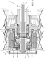
Figure 1 is a schematic longitudinal sectional view of a wheel hub having integrated electric traction given by a wheel according to the invention illustrating first functional elements; -
Figure 2 is a schematic longitudinal sectional view of a wheel hub having integrated electric traction given by a wheel rim according to the invention illustrating second functional elements and the torque lines transmitted during the operation of the wheel hub according to the invention; -
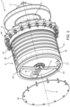
Figure 3 is a partially exploded perspective view of the wheel hub offigures 1 and2 ; -
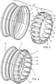
Figure 4 is a perspective view of a wheel for a wheel hub having integrated electric traction according to the invention; -
Figure 5 is an exploded perspective view of the wheel offigure 4 ; -
Figure 6 is a front view of the wheel offigure 4 ; -
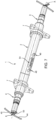
Figure 7 is a perspective view of an axle given by wheel for a wheel hub having integrated electric traction according to the invention. - In
figure 7 , an axle of a vehicle, preferably a heavy vehicle, for example a truck and not illustrated, comprising essentially acentral portion 2 and a pair ofend portions central portion 2, preferably rigidly, along a longitudinal axis A thereof, is referred to with thenumber 1. - The
central portion 2 is advantageously hollow so as to define aspace 5 suitable for housing functional elements of the vehicle as described below. Preferably, theend portions continuous space 5 along the entire extension of theaxle 1 along the axis A. - The
end portions openings 6 configured to allow access to thespace 5 as described below. - Preferably, the
axle 1 comprises at least oneflange 7 arranged near each of theend portions central portion 2 and configured to support operating elements of the vehicle, such as mechanical brakes or sensor means. - The
axle 1 comprises a pair ofwheel hubs 10 comprising afixed portion 8 rigidly carried by therespective end portion movable portion 9 rotationally carried in a free manner by therespective end portion - With regard to the
wheel hubs 10, reference will be made to only one of them for the sake of simplicity, for example the left one, and the considerations below also apply in the same manner to the right wheel hub, of course, as the structure described herein is mirrored with respect to a longitudinal plane of the vehicle. - The
fixed portion 8 is advantageously cup-shaped and comprises aradial wall 8' connected to theend portion 4 and extending perpendicularly to the longitudinal axis A and acylindrical wall 8" extending starting from theradial wall 8' towards the vehicle, viz., towards theintermediate portion 2 of theaxle 1. - The
radial wall 8' is advantageously connected to theend portion 4 by means of a rigid connection, such as an interference fit connection. Preferably, the radial wall is 8' made in a single piece with thecylindrical wall 8''. - The
cylindrical wall 8'' is supported, on the opposite side of theradial wall 8' with respect to themovable portion 9, in a rotationally free manner by supportingmeans 11 such as rolling bearings. In the described embodiment, thecylindrical wall 8'' cooperates with the supportingmeans 11 by means of a supportingelement 12 rigidly connected to thecylindrical wall 8'' and extending radially towards the aforesaid supportingmeans 11. - Preferably the
cylindrical wall 8'' cooperates as described above with themovable portion 9 sealingly by sealing means 13, such as rotating sealing rings, so as to delimit aspace 14 isolated from the external environment radially delimited around the axis A by thecylindrical wall 8'' and axially delimited by theradial wall 8' and by themovable portion 9. - The
wheel hub 10 comprises, housed in thespace 14, anelectric machine 15 provided with a stator 15' and arotor 15" operatively driven by the stator 15'' and atransmission 16 operatively connecting therotor 15" to themovable portion 9 so as to vary the transmitted speed/torque thereof with respect to that originally provided to therotor 15". - In particular, the stator 15' is rigidly carried by the
fixed portion 8, in particular by thecylindrical wall 8'' and therefore extends along the axis A within thespace 14. - The
transmission 16 is advantageously sized so as to be housed radially within the rotor 15'' and particularly also axially comprised by the rotor 15''. - In more detail, the rotor 15'' is connected to a
rotor support 17 carried in a rotationally free manner with respect to the fixedportion 8, in particular with respect to theradial wall 8', viz., to a flanged portion extending with respect thereto. - The
rotor support 17 extends radially within therotor 15 and substantially has the shape of an annular disc housed around theend portion 4. Therotor support 17 is operatively connected by means of thetransmission 16 to themovable portion 9. - In detail, the
transmission 16 comprises a gear, advantageously a differential gear. - In more detail, the
transmission 16 comprises a firstconical gear wheel 21 rigidly connected to therotor support 17 and rotationally free with respect to theend 4, a secondconical gear wheel 22 rigidly carried by theend 4 and a plurality ofplanetary gears 23 operatively cooperating with the first and the secondconical gear wheels - The
planetary gears 23 can be in various number and are supported in a rotationally free manner with respect to the plane of axis B perpendicular to the axis A by means ofrespective pins 24. Merely by way of example, there are fourplanetary gears 23 supported byrespective pins 24 arranged in a cross therebetween. - Each
pin 23 is rigidly carried by aplanetary carrier 25 rigidly connected to themovable portion 9. - The
transmission 16 is provided with sealing means 13, for example carried between thefirst gear wheel 21 and theend 4 further configured to isolate thespace 14. - Thereby, the
space 14 can be supplied with lubricating fluid, such as oil, by means of anozzle 26, for example, carried by the rotatingportion 9 so as to lubricate thetransmission 16. - The
movable portion 9, as mentioned above, is supported in a rotationally free manner by supportingmeans 12, such as rolling bearings, on theend 4. In the embodiment described, it comprises a main movable portion 9' and an auxiliarymovable portion 9" rigidly connected to each other. - Advantageously, the main movable portion 9' essentially comprises a
main portion 9a, preferably an annular disc, cooperating with theaforesaid supporting means 12 and a first flangedportion 9b extending cantilevered axially along the axis A with respect to themain portion 9a and rigidly connected to theplanetary carrier 25. Consequently, the first flangedportion 9b extends radially within therotor 15". - Advantageously, the main movable portion 9' comprises a second flanged
portion 9c extending radially from themain portion 9a and rigidly connected to awheel 30 as described in detail below. - The auxiliary movable portion 9'' extends on the opposite side of the
fixed portion 8 and is configured to provide support for operating elements of the vehicle, such as sensors or other elements which must be integral with themovable portion 9. - The
wheel hub 10 further comprises aconditioning system 40 configured to cool thefixed portion 8, viz., the stator 15' connected thereto. Advantageously, theconditioning system 40 is a fluidised conditioning system. - As can be seen in
figures 1 to 3 , theconditioning system 40 comprises a plurality ofconduits 41 in which a conditioning fluid flows and adjacent to the stator 15' . Advantageously,such conduits 41 are integrated in thefixed portion 8, viz., in thecylindrical portion 8". - Advantageously,
such conduits 41 are made asgrooves 42 defined radially recessed with respect to the surface opposite thespace 14 of thecylindrical portion 8" and isolated from the external environment by means of alid 43 rigidly carried on the cylindrical portion, sealingly, so as to delimitsuch conduits 41. - The
conduits 41 are fluidically connected to adelivery conduit 44 and areturn conduit 45 configured to supply the low-temperature conditioning fluid and collect the high-temperature conditioning fluid once it has flowed in theconduits 41 to cool the fixedportion 8. - As better illustrated in
figure 3 , theconduits 41 are essentially circumferential around the axis A and advantageously with a quadrangular section. In particular, they are equal in size to each other and equally spaced along the axis A. - Advantageously, the
conduits 41 are fluidically connected to thedelivery conduit 44 and thereturn conduit 45 by means ofrespective manifolds 46 advantageously integrated in thefixed portion 8, viz., in thecylindrical portion 8". - Advantageously,
such manifolds 46 are made as asingle groove 47 defined radially recessed with respect to the surface opposite thespace 14 of thecylindrical portion 8'' and isolated from the external environment by means of thesame lid 43 delimiting theconduits 41. In detail, thegroove 47 extends along the axis A for the entire length of thecylindrical portion 8" in which theconduits 41 are made so as to be able to fluidically communicate with each of the latter. - The delivery and return
conduits - Advantageously, the
delivery conduits space 5 and extend between respectivefluidic connectors 48, as visible infigure 7 , configured to allow the connection with further pipes (not illustrated) connecting to the aforesaid heat exchanger of the vehicle. Preferably, thefluidic connectors 48 are made in thecentral portion 2 of theaxle 1. - On the opposite side, the
delivery conduits space 5 by means of theopening 6 and are directed to connect to themanifolds 46 within aspace 51 delimited between the fixedportion 8 and ahead element 52 connected thereto. - Such a
space 51 is therefore radially delimited by the fixedportion 8, in particular by a flange extending between thecylindrical portion 8'' and theradial portion 8' on the opposite side of thecylindrical portion 8'' and axially delimited by thehead element 52 and by theradial portion 8' . - In particular, the
head element 52, in the embodiment illustrated, is rigidly connected to thelid 43. Clearly, it could be made in a single piece therewith in an alternative embodiment. - The
wheel hub 10 further comprisescables 53 for the electrical connection of theelectric machine 15 with electrical energy storage means (not illustrated) such as a battery, of the vehicle. - The
cables 53 are advantageously housed within thespace 5 and extend between respectiveelectrical connectors 54, as visible infigure 7 , configured to allow the connection with further cables (not illustrated) connecting to the aforesaid electrical energy storage means. Preferably, theelectrical connectors 54 are made in thecentral portion 2 of theaxle 1. - On the other side, the
cables 43 exit from thespace 5 by means of theopening 6 in theaforesaid space 51 and pass through a dedicated, sealed opening in thespace 14, towards the stator 15' of theelectric machine 15. - Returning to the
wheel 30, it comprises arim 31 configured to cooperate with a tire of the vehicle and adisc 32 rigidly connected to each other, for example by welding, as is well known. - In particular, the
disc 32 is shaped so as to allow the housing of thewheel hub 10 therein. - In more detail, the
disc 32 comprises a coupling portion 33, advantageously comprising an annular disc and astructural portion 34 configured to provide adequate stiffness to thewheel 30 and allow the connection with therim 31. - In detail, the
structural portion 34 is rigidly connected to a connecting portion 34' thereof which is opposite that connected to the coupling portion 33 to therim 31, viz., to an internal radial surface 31' thereof. - Advantageously, the
structural portion 34 is inclined along the axis A and has a substantially frusto-conical annular disc shape so as to have a larger opening diameter at therim 31 and asmaller opening diameter 35 at the coupling portion 33. - In detail, the
structural portion 34 is inclined between the larger diameter and thesmaller opening diameter 35 by a value between 15° and 25°, in particular 20°. The inclination provided allows to obtain asmaller opening diameter 35 by at least 400 mm. - Preferably, the
structural portion 34 has a corrugated extension, preferably made circumferentially to the axis A. In greater detail, such a corrugated profile comprises a plurality ofgrooves 36 made parallel to the axis A alternated with each other by a plurality ofridges 37. - Preferably, the
grooves 36 are of substantially curved section, advantageously concave facing towards therim 31. In more detail, theridges 37 define a substantially flat surface of constant section between the connecting portion 34' and the coupling portion 33. - Advantageously, both the
grooves 36 and theridges 37 each have an equal shape to one another. Thereby, preferably, they are angularly equidistant around the axis A. - The coupling portion 33 is substantially flat and defines a plurality of
openings 38, advantageously equally spaced circumferentially with respect to the axis A to allow the fixing, for example as illustrated by threaded means, to theflange 9c of themovable portion 9. - The operation of the embodiment of the wheel hub, axle and vehicle according to the invention described above is as follows, referring to the torque lines of
figure 2 . - In a first operating condition, of traction, the stator 15', uses the electrical energy supplied thereto by the
electrical cables 53 to cooperate electromagnetically with the rotor 15'', carrying it into rotation; the latter rotates integrally with therotor support 17, which in turn drags thegear wheel 21. The latter rotates theplanetary carriers 23 which mesh between thegear wheels planetary carrier 25 into rotation by means of thepins 24. Thereby, theplanetary carrier 25 drags themovable portion 9 to which it is connected, which is directly connected to thewheel 30, which is thus carried into rotation, moving the vehicle. - In a second, regenerative operating condition, the
wheel 30 carries themovable portion 9 into rotation, which carries theplanetary carrier 25 into rotation, which drags theplanetary carriers 23 by means of thepins 24, which meshing between thewheels rotor support 17 into rotation. The latter then rotates the rotor 15'', which, by interacting electromagnetically with the stator 15', generates electricity which will be stored by means of theelectrical cables 53 in the energy storage means of the vehicle. - From the above, the advantages of a wheel, a wheel hub, axle and vehicle according to the invention are clear.
- The use of a wheel as illustrated allows the wheel hub to be housed internally easily without however compromising the structural properties thereof.
- In fact, the particular inclination of the disc in addition to the corrugated shape allows a high moment of inertia to be obtained, which allows to support the loads acting thereon.
- Further, the manufacture of the disc of the wheel illustrated is particularly inexpensive, as it does not involve the step of punching holes according to the known art.
- It is further possible to provide an axle having integrated electric traction by means of the hub having integrated electric with low sizes and weights.
- In particular, the housing of the electric machine in the wheel hub and the transmission within the free space of the rotor allows to obtain a traction system which is compact, light and isolated from the external environment and therefore protected from wear and the ingress of dirt.
- Furthermore, the integration of the cooling and electrical power supply systems passage inside the axle and the passage of the head space allows an easy and optimised assembly, reducing axle manufacturing time.
- Furthermore, the proposed axle and the proposed wheel hub are modular and scalable as a function of different vehicle types and sizes.
- Finally, it is clear that modifications and variations can be made to the wheel, the wheel hub, axle and vehicle according to the present invention which, however, do not depart from the scope of protection defined by the claims.
- Of course, as mentioned, the shapes of the
axle 1 andwheel hub 10 can have different shapes and be made of several different parts. - Further, the described gear wheels and gears could vary as well as elements not described and of known existence for the assembly of a hub, axle and vehicle according to the present invention could be present.
- Furthermore, although a twin wheel solution is described, the wheel hub can be applied to any type of wheel, even a single one.
Claims (15)
- Wheel (30) for a wheel hub (10) for an axle (1) of a heavy vehicle, said wheel (30) comprising a rim (31) suitable for cooperating with a tire of said vehicle and a disc (32) connected rigidly to said rim (31) and configured to be connected to said wheel hub (10), said disc (32) comprising a coupling portion (33) configured to connect said disc (32) to said wheel hub (10) and a structural portion (34) connecting said rim (31) to said coupling portion (33), wherein said structural portion (34) is inclined along an axis (A) of said wheel (30), said structural portion (34) defining a corrugated profile circumferentially along said axis (A) and being tapered between a connecting portion (34') with said rim (31) and said coupling portion (33), said inclination being between 15° and 25°.
- Wheel according to claim 1, wherein said inclination is 20°.
- Wheel according to claim 1 or 2, wherein said structural portion (34) is substantially a frusto-conical ring.
- Wheel according to claim 1 to 3, wherein said corrugated profile comprises a plurality of grooves (36) extending parallel to said axis (A) alternated with each other by a plurality of ridges (37).
- Wheel according to claim 4, wherein said grooves (36) have the same shape with each other.
- Wheel according to claim 4 or 5, wherein said ridges (37) have the same shape with each other.
- Wheel according to one of claims 4 to 6, wherein said grooves (36) have a curved section.
- Wheel according to claim 7, wherein said curved section is concave towards said rim (31).
- Wheel according to one of claims 4 to 8, wherein said ridges define a flat and substantially constant surface between said connecting portion (34') and said connecting portion (33).
- Wheel according to one of the preceding claims, wherein said connecting portion (33) extends radially with respect to said axis (A).
- Wheel according to one of the preceding claims, wherein said connecting portion (33) has the shape of a ring.
- Wheel according to one of the preceding claims, wherein said connecting portion (33) defines a circular opening, said circular opening being sized to have a diameter greater than 400 mm.
- Wheel hub (10) for an axle (1) of a heavy vehicle, said wheel hub (10) comprising a fixed portion (8) configured to be rigidly carried by one end (3, 4) of said axle (1) and a movable portion (9) configured to be carried in a rotationally free manner by said end (3, 4) of said axle (1) and with respect to said fixed portion (8), said fixed portion (8) and said movable portion (9) delimiting with said end (3, 4) a space (14) isolated from the external environment, said wheel hub (10) comprising an electric machine (15) housed in said space (14) and comprising a stator (15') carried integral with said fixed portion (8) and a rotor (15') operatively connected to said movable portion (9), said wheel hub (10) comprising a transmission (16) housed in said space (14) radially inside with respect to said rotor (15") and connecting said rotor (15 ") to said movable portion (19) so as to vary the speed/torque between said rotor (15'') and said movable portion (9), said wheel hub (10) comprising a wheel (30) according to one of the preceding claims.
- Axle (1) extending along a longitudinal axis (A) and comprising a central portion (2) and a pair of end portions (3, 4) connected at the ends of said central portion (2) along said axis (A) and respective wheel hubs (10) according to claim 13 each carried by a respective end portion (3, 4).
- Vehicle comprising an axle (1) according to claim 14.
Applications Claiming Priority (1)
| Application Number | Priority Date | Filing Date | Title |
|---|---|---|---|
| IT102023000008427A IT202300008427A1 (en) | 2023-04-28 | 2023-04-28 | IMPROVED RIM FOR INTEGRATED ELECTRIC DRIVE WHEEL HUB |
Publications (3)
| Publication Number | Publication Date |
|---|---|
| EP4454923A1 true EP4454923A1 (en) | 2024-10-30 |
| EP4454923B1 EP4454923B1 (en) | 2025-10-15 |
| EP4454923C0 EP4454923C0 (en) | 2025-10-15 |
Family
ID=88097654
Family Applications (1)
| Application Number | Title | Priority Date | Filing Date |
|---|---|---|---|
| EP24171853.5A Active EP4454923B1 (en) | 2023-04-28 | 2024-04-23 | Improved wheel for a wheel hub having integrated electric traction |
Country Status (2)
| Country | Link |
|---|---|
| EP (1) | EP4454923B1 (en) |
| IT (1) | IT202300008427A1 (en) |
Citations (3)
| Publication number | Priority date | Publication date | Assignee | Title |
|---|---|---|---|---|
| WO2011076009A1 (en) * | 2009-12-25 | 2011-06-30 | 正兴车轮集团有限公司 | Spoke of light-weight wheel for vehicle |
| WO2019020898A1 (en) * | 2017-07-27 | 2019-01-31 | Compagnie Generale Des Etablissements Michelin | Wheel for mouting a tyre-type device for a vehicle |
| CN211138906U (en) * | 2019-12-17 | 2020-07-31 | 正兴车轮集团有限公司 | Lightweight wheel spoke that waist was strengthened |
-
2023
- 2023-04-28 IT IT102023000008427A patent/IT202300008427A1/en unknown
-
2024
- 2024-04-23 EP EP24171853.5A patent/EP4454923B1/en active Active
Patent Citations (3)
| Publication number | Priority date | Publication date | Assignee | Title |
|---|---|---|---|---|
| WO2011076009A1 (en) * | 2009-12-25 | 2011-06-30 | 正兴车轮集团有限公司 | Spoke of light-weight wheel for vehicle |
| WO2019020898A1 (en) * | 2017-07-27 | 2019-01-31 | Compagnie Generale Des Etablissements Michelin | Wheel for mouting a tyre-type device for a vehicle |
| CN211138906U (en) * | 2019-12-17 | 2020-07-31 | 正兴车轮集团有限公司 | Lightweight wheel spoke that waist was strengthened |
Also Published As
| Publication number | Publication date |
|---|---|
| EP4454923B1 (en) | 2025-10-15 |
| IT202300008427A1 (en) | 2024-10-28 |
| EP4454923C0 (en) | 2025-10-15 |
Similar Documents
| Publication | Publication Date | Title |
|---|---|---|
| EP3778281B1 (en) | Electric wheel assembly with integrated hub motor | |
| CN108340768B (en) | Electric wheel assembly of integrated hub motor | |
| US7528518B2 (en) | In-wheel motor | |
| CN111361358B (en) | Heavy-duty electric wheel | |
| EP2666655B1 (en) | In-wheel motor drive device | |
| JP2017047698A (en) | Electric car | |
| US9963029B1 (en) | Hybrid transmission device | |
| US11472226B2 (en) | Lubricant supported electric motor with wheel support | |
| CN108081938A (en) | The dynamical system of the electricity of friction optimization | |
| EP0592603A1 (en) | Direct drive axle brake and cooling system | |
| JP2016114184A (en) | Cycloid speed reducer and in-wheel motor drive with cycloid speed reducer | |
| CN114600343A (en) | Lubricant-supported rotor structure | |
| KR20210136026A (en) | In-wheel drive systems and motor vehicles | |
| JP2023550142A (en) | power transmission device | |
| KR102622464B1 (en) | Power transmission device | |
| JP7070793B2 (en) | Rotating electric machine | |
| US11841066B2 (en) | Axle assembly having a gear reduction module with multiple gear sets | |
| WO2016002571A1 (en) | In-wheel motor drive device | |
| JP4068697B2 (en) | Driving axle | |
| JP7425229B2 (en) | modular hybrid transmission | |
| WO2022137862A1 (en) | This semiconductor device comprises: a semiconductor layer having a main surface; a first conductive-type well region formed on a surface layer portion of the main surface of the semiconductor layer; a first conductive-type first impurity region formed on a surface layer portion of the well region and having an inner wall portion; and a second conductive-type annular second impurity region formed on the surface layer portion of the well region inside the inner wall part so as to form a pn junction with the well region. | |
| EP4454923B1 (en) | Improved wheel for a wheel hub having integrated electric traction | |
| CN105313666A (en) | Drivetrain for a ground vehicle | |
| EP3829914B1 (en) | A lubricant supported electric motor with bearing support | |
| EP4454919B1 (en) | Improved electric traction wheel hub |
Legal Events
| Date | Code | Title | Description |
|---|---|---|---|
| PUAI | Public reference made under article 153(3) epc to a published international application that has entered the european phase |
Free format text: ORIGINAL CODE: 0009012 |
|
| STAA | Information on the status of an ep patent application or granted ep patent |
Free format text: STATUS: THE APPLICATION HAS BEEN PUBLISHED |
|
| AK | Designated contracting states |
Kind code of ref document: A1 Designated state(s): AL AT BE BG CH CY CZ DE DK EE ES FI FR GB GR HR HU IE IS IT LI LT LU LV MC ME MK MT NL NO PL PT RO RS SE SI SK SM TR |
|
| STAA | Information on the status of an ep patent application or granted ep patent |
Free format text: STATUS: REQUEST FOR EXAMINATION WAS MADE |
|
| 17P | Request for examination filed |
Effective date: 20250401 |
|
| GRAP | Despatch of communication of intention to grant a patent |
Free format text: ORIGINAL CODE: EPIDOSNIGR1 |
|
| STAA | Information on the status of an ep patent application or granted ep patent |
Free format text: STATUS: GRANT OF PATENT IS INTENDED |
|
| INTG | Intention to grant announced |
Effective date: 20250509 |
|
| GRAS | Grant fee paid |
Free format text: ORIGINAL CODE: EPIDOSNIGR3 |
|
| GRAA | (expected) grant |
Free format text: ORIGINAL CODE: 0009210 |
|
| STAA | Information on the status of an ep patent application or granted ep patent |
Free format text: STATUS: THE PATENT HAS BEEN GRANTED |
|
| AK | Designated contracting states |
Kind code of ref document: B1 Designated state(s): AL AT BE BG CH CY CZ DE DK EE ES FI FR GB GR HR HU IE IS IT LI LT LU LV MC ME MK MT NL NO PL PT RO RS SE SI SK SM TR |
|
| REG | Reference to a national code |
Ref country code: GB Ref legal event code: FG4D Ref country code: CH Ref legal event code: F10 Free format text: ST27 STATUS EVENT CODE: U-0-0-F10-F00 (AS PROVIDED BY THE NATIONAL OFFICE) Effective date: 20251015 |
|
| REG | Reference to a national code |
Ref country code: IE Ref legal event code: FG4D |
|
| U01 | Request for unitary effect filed |
Effective date: 20251017 |
|
| U07 | Unitary effect registered |
Designated state(s): AT BE BG DE DK EE FI FR IT LT LU LV MT NL PT RO SE SI Effective date: 20251023 |
|
| U20 | Renewal fee for the european patent with unitary effect paid |
Year of fee payment: 3 Effective date: 20260305 |
|
| PG25 | Lapsed in a contracting state [announced via postgrant information from national office to epo] |
Ref country code: ES Free format text: LAPSE BECAUSE OF FAILURE TO SUBMIT A TRANSLATION OF THE DESCRIPTION OR TO PAY THE FEE WITHIN THE PRESCRIBED TIME-LIMIT Effective date: 20251015 |
|
| PG25 | Lapsed in a contracting state [announced via postgrant information from national office to epo] |
Ref country code: NO Free format text: LAPSE BECAUSE OF FAILURE TO SUBMIT A TRANSLATION OF THE DESCRIPTION OR TO PAY THE FEE WITHIN THE PRESCRIBED TIME-LIMIT Effective date: 20260115 |
|
| PG25 | Lapsed in a contracting state [announced via postgrant information from national office to epo] |
Ref country code: HR Free format text: LAPSE BECAUSE OF FAILURE TO SUBMIT A TRANSLATION OF THE DESCRIPTION OR TO PAY THE FEE WITHIN THE PRESCRIBED TIME-LIMIT Effective date: 20251015 |
|
| PG25 | Lapsed in a contracting state [announced via postgrant information from national office to epo] |
Ref country code: RS Free format text: LAPSE BECAUSE OF FAILURE TO SUBMIT A TRANSLATION OF THE DESCRIPTION OR TO PAY THE FEE WITHIN THE PRESCRIBED TIME-LIMIT Effective date: 20260115 |
|
| PG25 | Lapsed in a contracting state [announced via postgrant information from national office to epo] |
Ref country code: IS Free format text: LAPSE BECAUSE OF FAILURE TO SUBMIT A TRANSLATION OF THE DESCRIPTION OR TO PAY THE FEE WITHIN THE PRESCRIBED TIME-LIMIT Effective date: 20260215 |
|
| PG25 | Lapsed in a contracting state [announced via postgrant information from national office to epo] |
Ref country code: PL Free format text: LAPSE BECAUSE OF FAILURE TO SUBMIT A TRANSLATION OF THE DESCRIPTION OR TO PAY THE FEE WITHIN THE PRESCRIBED TIME-LIMIT Effective date: 20251015 |