EP4454911A1 - Hemming structure and vehicle - Google Patents
Hemming structure and vehicle Download PDFInfo
- Publication number
- EP4454911A1 EP4454911A1 EP23766024.6A EP23766024A EP4454911A1 EP 4454911 A1 EP4454911 A1 EP 4454911A1 EP 23766024 A EP23766024 A EP 23766024A EP 4454911 A1 EP4454911 A1 EP 4454911A1
- Authority
- EP
- European Patent Office
- Prior art keywords
- buckle
- assembling hole
- main body
- engaging cavity
- wall
- Prior art date
- Legal status (The legal status is an assumption and is not a legal conclusion. Google has not performed a legal analysis and makes no representation as to the accuracy of the status listed.)
- Pending
Links
Images



Classifications
-
- B—PERFORMING OPERATIONS; TRANSPORTING
- B60—VEHICLES IN GENERAL
- B60J—WINDOWS, WINDSCREENS, NON-FIXED ROOFS, DOORS, OR SIMILAR DEVICES FOR VEHICLES; REMOVABLE EXTERNAL PROTECTIVE COVERINGS SPECIALLY ADAPTED FOR VEHICLES
- B60J10/00—Sealing arrangements
- B60J10/70—Sealing arrangements specially adapted for windows or windscreens
-
- B—PERFORMING OPERATIONS; TRANSPORTING
- B60—VEHICLES IN GENERAL
- B60J—WINDOWS, WINDSCREENS, NON-FIXED ROOFS, DOORS, OR SIMILAR DEVICES FOR VEHICLES; REMOVABLE EXTERNAL PROTECTIVE COVERINGS SPECIALLY ADAPTED FOR VEHICLES
- B60J10/00—Sealing arrangements
- B60J10/30—Sealing arrangements characterised by the fastening means
- B60J10/36—Sealing arrangements characterised by the fastening means using separately inserted fastening means, e.g. using clips, beads or strips
-
- B—PERFORMING OPERATIONS; TRANSPORTING
- B60—VEHICLES IN GENERAL
- B60J—WINDOWS, WINDSCREENS, NON-FIXED ROOFS, DOORS, OR SIMILAR DEVICES FOR VEHICLES; REMOVABLE EXTERNAL PROTECTIVE COVERINGS SPECIALLY ADAPTED FOR VEHICLES
- B60J10/00—Sealing arrangements
- B60J10/20—Sealing arrangements characterised by the shape
- B60J10/26—Sealing arrangements characterised by the shape characterised by the surface shape
- B60J10/265—Sealing arrangements characterised by the shape characterised by the surface shape the surface being primarily decorative
-
- B—PERFORMING OPERATIONS; TRANSPORTING
- B60—VEHICLES IN GENERAL
- B60J—WINDOWS, WINDSCREENS, NON-FIXED ROOFS, DOORS, OR SIMILAR DEVICES FOR VEHICLES; REMOVABLE EXTERNAL PROTECTIVE COVERINGS SPECIALLY ADAPTED FOR VEHICLES
- B60J10/00—Sealing arrangements
- B60J10/30—Sealing arrangements characterised by the fastening means
-
- B—PERFORMING OPERATIONS; TRANSPORTING
- B60—VEHICLES IN GENERAL
- B60R—VEHICLES, VEHICLE FITTINGS, OR VEHICLE PARTS, NOT OTHERWISE PROVIDED FOR
- B60R13/00—Elements for body-finishing, identifying, or decorating; Arrangements or adaptations for advertising purposes
- B60R13/04—External Ornamental or guard strips; Ornamental inscriptive devices thereon
-
- B—PERFORMING OPERATIONS; TRANSPORTING
- B60—VEHICLES IN GENERAL
- B60R—VEHICLES, VEHICLE FITTINGS, OR VEHICLE PARTS, NOT OTHERWISE PROVIDED FOR
- B60R13/00—Elements for body-finishing, identifying, or decorating; Arrangements or adaptations for advertising purposes
- B60R13/06—Sealing strips
-
- F—MECHANICAL ENGINEERING; LIGHTING; HEATING; WEAPONS; BLASTING
- F16—ENGINEERING ELEMENTS AND UNITS; GENERAL MEASURES FOR PRODUCING AND MAINTAINING EFFECTIVE FUNCTIONING OF MACHINES OR INSTALLATIONS; THERMAL INSULATION IN GENERAL
- F16B—DEVICES FOR FASTENING OR SECURING CONSTRUCTIONAL ELEMENTS OR MACHINE PARTS TOGETHER, e.g. NAILS, BOLTS, CIRCLIPS, CLAMPS, CLIPS OR WEDGES; JOINTS OR JOINTING
- F16B21/00—Means for preventing relative axial movement of a pin, spigot, shaft or the like and a member surrounding it; Stud-and-socket releasable fastenings
- F16B21/06—Releasable fastening devices with snap-action
- F16B21/08—Releasable fastening devices with snap-action in which the stud, pin, or spigot has a resilient part
-
- F—MECHANICAL ENGINEERING; LIGHTING; HEATING; WEAPONS; BLASTING
- F16—ENGINEERING ELEMENTS AND UNITS; GENERAL MEASURES FOR PRODUCING AND MAINTAINING EFFECTIVE FUNCTIONING OF MACHINES OR INSTALLATIONS; THERMAL INSULATION IN GENERAL
- F16B—DEVICES FOR FASTENING OR SECURING CONSTRUCTIONAL ELEMENTS OR MACHINE PARTS TOGETHER, e.g. NAILS, BOLTS, CIRCLIPS, CLAMPS, CLIPS OR WEDGES; JOINTS OR JOINTING
- F16B21/00—Means for preventing relative axial movement of a pin, spigot, shaft or the like and a member surrounding it; Stud-and-socket releasable fastenings
- F16B21/06—Releasable fastening devices with snap-action
- F16B21/08—Releasable fastening devices with snap-action in which the stud, pin, or spigot has a resilient part
- F16B21/086—Releasable fastening devices with snap-action in which the stud, pin, or spigot has a resilient part the shank of the stud, pin or spigot having elevations, ribs, fins or prongs intended for deformation or tilting predominantly in a direction perpendicular to the direction of insertion
-
- F—MECHANICAL ENGINEERING; LIGHTING; HEATING; WEAPONS; BLASTING
- F16—ENGINEERING ELEMENTS AND UNITS; GENERAL MEASURES FOR PRODUCING AND MAINTAINING EFFECTIVE FUNCTIONING OF MACHINES OR INSTALLATIONS; THERMAL INSULATION IN GENERAL
- F16B—DEVICES FOR FASTENING OR SECURING CONSTRUCTIONAL ELEMENTS OR MACHINE PARTS TOGETHER, e.g. NAILS, BOLTS, CIRCLIPS, CLAMPS, CLIPS OR WEDGES; JOINTS OR JOINTING
- F16B5/00—Joining sheets or plates, e.g. panels, to one another or to strips or bars parallel to them
- F16B5/12—Fastening strips or bars to sheets or plates, e.g. rubber strips, decorative strips for motor vehicles, by means of clips
- F16B5/128—Fastening strips or bars to sheets or plates, e.g. rubber strips, decorative strips for motor vehicles, by means of clips a strip with a C-or U-shaped cross section being fastened to a plate such that the fastening means remain invisible, e.g. the fastening being completely enclosed by the strip
Definitions
- the present disclosure relates to the field of encapsulation assembly technologies, and in particular, to an encapsulation structure and a vehicle.
- the decorative members are generally installed on encapsulation materials of automobile windows to serve as decoration and sealing. Generally, the decorative members are installed in such a manner that they are difficult to disassemble and replace. If the decorative members can be disassembled directly from the outside, it may lead to poor anti-theft properties.
- an encapsulation structure and a vehicle are provided that are easy to disassemble and assemble and have a good anti-theft performance.
- An encapsulation structure includes:
- the buckle includes at least two elastic buckling bodies, all of the elastic buckling bodies are provided with the limiting protrusion, two different elastic buckling bodies are spaced apart, when the buckle is in the squeezed state, the elastic buckling bodies are elastically deformed, and a distance between the limiting protrusions on the two different elastic buckling bodies decreases, and when the limiting protrusions enter the engaging cavity from the first assembling hole, the elastic buckling bodies are reset, the buckle switches from the squeezed state to the recovered state, and the distance between the limiting protrusions on the two different elastic buckling bodies increases.
- an end face of an end of the active member configured to extend into the engaging cavity is provided with a groove, the active member moves in a direction close to or away from the buckle, a side of the limiting protrusion close to the active member is a first contact surface, the first contact surface is an inclined surface or an arc surface, and when the active member moves in the direction close to the buckle, different limiting protrusions respectively extend into the groove, a groove wall of the groove contacts the first contact surface and exerts a force on the limiting protrusions, so that the limiting protrusions are squeezed, the buckle switches from the recovered state to the squeezed state, and the distance between the limiting protrusions on the two different elastic buckling bodies decreases.
- a side of the limiting protrusion away from the active member is a second contact surface
- the second contact surface is an inclined surface or an arc surface
- a distance between the second contact surface and the elastic buckling bodies gradually decreases in a direction away from the active member
- a side of the main body away from the first assembling hole is provided with a second assembling hole in communication with the engaging cavity
- the active member is rotatably provided in the second assembling hole
- the end of the active member configured to extend into the engaging cavity is a push end
- the push end being externally provided with a flange surrounding a position of the push end
- the inner wall of the engaging cavity includes a first wall and a second wall arranged oppositely, a communication point between the first assembling hole and the engaging cavity is located on the first wall, a communication point between the second assembling hole and the engaging wall is located on the second wall
- the inner wall of the engaging cavity is provided with a stop protrusion, a distance between the stop protrusion and the second wall is greater than a thickness of the flange, and the flange is provided with a notch allowing the stop protrusion to pass through.
- the first contact surface abuts against the groove wall of the groove.
- an inner diameter of the groove is less than or equal to a diameter of the first assembling hole.
- the encapsulation structure further includes a first sealing member and a second sealing member, the first sealing member being arranged between the decorative member and the main body, the first sealing member being arranged around the buckle, the second sealing member being arranged on the side of the main body away from the decorative member, and the second sealing member being arranged around the active member.
- the main body includes an encapsulation, a glass plate, and a reinforcing member
- the encapsulation is connected to an edge of the glass plate and the reinforcing member respectively
- the reinforcing member and the decorative member are located on two sides of the encapsulation respectively
- the engaging cavity and the first assembling hole are both arranged on the reinforcing member
- the encapsulation is provided with an avoiding hole arranged corresponding to the first assembling hole
- the buckle passes through the avoiding hole and the first assembling hole sequentially and extends into the engaging cavity.
- a vehicle includes the encapsulation structure as described in any one of the above embodiments.
- an embodiment discloses an encapsulation structure (not labeled), including a main body 100, a decorative member 200, and an active member 300.
- the main body 100 is provided with an engaging cavity 101 therein.
- the main body 100 is provided with a first assembling hole 102 in communication with the engaging cavity 101.
- the decorative member 200 is provided with a buckle 210.
- An outer side of the buckle 210 is provided with a limiting protrusion 220.
- the buckle 210 has a squeezed state and a recovered state. When the buckle 210 is squeezed to enable the buckle 210 to switch from the recovered state to the squeezed state, the limiting protrusion 220 can pass through the first assembling hole 102.
- the active member 300 is provided on the side of the main body 100 away from the decorative member 200.
- the active member 300 is movably matched with the main body 100 and at least partially extends into the engaging cavity 101.
- the active member 300 can move relative to the main body 100 and squeezes the buckle 210, so that the buckle 210 switches from the recovered state to the squeezed state.
- the buckle 210 on the decorative member 200 can be squeezed to enable the buckle 210 to switch from the recovered state to the squeezed state.
- the buckle 210 may enter the engaging cavity 101 through the first assembling hole 102.
- the buckle 210 can switch from the squeezed state to the recovered state.
- the limiting protrusion 220 on the buckle 210 can abut against the inner wall of the engaging cavity 101, so as to prevent the buckle 210 from passing through the first assembling hole 102 in a direction away from the engaging cavity 101, thus achieving engaging and assembling of the decorative member 200 and the main body 100.
- the active member 300 can be moved to enable the active member 300 to move in the engaging cavity 101 relative to the main body 100.
- the active member 300 can squeeze the buckle 210 to enable the buckle 210 to switch from the recovered state to the squeezed state again.
- the buckle 210 can pass through the first assembling hole 102 again and be disengaged from the engaging cavity 101.
- the decorative member 200 and the main body 100 are detachably matched, and the decorative member 200 can be replaced.
- disassembly and assembly can be realized by moving the active member 300, making the disassembly and assembly easier.
- the decorative member 200 is generally arranged outwards, the active member 300 is located on a side of the main body 100 away from the decorative member 200, such that the decorative member 200 cannot be directly disassembled from the side where the decorative member 200 is located relative to the main body 100, therefore an anti-theft effect is improved in use.
- part of the buckle 210 is located in the engaging cavity 101.
- the buckle 210 cannot be directly squeezed, and it is required to squeeze the buckle 210 by moving the active member 300. That is, after the decorative member 200 is engaged with the main body 100, the operation of separating the decorative member 200 from the main body 100 can only be performed through the active member 300, which can prevent separation of the decorative member 200 from the main body 100 caused by squeezing of the buckle 210 in the case of positional interference or the like, so that structural stability is improved after the decorative member 200 is engaged with the main body 100.
- a force may be exerted on the buckle 210 to squeeze the buckle 210.
- the maximum size of the buckle 210 is reduced, and the buckle 210 can enter the first assembling hole 102.
- an outer wall of the buckle 210 may abut against a hole wall of the first assembling hole 102.
- the limiting protrusion 220 on the buckle 210 abuts against the hole wall of the first assembling hole 102.
- the buckle 210 is still in the squeezed state.
- the buckle 210 may switch from the squeezed state to the recovered state, the limiting protrusion 220 is displaced to some extent and can abut against the inner wall of the engaging cavity 101.
- An overall size of the buckle 210 is increased, which can prevent the buckle 210 from separating the first assembling hole 102, thus achieving the engagement between the decorative member 200 and the main body 100.
- a size of the engaging cavity 101 is greater than a diameter of the first assembling hole 102, such that during the entry of the limiting protrusion 220 into the engaging cavity 101 through the first assembling hole 102, the limiting protrusion 220 is displaced by a certain distance along a radial direction of the first assembling hole 102, such that the buckle 210 can switch from the squeezed state to the recovered state.
- the limiting protrusion 220 enters the engaging cavity 101 and the buckle 210 switches to the recovered state, the limiting protrusion 220 and the buckle 210 are still squeezed to some extent. However, the buckle 210 cannot pass through the first assembling hole 102 at this time.
- the buckle 210 includes at least two elastic buckling bodies 211, and all of the elastic buckling bodies 211 are provided with the limiting protrusion 220. Two different elastic buckling bodies 211 are spaced apart. When the buckle 210 is in the squeezed state, the elastic buckling bodies 211 are elastically deformed, and a distance between the limiting protrusions 220 on the two different elastic buckling bodies 211 decreases.
- the elastic buckling bodies 211 may be reset, so that the limiting protrusion 220 undergoes a certain displacement from the state of abutting against the hole wall of the first assembling hole 102, and the distance between the limiting protrusions 220 on the two different elastic buckling bodies 211 increases, which can be engaged in the engaging cavity 101, thereby preventing the buckle 210 from detaching the first assembling hole 102, thus making the engagement between the decorative member 200 and the main body 100 more stable.
- two elastic buckling bodies 211 are provided, and the two elastic buckling bodies 211 are spaced apart.
- a plurality of elastic buckling bodies 211 may be provided, all of the elastic buckling bodies 211 are spaced apart along a circumferential direction.
- An avoiding space is formed between all of the elastic buckling bodies 211, and the limiting protrusion 220 is provided on a side of the elastic buckling bodies 211 away from the avoiding space.
- the buckle 210 may include two supports, all of the supports are provided with the above limiting protrusion 220. At least one of the supports is movably matched with the decorative member 200, so that a distance between two supports is adjustable.
- the two supports are provided with a spring.
- the buckle 210 is squeezed, the supports are squeezed, the distance between the two supports may be shortened, and the spring is squeezed. At this time, the buckle 210 is in the squeezed state and can pass through the first assembling hole 102.
- the limiting protrusion 220 enters the engaging cavity 101, the limiting protrusion 220 no longer abuts against the hole wall of the first assembling hole 102.
- a resetting effect of the spring may increase the distance between the limiting protrusions 220 on the two supports, so that the buckle 210 switches to the recovered state and cannot pass through the first assembling hole 102.
- the buckle 210 is an elastic member.
- the buckle 210 When the buckle 210 is squeezed and elastically deformed, the buckle 210 switches to the squeezed state. At this time, the limiting protrusion 220 on the buckle 210 may be displaced, the maximum outer diameter of the buckle 210 is reduced, and the buckle can pass through the first assembling hole 102.
- the buckle 210 When the buckle 210 enters the engaging cavity 101, the buckle 210 is recovered. At this time, the limiting protrusion 220 may be engaged in the engaging cavity 101, causing the maximum outer diameter of the buckle 210 to increase. As a result, the buckle 210 cannot pass through the first assembling hole 102 to realize the engagement between the decorative member 200 and the main body 100.
- an end face of an end of the active member 300 configured to extend into the engaging cavity 101 is provided with a groove 301.
- the active member 300 moves in a direction close to or away from the buckle 210.
- a side of the limiting protrusion 220 close to the active member 300 is a first contact surface 221, and the first contact surface 221 is an inclined surface or an arc surface.
- different limiting protrusions 220 respectively extend into the groove 301.
- a groove wall of the groove 301 contacts the first contact surface 221 and exerts a force on the limiting protrusions 220, so that the limiting protrusions 220 are squeezed, the buckle 210 switches from the recovered state to the squeezed state, and the distance between the limiting protrusions 220 on the two different elastic buckling bodies 211 decreases.
- the active member 300 by pushing the active member 300, the active member 300 is close to the buckle 210 in the engaging cavity 101, and the buckle 210 may extend into the groove 301 of the active member 300.
- the groove wall of the groove 301 may exert a force on the first contact surface 221, causing the limiting protrusion 220 to be stressed and causing the buckle 210 to be squeezed.
- the buckle 210 switches from the recovered state to the squeezed state, a distance between the limiting protrusions 220 on two different elastic buckling bodies 211 decreases, and the buckle 210 may pass through the first assembling hole 102 again, which may realize separation of the decorative member 200 from the main body 100 and is easy to operate.
- an end of the groove wall of the groove 301 close to the buckle 210 is a tapered surface, and an inner diameter of the tapered surface gradually increases in a direction close to the buckle 210, which can better match the shape of the first contact surface 221, increase a contact area, and reduce damage to the first contact surface 221.
- the number of the active member 300 corresponds to the number of the elastic buckling body 211.
- the number of the active member 300 is also two.
- One active member 300 moves relative to the main body 100 and can abut against one elastic buckling body 211, so as to squeeze the elastic buckling body 211 and move the elastic buckling body 211 close to another elastic buckling body 211.
- two active members 300 may be moved simultaneously, so that the two active members 300 squeeze two elastic buckling bodies 211 respectively to cause the two elastic buckling bodies 211 to be close to each other, thereby reducing a distance between the limiting protrusions 220 on the two elastic buckling bodies 211.
- the buckle 210 switches from the recovered state to the squeezed state and can pass through the first assembling hole 102 again.
- a side of the limiting protrusion 220 away from the active member 300 is a second contact surface 222
- the second contact surface 222 is an inclined surface or an arc surface
- a distance between the second contact surface 222 and the elastic buckling bodies 211 gradually decreases in a direction away from the active member 300.
- the second contact surface 222 can facilitate the buckle 210 to smoothly enter the first assembling hole 102 when the active member 300 squeezes the elastic buckling body 211.
- the contact between the limiting protrusion 220 and the main body 100 may cause the limiting protrusion 220 to be subjected to a force in a direction from the first assembling hole 102 to the engaging cavity 101, so that the decorative member 200 and the main body 100 are engaged.
- the limiting protrusion 220 is partially located in the engaging cavity 101, so that the second contact surface 222 is in contact with a junction between the hole wall of the first assembling hole 102 and the inner wall of the engaging cavity 101.
- the buckle 210 is subjected to a force in the direction from the first assembling hole 102 to the engaging cavity 101, so that the decorative member 200 and the main body 100 are engaged.
- the side of the main body 100 away from the first assembling hole 102 is provided with a second assembling hole (not labeled) in communication with the engaging cavity 101, and the active member 300 is rotatably provided in the second assembling hole.
- the end of the active member 300 configured to extend into the engaging cavity 101 is a push end (not labeled), the push end is externally provided with a flange 310 surrounding the position of the push end.
- the inner wall of the engaging cavity 101 includes a first wall (not labeled) and a second wall (not labeled) arranged oppositely.
- a communication point between the first assembling hole 102 and the engaging cavity 101 is located on the first wall, a communication point between the second assembling hole and the engaging wall is located on the second wall.
- the inner wall of the engaging cavity 101 is provided with a stop protrusion 110, a distance between the stop protrusion 110 and the second wall is greater than a thickness of the flange 310, and the flange 310 is provided with a notch 311 allowing the stop protrusion 110 to pass through.
- the active member 300 may be rotated, so that the notch 311 on the flange 310 of the active member 300 rotates to a position corresponding to the stop protrusion 110.
- the active member 300 may move towards the buckle 210 through the stop protrusion 110 to squeeze the buckle 210.
- the active member 300 may be moved, so that the flange 310 of the active member 300 is located between the stop protrusion 110 and the second wall, and the active member 300 is rotated to stagger the stop protrusion 110 from the notch 311.
- the active member 300 is limited between the limiting protrusion 220 and the second wall and may not move freely. Therefore, separation of the decorative member 200 from the main body 100 due to squeezing of the buckle 210 caused by an accidental touch on the active member 300 can be prevented, ensuring stability of the engagement between the decorative member 200 and the main body 100.
- the first contact surface 221 abuts against the groove wall of the groove 301.
- the first contact surface 221 abuts against the groove wall of the groove 301 of the active member 300, thus enabling the active member 300 and the buckle 210 to exert forces on each other.
- the active member 300 and the buckle 210 are fixed in the engaging cavity 101. In the above encapsulation structure, the active member 300 and the buckle 210 are not prone to displace relative to each other in a vibrating environment, which can reduce noise or abnormal noise.
- an inner diameter of the groove 301 is less than or equal to a diameter of the first assembling hole 102.
- the inner diameter of the groove 301 is less than the diameter of the first assembling hole 102.
- the encapsulation structure further includes a first sealing member 400 and a second sealing member 500.
- the first sealing member 400 is arranged between the decorative member 200 and the main body 100, and the first sealing member 400 is arranged around the buckle 210.
- the second sealing member 500 is arranged on the side of the main body 100 away from the decorative member 200, and the second sealing member 500 is arranged around the active member 300.
- the first sealing member 400 and the second sealing member 500 are foam gaskets, which have good sealing effects and have certain buffering and shock-absorbing effects.
- the main body 100 includes an encapsulation 120, a glass plate 130, and a reinforcing member 140.
- the encapsulation 120 is connected to an edge of the glass plate 130 and the reinforcing member 140, respectively.
- the reinforcing member 140 and the decorative member 200 are located on two sides of the encapsulation 120 respectively.
- the engaging cavity 101 and the first assembling hole 102 are both arranged on the reinforcing member 140.
- the encapsulation 120 is provided with an avoiding hole 121 arranged corresponding to the first assembling hole 102, and the buckle 210 passes through the avoiding hole 121 and the first assembling hole 102 sequentially and extends into the engaging cavity 101.
- the encapsulation 120 is located at the edge of the glass plate 130 and is connected to the glass plate 130.
- the reinforcing member 140 can provide structural support for the encapsulation 120.
- the decorative member 200 is located on the side of the encapsulation 120 away from the reinforcing member 140 and plays a decorative role.
- the decorative member 200 is in the shape of a strip, and the encapsulation 120 is provided with placement grooves that match edges on two sides of the decorative member 200 to limit the decorative member 200 and guide an installation position.
- the glass plate 130 may be made of tempered glass, laminated glass, semi-tempered laminated glass, or other glass materials.
- the encapsulation 120 may be made of polyvinyl chloride (PVC), thermoplastic elastomer (TPE), or other materials. Material hardness of the encapsulation 120 may be Shore A60 to A90.
- the decorative member 200 may be stainless steel, aluminum alloy, polymethyl methacrylate (PMMA), polycarbonate and acrylonitrile butadiene styrene (PC+ABS, engineering plastic alloy), or other materials.
- a side of the decorative member 200 away from the encapsulation 120 may be a high-gloss surface or a matte surface.
- the buckle 210 may be made of a plastic material, such as polyoxymethylene (POM), polypropylene with glass fiber (PP+GF), polyamide 66 with glass fiber (PA66+GF), polyamide 6 with glass fiber (PA6+GF), PC+ABS, or styrene acrylonitrile resin (SAN).
- POM polyoxymethylene
- PP+GF polypropylene with glass fiber
- PA66+GF polyamide 66 with glass fiber
- PA6+GF polyamide 6 with glass fiber
- PC+ABS styrene acrylonitrile resin
- SAN styrene acrylonitrile resin
- the buckle 210 may be made of an elastic metal material, such as spring steel.
- the reinforcing member 140 may be made of hard plastic such as PA66+GF, PA6+GF, or PP+GF, or metal such as carbon steel or stainless steel.
- the glass plate 130, the encapsulation 120, and the reinforcing member 140 may be integrally injection molded.
- the buckle 210 may be fixed to the decorative member 200 by tape bonding, PU glue bonding, hot melting, welding, or other manners.
- An embodiment discloses a vehicle, including the encapsulation structure as described in any one of the above embodiments.
- the buckle 210 on the decorative member 200 can be squeezed to enable the buckle 210 to switch from the recovered state to the squeezed state.
- the buckle 210 may enter the engaging cavity 101 through the first assembling hole 102.
- the buckle 210 can switch from the squeezed state to the recovered state.
- the limiting protrusion 220 on the buckle 210 can abut against the inner wall of the engaging cavity 101 to prevent the buckle 210 from passing through the first assembling hole 102 in a direction away from the engaging cavity 101 , thus achieving engaging and assembling of the decorative member 200 and the main body 100.
- the active member 300 can be moved to enable the active member 300 to move in the engaging cavity 101 relative to the main body 100.
- the active member 300 can squeeze the buckle 210 to enable the buckle 210 to switch from the recovered state to the squeezed state again.
- the buckle 210 can pass through the first assembling hole 102 again and be disengaged from the engaging cavity 101.
- the decorative member 200 and the main body 100 are detachably matched, and the decorative member 200 can be replaced.
- disassembly and assembly can be realized by moving the active member 300, making the disassembly and assembly easier.
- the decorative member 200 is generally arranged outwards, the active member 300 is located on the side of the main body 100 away from the decorative member 200, such that the decorative member 200 cannot be directly disassembled from the side where the decorative member 200 is located relative to the main body 100, therefore an anti-theft effect is improved in use.
- the side of the reinforcing member 140 away from the encapsulation 120 is used to be connected to a vehicle body, and the second sealing member 500 is arranged between the reinforcing member 140 and the vehicle body.
- orientation or position relationships indicated by the terms “central”, “longitudinal”, “transverse”, “length”, “width”, “thickness”, “upper”, “lower”, “front”, “back”, “left”, “right”, “vertical”, “horizontal”, “top”, “bottom”, “inner”, “outer”, “clockwise”, “counterclockwise”, “axial”, “radial”, “circumferential”, and the like are based on the orientation or position relationships shown in the accompanying drawings and are intended to facilitate the description of the present disclosure and simplify the description only, rather than indicating or implying that the apparatus or element referred to must have a particular orientation or be constructed and operated in a particular orientation, and therefore are not to be interpreted as limiting the present disclosure.
- first and second are used for descriptive purposes only, which cannot be construed as indicating or implying a relative importance, or implicitly specifying the number of the indicated technical features.
- the features defined with “first” and “second” may explicitly or implicitly include one or more features.
- a plurality of means two or more, such as two or three, unless otherwise defined explicitly and specifically.
- the terms “install”, “connect”, “join”, and “fix” should be understood in a broad sense. For example, they may refer to a fixed connection, a detachable connection, or an integral connection; may refer to a mechanical connection or electrical connection; and may refer to a direct connection, an indirect connection via an intermediate medium, an internal connection between two elements, or interaction between two elements. Those of ordinary skill in the art can understand specific meanings of these terms in the present disclosure according to specific situations.
- a first feature being “on” or “under” a second feature may be the case that the first feature is in direct contact with the second feature, or the first feature is in indirect contact with the second feature via an intermediate medium.
- the expression the first feature being “over”, “above” and “on top of” the second feature may be the case that the first feature is directly above or obliquely above the second feature, or only means that the level of the first feature is higher than that of the second feature.
- the expression the first feature being "below”, “underneath” or “under” the second feature may be the case that the first feature is directly underneath or obliquely underneath the second feature, or only means that the level of the first feature is lower than that of the second feature.
Landscapes
- Engineering & Computer Science (AREA)
- Mechanical Engineering (AREA)
- General Engineering & Computer Science (AREA)
- Automotive Seat Belt Assembly (AREA)
- Buckles (AREA)
- Vehicle Interior And Exterior Ornaments, Soundproofing, And Insulation (AREA)
- Seal Device For Vehicle (AREA)
Abstract
Description
- This application claims priority to
Chinese Patent Application No. 2022102319393, entitled "ENCAPSULATION STRUCTURE AND VEHICLE" and filed on March 9, 2022 - The present disclosure relates to the field of encapsulation assembly technologies, and in particular, to an encapsulation structure and a vehicle.
- With the continuous improvement of living standards and aesthetic standards, consumers have put forward higher requirements for appearance of cars. As parts that decorate the appearance of the cars, automotive decorative members can enhance overall appearance of the cars and are widely used.
- The decorative members are generally installed on encapsulation materials of automobile windows to serve as decoration and sealing. Generally, the decorative members are installed in such a manner that they are difficult to disassemble and replace. If the decorative members can be disassembled directly from the outside, it may lead to poor anti-theft properties.
- According to various embodiments of the present disclosure, an encapsulation structure and a vehicle are provided that are easy to disassemble and assemble and have a good anti-theft performance.
- The technical solution is as follows.
- An encapsulation structure includes:
- a main body provided with an engaging cavity therein, and the main body is provided with a first assembling hole in communication with the engaging cavity;
- a decorative member provided with a buckle, an outer side of the buckle is provided with a limiting protrusion, the buckle has a squeezed state and a recovered state, when the buckle is squeezed to enable the buckle to switch from the recovered state to the squeezed state, the limiting protrusion is capable of passing through the first assembling hole, and when the limiting protrusion enters the engaging cavity from the first assembling hole, the buckle switches from the squeezed state to the recovered state, and the limiting protrusion abuts against an inner wall of the engaging cavity; and
- an active member provided on a side of the main body away from the decorative member, the active member is movably matched with the main body and at least partially extends into the engaging cavity, and the active member is capable of moving relative to the main body and presses the buckle, so that the buckle switches from the recovered state to the squeezed state.
- In an embodiment, the buckle includes at least two elastic buckling bodies, all of the elastic buckling bodies are provided with the limiting protrusion, two different elastic buckling bodies are spaced apart, when the buckle is in the squeezed state, the elastic buckling bodies are elastically deformed, and a distance between the limiting protrusions on the two different elastic buckling bodies decreases, and when the limiting protrusions enter the engaging cavity from the first assembling hole, the elastic buckling bodies are reset, the buckle switches from the squeezed state to the recovered state, and the distance between the limiting protrusions on the two different elastic buckling bodies increases.
- In an embodiment, an end face of an end of the active member configured to extend into the engaging cavity is provided with a groove, the active member moves in a direction close to or away from the buckle, a side of the limiting protrusion close to the active member is a first contact surface, the first contact surface is an inclined surface or an arc surface, and when the active member moves in the direction close to the buckle, different limiting protrusions respectively extend into the groove, a groove wall of the groove contacts the first contact surface and exerts a force on the limiting protrusions, so that the limiting protrusions are squeezed, the buckle switches from the recovered state to the squeezed state, and the distance between the limiting protrusions on the two different elastic buckling bodies decreases.
- In an embodiment, a side of the limiting protrusion away from the active member is a second contact surface, the second contact surface is an inclined surface or an arc surface, and a distance between the second contact surface and the elastic buckling bodies gradually decreases in a direction away from the active member.
- In an embodiment, a side of the main body away from the first assembling hole is provided with a second assembling hole in communication with the engaging cavity, the active member is rotatably provided in the second assembling hole, the end of the active member configured to extend into the engaging cavity is a push end, the push end being externally provided with a flange surrounding a position of the push end, the inner wall of the engaging cavity includes a first wall and a second wall arranged oppositely, a communication point between the first assembling hole and the engaging cavity is located on the first wall, a communication point between the second assembling hole and the engaging wall is located on the second wall, the inner wall of the engaging cavity is provided with a stop protrusion, a distance between the stop protrusion and the second wall is greater than a thickness of the flange, and the flange is provided with a notch allowing the stop protrusion to pass through.
- In an embodiment, when the limiting protrusion is located in the engaging cavity, the first contact surface abuts against the groove wall of the groove.
- In an embodiment, an inner diameter of the groove is less than or equal to a diameter of the first assembling hole.
- In an embodiment, the encapsulation structure further includes a first sealing member and a second sealing member, the first sealing member being arranged between the decorative member and the main body, the first sealing member being arranged around the buckle, the second sealing member being arranged on the side of the main body away from the decorative member, and the second sealing member being arranged around the active member.
- In an embodiment, the main body includes an encapsulation, a glass plate, and a reinforcing member, the encapsulation is connected to an edge of the glass plate and the reinforcing member respectively, the reinforcing member and the decorative member are located on two sides of the encapsulation respectively, the engaging cavity and the first assembling hole are both arranged on the reinforcing member, the encapsulation is provided with an avoiding hole arranged corresponding to the first assembling hole, and the buckle passes through the avoiding hole and the first assembling hole sequentially and extends into the engaging cavity.
- A vehicle includes the encapsulation structure as described in any one of the above embodiments.
- In order to more clearly illustrate the technical solutions in embodiments of the present disclosure or the conventional art, the accompanying drawings used in the description of the embodiments or the conventional art will be briefly introduced below. It is apparent that, the accompanying drawings in the following description are only some embodiments of the present disclosure, and other drawings can be obtained by those of ordinary skill in the art from the provided drawings without creative efforts.
-
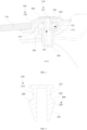
FIG. 1 is a perspective view of an encapsulation structure according to embodiments of the present disclosure; -
FIG. 2 is a partial top view of the encapsulation structure according to embodiments of the present disclosure; -
FIG. 3 is a cross-sectional view taken along A-A inFIG. 2 ; -
FIG. 4 is a cross-sectional view of a buckle according to embodiments of the present disclosure; -
FIG. 5 is a first schematic view showing matching between a main body and an active member according to embodiments of the present disclosure; -
FIG. 6 is a second schematic view showing matching between the main body and the active member according to embodiments of the present disclosure; and -
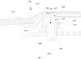
FIG. 7 is a cross-sectional view taken along B-B inFIG. 2 . - 100. main body; 101. engaging cavity; 102. first assembling hole; 110. stop protrusion; 120. encapsulation; 121. avoiding hole; 130. glass plate; 140. reinforcing member; 200. decorative member; 210. buckle; 211. elastic buckling body; 220. limiting protrusion; 221. first contact surface; 222. second contact surface; 300. active member; 301. groove; 310. flange; 311. notch; 400. first sealing member; 500. second sealing member.
- The technical solutions in the embodiments of the present disclosure will be described clearly and completely below with reference to the accompanying drawings in the embodiments of the present disclosure. The described embodiments are merely some of rather than all of the embodiments of the present disclosure. All other embodiments acquired by those skilled in the art without creative efforts based on the embodiments of the present disclosure shall fall within the protection scope of the present disclosure.
- As shown in
FIG. 1 to FIG. 4 , an embodiment discloses an encapsulation structure (not labeled), including amain body 100, adecorative member 200, and anactive member 300. Themain body 100 is provided with anengaging cavity 101 therein. Themain body 100 is provided with afirst assembling hole 102 in communication with the engagingcavity 101. Thedecorative member 200 is provided with abuckle 210. An outer side of thebuckle 210 is provided with a limitingprotrusion 220. Thebuckle 210 has a squeezed state and a recovered state. When thebuckle 210 is squeezed to enable thebuckle 210 to switch from the recovered state to the squeezed state, the limitingprotrusion 220 can pass through thefirst assembling hole 102. When the limitingprotrusion 220 enters theengaging cavity 101 from thefirst assembling hole 102, thebuckle 210 switches from the squeezed state to the recovered state, and the limitingprotrusion 220 abuts against an inner wall of theengaging cavity 101. Theactive member 300 is provided on the side of themain body 100 away from thedecorative member 200. Theactive member 300 is movably matched with themain body 100 and at least partially extends into the engagingcavity 101. Theactive member 300 can move relative to themain body 100 and squeezes thebuckle 210, so that thebuckle 210 switches from the recovered state to the squeezed state. - According to the above encapsulation structure, when it is required to assemble the
decorative member 200 to themain body 100, thebuckle 210 on thedecorative member 200 can be squeezed to enable thebuckle 210 to switch from the recovered state to the squeezed state. At this time, thebuckle 210 may enter theengaging cavity 101 through thefirst assembling hole 102. When thebuckle 210 enters theengaging cavity 101, since thebuckle 210 receives less or no squeezing force, thebuckle 210 can switch from the squeezed state to the recovered state. At this time, the limitingprotrusion 220 on thebuckle 210 can abut against the inner wall of theengaging cavity 101, so as to prevent thebuckle 210 from passing through thefirst assembling hole 102 in a direction away from the engagingcavity 101, thus achieving engaging and assembling of thedecorative member 200 and themain body 100. When it is required to separate thedecorative member 200 from themain body 100, theactive member 300 can be moved to enable theactive member 300 to move in theengaging cavity 101 relative to themain body 100. At this time, theactive member 300 can squeeze thebuckle 210 to enable thebuckle 210 to switch from the recovered state to the squeezed state again. At this time, thebuckle 210 can pass through thefirst assembling hole 102 again and be disengaged from the engagingcavity 101. Therefore, thedecorative member 200 and themain body 100 are detachably matched, and thedecorative member 200 can be replaced. Moreover, disassembly and assembly can be realized by moving theactive member 300, making the disassembly and assembly easier. Thedecorative member 200 is generally arranged outwards, theactive member 300 is located on a side of themain body 100 away from thedecorative member 200, such that thedecorative member 200 cannot be directly disassembled from the side where thedecorative member 200 is located relative to themain body 100, therefore an anti-theft effect is improved in use. - In addition, when the
decorative member 200 is engaged with themain body 100, part of thebuckle 210 is located in theengaging cavity 101. At this time, thebuckle 210 cannot be directly squeezed, and it is required to squeeze thebuckle 210 by moving theactive member 300. That is, after thedecorative member 200 is engaged with themain body 100, the operation of separating thedecorative member 200 from themain body 100 can only be performed through theactive member 300, which can prevent separation of thedecorative member 200 from themain body 100 caused by squeezing of thebuckle 210 in the case of positional interference or the like, so that structural stability is improved after thedecorative member 200 is engaged with themain body 100. - A force may be exerted on the
buckle 210 to squeeze thebuckle 210. At this time, the maximum size of thebuckle 210 is reduced, and thebuckle 210 can enter thefirst assembling hole 102. When thebuckle 210 enters thefirst assembling hole 102 and passes through thefirst assembling hole 102, an outer wall of thebuckle 210 may abut against a hole wall of thefirst assembling hole 102. Specifically, the limitingprotrusion 220 on thebuckle 210 abuts against the hole wall of thefirst assembling hole 102. At this time, thebuckle 210 is still in the squeezed state. As the limitingprotrusion 220 on thebuckle 210 enters theengaging cavity 101 through thefirst assembling hole 102, at least part of the limitingprotrusion 220 no longer abuts against the hole wall of thefirst assembling hole 102. At this time, thebuckle 210 may switch from the squeezed state to the recovered state, the limitingprotrusion 220 is displaced to some extent and can abut against the inner wall of theengaging cavity 101. An overall size of thebuckle 210 is increased, which can prevent thebuckle 210 from separating thefirst assembling hole 102, thus achieving the engagement between thedecorative member 200 and themain body 100. - A size of the
engaging cavity 101 is greater than a diameter of thefirst assembling hole 102, such that during the entry of the limitingprotrusion 220 into the engagingcavity 101 through thefirst assembling hole 102, the limitingprotrusion 220 is displaced by a certain distance along a radial direction of thefirst assembling hole 102, such that thebuckle 210 can switch from the squeezed state to the recovered state. - Optionally, when the limiting
protrusion 220 enters theengaging cavity 101 and thebuckle 210 switches to the recovered state, the limitingprotrusion 220 and thebuckle 210 are still squeezed to some extent. However, thebuckle 210 cannot pass through thefirst assembling hole 102 at this time. - In one of the embodiments, as shown in
FIG. 1 to FIG. 4 , thebuckle 210 includes at least two elastic bucklingbodies 211, and all of the elastic bucklingbodies 211 are provided with the limitingprotrusion 220. Two different elastic bucklingbodies 211 are spaced apart. When thebuckle 210 is in the squeezed state, the elastic bucklingbodies 211 are elastically deformed, and a distance between the limitingprotrusions 220 on the two different elastic bucklingbodies 211 decreases. When the limitingprotrusions 220 enter theengaging cavity 101 through thefirst assembling hole 102, the elastic bucklingbodies 211 are reset, thebuckle 210 switches from the squeezed state to the recovered state, and the distance between the limitingprotrusions 220 on the two different elastic bucklingbodies 211 increases. At this time, after the elastic bucklingbodies 211 enter theengaging cavity 101 from thefirst assembling hole 102, the elastic bucklingbodies 211 may be reset, so that the limitingprotrusion 220 undergoes a certain displacement from the state of abutting against the hole wall of thefirst assembling hole 102, and the distance between the limitingprotrusions 220 on the two different elastic bucklingbodies 211 increases, which can be engaged in theengaging cavity 101, thereby preventing thebuckle 210 from detaching thefirst assembling hole 102, thus making the engagement between thedecorative member 200 and themain body 100 more stable. - Optionally, two elastic buckling
bodies 211 are provided, and the two elastic bucklingbodies 211 are spaced apart. However, in other embodiments, a plurality of elastic bucklingbodies 211 may be provided, all of the elastic bucklingbodies 211 are spaced apart along a circumferential direction. An avoiding space is formed between all of the elastic bucklingbodies 211, and the limitingprotrusion 220 is provided on a side of the elastic bucklingbodies 211 away from the avoiding space. - In other embodiments, the
buckle 210 may include two supports, all of the supports are provided with the above limitingprotrusion 220. At least one of the supports is movably matched with thedecorative member 200, so that a distance between two supports is adjustable. The two supports are provided with a spring. When thebuckle 210 is squeezed, the supports are squeezed, the distance between the two supports may be shortened, and the spring is squeezed. At this time, thebuckle 210 is in the squeezed state and can pass through thefirst assembling hole 102. After the limitingprotrusion 220 enters theengaging cavity 101, the limitingprotrusion 220 no longer abuts against the hole wall of thefirst assembling hole 102. At this time, a resetting effect of the spring may increase the distance between the limitingprotrusions 220 on the two supports, so that thebuckle 210 switches to the recovered state and cannot pass through thefirst assembling hole 102. - Alternatively, the
buckle 210 is an elastic member. When thebuckle 210 is squeezed and elastically deformed, thebuckle 210 switches to the squeezed state. At this time, the limitingprotrusion 220 on thebuckle 210 may be displaced, the maximum outer diameter of thebuckle 210 is reduced, and the buckle can pass through thefirst assembling hole 102. When thebuckle 210 enters theengaging cavity 101, thebuckle 210 is recovered. At this time, the limitingprotrusion 220 may be engaged in theengaging cavity 101, causing the maximum outer diameter of thebuckle 210 to increase. As a result, thebuckle 210 cannot pass through thefirst assembling hole 102 to realize the engagement between thedecorative member 200 and themain body 100. - In an embodiment, as shown in
FIG. 3 and FIG. 4 , an end face of an end of theactive member 300 configured to extend into the engagingcavity 101 is provided with agroove 301. Theactive member 300 moves in a direction close to or away from thebuckle 210. A side of the limitingprotrusion 220 close to theactive member 300 is afirst contact surface 221, and thefirst contact surface 221 is an inclined surface or an arc surface. When theactive member 300 moves in the direction close to thebuckle 210, different limitingprotrusions 220 respectively extend into thegroove 301. A groove wall of thegroove 301 contacts thefirst contact surface 221 and exerts a force on the limitingprotrusions 220, so that the limitingprotrusions 220 are squeezed, thebuckle 210 switches from the recovered state to the squeezed state, and the distance between the limitingprotrusions 220 on the two different elastic bucklingbodies 211 decreases. At this time, by pushing theactive member 300, theactive member 300 is close to thebuckle 210 in theengaging cavity 101, and thebuckle 210 may extend into thegroove 301 of theactive member 300. As a distance of thebuckle 210 extending into thegroove 301 increases, the groove wall of thegroove 301 may exert a force on thefirst contact surface 221, causing the limitingprotrusion 220 to be stressed and causing thebuckle 210 to be squeezed. At this time, thebuckle 210 switches from the recovered state to the squeezed state, a distance between the limitingprotrusions 220 on two different elastic bucklingbodies 211 decreases, and thebuckle 210 may pass through thefirst assembling hole 102 again, which may realize separation of thedecorative member 200 from themain body 100 and is easy to operate. - Optionally, an end of the groove wall of the
groove 301 close to thebuckle 210 is a tapered surface, and an inner diameter of the tapered surface gradually increases in a direction close to thebuckle 210, which can better match the shape of thefirst contact surface 221, increase a contact area, and reduce damage to thefirst contact surface 221. - In other embodiments, the number of the
active member 300 corresponds to the number of the elastic bucklingbody 211. For example, when the number of the elastic bucklingbody 211 is two, the number of theactive member 300 is also two. Oneactive member 300 moves relative to themain body 100 and can abut against one elastic bucklingbody 211, so as to squeeze the elastic bucklingbody 211 and move the elastic bucklingbody 211 close to another elastic bucklingbody 211. At this time, twoactive members 300 may be moved simultaneously, so that the twoactive members 300 squeeze two elastic bucklingbodies 211 respectively to cause the two elastic bucklingbodies 211 to be close to each other, thereby reducing a distance between the limitingprotrusions 220 on the two elastic bucklingbodies 211. At this time, thebuckle 210 switches from the recovered state to the squeezed state and can pass through thefirst assembling hole 102 again. - In an embodiment, as shown in
FIG. 3 and FIG. 4 , a side of the limitingprotrusion 220 away from theactive member 300 is asecond contact surface 222, thesecond contact surface 222 is an inclined surface or an arc surface, and a distance between thesecond contact surface 222 and the elastic bucklingbodies 211 gradually decreases in a direction away from theactive member 300. Thesecond contact surface 222 can facilitate thebuckle 210 to smoothly enter thefirst assembling hole 102 when theactive member 300 squeezes the elastic bucklingbody 211. At the same time, when the limitingprotrusion 220 partially enters theengaging cavity 101 from thefirst assembling hole 102, the contact between the limitingprotrusion 220 and themain body 100 may cause the limitingprotrusion 220 to be subjected to a force in a direction from thefirst assembling hole 102 to theengaging cavity 101, so that thedecorative member 200 and themain body 100 are engaged. - Specifically, when the
decorative member 200 is engaged with themain body 100, the limitingprotrusion 220 is partially located in theengaging cavity 101, so that thesecond contact surface 222 is in contact with a junction between the hole wall of thefirst assembling hole 102 and the inner wall of theengaging cavity 101. At this time, thebuckle 210 is subjected to a force in the direction from thefirst assembling hole 102 to theengaging cavity 101, so that thedecorative member 200 and themain body 100 are engaged. - In an embodiment, as shown in
FIG. 3 andFIG. 5 toFIG. 7 , the side of themain body 100 away from thefirst assembling hole 102 is provided with a second assembling hole (not labeled) in communication with the engagingcavity 101, and theactive member 300 is rotatably provided in the second assembling hole. The end of theactive member 300 configured to extend into the engagingcavity 101 is a push end (not labeled), the push end is externally provided with aflange 310 surrounding the position of the push end. The inner wall of theengaging cavity 101 includes a first wall (not labeled) and a second wall (not labeled) arranged oppositely. A communication point between thefirst assembling hole 102 and theengaging cavity 101 is located on the first wall, a communication point between the second assembling hole and the engaging wall is located on the second wall. The inner wall of theengaging cavity 101 is provided with astop protrusion 110, a distance between thestop protrusion 110 and the second wall is greater than a thickness of theflange 310, and theflange 310 is provided with anotch 311 allowing thestop protrusion 110 to pass through. Referring toFIG. 5 , when it is required to squeeze thebuckle 210 using theactive member 300, theactive member 300 may be rotated, so that thenotch 311 on theflange 310 of theactive member 300 rotates to a position corresponding to thestop protrusion 110. At this time, theactive member 300 may move towards thebuckle 210 through thestop protrusion 110 to squeeze thebuckle 210. Referring toFIG. 6 , when it is not required to use theactive member 300, theactive member 300 may be moved, so that theflange 310 of theactive member 300 is located between thestop protrusion 110 and the second wall, and theactive member 300 is rotated to stagger thestop protrusion 110 from thenotch 311. At this time, theactive member 300 is limited between the limitingprotrusion 220 and the second wall and may not move freely. Therefore, separation of thedecorative member 200 from themain body 100 due to squeezing of thebuckle 210 caused by an accidental touch on theactive member 300 can be prevented, ensuring stability of the engagement between thedecorative member 200 and themain body 100. - In an embodiment, as shown in
FIG. 3 , when the limitingprotrusion 220 is located in theengaging cavity 101, thefirst contact surface 221 abuts against the groove wall of thegroove 301. When the limitingprotrusion 220 extends into the engagingcavity 101, thefirst contact surface 221 abuts against the groove wall of thegroove 301 of theactive member 300, thus enabling theactive member 300 and thebuckle 210 to exert forces on each other. Theactive member 300 and thebuckle 210 are fixed in theengaging cavity 101. In the above encapsulation structure, theactive member 300 and thebuckle 210 are not prone to displace relative to each other in a vibrating environment, which can reduce noise or abnormal noise. - In an embodiment, an inner diameter of the
groove 301 is less than or equal to a diameter of thefirst assembling hole 102. At this time, when thegroove 301 squeezes thebuckle 210, thebuckle 210 in the squeezed state can be ensured to pass through thefirst assembling hole 102 from the engagingcavity 101, thereby facilitating the separation of thedecorative member 200 from themain body 100. - Specifically, the inner diameter of the
groove 301 is less than the diameter of thefirst assembling hole 102. - In an embodiment, as shown in
FIG. 3 , the encapsulation structure further includes afirst sealing member 400 and asecond sealing member 500. Thefirst sealing member 400 is arranged between thedecorative member 200 and themain body 100, and thefirst sealing member 400 is arranged around thebuckle 210. Thesecond sealing member 500 is arranged on the side of themain body 100 away from thedecorative member 200, and thesecond sealing member 500 is arranged around theactive member 300. Through thefirst sealing member 400 and thesecond sealing member 500, sealing performance of the above encapsulation structure can be improved, water seepage can be prevented, and noise can be reduced. - Optionally, the
first sealing member 400 and thesecond sealing member 500 are foam gaskets, which have good sealing effects and have certain buffering and shock-absorbing effects. - In an embodiment, as shown in
FIG. 3 andFIG. 7 , themain body 100 includes anencapsulation 120, aglass plate 130, and a reinforcingmember 140. Theencapsulation 120 is connected to an edge of theglass plate 130 and the reinforcingmember 140, respectively. The reinforcingmember 140 and thedecorative member 200 are located on two sides of theencapsulation 120 respectively. The engagingcavity 101 and thefirst assembling hole 102 are both arranged on the reinforcingmember 140. Theencapsulation 120 is provided with an avoiding hole 121 arranged corresponding to thefirst assembling hole 102, and thebuckle 210 passes through the avoiding hole 121 and thefirst assembling hole 102 sequentially and extends into the engagingcavity 101. Theencapsulation 120 is located at the edge of theglass plate 130 and is connected to theglass plate 130. The reinforcingmember 140 can provide structural support for theencapsulation 120. Thedecorative member 200 is located on the side of theencapsulation 120 away from the reinforcingmember 140 and plays a decorative role. - Optionally, the
decorative member 200 is in the shape of a strip, and theencapsulation 120 is provided with placement grooves that match edges on two sides of thedecorative member 200 to limit thedecorative member 200 and guide an installation position. - Optionally, the
glass plate 130 may be made of tempered glass, laminated glass, semi-tempered laminated glass, or other glass materials. - Optionally, the
encapsulation 120 may be made of polyvinyl chloride (PVC), thermoplastic elastomer (TPE), or other materials. Material hardness of theencapsulation 120 may be Shore A60 to A90. - Optionally, the
decorative member 200 may be stainless steel, aluminum alloy, polymethyl methacrylate (PMMA), polycarbonate and acrylonitrile butadiene styrene (PC+ABS, engineering plastic alloy), or other materials. A side of thedecorative member 200 away from theencapsulation 120 may be a high-gloss surface or a matte surface. - Optionally, the
buckle 210 may be made of a plastic material, such as polyoxymethylene (POM), polypropylene with glass fiber (PP+GF), polyamide 66 with glass fiber (PA66+GF), polyamide 6 with glass fiber (PA6+GF), PC+ABS, or styrene acrylonitrile resin (SAN). - Alternatively, the
buckle 210 may be made of an elastic metal material, such as spring steel. - Optionally, the reinforcing
member 140 may be made of hard plastic such as PA66+GF, PA6+GF, or PP+GF, or metal such as carbon steel or stainless steel. - Optionally, the
glass plate 130, theencapsulation 120, and the reinforcingmember 140 may be integrally injection molded. - Optionally, the
buckle 210 may be fixed to thedecorative member 200 by tape bonding, PU glue bonding, hot melting, welding, or other manners. - An embodiment discloses a vehicle, including the encapsulation structure as described in any one of the above embodiments.
- According to the above vehicle, when it is required to assemble the
decorative member 200 with themain body 100, thebuckle 210 on thedecorative member 200 can be squeezed to enable thebuckle 210 to switch from the recovered state to the squeezed state. At this time, thebuckle 210 may enter theengaging cavity 101 through thefirst assembling hole 102. When thebuckle 210 enters theengaging cavity 101, since thebuckle 210 receives less or no squeezing force, thebuckle 210 can switch from the squeezed state to the recovered state. At this time, the limitingprotrusion 220 on thebuckle 210 can abut against the inner wall of theengaging cavity 101 to prevent thebuckle 210 from passing through thefirst assembling hole 102 in a direction away from the engagingcavity 101 , thus achieving engaging and assembling of thedecorative member 200 and themain body 100. When it is required to separate thedecorative member 200 from themain body 100, theactive member 300 can be moved to enable theactive member 300 to move in theengaging cavity 101 relative to themain body 100. At this time, theactive member 300 can squeeze thebuckle 210 to enable thebuckle 210 to switch from the recovered state to the squeezed state again. At this time, thebuckle 210 can pass through thefirst assembling hole 102 again and be disengaged from the engagingcavity 101. Therefore, thedecorative member 200 and themain body 100 are detachably matched, and thedecorative member 200 can be replaced. Moreover, disassembly and assembly can be realized by moving theactive member 300, making the disassembly and assembly easier. Thedecorative member 200 is generally arranged outwards, theactive member 300 is located on the side of themain body 100 away from thedecorative member 200, such that thedecorative member 200 cannot be directly disassembled from the side where thedecorative member 200 is located relative to themain body 100, therefore an anti-theft effect is improved in use. - Specifically, the side of the reinforcing
member 140 away from theencapsulation 120 is used to be connected to a vehicle body, and thesecond sealing member 500 is arranged between the reinforcingmember 140 and the vehicle body. - The technical features in the above embodiments may be randomly combined. For concise description, not all possible combinations of the technical features in the above embodiments are described. However, all the combinations of the technical features are to be considered as falling within the scope described in this specification provided that they do not conflict with each other.
- The above embodiments only describe several implementations of the present disclosure, and their description is specific and detailed, but cannot therefore be understood as a limitation on the patent scope of the present disclosure. It should be noted that those of ordinary skill in the art may further make variations and improvements without departing from the concept of the present disclosure, and these all fall within the protection scope of the present disclosure. Therefore, the patent protection scope of the present disclosure should be subject to the appended claims.
- In the description of the present disclosure, the orientation or position relationships indicated by the terms "central", "longitudinal", "transverse", "length", "width", "thickness", "upper", "lower", "front", "back", "left", "right", "vertical", "horizontal", "top", "bottom", "inner", "outer", "clockwise", "counterclockwise", "axial", "radial", "circumferential", and the like are based on the orientation or position relationships shown in the accompanying drawings and are intended to facilitate the description of the present disclosure and simplify the description only, rather than indicating or implying that the apparatus or element referred to must have a particular orientation or be constructed and operated in a particular orientation, and therefore are not to be interpreted as limiting the present disclosure.
- In the description of the present disclosure, the terms "first" and "second" are used for descriptive purposes only, which cannot be construed as indicating or implying a relative importance, or implicitly specifying the number of the indicated technical features. Thus, the features defined with "first" and "second" may explicitly or implicitly include one or more features. In the description of the present disclosure, "a plurality of" means two or more, such as two or three, unless otherwise defined explicitly and specifically.
- In the present disclosure, unless otherwise specified and defined explicitly, the terms "install", "connect", "join", and "fix" should be understood in a broad sense. For example, they may refer to a fixed connection, a detachable connection, or an integral connection; may refer to a mechanical connection or electrical connection; and may refer to a direct connection, an indirect connection via an intermediate medium, an internal connection between two elements, or interaction between two elements. Those of ordinary skill in the art can understand specific meanings of these terms in the present disclosure according to specific situations.
- In the present disclosure, unless otherwise specified and defined explicitly, the expression a first feature being "on" or "under" a second feature may be the case that the first feature is in direct contact with the second feature, or the first feature is in indirect contact with the second feature via an intermediate medium. Furthermore, the expression the first feature being "over", "above" and "on top of" the second feature may be the case that the first feature is directly above or obliquely above the second feature, or only means that the level of the first feature is higher than that of the second feature. The expression the first feature being "below", "underneath" or "under" the second feature may be the case that the first feature is directly underneath or obliquely underneath the second feature, or only means that the level of the first feature is lower than that of the second feature.
- It should be noted that when one element is referred to as "fixed to" or "arranged on" another element, it may be directly disposed on the other element or an intermediate element may exist. When one element is considered to be "connected to" another element, it may be directly connected to the other element or an intermediate element may co-exist. The terms "vertical", "horizontal", "upper", "lower", "left", "right" and similar expressions used herein are for illustrative purposes only and do not represent the only implementation.
- The technical features in the above embodiments may be randomly combined. For concise description, not all possible combinations of the technical features in the above embodiments are described. However, all the combinations of the technical features are to be considered as falling within the scope described in this specification provided that they do not conflict with each other.
- The above embodiments only describe several implementations of the present disclosure, and their description is specific and detailed, but cannot therefore be understood as a limitation on the patent scope of the present disclosure. It should be noted that those of ordinary skill in the art may further make variations and improvements without departing from the concept of the present disclosure, and these all fall within the protection scope of the present disclosure. Therefore, the patent protection scope of the present disclosure should be subject to the appended claims.
Claims (10)
- An encapsulation structure, comprising:a main body provided with an engaging cavity therein, and the main body being provided with a first assembling hole in communication with the engaging cavity;a decorative member provided with a buckle, wherein an outer side of the buckle is provided with a limiting protrusion, the buckle has a squeezed state and a recovered state, when the buckle is squeezed to enable the buckle to switch from the recovered state to the squeezed state, the limiting protrusion is capable of passing through the first assembling hole, when the limiting protrusion enters the engaging cavity from the first assembling hole, the buckle switches from the squeezed state to the recovered state, and the limiting protrusion abuts against an inner wall of the engaging cavity; andan active member provided on a side of the main body away from the decorative member, wherein the active member is movably matched with the main body and at least partially extends into the engaging cavity, and the active member is capable of moving relative to the main body and squeezing the buckle, so that the buckle switches from the recovered state to the squeezed state.
- The encapsulation structure according to claim 1, wherein the buckle comprises at least two elastic buckling bodies, all of the elastic buckling bodies are provided with the limiting protrusion, two different elastic buckling bodies are spaced apart, when the buckle is in the squeezed state, the elastic buckling bodies are elastically deformed, and a distance between the limiting protrusions on the two different elastic buckling bodies decreases, when the limiting protrusions enter the engaging cavity from the first assembling hole, the elastic buckling bodies are reset, the buckle switches from the squeezed state to the recovered state, and the distance between the limiting protrusions on the two different elastic buckling bodies increases.
- The encapsulation structure according to claim 2, wherein an end face of an end of the active member configured to extend into the engaging cavity is provided with a groove, the active member moves in a direction close to or away from the buckle, a side of the limiting protrusion close to the active member is a first contact surface, the first contact surface is an inclined surface or an arc surface, when the active member moves in the direction close to the buckle, different limiting protrusions extend into the groove, respectively, a groove wall of the groove contacts the first contact surface and exerts a force on the limiting protrusions, so that the limiting protrusions are squeezed, the buckle switches from the recovered state to the squeezed state, and the distance between the limiting protrusions on the two different elastic buckling bodies decreases.
- The encapsulation structure according to claim 3, wherein a side of the limiting protrusion away from the active member is a second contact surface, the second contact surface is an inclined surface or an arc surface, and a distance between the second contact surface and the elastic buckling bodies gradually decreases in a direction away from the active member.
- The encapsulation structure according to claim 3, wherein a side of the main body away from the first assembling hole is provided with a second assembling hole in communication with the engaging cavity, the active member is rotatably provided in the second assembling hole, the end of the active member configured to extend into the engaging cavity is a push end, the push end is externally provided with a flange surrounding a position of the push end, the inner wall of the engaging cavity comprises a first wall and a second wall arranged oppositely, a communication point between the first assembling hole and the engaging cavity is located on the first wall, a communication point between the second assembling hole and the engaging cavity is located on the second wall, the inner wall of the engaging cavity is provided with a stop protrusion, a distance between the stop protrusion and the second wall is greater than a thickness of the flange, and the flange is provided with a notch allowing the stop protrusion to pass through.
- The encapsulation structure according to claim 3, wherein when the limiting protrusion is located in the engaging cavity, the first contact surface abuts against the groove wall of the groove.
- The encapsulation structure according to claim 3, wherein an inner diameter of the groove is less than or equal to a diameter of the first assembling hole.
- The encapsulation structure according to any one of claims 1 to 7, further comprising a first sealing member and a second sealing member, the first sealing member being arranged between the decorative member and the main body, the first sealing member being arranged around the buckle, the second sealing member being arranged on the side of the main body away from the decorative member, and the second sealing member being arranged around the active member.
- The encapsulation structure according to any one of claims 1 to 7, wherein the main body comprises an encapsulation, a glass plate, and a reinforcing member, the encapsulation is connected to an edge of the glass plate and the reinforcing member, respectively, the reinforcing member and the decorative member are located on two sides of the encapsulation, respectively, the engaging cavity and the first assembling hole are both arranged on the reinforcing member, the encapsulation is provided with an avoiding hole corresponding to the first assembling hole, and the buckle passes through the avoiding hole and the first assembling hole sequentially and extends into the engaging cavity.
- A vehicle, comprising the encapsulation structure according to any one of claims 1 to 9.
Applications Claiming Priority (2)
| Application Number | Priority Date | Filing Date | Title |
|---|---|---|---|
| CN202210231939.3A CN114701337A (en) | 2022-03-09 | 2022-03-09 | Edge covering structure and vehicle |
| PCT/CN2023/080188 WO2023169446A1 (en) | 2022-03-09 | 2023-03-08 | Hemming structure and vehicle |
Publications (2)
| Publication Number | Publication Date |
|---|---|
| EP4454911A1 true EP4454911A1 (en) | 2024-10-30 |
| EP4454911A4 EP4454911A4 (en) | 2025-03-26 |
Family
ID=82168989
Family Applications (1)
| Application Number | Title | Priority Date | Filing Date |
|---|---|---|---|
| EP23766024.6A Pending EP4454911A4 (en) | 2022-03-09 | 2023-03-08 | HEMMING STRUCTURE AND VEHICLE |
Country Status (5)
| Country | Link |
|---|---|
| US (1) | US20250162391A1 (en) |
| EP (1) | EP4454911A4 (en) |
| JP (1) | JP7805090B2 (en) |
| CN (1) | CN114701337A (en) |
| WO (1) | WO2023169446A1 (en) |
Families Citing this family (2)
| Publication number | Priority date | Publication date | Assignee | Title |
|---|---|---|---|---|
| CN114701337A (en) * | 2022-03-09 | 2022-07-05 | 福耀玻璃工业集团股份有限公司 | Edge covering structure and vehicle |
| CN219937522U (en) * | 2023-06-25 | 2023-10-31 | 泰科电子(苏州)有限公司 | Connector parts and connectors |
Family Cites Families (22)
| Publication number | Priority date | Publication date | Assignee | Title |
|---|---|---|---|---|
| JPS57415U (en) * | 1980-05-31 | 1982-01-05 | ||
| JP2527347Y2 (en) * | 1990-09-17 | 1997-02-26 | 株式会社ニフコ | Mounting structure for metal malls for automobile windows |
| JPH0459542U (en) * | 1990-09-29 | 1992-05-21 | ||
| DE10252597B4 (en) * | 2002-11-12 | 2005-01-27 | Metzeler Automotive Profile Systems Gmbh | Fixing clip, in particular for attaching a sealing and / or guide frame enclosing a window pane to the bodywork of a motor vehicle |
| DE10350802B4 (en) * | 2003-10-29 | 2016-07-21 | Henniges Automotive Gmbh & Co. Kg | Plate-like element, in particular glass pane of a vehicle glazing, and method for its production |
| CN101688549B (en) * | 2007-07-12 | 2011-11-30 | 百乐仕株式会社 | Latching device |
| DE202010001223U1 (en) * | 2010-01-20 | 2010-04-01 | Richard Fritz Gmbh + Co. Kg | disc unit |
| WO2011089650A1 (en) * | 2010-01-22 | 2011-07-28 | 三菱電機株式会社 | Fastener member and fastening structure |
| CN103153760B (en) * | 2010-09-28 | 2015-09-09 | 本田技研工业株式会社 | Vehicle cowl upper locating structure |
| JP5847021B2 (en) * | 2012-06-04 | 2016-01-20 | 三菱電機ビルテクノサービス株式会社 | Substrate removal jig |
| BR112016028669A2 (en) * | 2014-06-12 | 2017-08-22 | Illinois Tool Works | clip mount |
| CN207657579U (en) * | 2018-01-03 | 2018-07-27 | 临朐瑞星塑胶制品有限公司 | A kind of sealing strip fixed structure |
| CN108407584A (en) * | 2018-02-26 | 2018-08-17 | 福耀玻璃工业集团股份有限公司 | A kind of vehicle glass assembly product |
| CN108437910B (en) * | 2018-05-02 | 2019-11-08 | 福耀玻璃工业集团股份有限公司 | An edge-wrapped glass assembly with decorative strips |
| CN208439190U (en) * | 2018-06-13 | 2019-01-29 | 广州尚牛设计有限公司 | A silent structure for car window trim strip |
| CN209795373U (en) * | 2019-04-02 | 2019-12-17 | 福耀玻璃工业集团股份有限公司 | A glass edging assembly with decorative panels |
| CN211222995U (en) * | 2019-11-08 | 2020-08-11 | 观致汽车有限公司 | Plug-in window frame decorative plate sealing assembly |
| CN111746426A (en) * | 2020-06-18 | 2020-10-09 | 福耀玻璃工业集团股份有限公司 | An edge-covered glass assembly with a trim panel |
| CN112109532A (en) * | 2020-07-01 | 2020-12-22 | 汉腾汽车有限公司 | Card inserting device for front windshield glass decoration strip |
| WO2022029000A1 (en) * | 2020-08-06 | 2022-02-10 | Agc Glass Europe | Window unit comprising a glazing panel and a frame |
| CN214450178U (en) * | 2021-03-30 | 2021-10-22 | 长城汽车股份有限公司 | Door window structure assembly and vehicle |
| CN114701337A (en) * | 2022-03-09 | 2022-07-05 | 福耀玻璃工业集团股份有限公司 | Edge covering structure and vehicle |
-
2022
- 2022-03-09 CN CN202210231939.3A patent/CN114701337A/en active Pending
-
2023
- 2023-03-08 WO PCT/CN2023/080188 patent/WO2023169446A1/en not_active Ceased
- 2023-03-08 US US18/730,327 patent/US20250162391A1/en active Pending
- 2023-03-08 JP JP2024543964A patent/JP7805090B2/en active Active
- 2023-03-08 EP EP23766024.6A patent/EP4454911A4/en active Pending
Also Published As
| Publication number | Publication date |
|---|---|
| WO2023169446A1 (en) | 2023-09-14 |
| EP4454911A4 (en) | 2025-03-26 |
| US20250162391A1 (en) | 2025-05-22 |
| CN114701337A (en) | 2022-07-05 |
| JP2025503946A (en) | 2025-02-06 |
| JP7805090B2 (en) | 2026-01-23 |
Similar Documents
| Publication | Publication Date | Title |
|---|---|---|
| US20250162391A1 (en) | Hemming structure and vehicle | |
| US7735538B2 (en) | Door shutter | |
| US20090007498A1 (en) | Weather strip | |
| JP2007244037A (en) | Fitting | |
| CN110417089A (en) | A kind of wireless headset charging box | |
| CN208544208U (en) | touch sensor unit | |
| US20030209959A1 (en) | Runner for a drawer | |
| CN111053335A (en) | Connection mechanism of wrist-worn device and wrist-worn device | |
| CN210807848U (en) | Housing assembly for electronic equipment and electronic equipment | |
| EP3550809B1 (en) | Sliding mechanism and terminal device provided with same | |
| JP2009273250A (en) | Cable guide | |
| CN106766597B (en) | Assembly structure of refrigerator door frame ornamental strip and handle | |
| CN102232675B (en) | Zipper head | |
| US20250162534A1 (en) | Safety belt sliding assembly and vehicle | |
| CN114530723B (en) | Charging gun sealed housing and integrated charging gun | |
| CN216554839U (en) | Long-life canned type buckle | |
| JP4825068B2 (en) | the mall | |
| CN222863825U (en) | Pin, skylight assembly and vehicle | |
| EP4727273A1 (en) | Mounting assembly for middle bezel, and electronic device | |
| CN220053962U (en) | Buckle assembly for vehicle wheel trim panel and vehicle | |
| CN215058726U (en) | Low insertion force buckle | |
| JP2006051906A (en) | Ornamental flame member for vehicle | |
| CN105450817B (en) | Button and its mounting structure | |
| CN114442743B (en) | Interface protection structure and mobile terminal | |
| CN209838852U (en) | Housing with snap connection |
Legal Events
| Date | Code | Title | Description |
|---|---|---|---|
| STAA | Information on the status of an ep patent application or granted ep patent |
Free format text: STATUS: THE INTERNATIONAL PUBLICATION HAS BEEN MADE |
|
| PUAI | Public reference made under article 153(3) epc to a published international application that has entered the european phase |
Free format text: ORIGINAL CODE: 0009012 |
|
| STAA | Information on the status of an ep patent application or granted ep patent |
Free format text: STATUS: REQUEST FOR EXAMINATION WAS MADE |
|
| 17P | Request for examination filed |
Effective date: 20240722 |
|
| AK | Designated contracting states |
Kind code of ref document: A1 Designated state(s): AL AT BE BG CH CY CZ DE DK EE ES FI FR GB GR HR HU IE IS IT LI LT LU LV MC ME MK MT NL NO PL PT RO RS SE SI SK SM TR |
|
| A4 | Supplementary search report drawn up and despatched |
Effective date: 20250220 |
|
| RIC1 | Information provided on ipc code assigned before grant |
Ipc: B60R 13/06 20060101ALI20250214BHEP Ipc: F16B 21/08 20060101ALI20250214BHEP Ipc: F16B 5/12 20060101ALI20250214BHEP Ipc: B60R 13/04 20060101ALI20250214BHEP Ipc: B60J 10/70 20160101ALI20250214BHEP Ipc: B60J 10/30 20160101ALI20250214BHEP Ipc: B60J 10/265 20160101AFI20250214BHEP |
|
| DAV | Request for validation of the european patent (deleted) | ||
| DAX | Request for extension of the european patent (deleted) | ||
| STAA | Information on the status of an ep patent application or granted ep patent |
Free format text: STATUS: EXAMINATION IS IN PROGRESS |
|
| 17Q | First examination report despatched |
Effective date: 20250908 |