EP4454569A1 - Ultraschallscanner und ultraschallsignalkorrekturverfahren für ultraschallscanner - Google Patents
Ultraschallscanner und ultraschallsignalkorrekturverfahren für ultraschallscanner Download PDFInfo
- Publication number
- EP4454569A1 EP4454569A1 EP21969149.0A EP21969149A EP4454569A1 EP 4454569 A1 EP4454569 A1 EP 4454569A1 EP 21969149 A EP21969149 A EP 21969149A EP 4454569 A1 EP4454569 A1 EP 4454569A1
- Authority
- EP
- European Patent Office
- Prior art keywords
- ultrasound
- scanner
- echo signals
- bladder
- transducer
- Prior art date
- Legal status (The legal status is an assumption and is not a legal conclusion. Google has not performed a legal analysis and makes no representation as to the accuracy of the status listed.)
- Pending
Links
Images


Classifications
-
- A—HUMAN NECESSITIES
- A61—MEDICAL OR VETERINARY SCIENCE; HYGIENE
- A61B—DIAGNOSIS; SURGERY; IDENTIFICATION
- A61B8/00—Diagnosis using ultrasonic, sonic or infrasonic waves
- A61B8/08—Clinical applications
-
- A—HUMAN NECESSITIES
- A61—MEDICAL OR VETERINARY SCIENCE; HYGIENE
- A61B—DIAGNOSIS; SURGERY; IDENTIFICATION
- A61B8/00—Diagnosis using ultrasonic, sonic or infrasonic waves
- A61B8/44—Constructional features of the ultrasonic, sonic or infrasonic diagnostic device
- A61B8/4444—Constructional features of the ultrasonic, sonic or infrasonic diagnostic device related to the probe
- A61B8/4461—Features of the scanning mechanism, e.g. for moving the transducer within the housing of the probe
- A61B8/4466—Features of the scanning mechanism, e.g. for moving the transducer within the housing of the probe involving deflection of the probe
-
- A—HUMAN NECESSITIES
- A61—MEDICAL OR VETERINARY SCIENCE; HYGIENE
- A61B—DIAGNOSIS; SURGERY; IDENTIFICATION
- A61B8/00—Diagnosis using ultrasonic, sonic or infrasonic waves
- A61B8/08—Clinical applications
- A61B8/0858—Clinical applications involving measuring tissue layers, e.g. skin, interfaces
-
- A—HUMAN NECESSITIES
- A61—MEDICAL OR VETERINARY SCIENCE; HYGIENE
- A61B—DIAGNOSIS; SURGERY; IDENTIFICATION
- A61B8/00—Diagnosis using ultrasonic, sonic or infrasonic waves
- A61B8/13—Tomography
- A61B8/14—Echo-tomography
- A61B8/145—Echo-tomography characterised by scanning multiple planes
-
- A—HUMAN NECESSITIES
- A61—MEDICAL OR VETERINARY SCIENCE; HYGIENE
- A61B—DIAGNOSIS; SURGERY; IDENTIFICATION
- A61B8/00—Diagnosis using ultrasonic, sonic or infrasonic waves
- A61B8/42—Details of probe positioning or probe attachment to the patient
- A61B8/4245—Details of probe positioning or probe attachment to the patient involving determining the position of the probe, e.g. with respect to an external reference frame or to the patient
- A61B8/4254—Details of probe positioning or probe attachment to the patient involving determining the position of the probe, e.g. with respect to an external reference frame or to the patient using sensors mounted on the probe
-
- A—HUMAN NECESSITIES
- A61—MEDICAL OR VETERINARY SCIENCE; HYGIENE
- A61B—DIAGNOSIS; SURGERY; IDENTIFICATION
- A61B8/00—Diagnosis using ultrasonic, sonic or infrasonic waves
- A61B8/44—Constructional features of the ultrasonic, sonic or infrasonic diagnostic device
- A61B8/4427—Device being portable or laptop-like
-
- A—HUMAN NECESSITIES
- A61—MEDICAL OR VETERINARY SCIENCE; HYGIENE
- A61B—DIAGNOSIS; SURGERY; IDENTIFICATION
- A61B8/00—Diagnosis using ultrasonic, sonic or infrasonic waves
- A61B8/44—Constructional features of the ultrasonic, sonic or infrasonic diagnostic device
- A61B8/4444—Constructional features of the ultrasonic, sonic or infrasonic diagnostic device related to the probe
- A61B8/4461—Features of the scanning mechanism, e.g. for moving the transducer within the housing of the probe
-
- A—HUMAN NECESSITIES
- A61—MEDICAL OR VETERINARY SCIENCE; HYGIENE
- A61B—DIAGNOSIS; SURGERY; IDENTIFICATION
- A61B8/00—Diagnosis using ultrasonic, sonic or infrasonic waves
- A61B8/44—Constructional features of the ultrasonic, sonic or infrasonic diagnostic device
- A61B8/4444—Constructional features of the ultrasonic, sonic or infrasonic diagnostic device related to the probe
- A61B8/4472—Wireless probes
-
- A—HUMAN NECESSITIES
- A61—MEDICAL OR VETERINARY SCIENCE; HYGIENE
- A61B—DIAGNOSIS; SURGERY; IDENTIFICATION
- A61B8/00—Diagnosis using ultrasonic, sonic or infrasonic waves
- A61B8/48—Diagnostic techniques
- A61B8/483—Diagnostic techniques involving the acquisition of a 3D volume of data
-
- A—HUMAN NECESSITIES
- A61—MEDICAL OR VETERINARY SCIENCE; HYGIENE
- A61B—DIAGNOSIS; SURGERY; IDENTIFICATION
- A61B8/00—Diagnosis using ultrasonic, sonic or infrasonic waves
- A61B8/52—Devices using data or image processing specially adapted for diagnosis using ultrasonic, sonic or infrasonic waves
- A61B8/5207—Devices using data or image processing specially adapted for diagnosis using ultrasonic, sonic or infrasonic waves involving processing of raw data to produce diagnostic data, e.g. for generating an image
-
- A—HUMAN NECESSITIES
- A61—MEDICAL OR VETERINARY SCIENCE; HYGIENE
- A61B—DIAGNOSIS; SURGERY; IDENTIFICATION
- A61B8/00—Diagnosis using ultrasonic, sonic or infrasonic waves
- A61B8/52—Devices using data or image processing specially adapted for diagnosis using ultrasonic, sonic or infrasonic waves
- A61B8/5215—Devices using data or image processing specially adapted for diagnosis using ultrasonic, sonic or infrasonic waves involving processing of medical diagnostic data
- A61B8/5223—Devices using data or image processing specially adapted for diagnosis using ultrasonic, sonic or infrasonic waves involving processing of medical diagnostic data for extracting a diagnostic or physiological parameter from medical diagnostic data
-
- A—HUMAN NECESSITIES
- A61—MEDICAL OR VETERINARY SCIENCE; HYGIENE
- A61B—DIAGNOSIS; SURGERY; IDENTIFICATION
- A61B8/00—Diagnosis using ultrasonic, sonic or infrasonic waves
- A61B8/54—Control of the diagnostic device
-
- A—HUMAN NECESSITIES
- A61—MEDICAL OR VETERINARY SCIENCE; HYGIENE
- A61B—DIAGNOSIS; SURGERY; IDENTIFICATION
- A61B8/00—Diagnosis using ultrasonic, sonic or infrasonic waves
- A61B8/44—Constructional features of the ultrasonic, sonic or infrasonic diagnostic device
- A61B8/4483—Constructional features of the ultrasonic, sonic or infrasonic diagnostic device characterised by features of the ultrasound transducer
Definitions
- the present invention relates to a portable bladder scanner that measures the volume of urine filling the bladder using a 3-dimensional scanning ultrasound scanner. More specifically, the present invention relates to an ultrasound scanner that extracts the physical position error of the ultrasound transducer generated during the ultrasound scanning process according to the manual rotation by the operator, corrects the coordinates of the ultrasound echo signal using the extracted physical position error and allows accurate measurement of the volume of urine inside the bladder.
- a special purpose portable 3D ultrasound scanner for measuring the volume of urine filled in the bladder is referred to as a 'bladder scanner'.
- the main purpose of the bladder scanner is to measure the volume of urine inside the bladder. Therefore, the main function of the bladder scanner is to automatically segment the bladder area from a 3D ultrasound image, calculate the volume of the segmented bladder area, and display the calculated volume of the bladder area as a numerical value.
- a secondary function of the bladder scanner is to output the acquired ultrasound image to a display device.
- the bladder scanner described above is characterized by minimizing its size and weight so that it can be carried by medical person. For this reason, the bladder scanner is specialized for measuring the volume of urine, and other secondary functions are generally eliminated.
- the bladder scanner is sometimes manufactured with a structure that includes an ultrasound transducer composed of a single element and motors that drive it.
- the bladder scanner with this structure often uses an operation method of scanning ultrasound beams while rotating the ultrasonic transducer using the motors for sector scans.
- 3D ultrasound scanning of the bladder it is necessary to sequentially perform a sector scan of a single plane in multiple directions to obtain multiple 2D cross-sectional ultrasound images of the bladder. This requires scanning the transducer in two directions. Additionally, for scanning in two directions, two motors driven in different directions can be provided.
- the ultrasound scanner with this structure has a problem in that the size and weight of the motor drive unit increase.
- the portable bladder scanner in order to make the portable bladder scanner as small and light as possible, it can be manufactured with a structure equipped with a single motor.
- the bladder scanner of this structure is configured to automatically rotate in one direction using the single motor and to rotate manually in the other direction using the operator's hand movements.
- the present invention relates to a method of reducing measurement errors in volume of urine that may occur in the bladder scanner of the ultrasound scanning method using manual rotation by an operator.
- Bladder scanners are manufactured to be used solely to measure the volume of the bladder, and therefore have the characteristics of being smaller in size and cheaper than general ultrasound scanners.
- an ultrasound transducer consisting of a single element is generally equipped.
- the general ultrasound scanners are equipped with a phased array transducer in which multiple transducers are arranged in a line or plane shape, so they are expensive and the operation method is complicated. Therefore, the general ultrasound scanners have limitations that make it difficult to use them as portable bladder scanners. Therefore, in the bladder scanner, it is common to use an ultrasound transducer composed of a single element.
- the bladder scanner that uses an ultrasound transducer composed of a single element requires three-dimensional ultrasound scanning to obtain volumetric image of the bladder.
- the bladder scanner generates a 3-dimensional ultrasound image using a plurality of the 2-dimensional cross-section ultrasound images which are obtained by performing a plurality of the sector scans at various angles.
- FIG. 1 is a structural diagram showing a general bladder scanner.
- the general bladder scanner 10 includes a control unit that controls overall operation, an ultrasound transducer 110, a first motor 120, a second motor 130 and a motor drive unit.
- the bladder scanner described above has an ultrasound transducer 110 at the bottom.
- the thickness of the transducer is determined by the frequency of ultrasound, and the frequency used for bladder scanning is generally about 2-3 MHz.
- the Transducer is generally circular.
- the diameter of the transducer is determined by considering the maximum depth of the bladder to be measured by the ultrasound signal, and is generally about 10-15 mm.
- the ultrasound transducer 110 is mechanically connected to the motor drive unit.
- the motor drive unit performs ultrasound scanning by driving the first motor and the second motor to rotate the ultrasound transducer in two different directions.
- the motor drive unit generally uses a sector scan method to obtain a two-dimensional cross-sectional ultrasound image.
- the ultrasound transducer 110, the motor drive unit, and the ultrasound driving circuit unit are placed and fixed within the covering 140 of the bladder scanner.
- FIG. 2 is a schematic diagram illustrating a sector scan for obtaining two-dimensional ultrasound signals by rotating an ultrasound transducer using a motor in a general bladder scanner.
- the ultrasound transducer is rotated by an angle ⁇
- the ultrasound beam coming from the transducer rotates by an angle ⁇ about the central axis y.
- the rotation axis of the ultrasound transducer places the center point 0 on the bottom surface of the ultrasound transducer.
- FIGS. 3A and 3B are diagrams showing the direction in which the rotation axis of the ultrasound transducer is rotated according to a conventional method in a general bladder scanner.
- a sector scan as shown in FIG. 3A can be performed.
- the number of scanning lines is M+1, and the separation angle ⁇ of adjacent scanning lines is preferably set to a constant value.
- the angle of the sector scan should be set to scan the entire bladder, and is usually around 120°.
- a sector scan generates one two-dimensional cross-sectional image. Therefore, in order to obtain a 3D image, the sector scans must be performed repeatedly while changing the scanning angle.
- a commonly used method is to perform the sector scans as shown in FIG. 3A while the transducer is rotated at a constant angular velocity about the central y-axis as shown in FIG. 3B .
- this rotation angle is indicated as ⁇ .
- a three-dimensional scanning trajectory can be generated by performing one sector scan, rotating by ⁇ , and then repeating the sector scan. By sequentially rotating 180° along the ⁇ direction, a 3D volume image can be obtained.
- FIG. 4 is a schematic diagram showing the direction in which the bladder scanner is rotated by driving the motor to obtain a 3D image in a bladder scanner equipped with two motors driven in different directions.
- a three-dimensional image of the area including the bladder can be obtained.
- the 3D scanning of a bladder scanner is very slow compared to a general ultrasound scanner, and the scanning speed is usually several seconds.
- the sector scans are performed in a plurality of different directions including the bladder to obtain a plurality of two-dimensional ultrasound images for different positions, and the volume of urine can be measured by using the obtained plurality of two-dimensional ultrasound images.
- the algorithm for measuring the volume of urine from a plurality of two-dimensional ultrasound images is a known technology, and various methods are used.
- the urine volume measurement algorithms are described in detail in Korean Registration Patent No. 10-0763453 , Korean Registration Patent No. 10-1874613 , etc.
- the ultrasound pulse emitted from the transducer travels straight through the human body, its intensity gradually attenuates as it is partially reflected or scattered.
- the degree to which ultrasound pulses are reflected or scattered is determined by the difference between the acoustic impedances of the area and the surrounding area. Because muscle and internal tissue, which are common biological tissues, are made up of cells gathered together, reflection and scattering occur even within the same biological tissue. However, because urine in the bladder is a uniform liquid component, the uniformity of acoustic impedance is higher than that of the biological tissues. Therefore, reflection and scattering of ultrasound waves rarely occur within the urine. Therefore, the urine inside the bladder has low luminance in the ultrasound image.
- the bladder regions are segmented in 2-dimensional ultrasound images using the high contrast between the urine inside the bladder and the surrounding biological tissue, and a 3D image of the bladder can be obtained by aligning the segmented bladder regions in three dimensions.
- the Volume of urine can be measured from this 3D bladder image.
- FIG. 3A when ultrasound scanning is performed, all scanning lines in all cross sections start from one-point 0, and therefore cross-sectional images obtained at all angles have the same magnification.
- a cone-shaped coordinate system with the point 0 as the starting point can be applied to each cross-sectional image, and as a result, the calculation of the volume of urine is simplified.
- FIG. 5 is a schematic diagram showing rotation for acquiring a 3D image in a conventional bladder scanner with a single motor.
- the bladder scanner with a single motor uses the motor to automatically rotate the transducer along the first direction in order to perform a sector scan.
- the motor can produce angular motion at constant speed through electrical control.
- the bladder scanner acquires a plurality of two-dimensional ultrasound images through ultrasound scanning according to manual rotation by the operator and uses them to calculate the volume of urine, there is a problem in which errors may occur due to the unwanted positional movement of the ultrasound transducer.
- the object of the present invention to solve the above-mentioned problems is to provide a method which reduces the measurement error of the volume of urine in a bladder scanner that uses mechanical rotation by a motor in one direction and manual rotation by the operator in the other direction.
- the bladder scanner according to the present invention is configured to correct the coordinates of the ultrasound echo signal by taking into account the unwanted physical position movement of the ultrasound transducer that occurs when calculating the volume of urine in the bladder, and measure the volume of urine through this coordinate correction in order to reduce the measurement errors in the volume of urine.
- an ultrasound scanner which includes; an ultrasound transducer that transmits ultrasound signals to a measurement object and receives ultrasound echo signals reflected from the measurement object; a single motor connected to a central axis of the ultrasound transducer; an ultrasound probe with the ultrasound transducer and motor mounted therein; a tilt sensor mounted on the central axis of the ultrasound probe to detect and provide a tilt angle of the ultrasound probe with respect to a second direction; and a control unit acquiring sector-shaped 2D ultrasound images at a plurality of tilt angles in response to a change in tilt angle by manual manipulation, which the 2D ultrasound images are obtained by rotating the ultrasound transducer using the motor in a first direction perpendicular to the second direction, wherein the control unit receives the ultrasound echo signal from the ultrasound transducer, corrects the coordinates of the ultrasound echo signal by considering the tilt angle of the ultrasound probe by the manual manipulation, and acquires a sector-shaped 2D ultrasound image using the ultrasound echo signals with the corrected
- the control unit includes: a coordinate correction module which receives the ultrasound echo signals from the ultrasound transducer, and corrects the coordinates of the ultrasound echo signals by considering the tilt angle of the ultrasound probe by manual manipulation; and a 2D ultrasound image acquisition module which rotates the ultrasound transducer along the first direction by driving a motor, acquires ultrasound echo signals according to the rotation movement, corrects the coordinates of the ultrasound echo signals using the coordinate correction module, and acquires a sector-shaped two-dimensional ultrasound image using the ultrasound echo signals with the corrected coordinates.
- a coordinate correction module which receives the ultrasound echo signals from the ultrasound transducer, and corrects the coordinates of the ultrasound echo signals by considering the tilt angle of the ultrasound probe by manual manipulation
- a 2D ultrasound image acquisition module which rotates the ultrasound transducer along the first direction by driving a motor, acquires ultrasound echo signals according to the rotation movement, corrects the coordinates of the ultrasound echo signals using the coordinate correction module, and acquires a sector-shaped two-dimensional ultrasound image using the ultrasound echo signals with the corrected coordinates.
- control unit further includes a 3D information extraction module which acquires a plurality of 2D ultrasound images at a plurality of tilt angles by repeatedly driving the 2D ultrasound image acquisition module in response to changes in the tilt angle due to manual manipulation, and extracts a preset 3D information using the plurality of 2D ultrasound images.
- the coordinate correction module receives an ultrasound echo signal from the ultrasound transducer, obtains the initial coordinates (x, y) for the ultrasound echo signal based on the origin preset as a reference position of the ultrasound transducer, calculates error values ( ⁇ x, ⁇ y) indicating the degree to which the ultrasound transducer deviates from the origin using the tilt angle ( ⁇ ) of the ultrasound probe provided from the tilt sensor, corrects the initial coordinates for the ultrasound echo signal using the error values, and provides corrected coordinates (x', y') for the ultrasound echo signal.
- the conventional ultrasound scanners are configured to perform mechanical rotation using a motor in one direction and manual rotation by the operator in the other direction, Accordingly, the ultrasonic transducer deviates from the initial reference point, and as a result, the coordinates of the ultrasonic echo signal cannot be accurately calculated.
- the ultrasonic scanner according to the present invention calculates an error value due to the positional deviation of the ultrasonic transducer and corrects the coordinates of the ultrasonic echo signal using the error value.
- the ultrasound scanner according to the present invention can obtain accurate position coordinates for the ultrasound echo signal, thereby minimizing distortion of the ultrasound image.
- the ultrasound scanner according to the present invention can greatly reduce measurement errors in the volume of urine compared to conventional methods by minimizing distortion of ultrasound images.
- FIG. 12 is a block diagram showing an ultrasound scanner according to a preferred embodiment of the present invention.
- the ultrasound scanner 90 according to the present invention includes an ultrasound probe 93 and a control unit 95.
- the ultrasound probe 93 is equipped with an ultrasound transducer 91 composed of a single element, a motor 92, and a tilt sensor 94.
- the control unit may be composed of a microprocessor or the like and may be mounted inside the ultrasound probe or may be mounted on a separate device and physically connected to the ultrasound probe.
- the ultrasound transducer 91 which is composed of a single element, transmits an ultrasound signal to a measurement object and receives an ultrasound echo signal reflected from the measurement object.
- the motor 92 is connected to the central axis of the ultrasound transducer and rotates the ultrasound transducer in a first direction under the control of the control unit.
- the ultrasound probe 93 is equipped with the ultrasound transducer, motor, and tilt sensor inside.
- the tilt sensor 94 is mounted on the central axis of the ultrasound probe to detect a tilt angle of the ultrasound probe with respect to the second direction.
- the second direction is perpendicular to the first direction.
- the control unit 95 includes a coordinate correction module 950, a 2D ultrasound image acquisition module 952, and a 3D information extraction module 954.
- the control unit rotates the ultrasound transducer along a first direction using the motor to obtain a sector-shaped two-dimensional ultrasound image which is a sector image.
- the control unit acquires a plurality of two-dimensional ultrasound images at a plurality of tilt angles in response to a change in tilt angle due to the manual movement of the operator.
- the control unit extracts preset 3D information using a plurality of 2D ultrasound images.
- the first direction and the second direction are perpendicular to each other.
- the control unit drives the motor to repeatedly rotate and scan the ultrasound transducer in the ultrasound probe along the first direction, in order to acquire a plurality of two-dimensional ultrasound images.
- the control unit 95 corrects the coordinates of the ultrasound echo signals by considering the tilt angle of the ultrasound probe by manual operation of the operator, and generates a sector-shaped two-dimensional ultrasound image using the ultrasound echo signals with the corrected coordinates.
- the coordinate correction module 950 is a module for correcting physical position errors that occur because the lower portion of the covering of the ultrasound probe in contact with the measurement point and the ultrasound transducer, which is the measurement sensor, are physically spaced apart from each other.
- the coordinate correction module 950 receives an ultrasound echo signal, obtains the initial coordinates (x, y) of the ultrasound echo signal based on the origin preset as the reference position of the ultrasound transducer. Next, using the tilt angle ( ⁇ ) of the ultrasound probe provided from the tilt sensor, error values ( ⁇ x, ⁇ y) indicating the degree to which the ultrasound transducer deviates from the origin are calculated.
- the initial coordinates for the ultrasound echo signal are corrected using the error values, and the corrected coordinates (x', y') for the ultrasound echo signal are provided.
- the coordinates (x', y') corrected by the coordinate correction module according to the above-described process are obtained by the equations below.
- (x,y) is the initial coordinate for the ultrasound echo signal based on the origin
- (x',y') is the corrected coordinate for the ultrasound echo signal considering the tilt angle of the ultrasound probe
- ⁇ d is the amount of movement of the ultrasound echo signal in the axial direction
- R represents the radius of the covering at the bottom of the ultrasound probe.
- the 2D ultrasound image acquisition module 952 drives a motor to rotate the ultrasound transducer along a first direction perpendicular to the second direction, acquires ultrasound echo signals according to the rotational movement, corrects the coordinates of the ultrasound echo signals using the coordinate correction module, and acquires a sector-shaped two-dimensional ultrasound image using the ultrasound echo signals with the corrected coordinates.
- the 3D information extraction module 954 repeatedly drives the 2D ultrasound image acquisition module 952 in response to a change in tilt angle due to manual manipulation by the operator, thereby acquiring 2D ultrasound images at a plurality of tilt angles. Next, the 3D information extraction module 954 extracts preset 3D information using the obtained plurality of 2D ultrasound images.
- the three-dimensional information is characterized by the volume of urine obtained from the volume of the bladder.
- the bladder scanner according to the present invention performs ultrasound scanning using the mechanical rotation by driving the motor in the first direction using a single motor, while rotating in the second direction by manual manipulation of the operator in the second direction,
- FIG. 5 is a schematic diagram showing the process of scanning the bladder scanner with a single motor according to the present invention while the operator manually rotates it in the left and right directions.
- the operator holds the bladder scanner with his hand and tilts the bladder scanner to the left and right to perform the ultrasound scan.
- the motor drive unit built into the bladder scanner performs a sector scan like conventional technology, and the sector scan is performed in the up and down directions.
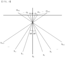
- FIGS. 6A and 6B illustrate an ideal three-dimensional ultrasound scan trajectory in a bladder scanner with a single motor according to the present invention. If the tilt angle according to manual rotation by the operator is ⁇ , scan planes as shown in FIG. 6A are obtained. In FIG. 6A , each sector-shaped scan plane is obtained by ultrasound scanning according to rotation of the ultrasound transducer by the motor. And, the set of the scan planes can be obtained by manual rotation of the operator. If the plane of the sector scan of FIG. 6B is marked with a line, a set of scan planes like that of FIG. 6A can be obtained. One line in FIG. 6B corresponds to one scan plane in FIG. 6A . It is desirable that the separation angle ⁇ of adjacent scan planes is constant.
- the separation angle ⁇ may vary for each scanning plane.
- the 3D volume image of the ultrasound image can be obtained by using the separation angle ⁇ .
- each scan plane is indicated by S i , and the number of scan planes is N+1.
- the number of scan planes is 10 to 20.
- all scan lines are assumed to come from the point 0, but this is not the case in reality. Referring to FIG. 7 while performing a sector scan using a motor mounted inside the probe of the bladder scanner, if the operator uses his hand to tilt the probe in a direction perpendicular to the sector scan, another sector scan is performed along the tilted direction.
- FIG. 7 shows a moving trajectory of the ultrasound transducer when manually tilting the bladder scanner according to the present invention.
- a sector scan is performed using a motor along the z-axis direction, and the bladder scanner is rotated by hand along the x-axis direction.
- the position of the ultrasound transducer is not fixed at point 0 but changes depending on the tilt angle ( ⁇ ). This is because, as the bladder scanner is tilted, the hemispherical lower part of the bladder scanner moves in the x-axis direction while keeping contact with the patient's abdominal surface.
- the contact point between the lower end of the bladder scanner (i.e., the lower end of the covering of the ultrasound probe) and the patient's abdominal surface is not fixed but moves in the x-axis direction. Good contact must be maintained between the lower end of the ultrasound probe and the patient's abdominal surface to prevent an air layer from forming. Otherwise, ultrasound beams are excessively reflected from the air layer, making it impossible to obtain high-quality ultrasound images.
- the position of the transducer When the operator manually tilts the bladder scanner, the position of the transducer not only moves in the x-axis (right and left) direction, but also changes in the y-axis (height) direction, as shown in FIG. 7 . This is because there must be a separation distance having certain distance between the ultrasound transducer and the probe covering for sector scan by the motor. This separation distance is usually about a few millimeters. Therefore, the position (x, y) of the transducer is not fixed and changes depending on the angle at which the operator manually tilts the probe. In this situation, if ultrasound echo signals are collected and an image is generated assuming an ideal sector scan as shown in FIG. 6 , the image will be distorted.
- the degree of image distortion is not severe, it may be difficult to recognize the distortion when viewing the ultrasound image with the naked eye.
- the estimation error can become very large. For example, if the distortion in one direction of the image is at the level of 2%, the error in volume calculation can increase to the cube of the amount of distortion, or 8%. Therefore, the actual trajectory of the ultrasound scan must be taken into account when calculating the volume of urine.
- R represents the radius of the covering at the bottom of the ultrasound probe
- ⁇ is the tilt angle of the ultrasound probe due to manual movement.
- FIG. 8 shows an actual scan trajectory in the bladder scanner according to the present invention when the bladder scanner is moved by the operator's hand.
- the scan plane considering ⁇ x and ⁇ d is as shown in FIG. 8 .
- the ultrasound scan plane does not converge to one-point 0, but changes by the Equation 6 and Equation 7 according to the tilt angle ⁇ . Since the convergence point of each sector scan plane is different, this must be taken into consideration when obtaining a 3D volume image. Through these considerations, the distortion of the ultrasound image can be eliminated and the bladder volume can be measured without error.
- FIG. 9 shows the waveform of the ultrasound echo signal received by the ultrasound transducer in the bladder scanner according to the present invention.
- the ultrasound echo signal received at a scan angle of ⁇ is denoted as S ⁇ (t).
- c is the sonic speed within the human body and is approximately 1500 m/s within the human soft tissue. Since time t and depth r have a linear relationship, the ultrasound echo signal is a function of time and depth at the same time, expressed by Equation 9.
- FIG. 10 is a coordinate in a mechanical scanning method, showing scan lines collected at an angle ⁇ . Since the scan line corresponds to polar coordinates with respect to the xy-plane, the ultrasound echo signal at the position of depth r corresponds to the ultrasound image I(x,y) in the rectangular coordinate system using Equation 10.
- FIG. 11 shows the xy coordinate system of ultrasound scanning according to mechanical rotation and the x'y' coordinate system of ultrasound scanning according to manual rotation in the ultrasound scanner according to the present invention.
- scan lines In ultrasound scanning based on mechanical rotation, scan lines converge around point 0, so the xy-plane is fixed at all angles.
- the x'y' plane moves in parallel depending on the angle. (x,y) and (x', y') can be expressed as Equations 11 to 13.
- the ultrasound echo signal obtained at the angle ⁇ using an ultrasound scanning method based on manual rotation is expressed as S ⁇ ⁇ ( r ).
Landscapes
- Health & Medical Sciences (AREA)
- Life Sciences & Earth Sciences (AREA)
- Engineering & Computer Science (AREA)
- Medical Informatics (AREA)
- Surgery (AREA)
- Pathology (AREA)
- Radiology & Medical Imaging (AREA)
- Biophysics (AREA)
- Biomedical Technology (AREA)
- Heart & Thoracic Surgery (AREA)
- Physics & Mathematics (AREA)
- Molecular Biology (AREA)
- Nuclear Medicine, Radiotherapy & Molecular Imaging (AREA)
- Animal Behavior & Ethology (AREA)
- General Health & Medical Sciences (AREA)
- Public Health (AREA)
- Veterinary Medicine (AREA)
- Computer Vision & Pattern Recognition (AREA)
- Computer Networks & Wireless Communication (AREA)
- Physiology (AREA)
- Ultra Sonic Daignosis Equipment (AREA)
Applications Claiming Priority (2)
| Application Number | Priority Date | Filing Date | Title |
|---|---|---|---|
| KR1020210186966A KR102591858B1 (ko) | 2021-12-24 | 2021-12-24 | 초음파 스캐너 및 상기 초음파 스캐너에서의 초음파 신호 보정 방법 |
| PCT/KR2021/019851 WO2023120785A1 (ko) | 2021-12-24 | 2021-12-24 | 초음파 스캐너 및 상기 초음파 스캐너에서의 초음파 신호 보정 방법 |
Publications (2)
| Publication Number | Publication Date |
|---|---|
| EP4454569A1 true EP4454569A1 (de) | 2024-10-30 |
| EP4454569A4 EP4454569A4 (de) | 2025-10-22 |
Family
ID=86903082
Family Applications (1)
| Application Number | Title | Priority Date | Filing Date |
|---|---|---|---|
| EP21969149.0A Pending EP4454569A4 (de) | 2021-12-24 | 2021-12-24 | Ultraschallscanner und ultraschallsignalkorrekturverfahren für ultraschallscanner |
Country Status (5)
| Country | Link |
|---|---|
| US (1) | US20250025125A1 (de) |
| EP (1) | EP4454569A4 (de) |
| JP (1) | JP7737184B2 (de) |
| KR (1) | KR102591858B1 (de) |
| WO (1) | WO2023120785A1 (de) |
Families Citing this family (2)
| Publication number | Priority date | Publication date | Assignee | Title |
|---|---|---|---|---|
| KR102909819B1 (ko) * | 2023-05-11 | 2026-01-08 | (주) 엠큐브테크놀로지 | 패닝 가이드 기능을 갖는 3d 초음파 스캐너 및 3d 초음파 스캔 방법 |
| CN119097314A (zh) * | 2024-09-02 | 2024-12-10 | 淮安市第二人民医院 | 一种基于深度学习的尿流动力学诊断系统 |
Family Cites Families (21)
| Publication number | Priority date | Publication date | Assignee | Title |
|---|---|---|---|---|
| JPS513602A (en) * | 1974-06-27 | 1976-01-13 | Matsushita Electric Industrial Co Ltd | Teepuseigyosochi |
| JP2714259B2 (ja) * | 1990-12-10 | 1998-02-16 | 株式会社東芝 | 超音波診断装置 |
| KR100264970B1 (ko) * | 1997-12-16 | 2001-05-02 | 이민화 | 위치검출이 가능한 초음파탐촉자 |
| US6524246B1 (en) | 2000-10-13 | 2003-02-25 | Sonocine, Inc. | Ultrasonic cellular tissue screening tool |
| JP2003093387A (ja) | 2001-09-25 | 2003-04-02 | Aloka Co Ltd | 超音波探触子及び超音波診断装置 |
| JP2003190168A (ja) * | 2001-12-28 | 2003-07-08 | Jun Koyama | 尿失禁予防システム並びにセンサーパッド設計装置及び尿失禁予防機器 |
| US6884217B2 (en) | 2003-06-27 | 2005-04-26 | Diagnostic Ultrasound Corporation | System for aiming ultrasonic bladder instruments |
| GB2391625A (en) | 2002-08-09 | 2004-02-11 | Diagnostic Ultrasound Europ B | Instantaneous ultrasonic echo measurement of bladder urine volume with a limited number of ultrasound beams |
| DE602005025799D1 (de) | 2004-12-06 | 2011-02-17 | Verathon Inc | System und verfahren zur bestimmung der organwandmasse durch dreidimensionalen ultraschall |
| KR100763453B1 (ko) | 2006-01-09 | 2007-10-08 | (주) 엠큐브테크놀로지 | 방광 진단용 초음파 진단 장치 및 초음파 진단 방법 |
| US20110137172A1 (en) * | 2006-04-25 | 2011-06-09 | Mcube Technology Co., Ltd. | Apparatus and method for measuring an amount of urine in a bladder |
| KR100779548B1 (ko) * | 2006-04-25 | 2007-11-27 | (주) 엠큐브테크놀로지 | 방광 진단용 초음파 진단 장치 및 초음파 진단 방법 |
| CA2671708A1 (en) | 2006-12-29 | 2008-07-10 | Verathon Inc. | System and method for ultrasound harmonic imaging |
| JP2010088585A (ja) * | 2008-10-06 | 2010-04-22 | Toshiba Corp | 超音波診断装置及び超音波プローブ |
| KR101263285B1 (ko) | 2011-07-21 | 2013-05-10 | (주) 엠큐브테크놀로지 | 단일 모터를 이용한 초음파 트랜스듀서 구동 장치 |
| US20140187950A1 (en) | 2012-12-31 | 2014-07-03 | General Electric Company | Ultrasound imaging system and method |
| KR102333542B1 (ko) * | 2014-11-13 | 2021-12-01 | 삼성메디슨 주식회사 | 초음파 프로브 및 그 제어 방법 |
| KR101999829B1 (ko) | 2016-04-07 | 2019-08-16 | (주)엠큐브테크놀로지 | 독립형 초음파 스캐너 |
| KR101874613B1 (ko) | 2016-07-07 | 2018-07-04 | (주)엠큐브테크놀로지 | 방광내 요량 측정 장치 및 방법 |
| KR102213449B1 (ko) * | 2019-03-06 | 2021-02-09 | (주)엠큐브테크놀로지 | 초음파 스캐너 |
| TW202110404A (zh) | 2019-09-10 | 2021-03-16 | 長庚大學 | 超音波影像系統 |
-
2021
- 2021-12-24 WO PCT/KR2021/019851 patent/WO2023120785A1/ko not_active Ceased
- 2021-12-24 JP JP2024535329A patent/JP7737184B2/ja active Active
- 2021-12-24 KR KR1020210186966A patent/KR102591858B1/ko active Active
- 2021-12-24 US US18/711,562 patent/US20250025125A1/en active Pending
- 2021-12-24 EP EP21969149.0A patent/EP4454569A4/de active Pending
Also Published As
| Publication number | Publication date |
|---|---|
| US20250025125A1 (en) | 2025-01-23 |
| JP7737184B2 (ja) | 2025-09-10 |
| JP2024546835A (ja) | 2024-12-26 |
| EP4454569A4 (de) | 2025-10-22 |
| KR102591858B1 (ko) | 2023-10-23 |
| KR20230097458A (ko) | 2023-07-03 |
| WO2023120785A1 (ko) | 2023-06-29 |
Similar Documents
| Publication | Publication Date | Title |
|---|---|---|
| JP5426169B2 (ja) | 膀胱診断用超音波診断装置及び超音波測定方法 | |
| TWI520716B (zh) | 超音波成像系統、裝置及方法 | |
| US4455872A (en) | Rotating ultrasonic scanner | |
| KR101874613B1 (ko) | 방광내 요량 측정 장치 및 방법 | |
| US20140024937A1 (en) | Apparatus and method for measuring an amount of urine in a bladder | |
| CN101820820A (zh) | 血管超声波图像测定方法 | |
| JP2001526927A (ja) | スキャニングトランスデューサ上の位置センサをキャリブレーションする方法及び装置 | |
| US20160367218A1 (en) | Apparatus and method for measuring an amount of urine in a bladder | |
| EP3515317B1 (de) | Ultraschallwandlerkachelregistrierung | |
| EP4454569A1 (de) | Ultraschallscanner und ultraschallsignalkorrekturverfahren für ultraschallscanner | |
| WO2018054969A1 (en) | Ultrasound transducer tile registration | |
| JP4697479B2 (ja) | 超音波検査ユニットまたは超音波検査装置 | |
| US20110137172A1 (en) | Apparatus and method for measuring an amount of urine in a bladder | |
| US20110218441A1 (en) | Ultrasonic diagnostic apparatus | |
| JP2001128975A (ja) | 超音波診断装置 | |
| KR102615722B1 (ko) | 초음파 스캐너 및 초음파 스캐너에서의 조준 가이드 방법 | |
| US20040249283A1 (en) | Method and apparatus for breast imaging utilizing ultrasound | |
| US8652047B2 (en) | Apparatus and method for automatically measuring the volume of urine in a bladder using ultrasound signals | |
| KR20070074288A (ko) | 방광 진단용 초음파 진단 장치 및 초음파 진단 방법 | |
| JP4555619B2 (ja) | 超音波診断装置 | |
| US20160192904A1 (en) | Apparatus and method for measuring an amount of urine in a bladder | |
| JP5222323B2 (ja) | 超音波診断装置 | |
| JPH10216127A (ja) | 超音波診断装置とその画像処理用アダプタ装置 | |
| KR20150118732A (ko) | 초음파 장치 및 그 제어 방법 | |
| JP6224341B2 (ja) | 固定具及び超音波診断装置 |
Legal Events
| Date | Code | Title | Description |
|---|---|---|---|
| STAA | Information on the status of an ep patent application or granted ep patent |
Free format text: STATUS: THE INTERNATIONAL PUBLICATION HAS BEEN MADE |
|
| PUAI | Public reference made under article 153(3) epc to a published international application that has entered the european phase |
Free format text: ORIGINAL CODE: 0009012 |
|
| STAA | Information on the status of an ep patent application or granted ep patent |
Free format text: STATUS: REQUEST FOR EXAMINATION WAS MADE |
|
| 17P | Request for examination filed |
Effective date: 20240719 |
|
| AK | Designated contracting states |
Kind code of ref document: A1 Designated state(s): AL AT BE BG CH CY CZ DE DK EE ES FI FR GB GR HR HU IE IS IT LI LT LU LV MC MK MT NL NO PL PT RO RS SE SI SK SM TR |
|
| DAV | Request for validation of the european patent (deleted) | ||
| DAX | Request for extension of the european patent (deleted) | ||
| A4 | Supplementary search report drawn up and despatched |
Effective date: 20250924 |
|
| RIC1 | Information provided on ipc code assigned before grant |
Ipc: A61B 8/14 20060101AFI20250918BHEP Ipc: A61B 8/08 20060101ALI20250918BHEP |