EP4454447A1 - Electric work vehicle - Google Patents
Electric work vehicle Download PDFInfo
- Publication number
- EP4454447A1 EP4454447A1 EP22910832.9A EP22910832A EP4454447A1 EP 4454447 A1 EP4454447 A1 EP 4454447A1 EP 22910832 A EP22910832 A EP 22910832A EP 4454447 A1 EP4454447 A1 EP 4454447A1
- Authority
- EP
- European Patent Office
- Prior art keywords
- motor
- shaft
- continuously variable
- variable transmission
- rotational power
- Prior art date
- Legal status (The legal status is an assumption and is not a legal conclusion. Google has not performed a legal analysis and makes no representation as to the accuracy of the status listed.)
- Pending
Links
Images



Classifications
-
- B—PERFORMING OPERATIONS; TRANSPORTING
- B60—VEHICLES IN GENERAL
- B60K—ARRANGEMENT OR MOUNTING OF PROPULSION UNITS OR OF TRANSMISSIONS IN VEHICLES; ARRANGEMENT OR MOUNTING OF PLURAL DIVERSE PRIME-MOVERS IN VEHICLES; AUXILIARY DRIVES FOR VEHICLES; INSTRUMENTATION OR DASHBOARDS FOR VEHICLES; ARRANGEMENTS IN CONNECTION WITH COOLING, AIR INTAKE, GAS EXHAUST OR FUEL SUPPLY OF PROPULSION UNITS IN VEHICLES
- B60K17/00—Arrangement or mounting of transmissions in vehicles
- B60K17/04—Arrangement or mounting of transmissions in vehicles characterised by arrangement, location or kind of gearing
- B60K17/10—Arrangement or mounting of transmissions in vehicles characterised by arrangement, location or kind of gearing of fluid gearing
-
- A—HUMAN NECESSITIES
- A01—AGRICULTURE; FORESTRY; ANIMAL HUSBANDRY; HUNTING; TRAPPING; FISHING
- A01B—SOIL WORKING IN AGRICULTURE OR FORESTRY; PARTS, DETAILS, OR ACCESSORIES OF AGRICULTURAL MACHINES OR IMPLEMENTS, IN GENERAL
- A01B71/00—Construction or arrangement of setting or adjusting mechanisms, of implement or tool drive or of power take-off; Means for protecting parts against dust, or the like; Adapting machine elements to or for agricultural purposes
- A01B71/02—Setting or adjusting mechanisms
-
- A—HUMAN NECESSITIES
- A01—AGRICULTURE; FORESTRY; ANIMAL HUSBANDRY; HUNTING; TRAPPING; FISHING
- A01D—HARVESTING; MOWING
- A01D34/00—Mowers; Mowing apparatus of harvesters
- A01D34/01—Mowers; Mowing apparatus of harvesters characterised by features relating to the type of cutting apparatus
- A01D34/412—Mowers; Mowing apparatus of harvesters characterised by features relating to the type of cutting apparatus having rotating cutters
- A01D34/63—Mowers; Mowing apparatus of harvesters characterised by features relating to the type of cutting apparatus having rotating cutters having cutters rotating about a vertical axis
- A01D34/64—Mowers; Mowing apparatus of harvesters characterised by features relating to the type of cutting apparatus having rotating cutters having cutters rotating about a vertical axis mounted on a vehicle, e.g. a tractor, or drawn by an animal or a vehicle
-
- B—PERFORMING OPERATIONS; TRANSPORTING
- B60—VEHICLES IN GENERAL
- B60K—ARRANGEMENT OR MOUNTING OF PROPULSION UNITS OR OF TRANSMISSIONS IN VEHICLES; ARRANGEMENT OR MOUNTING OF PLURAL DIVERSE PRIME-MOVERS IN VEHICLES; AUXILIARY DRIVES FOR VEHICLES; INSTRUMENTATION OR DASHBOARDS FOR VEHICLES; ARRANGEMENTS IN CONNECTION WITH COOLING, AIR INTAKE, GAS EXHAUST OR FUEL SUPPLY OF PROPULSION UNITS IN VEHICLES
- B60K17/00—Arrangement or mounting of transmissions in vehicles
- B60K17/22—Arrangement or mounting of transmissions in vehicles characterised by arrangement, location, or type of main drive shafting, e.g. cardan shaft
-
- B—PERFORMING OPERATIONS; TRANSPORTING
- B60—VEHICLES IN GENERAL
- B60K—ARRANGEMENT OR MOUNTING OF PROPULSION UNITS OR OF TRANSMISSIONS IN VEHICLES; ARRANGEMENT OR MOUNTING OF PLURAL DIVERSE PRIME-MOVERS IN VEHICLES; AUXILIARY DRIVES FOR VEHICLES; INSTRUMENTATION OR DASHBOARDS FOR VEHICLES; ARRANGEMENTS IN CONNECTION WITH COOLING, AIR INTAKE, GAS EXHAUST OR FUEL SUPPLY OF PROPULSION UNITS IN VEHICLES
- B60K17/00—Arrangement or mounting of transmissions in vehicles
- B60K17/28—Arrangement or mounting of transmissions in vehicles characterised by arrangement, location, or type of power take-off
-
- B—PERFORMING OPERATIONS; TRANSPORTING
- B60—VEHICLES IN GENERAL
- B60L—PROPULSION OF ELECTRICALLY-PROPELLED VEHICLES; SUPPLYING ELECTRIC POWER FOR AUXILIARY EQUIPMENT OF ELECTRICALLY-PROPELLED VEHICLES; ELECTRODYNAMIC BRAKE SYSTEMS FOR VEHICLES IN GENERAL; MAGNETIC SUSPENSION OR LEVITATION FOR VEHICLES; MONITORING OPERATING VARIABLES OF ELECTRICALLY-PROPELLED VEHICLES; ELECTRIC SAFETY DEVICES FOR ELECTRICALLY-PROPELLED VEHICLES
- B60L15/00—Methods, circuits, or devices for controlling the traction-motor speed of electrically-propelled vehicles
-
- B—PERFORMING OPERATIONS; TRANSPORTING
- B60—VEHICLES IN GENERAL
- B60L—PROPULSION OF ELECTRICALLY-PROPELLED VEHICLES; SUPPLYING ELECTRIC POWER FOR AUXILIARY EQUIPMENT OF ELECTRICALLY-PROPELLED VEHICLES; ELECTRODYNAMIC BRAKE SYSTEMS FOR VEHICLES IN GENERAL; MAGNETIC SUSPENSION OR LEVITATION FOR VEHICLES; MONITORING OPERATING VARIABLES OF ELECTRICALLY-PROPELLED VEHICLES; ELECTRIC SAFETY DEVICES FOR ELECTRICALLY-PROPELLED VEHICLES
- B60L15/00—Methods, circuits, or devices for controlling the traction-motor speed of electrically-propelled vehicles
- B60L15/20—Methods, circuits, or devices for controlling the traction-motor speed of electrically-propelled vehicles for control of the vehicle or its driving motor to achieve a desired performance, e.g. speed, torque, programmed variation of speed
-
- B—PERFORMING OPERATIONS; TRANSPORTING
- B60—VEHICLES IN GENERAL
- B60L—PROPULSION OF ELECTRICALLY-PROPELLED VEHICLES; SUPPLYING ELECTRIC POWER FOR AUXILIARY EQUIPMENT OF ELECTRICALLY-PROPELLED VEHICLES; ELECTRODYNAMIC BRAKE SYSTEMS FOR VEHICLES IN GENERAL; MAGNETIC SUSPENSION OR LEVITATION FOR VEHICLES; MONITORING OPERATING VARIABLES OF ELECTRICALLY-PROPELLED VEHICLES; ELECTRIC SAFETY DEVICES FOR ELECTRICALLY-PROPELLED VEHICLES
- B60L50/00—Electric propulsion with power supplied within the vehicle
- B60L50/50—Electric propulsion with power supplied within the vehicle using propulsion power supplied by batteries or fuel cells
- B60L50/60—Electric propulsion with power supplied within the vehicle using propulsion power supplied by batteries or fuel cells using power supplied by batteries
-
- B—PERFORMING OPERATIONS; TRANSPORTING
- B60—VEHICLES IN GENERAL
- B60W—CONJOINT CONTROL OF VEHICLE SUB-UNITS OF DIFFERENT TYPE OR DIFFERENT FUNCTION; CONTROL SYSTEMS SPECIALLY ADAPTED FOR HYBRID VEHICLES; ROAD VEHICLE DRIVE CONTROL SYSTEMS FOR PURPOSES NOT RELATED TO THE CONTROL OF A PARTICULAR SUB-UNIT
- B60W10/00—Conjoint control of vehicle sub-units of different type or different function
- B60W10/04—Conjoint control of vehicle sub-units of different type or different function including control of propulsion units
- B60W10/08—Conjoint control of vehicle sub-units of different type or different function including control of propulsion units including control of electric propulsion units, e.g. motors or generators
-
- F—MECHANICAL ENGINEERING; LIGHTING; HEATING; WEAPONS; BLASTING
- F16—ENGINEERING ELEMENTS AND UNITS; GENERAL MEASURES FOR PRODUCING AND MAINTAINING EFFECTIVE FUNCTIONING OF MACHINES OR INSTALLATIONS; THERMAL INSULATION IN GENERAL
- F16H—GEARING
- F16H47/00—Combinations of mechanical gearing with fluid clutches or fluid gearing
- F16H47/02—Combinations of mechanical gearing with fluid clutches or fluid gearing the fluid gearing being of the volumetric type
-
- H—ELECTRICITY
- H02—GENERATION; CONVERSION OR DISTRIBUTION OF ELECTRIC POWER
- H02M—APPARATUS FOR CONVERSION BETWEEN AC AND AC, BETWEEN AC AND DC, OR BETWEEN DC AND DC, AND FOR USE WITH MAINS OR SIMILAR POWER SUPPLY SYSTEMS; CONVERSION OF DC OR AC INPUT POWER INTO SURGE OUTPUT POWER; CONTROL OR REGULATION THEREOF
- H02M7/00—Conversion of AC power input into DC power output; Conversion of DC power input into AC power output
- H02M7/42—Conversion of DC power input into AC power output without possibility of reversal
- H02M7/44—Conversion of DC power input into AC power output without possibility of reversal by static converters
- H02M7/48—Conversion of DC power input into AC power output without possibility of reversal by static converters using discharge tubes with control electrode or semiconductor devices with control electrode
-
- B—PERFORMING OPERATIONS; TRANSPORTING
- B60—VEHICLES IN GENERAL
- B60W—CONJOINT CONTROL OF VEHICLE SUB-UNITS OF DIFFERENT TYPE OR DIFFERENT FUNCTION; CONTROL SYSTEMS SPECIALLY ADAPTED FOR HYBRID VEHICLES; ROAD VEHICLE DRIVE CONTROL SYSTEMS FOR PURPOSES NOT RELATED TO THE CONTROL OF A PARTICULAR SUB-UNIT
- B60W2710/00—Output or target parameters relating to a particular sub-units
- B60W2710/08—Electric propulsion units
- B60W2710/083—Torque
-
- B—PERFORMING OPERATIONS; TRANSPORTING
- B60—VEHICLES IN GENERAL
- B60Y—INDEXING SCHEME RELATING TO ASPECTS CROSS-CUTTING VEHICLE TECHNOLOGY
- B60Y2200/00—Type of vehicle
- B60Y2200/20—Off-Road Vehicles
- B60Y2200/22—Agricultural vehicles
- B60Y2200/221—Tractors
-
- B—PERFORMING OPERATIONS; TRANSPORTING
- B60—VEHICLES IN GENERAL
- B60Y—INDEXING SCHEME RELATING TO ASPECTS CROSS-CUTTING VEHICLE TECHNOLOGY
- B60Y2200/00—Type of vehicle
- B60Y2200/90—Vehicles comprising electric prime movers
- B60Y2200/91—Electric vehicles
-
- Y—GENERAL TAGGING OF NEW TECHNOLOGICAL DEVELOPMENTS; GENERAL TAGGING OF CROSS-SECTIONAL TECHNOLOGIES SPANNING OVER SEVERAL SECTIONS OF THE IPC; TECHNICAL SUBJECTS COVERED BY FORMER USPC CROSS-REFERENCE ART COLLECTIONS [XRACs] AND DIGESTS
- Y02—TECHNOLOGIES OR APPLICATIONS FOR MITIGATION OR ADAPTATION AGAINST CLIMATE CHANGE
- Y02T—CLIMATE CHANGE MITIGATION TECHNOLOGIES RELATED TO TRANSPORTATION
- Y02T10/00—Road transport of goods or passengers
- Y02T10/60—Other road transportation technologies with climate change mitigation effect
- Y02T10/72—Electric energy management in electromobility
Definitions
- the present invention relates to an electric work vehicle that includes a battery, a motor driven by electric power supplied from the battery, and a travel device driven by rotational power output from the motor.
- Patent Document 1 A known example of an electric work vehicle such as that described above is disclosed in Patent Document 1, for example.
- this electric work vehicle (“tractor” in Patent Document 1)
- part of the output of the motor is transmitted to a work device ("tilling device” in Patent Document 1).
- the work device is driven in this way.
- Patent Document 1 JP 2021-957A
- Patent Document 1 The power transmission structure that transmits output from the motor to the work device is not described in detail in Patent Document 1.
- the electric work vehicle described in Patent Document 1 can conceivably be provided with a power take-off shaft that can be connected to the work device and can transmit rotational power from the motor to the work device. With this configuration, the work device can be driven by connecting the work device to the power take-off shaft.
- the rotation speed of the power take-off shaft may also change.
- An object of the present invention is to provide an electric work vehicle that enables changing the vehicle speed while maintaining the rotation speed of the power take-off shaft at a target rotation speed.
- One aspect of the present invention is an electric work vehicle including: a battery; a motor configured to be driven with electric power supplied from the battery; a travel device configured to be driven with rotational power output from the motor; a motor control section configured to control the motor; a power take-off shaft connectable to a work device and configured to transmit the rotational power from the motor to the work device; and a distribution mechanism configured to distribute the rotational power output from the motor to a hydraulic continuously variable transmission and the power take-off shaft, the hydraulic continuously variable transmission being configured to change a speed of the rotational power input to the hydraulic continuously variable transmission, and output resulting rotational power to the travel device, the motor control section being further configured to execute maintenance control to maintain an output rotation speed of the motor at a rotation speed corresponding to a target rotation speed of the power take-off shaft, and the hydraulic continuously variable transmission having a transmission state changeable according to manual operation of a speed change operation tool while the maintenance control is executed.
- the speed change operation tool if the speed change operation tool is manually operated while maintenance control is being executed, the speed of the rotational power output from the hydraulic continuously variable transmission to the travel device changes while maintaining the rotation speed of the power take-off shaft at the target rotation speed. As a result, the vehicle speed changes.
- the hydraulic continuously variable transmission includes a relief mechanism.
- the hydraulic continuously variable transmission outputs forward rotational power or reverse rotational power to the travel device according to manual operation of the speed change operation tool, the electric work vehicle travels forward while the travel device is driven by the forward rotational power, and the electric work vehicle travels backward while the travel device is driven by the reverse rotational power.
- an electric work vehicle that can travel forward and backward without provision of a dedicated mechanism for reversing rotation of the travel device in addition to the hydraulic continuously variable transmission.
- an electric work vehicle that can travel forward and backward can be realized with a relatively simple configuration.
- the electric work vehicle further includes a rotation operation tool configured to accept an operation to change a rotation state of the power take-off shaft, wherein in a case where (i) the hydraulic continuously variable transmission is in a transmission state in which rotational power is not output from the hydraulic continuously variable transmission, and (ii) the rotation operation tool has been operated in such a manner that the power take-off shaft does not rotate, the motor control section executes reduction control to reduce an output torque of the motor.
- a rotation operation tool configured to accept an operation to change a rotation state of the power take-off shaft, wherein in a case where (i) the hydraulic continuously variable transmission is in a transmission state in which rotational power is not output from the hydraulic continuously variable transmission, and (ii) the rotation operation tool has been operated in such a manner that the power take-off shaft does not rotate, the motor control section executes reduction control to reduce an output torque of the motor.
- the power take-off shaft is a front power take-off shaft provided in a front section of a body of the electric work vehicle.
- the motive power from the motor can be extracted by the front power take-off shaft, thus making it easy to transmit motive power from the motor to a work device such as a front mower or a snow removal device that is coupled to a front section of the body of the electric work vehicle.
- the tractor includes left and right front wheels 10, left and right rear wheels 11, and a cover member 12.
- the tractor also includes a body frame 2 and a driving section 3.
- the body frame 2 is supported by the left and right front wheels 10 and the left and right rear wheels 11.
- the cover member 12 is disposed in a front portion of the body of the tractor.
- the driving section 3 is behind the cover member 12. In other words, the cover member 12 is in front of the driving section 3.
- the driving section 3 includes a protective frame 30, a driver's seat 31, and a steering wheel 32.
- An operator can sit on the driver's seat 31. Accordingly, the operator can get on the driving section 3.
- the operator steers the left and right front wheels 10 by operating the steering wheel 32.
- the operator can perform various driving operations in the driving section 3.
- the tractor includes a battery 4 for traveling.
- the cover member 12 is configured to be pivotable about an opening/closing axis Q extending in the left-right direction of the body. Accordingly, the cover member 12 is configured to be openable and closable. When the cover member 12 is closed, the battery 4 for traveling is covered by the cover member 12.
- the tractor includes an inverter 14 and a motor M.
- the battery 4 for traveling supplies electric power to the inverter 14.
- the inverter 14 converts DC power supplied from the battery 4 for traveling to AC power, and supplies the AC power to the motor M.
- the motor M is driven by the AC power supplied from the inverter 14.
- the tractor includes a hydraulic continuously variable transmission 15 and a transmission 16.
- the hydraulic continuously variable transmission 15 includes a hydraulic pump 15a and a hydraulic motor 15b.
- the hydraulic pump 15a is driven by rotational power received from the motor M. As a result of the hydraulic pump 15a being driven, rotational power is output from the hydraulic motor 15b.
- the hydraulic continuously variable transmission 15 is configured to change the speed of rotational power between the hydraulic pump 15a and the hydraulic motor 15b. Also, the hydraulic continuously variable transmission 15 is configured to be capable of changing the transmission ratio in a stepless manner.
- the rotational power output from the hydraulic motor 15b is transmitted to the transmission 16.
- the speed of the rotational power transmitted to the transmission 16 is changed by a gear transmission mechanism included in the transmission 16, and the resulting rotational power is distributed to the left and right front wheels 10 and the left and right rear wheels 11.
- the left and right front wheels 10 and the left and right rear wheels 11 are driven in this way.
- the tractor includes a mid PTO shaft 17 and a rear PTO shaft 18.
- the rotational power output from the motor M is distributed to the hydraulic pump 15a, the mid PTO shaft 17, and the rear PTO shaft 18.
- the mid PTO shaft 17 and the rear PTO shaft 18 thus rotate.
- a work device is connected to the mid PTO shaft 17 or the rear PTO shaft 18, the work device is driven by rotational power from the mid PTO shaft 17 or the rear PTO shaft 18.
- a mowing device 19 is connected to the mid PTO shaft 17. The mowing device 19 is driven by rotational power from the mid PTO shaft 17.
- the tractor of the present embodiment includes the battery 4 for traveling, the motor M driven by electric power supplied from the battery 4 for traveling, and the left and right front wheels 10 and the left and right rear wheels 11 that are driven by rotational power output from the motor M.
- this tractor includes the mid PTO shaft 17 and the rear PTO shaft 18 that can each be connected to a work device and can transmit rotational power from the motor M to the work device.
- the hydraulic continuously variable transmission 15 changes the speed of the rotational power input to the hydraulic continuously variable transmission 15, and outputs the resulting rotational power to the left and right front wheels 10 and the left and right rear wheels 11.
- this tractor corresponds to an "electric work vehicle” according to the present invention.
- the battery 4 for traveling corresponds to a “battery” according to the present invention.
- the left and right front wheels 10 and the left and right rear wheels 11 both correspond to a “travel device” according to the present invention.
- the mid PTO shaft 17 and the rear PTO shaft 18 both correspond to a "power take-off shaft” according to the present invention.
- the mowing device 19 corresponds to a "work device” according to the present invention.
- the tractor includes a distribution mechanism 20.
- the distribution mechanism 20 includes a power transmission shaft MB, a first shaft 21, a first gear mechanism 22, a second gear mechanism 23, a second shaft 24, a third gear mechanism 25, a first clutch 26, and a second clutch 27.
- the first clutch 26 and the second clutch 27 can both be changed between an engaged state in which motive power is transmitted and a disengaged state in which motive power is not transmitted.
- An output shaft MA of the motor M is connected to the first shaft 21 via the power transmission shaft MB.
- the output shaft MA, the power transmission shaft MB, and the first shaft 21 rotate integrally.
- the first shaft 21 is coupled to the hydraulic pump 15a.
- rotational power output from the motor M is distributed from the first shaft 21 to the hydraulic pump 15a, the first gear mechanism 22, and the second shaft 24.
- the rotational power transmitted to the first gear mechanism 22 is transmitted to the mid PTO shaft 17 via the second gear mechanism 23.
- the mid PTO shaft 17 thus rotates.
- the rotational power transmitted to the second shaft 24 is transmitted to the rear PTO shaft 18 via the third gear mechanism 25.
- the rear PTO shaft 18 thus rotates.
- the tractor of the present embodiment includes the distribution mechanism 20 that distributes the rotational power output from the motor M to the hydraulic continuously variable transmission 15, the mid PTO shaft 17, and the rear PTO shaft 18.
- the mid PTO shaft 17 rotates if the first clutch 26 is in the engaged state, whereas the mid PTO shaft 17 does not rotate if the first clutch 26 is in the disengaged state.
- the rear PTO shaft 18 rotates if the second clutch 27 is in the engaged state, whereas the rear PTO shaft 18 does not rotate if the second clutch 27 is in the disengaged state.
- the speed of the rotational power transmitted to the hydraulic pump 15a is changed via hydraulic pressure in the hydraulic continuously variable transmission 15, and the resulting rotational power is output from the hydraulic motor 15b.
- the rotational power output from the hydraulic motor 15b is transmitted via a third shaft 41 to a transmission section 16a, which is a gear transmission mechanism included in the transmission 16.
- the speed of the rotational power transmitted to the transmission section 16a is changed by the transmission section 16a, and the resulting rotational power is distributed to a power transmission shaft X and a rear wheel differential mechanism 43.
- the rotational power transmitted to the power transmission shaft X is transmitted to the left and right front wheels 10 via a transmission connection section Z and a power transmission shaft Y.
- the left and right front wheels 10 are thus driven.
- the left and right rear wheels 11 are driven by rotational power transmitted to the rear wheel differential mechanism 43.
- the power transmission shaft X extends diagonally forward so as to pass between cases W coupled to the hydraulic continuously variable transmission 15 and transmit motive power from the transmission 16.
- a front wheel input section 10A to which motive power for the left and right front wheels 10 is input, is arranged at a position lower than the upper end of the power transmission shaft X in the power transmission direction.
- the motor M and the hydraulic continuously variable transmission 15 are arranged at positions spaced apart from each other and connecting them to each other with the power transmission shaft MB, resonant vibration is less likely to occur.
- the inverter 14 is susceptible to vibration, a structure is employed in which the inverter 14 is connected to the body frame 2, and the battery 4 for traveling is arranged above the inverter 14, thus suppressing vibration in the vicinity of the inverter 14. Also, the inverter 14 is spaced apart from the hydraulic continuously variable transmission 15 to prevent problems caused by vibration.
- a radiator 80, a DC-DC (Direct Current - Direct Current) converter 81, and an auxiliary battery 82 are arranged in front of the battery 4 for traveling.
- the radiator 80 and a water pump (not shown) are included in a cooling water path in the tractor. When the water pump pumps cooling water, the cooling water circulates through the cooling water path. The cooling water is cooled by passing through the radiator 80.
- the DC-DC converter 81 steps down the voltage of the power from the battery 4 for traveling and supplies the resulting power to the auxiliary battery 82.
- the auxiliary battery 82 supplies electric power to various auxiliary devices.
- the tractor includes an accelerator operation tool 51, a rotation operation tool 52, a speed change operation tool 53, and a control section 54.
- the accelerator operation tool 51, the rotation operation tool 52, and the speed change operation tool 53 may be levers or buttons, for example, but are not particularly limited to this.
- the accelerator operation tool 51, the rotation operation tool 52, and the speed change operation tool 53 may be provided in the driving section 3, for example.
- the control section 54 includes a motor control section 55, a work clutch control section 56, and a speed change control section 57.
- the motor control section 55 controls the output rotation speed of motor M by controlling the inverter 14 based on the signal. In other words, the motor control section 55 controls the output rotation speed of the motor M in accordance with a manual operation performed on the accelerator operation tool 51. Also, the accelerator operation tool 51 accepts an operation for changing the output rotation speed of the motor M.
- the tractor of the present embodiment includes the motor control section 55 that controls the motor M.
- the work clutch control section 56 controls the engaged/disengaged states of the first clutch 26 and the second clutch 27 based on the signal.
- the work clutch control section 56 thereby controls the rotation states of the mid PTO shaft 17 and the rear PTO shaft 18. More specifically, the work clutch control section 56 switches the states of the mid PTO shaft 17 and the rear PTO shaft 18 between a rotating state and a non-rotating state.
- the work clutch control section 56 controls the rotation states of the mid PTO shaft 17 and the rear PTO shaft 18 in accordance with a manual operation performed on the rotation operation tool 52. Also, the rotation operation tool 52 accepts an operation for changing the rotation state of the mid PTO shaft 17 and the rear PTO shaft 18.
- the tractor of the present embodiment includes the rotation operation tool 52 that accepts an operation for changing the rotation state of the mid PTO shaft 17 and the rear PTO shaft 18.
- the speed change control section 57 controls the angle of a pump swash plate 58 of the hydraulic pump 15a based on the signal.
- the speed change control section 57 controls the transmission state of the hydraulic continuously variable transmission 15 in accordance with a manual operation performed on the speed change operation tool 53.
- the speed change operation tool 53 accepts an operation for changing the transmission state of the hydraulic continuously variable transmission 15.
- the hydraulic continuously variable transmission 15 is configured such that when the pump swash plate 58 is in a neutral state, rotational power is not output from the hydraulic motor 15b. Furthermore, the hydraulic continuously variable transmission 15 is configured such that rotational power in the forward direction and the reverse direction can be output to the left and right front wheels 10 and the left and right rear wheels 11 in accordance with the angle of the pump swash plate 58. In other words, the hydraulic continuously variable transmission 15 is configured such that rotational power in the forward direction and the reverse direction can be output to the left and right front wheels 10 and the left and right rear wheels 11 in accordance with a manual operation performed on the speed change operation tool 53.
- the tractor of the present embodiment can travel forward by driving the left and right front wheels 10 and the left and right rear wheels 11 with forward rotational power. Also, the tractor of the present embodiment can travel backward by driving the left and right front wheels 10 and the left and right rear wheels 11 with reverse rotational power.
- the operator When the tractor of the present embodiment is to perform work while traveling, the operator operates the accelerator operation tool 51 to set the output rotation speed of the motor M to a rotation speed that corresponds to a target rotation speed of the mid PTO shaft 17 or the rear PTO shaft 18.
- the motor control section 55 is able to maintain the output rotation speed of the motor M at the rotation speed set by the manual operation performed on the accelerator operation tool 51 while the tractor is performing work and traveling.
- the motor control section 55 can perform maintenance control for maintaining the output rotation speed of the motor M at a rotation speed that corresponds to a target rotation speed of the mid PTO shaft 17 or the rear PTO shaft 18.
- the transmission state of the hydraulic continuously variable transmission 15 can be changed by manually operating the speed change operation tool 53. Accordingly, it is possible to change the vehicle speed while maintaining the rotation speed of the mid PTO shaft 17 or the rear PTO shaft 18.
- the transmission state of the hydraulic continuously variable transmission 15 can be changed in accordance with a manual operation performed on the speed change operation tool 53 while maintenance control is being executed.
- control section 54 and the motor control section 55 included in the control section 54 may be a physical device such as a microcomputer, or may be a functional unit in software.
- the hydraulic continuously variable transmission 15 includes a hydraulic circuit 60.
- the hydraulic pump 15a and the hydraulic motor 15b are included in the hydraulic circuit 60.
- the hydraulic continuously variable transmission 15 includes an oil pump 61 and a relief mechanism 62.
- the oil pump 61 is coupled to the first shaft 21.
- the oil pump 61 is configured to be driven by rotational power from the first shaft 21.
- the oil pump 61 supplies oil (hydraulic oil) to the hydraulic circuit 60.
- the oil pump 61 may be provided outside the hydraulic continuously variable transmission 15. Also, the oil pump 61 may be configured to be driven by rotational power from a member other than the first shaft 21.
- the relief mechanism 62 is connected to the hydraulic circuit 60.
- the relief mechanism 62 is a mechanism that discharges oil (hydraulic oil) in the hydraulic circuit 60 to the outside of the hydraulic circuit 60 in the case where the hydraulic pressure in the hydraulic circuit 60 exceeds a predetermined threshold value. According to this configuration, when the hydraulic pressure in the hydraulic circuit 60 exceeds the predetermined threshold, oil is discharged from the hydraulic circuit 60 via the relief mechanism 62. In this way, the hydraulic continuously variable transmission 15 has the relief mechanism 62.
- the motor control section 55 shown in FIG. 6 is configured to execute reduction control in the case where the hydraulic continuously variable transmission 15 is in a transmission state in which rotational power is not output from the hydraulic continuously variable transmission 15 and furthermore the rotation operation tool 52 has been operated such that the mid PTO shaft 17 and the rear PTO shaft 18 do not rotate.
- the reduction control is control for reducing the output torque of the motor M. Also, in the present embodiment, the driving of the motor M is stopped in the reduction control.
- the motor control section 55 executes reduction control for reducing the output torque of the motor M in the case where the hydraulic continuously variable transmission 15 is in a transmission state in which rotational power is not output from the hydraulic continuously variable transmission 15 and furthermore the rotation operation tool 52 has been operated such that the mid PTO shaft 17 and the rear PTO shaft 18 do not rotate.
- the reduction control will be described below.
- the motor control section 55 executes the reduction control in accordance with the reduction control flow shown in FIG. 8 . This reduction control flow is repeatedly executed at regular intervals while the motor M is driven to rotate.
- step S01 As shown in FIG. 6 , information indicating the operation state of the rotation operation tool 52 is transmitted from the rotation operation tool 52 to the motor control section 55. Based on the information, the motor control section 55 determines whether or not the rotation operation tool 52 has been operated such that the mid PTO shaft 17 and the rear PTO shaft 18 do not rotate.
- step S02 If the rotation operation tool 52 has been operated such that the mid PTO shaft 17 and the rear PTO shaft 18 do not rotate ("Yes" in step S01 of FIG. 8 ), the processing moves to step S02.
- step S02 information indicating the operation state of the speed change operation tool 53 is transmitted from the speed change operation tool 53 to the motor control section 55. Based on the information, the motor control section 55 determines whether or not the hydraulic continuously variable transmission 15 is in a transmission state in which rotational power is not output from the hydraulic continuously variable transmission 15. More specifically, the motor control section 55 determines whether or not the pump swash plate 58 is in the neutral state.
- step S03 If the pump swash plate 58 is in the neutral state ("Yes" in step S02 of FIG. 8 ), the processing moves to step S03.
- step S03 the above-described reduction control is executed by the motor control section 55.
- the reduction control flow then ends.
- the present invention is not particularly limited to this, a configuration is possible in which after the reduction control is executed, the output torque of the motor M is returned to the original value when the hydraulic continuously variable transmission 15 enters a transmission state in which rotational power is output from the hydraulic continuously variable transmission 15, or the output torque of the motor M is returned to the original value when the rotation operation tool 52 is operated such that the mid PTO shaft 17 or the rear PTO shaft 18 rotates, for example.
- returning the output torque to the original value means returning the output torque to the value before execution of the reduction control.
- the speed change operation tool 53 if the speed change operation tool 53 is manually operated while maintenance control is being executed, the speed of the rotational power output from the hydraulic continuously variable transmission 15 to the left and right front wheels 10 and the left and right rear wheels 11 changes while the rotation speed of the mid PTO shaft 17 or the rear PTO shaft 18 is maintained at the target rotation speed. As a result, the vehicle speed changes.
- the hydraulic continuously variable transmission 15 is provided.
- a travel clutch 72 is provided in place of the hydraulic continuously variable transmission 15. Also, in the first alternative embodiment, a travel clutch operation tool 70 and a travel clutch control section 71 are provided in place of the speed change operation tool 53 and the speed change control section 57.
- the travel clutch operation tool 70 may be a lever or a button, for example, but is not particularly limited to this. Furthermore, the travel clutch operation tool 70 may be provided in the driving section 3, for example.
- the travel clutch 72 can be changed between an engaged state in which power is transmitted and a disengaged state in which power is not transmitted.
- the power transmission mechanism of the first alternative embodiment is configured such that when the travel clutch 72 is in the engaged state, rotational power is transmitted from the first shaft 21 to the third shaft 41 via the travel clutch 72. When the travel clutch 72 is in the disengaged state, rotational power from the motor M is not transmitted to the left and right front wheels 10 and the left and right rear wheels 11.
- the travel clutch control section 71 controls the engaged/disengaged state of the travel clutch 72 based on the signal. In other words, the travel clutch control section 71 controls the engaged/disengaged state of the travel clutch 72 in accordance with a manual operation performed on the travel clutch operation tool 70.
- the motor control section 55 executes the above-described reduction control in the case where the travel clutch 72 is in the disengaged state and furthermore the rotation operation tool 52 has been operated such that the mid PTO shaft 17 and the rear PTO shaft 18 do not rotate.
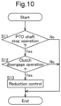
- the motor control section 55 of the first alternative embodiment executes the reduction control in accordance with the reduction control flow shown in FIG. 10 .
- This reduction control flow is repeatedly executed at regular intervals while the motor M is driven to rotate.
- step S11 When the reduction control flow is started, first, the processing of step S11 is executed. In step S11, similarly to step S01 in FIG. 8 , it is determined whether or not the rotation operation tool 52 has been operated such that the mid PTO shaft 17 and the rear PTO shaft 18 do not rotate.
- step S12 If the rotation operation tool 52 has been operated such that the mid PTO shaft 17 and the rear PTO shaft 18 do not rotate ("Yes" in step S11 of FIG. 10 ), the processing moves to step S12.
- step S12 information indicating the operation state of the travel clutch operation tool 70 is transmitted from the travel clutch operation tool 70 to the motor control section 55. Based on the information, the motor control section 55 determines whether or not the travel clutch 72 is in the disengaged state.
- step S13 If the travel clutch 72 is in the disengaged state ("Yes" in step S12 of FIG. 10 ), the processing moves to step S13.
- step S13 the motor control section 55 executes the above-described reduction control.
- the reduction control flow then ends.
- the first front PTO shaft 91 is rotatably supported by a first support section 92 provided in a front section of the body frame 2.
- a rear section of the first front PTO shaft 91 is coupled to an output section M2 of the motor M via a rotation shaft 93.
- the rotation shaft 93 is rotatably supported by a second support section 94 of the body frame 2, between the first support section 92 and the output section M2.
- Motive power generated by the motor M and output from the output section M2 is transmitted to the first front PTO shaft 91 via the rotation shaft 93.
- the first front PTO shaft 91 can be connected to the work device and can transmit rotational power from the motor M to the work device. Also, according to a configuration similar to that of the above embodiment, the motor control section 55 can execute maintenance control for maintaining the output rotation speed of the motor M at a rotation speed corresponding to the target rotation speed of the first front PTO shaft 91. Furthermore, according to a configuration similar to that of the above embodiment, the rotation operation tool 52 accepts an operation for changing the rotation state of the first front PTO shaft 91.
- the motor control section 55 executes the reduction control for reducing the output torque of the motor M in the case where the hydraulic continuously variable transmission 15 is in a transmission state in which rotational power is not output from the hydraulic continuously variable transmission 15 and furthermore the rotation operation tool 52 has been operated such that the mid PTO shaft 17, the rear PTO shaft 18, and the first front PTO shaft 91 do not rotate.
- the output section M2 is included in the previously described distribution mechanism 20.
- the distribution mechanism 20 distributes the rotational power output from the motor M to the hydraulic continuously variable transmission 15, the mid PTO shaft 17, the rear PTO shaft 18, and the first front PTO shaft 91.
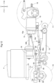
- the tractor may be configured as shown in FIG. 12 .
- a second front PTO shaft 95 (corresponding to a "power take-off shaft” and a “front power take-off shaft” according to the present invention) is provided in a front section of the tractor body.
- the second front PTO shaft 95 extracts motive power from the motor M.
- the second front PTO shaft 95 is rotatably supported by a first support section 92 provided in a front section of the body frame 2.
- a rear section of the second front PTO shaft 95 is coupled to a power take-off section 96a, which is provided in an input case 96 of the mowing device 19, via a rotation shaft 97.
- the rotation shaft 97 is rotatably supported by a second support section 94 of the body frame 2, between the first support section 92 and the power take-off section 96a.
- a universal joint 98 which serves as a bending section that allows raising and lowering of the mowing device 19, is provided on the rotation shaft 97 at a portion between the second support section 94 and the power take-off section 96a.
- Motive power output by the motor M is transmitted to the second front PTO shaft 95 via the mid PTO shaft 17, the input case 96, and the rotation shaft 97.
- the second front PTO shaft 95 can be connected to the work device and can transmit rotational power from the motor M to the work device.
- the motor control section 55 can execute maintenance control for maintaining the output rotation speed of the motor M at a rotation speed corresponding to the target rotation speed of the second front PTO shaft 95.
- the rotation operation tool 52 accepts an operation for changing the rotation state of the second front PTO shaft 95.
- the motor control section 55 executes the reduction control for reducing the output torque of the motor M in the case where the hydraulic continuously variable transmission 15 is in a transmission state in which rotational power is not output from the hydraulic continuously variable transmission 15 and furthermore the rotation operation tool 52 has been operated such that the mid PTO shaft 17, the rear PTO shaft 18, and the second front PTO shaft 95 do not rotate.
- the distribution mechanism 20 distributes the rotational power output from the motor M to the hydraulic continuously variable transmission 15, to the mid PTO shaft 17 and the second front PTO shaft 95, and to the rear PTO shaft 18.
- the second front PTO shaft 95 is located downstream of the mid PTO shaft 17 in the flow of motive power transmission.
- the present invention is applicable to not only a tractor but also various electric work vehicles such as a combine, a rice transplanter, and a construction machine.
Landscapes
- Engineering & Computer Science (AREA)
- Mechanical Engineering (AREA)
- Transportation (AREA)
- Chemical & Material Sciences (AREA)
- Combustion & Propulsion (AREA)
- Power Engineering (AREA)
- Life Sciences & Earth Sciences (AREA)
- Environmental Sciences (AREA)
- General Engineering & Computer Science (AREA)
- Sustainable Development (AREA)
- Soil Sciences (AREA)
- Sustainable Energy (AREA)
- Arrangement And Driving Of Transmission Devices (AREA)
- Agricultural Machines (AREA)
- Harvester Elements (AREA)
- Motor Power Transmission Devices (AREA)
- Electric Propulsion And Braking For Vehicles (AREA)
- Inverter Devices (AREA)
Abstract
Description
- The present invention relates to an electric work vehicle that includes a battery, a motor driven by electric power supplied from the battery, and a travel device driven by rotational power output from the motor.
- A known example of an electric work vehicle such as that described above is disclosed in
Patent Document 1, for example. In this electric work vehicle ("tractor" in Patent Document 1), part of the output of the motor is transmitted to a work device ("tilling device" in Patent Document 1). The work device is driven in this way. - Patent Document 1:
JP 2021-957A - The power transmission structure that transmits output from the motor to the work device is not described in detail in
Patent Document 1. Here, the electric work vehicle described inPatent Document 1 can conceivably be provided with a power take-off shaft that can be connected to the work device and can transmit rotational power from the motor to the work device. With this configuration, the work device can be driven by connecting the work device to the power take-off shaft. - However, depending on the configuration of the power transmission structure that transmits the output from the motor to the work device, when the speed of the rotational power transmitted to the travel device is changed in order to change the vehicle speed, the rotation speed of the power take-off shaft may also change.
- An object of the present invention is to provide an electric work vehicle that enables changing the vehicle speed while maintaining the rotation speed of the power take-off shaft at a target rotation speed.
- One aspect of the present invention is an electric work vehicle including: a battery; a motor configured to be driven with electric power supplied from the battery; a travel device configured to be driven with rotational power output from the motor; a motor control section configured to control the motor; a power take-off shaft connectable to a work device and configured to transmit the rotational power from the motor to the work device; and a distribution mechanism configured to distribute the rotational power output from the motor to a hydraulic continuously variable transmission and the power take-off shaft, the hydraulic continuously variable transmission being configured to change a speed of the rotational power input to the hydraulic continuously variable transmission, and output resulting rotational power to the travel device, the motor control section being further configured to execute maintenance control to maintain an output rotation speed of the motor at a rotation speed corresponding to a target rotation speed of the power take-off shaft, and the hydraulic continuously variable transmission having a transmission state changeable according to manual operation of a speed change operation tool while the maintenance control is executed.
- According to this configuration, if the speed change operation tool is manually operated while maintenance control is being executed, the speed of the rotational power output from the hydraulic continuously variable transmission to the travel device changes while maintaining the rotation speed of the power take-off shaft at the target rotation speed. As a result, the vehicle speed changes.
- In other words, according to this configuration, it is possible to realize an electric work vehicle that enables changing the vehicle speed while maintaining the rotation speed of the power take-off shaft at a target rotation speed.
- Also, in the present invention, it is preferable that the hydraulic continuously variable transmission includes a relief mechanism.
- According to this configuration, if a relatively large rotational fluctuation (load fluctuation) is transmitted from the travel device to the hydraulic continuously variable transmission due to the influence of the ground state or the like, the shock of the rotational fluctuation is absorbed by hydraulic relief in the relief mechanism. This makes it possible to reduce the shock transmitted to the motor and the like.
- Also, in the present invention, it is preferable that the hydraulic continuously variable transmission outputs forward rotational power or reverse rotational power to the travel device according to manual operation of the speed change operation tool, the electric work vehicle travels forward while the travel device is driven by the forward rotational power, and the electric work vehicle travels backward while the travel device is driven by the reverse rotational power.
- According to this configuration, it is possible to realize an electric work vehicle that can travel forward and backward without provision of a dedicated mechanism for reversing rotation of the travel device in addition to the hydraulic continuously variable transmission. In other words, an electric work vehicle that can travel forward and backward can be realized with a relatively simple configuration.
- Also, in the present invention, it is preferable that the electric work vehicle further includes a rotation operation tool configured to accept an operation to change a rotation state of the power take-off shaft, wherein in a case where (i) the hydraulic continuously variable transmission is in a transmission state in which rotational power is not output from the hydraulic continuously variable transmission, and (ii) the rotation operation tool has been operated in such a manner that the power take-off shaft does not rotate, the motor control section executes reduction control to reduce an output torque of the motor.
- According to this configuration, when rotational power is not being output from the hydraulic continuously variable transmission and furthermore the power take-off shaft is not rotating, the output torque of the motor decreases. This makes it possible to suppress battery power consumption while rotational power is not being output from the hydraulic continuously variable transmission and the power take-off shaft is not rotating.
- Also, in the present invention, it is preferable that driving of the motor is stopped in the reduction control.
- According to this configuration, when rotational power is not being output from the hydraulic continuously variable transmission and furthermore the power take-off shaft is not rotating, the driving of the motor is stopped. This makes it possible for battery power consumption to be lower than in a configuration in which driving of the motor is not stopped when rotational power is not being output from the hydraulic continuously variable transmission and the power take-off shaft is not rotating.
- Also, in the present invention, it is preferable that the power take-off shaft is a front power take-off shaft provided in a front section of a body of the electric work vehicle.
- According to this configuration, the motive power from the motor can be extracted by the front power take-off shaft, thus making it easy to transmit motive power from the motor to a work device such as a front mower or a snow removal device that is coupled to a front section of the body of the electric work vehicle.
-
-
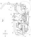
FIG. 1 is a left side view of a tractor. -
FIG. 2 is a left side view showing an arrangement of an inverter and the like. -
FIG. 3 is a diagram showing a flow of power transmission. -
FIG. 4 is a diagram showing a power transmission mechanism. -
FIG. 5 is a partially cutaway left side view showing a configuration of a power transmission shaft and the like. -
FIG. 6 is a block diagram showing a configuration of a control section. -
FIG. 7 is a hydraulic circuit diagram showing a configuration of a relief mechanism and the like. -
FIG. 8 is a flowchart of a reduction control flow. -
FIG. 9 is a block diagram showing a configuration of the control section in a first alternative embodiment. -
FIG. 10 is a flowchart of the reduction control flow in the first alternative embodiment. -
FIG. 11 is a schematic side view of a power transmission device of a tractor in another embodiment (8). -
FIG. 12 is a schematic side view showing a power transmission device of a tractor in another embodiment (9). - Embodiments of the present invention will be described below based on the drawings. In the following description, unless otherwise stated, the direction of an arrow F and the direction of an arrow B in the drawings will be respectively referred to as "the front side" and "the rear side", and the direction of an arrow L and the direction of an arrow R in the drawings will be respectively referred to as "the left side" and "the right side". Also, the direction of an arrow U and the direction of an arrow D in the drawings will be respectively referred to as "the upper side" and "the lower side".
- The following describes a tractor according to the present embodiment. As shown in
FIG. 1 , the tractor includes left and rightfront wheels 10, left and rightrear wheels 11, and acover member 12. - The tractor also includes a
body frame 2 and adriving section 3. Thebody frame 2 is supported by the left and rightfront wheels 10 and the left and rightrear wheels 11. - The
cover member 12 is disposed in a front portion of the body of the tractor. Thedriving section 3 is behind thecover member 12. In other words, thecover member 12 is in front of thedriving section 3. - The
driving section 3 includes aprotective frame 30, a driver'sseat 31, and asteering wheel 32. An operator can sit on the driver'sseat 31. Accordingly, the operator can get on thedriving section 3. The operator steers the left and rightfront wheels 10 by operating thesteering wheel 32. The operator can perform various driving operations in thedriving section 3. - The tractor includes a
battery 4 for traveling. Thecover member 12 is configured to be pivotable about an opening/closing axis Q extending in the left-right direction of the body. Accordingly, thecover member 12 is configured to be openable and closable. When thecover member 12 is closed, thebattery 4 for traveling is covered by thecover member 12. - As shown in
FIG. 2 , the tractor includes aninverter 14 and a motor M. Thebattery 4 for traveling supplies electric power to theinverter 14. Theinverter 14 converts DC power supplied from thebattery 4 for traveling to AC power, and supplies the AC power to the motor M. The motor M is driven by the AC power supplied from theinverter 14. - As shown in
FIGS. 2 and3 , the tractor includes a hydraulic continuouslyvariable transmission 15 and atransmission 16. As shown inFIG. 3 , the hydraulic continuouslyvariable transmission 15 includes ahydraulic pump 15a and ahydraulic motor 15b. - The
hydraulic pump 15a is driven by rotational power received from the motor M. As a result of thehydraulic pump 15a being driven, rotational power is output from thehydraulic motor 15b. The hydraulic continuouslyvariable transmission 15 is configured to change the speed of rotational power between thehydraulic pump 15a and thehydraulic motor 15b. Also, the hydraulic continuouslyvariable transmission 15 is configured to be capable of changing the transmission ratio in a stepless manner. - The rotational power output from the
hydraulic motor 15b is transmitted to thetransmission 16. The speed of the rotational power transmitted to thetransmission 16 is changed by a gear transmission mechanism included in thetransmission 16, and the resulting rotational power is distributed to the left and rightfront wheels 10 and the left and rightrear wheels 11. The left and rightfront wheels 10 and the left and rightrear wheels 11 are driven in this way. - Also, as shown in
FIGS. 2 and3 , the tractor includes amid PTO shaft 17 and arear PTO shaft 18. The rotational power output from the motor M is distributed to thehydraulic pump 15a, themid PTO shaft 17, and therear PTO shaft 18. Themid PTO shaft 17 and therear PTO shaft 18 thus rotate. - If a work device is connected to the
mid PTO shaft 17 or therear PTO shaft 18, the work device is driven by rotational power from themid PTO shaft 17 or therear PTO shaft 18. For example, as shown inFIG. 2 , in the present embodiment, amowing device 19 is connected to themid PTO shaft 17. Themowing device 19 is driven by rotational power from themid PTO shaft 17. - According to the above configuration, the tractor of the present embodiment includes the
battery 4 for traveling, the motor M driven by electric power supplied from thebattery 4 for traveling, and the left and rightfront wheels 10 and the left and rightrear wheels 11 that are driven by rotational power output from the motor M. - Also, this tractor includes the
mid PTO shaft 17 and therear PTO shaft 18 that can each be connected to a work device and can transmit rotational power from the motor M to the work device. - Also, in this tractor, the hydraulic continuously
variable transmission 15 changes the speed of the rotational power input to the hydraulic continuouslyvariable transmission 15, and outputs the resulting rotational power to the left and rightfront wheels 10 and the left and rightrear wheels 11. - Note that this tractor corresponds to an "electric work vehicle" according to the present invention. The
battery 4 for traveling corresponds to a "battery" according to the present invention. The left and rightfront wheels 10 and the left and rightrear wheels 11 both correspond to a "travel device" according to the present invention. Themid PTO shaft 17 and therear PTO shaft 18 both correspond to a "power take-off shaft" according to the present invention. Themowing device 19 corresponds to a "work device" according to the present invention. - As shown in
FIG. 4 , the tractor includes adistribution mechanism 20. Thedistribution mechanism 20 includes a power transmission shaft MB, afirst shaft 21, afirst gear mechanism 22, asecond gear mechanism 23, asecond shaft 24, athird gear mechanism 25, a first clutch 26, and asecond clutch 27. The first clutch 26 and the second clutch 27 can both be changed between an engaged state in which motive power is transmitted and a disengaged state in which motive power is not transmitted. - An output shaft MA of the motor M is connected to the
first shaft 21 via the power transmission shaft MB. The output shaft MA, the power transmission shaft MB, and thefirst shaft 21 rotate integrally. Thefirst shaft 21 is coupled to thehydraulic pump 15a. When the first clutch 26 is in the engaged state, rotational power is transmitted from thefirst shaft 21 to thefirst gear mechanism 22. Furthermore, when the second clutch 27 is in the engaged state, rotational power is transmitted from thefirst shaft 21 to thesecond shaft 24. - According to this configuration, rotational power output from the motor M is distributed from the
first shaft 21 to thehydraulic pump 15a, thefirst gear mechanism 22, and thesecond shaft 24. - The rotational power transmitted to the
first gear mechanism 22 is transmitted to themid PTO shaft 17 via thesecond gear mechanism 23. Themid PTO shaft 17 thus rotates. - The rotational power transmitted to the
second shaft 24 is transmitted to therear PTO shaft 18 via thethird gear mechanism 25. Therear PTO shaft 18 thus rotates. - As described above, the tractor of the present embodiment includes the
distribution mechanism 20 that distributes the rotational power output from the motor M to the hydraulic continuouslyvariable transmission 15, themid PTO shaft 17, and therear PTO shaft 18. - According to the above configuration, when the motor M is driven to rotate, the
mid PTO shaft 17 rotates if the first clutch 26 is in the engaged state, whereas themid PTO shaft 17 does not rotate if the first clutch 26 is in the disengaged state. Also, when the motor M is driven to rotate, therear PTO shaft 18 rotates if the second clutch 27 is in the engaged state, whereas therear PTO shaft 18 does not rotate if the second clutch 27 is in the disengaged state. - The speed of the rotational power transmitted to the
hydraulic pump 15a is changed via hydraulic pressure in the hydraulic continuouslyvariable transmission 15, and the resulting rotational power is output from thehydraulic motor 15b. The rotational power output from thehydraulic motor 15b is transmitted via athird shaft 41 to atransmission section 16a, which is a gear transmission mechanism included in thetransmission 16. The speed of the rotational power transmitted to thetransmission section 16a is changed by thetransmission section 16a, and the resulting rotational power is distributed to a power transmission shaft X and a rearwheel differential mechanism 43. The rotational power transmitted to the power transmission shaft X is transmitted to the left and rightfront wheels 10 via a transmission connection section Z and a power transmission shaft Y. The left and rightfront wheels 10 are thus driven. The left and rightrear wheels 11 are driven by rotational power transmitted to the rearwheel differential mechanism 43. - As shown in
FIGS. 2 and5 , the power transmission shaft X extends diagonally forward so as to pass between cases W coupled to the hydraulic continuouslyvariable transmission 15 and transmit motive power from thetransmission 16. A frontwheel input section 10A, to which motive power for the left and rightfront wheels 10 is input, is arranged at a position lower than the upper end of the power transmission shaft X in the power transmission direction. By employing a configuration in which the power transmission shaft X is connected to the frontwheel input section 10A via the transmission connection section Z and the power transmission shaft Y, it is possible to transmit motive power from the upper end of the power transmission shaft X in the power transmission direction to the frontwheel input section 10A, which is located at a different height from the upper end. The transmission connection section Z is arranged below the motor M and is surrounded by thebody frame 2. - Also, as shown in
FIGS. 2 and5 , by arranging the motor M and the hydraulic continuouslyvariable transmission 15 at positions spaced apart from each other and connecting them to each other with the power transmission shaft MB, resonant vibration is less likely to occur. Since theinverter 14 is susceptible to vibration, a structure is employed in which theinverter 14 is connected to thebody frame 2, and thebattery 4 for traveling is arranged above theinverter 14, thus suppressing vibration in the vicinity of theinverter 14. Also, theinverter 14 is spaced apart from the hydraulic continuouslyvariable transmission 15 to prevent problems caused by vibration. - As shown in
FIG. 5 , aradiator 80, a DC-DC (Direct Current - Direct Current)converter 81, and anauxiliary battery 82 are arranged in front of thebattery 4 for traveling. Theradiator 80 and a water pump (not shown) are included in a cooling water path in the tractor. When the water pump pumps cooling water, the cooling water circulates through the cooling water path. The cooling water is cooled by passing through theradiator 80. - Also, electric power is supplied from the
battery 4 for traveling to the DC-DC converter 81. The DC-DC converter 81 steps down the voltage of the power from thebattery 4 for traveling and supplies the resulting power to theauxiliary battery 82. Theauxiliary battery 82 supplies electric power to various auxiliary devices. - As shown in
FIG. 6 , the tractor includes anaccelerator operation tool 51, arotation operation tool 52, a speedchange operation tool 53, and acontrol section 54. Theaccelerator operation tool 51, therotation operation tool 52, and the speedchange operation tool 53 may be levers or buttons, for example, but are not particularly limited to this. Also, theaccelerator operation tool 51, therotation operation tool 52, and the speedchange operation tool 53 may be provided in thedriving section 3, for example. - The
control section 54 includes amotor control section 55, a workclutch control section 56, and a speedchange control section 57. - When the
accelerator operation tool 51 is manually operated, a signal corresponding to the operation is transmitted to themotor control section 55. Themotor control section 55 controls the output rotation speed of motor M by controlling theinverter 14 based on the signal. In other words, themotor control section 55 controls the output rotation speed of the motor M in accordance with a manual operation performed on theaccelerator operation tool 51. Also, theaccelerator operation tool 51 accepts an operation for changing the output rotation speed of the motor M. - In this way, the tractor of the present embodiment includes the
motor control section 55 that controls the motor M. - When the
rotation operation tool 52 is manually operated, a signal corresponding to the operation is transmitted to the workclutch control section 56. The workclutch control section 56 controls the engaged/disengaged states of the first clutch 26 and the second clutch 27 based on the signal. The workclutch control section 56 thereby controls the rotation states of themid PTO shaft 17 and therear PTO shaft 18. More specifically, the workclutch control section 56 switches the states of themid PTO shaft 17 and therear PTO shaft 18 between a rotating state and a non-rotating state. - In other words, the work
clutch control section 56 controls the rotation states of themid PTO shaft 17 and therear PTO shaft 18 in accordance with a manual operation performed on therotation operation tool 52. Also, therotation operation tool 52 accepts an operation for changing the rotation state of themid PTO shaft 17 and therear PTO shaft 18. - As described above, the tractor of the present embodiment includes the
rotation operation tool 52 that accepts an operation for changing the rotation state of themid PTO shaft 17 and therear PTO shaft 18. - When the speed
change operation tool 53 is manually operated, a signal corresponding to the operation is transmitted to the speedchange control section 57. The speedchange control section 57 controls the angle of apump swash plate 58 of thehydraulic pump 15a based on the signal. When the angle of thepump swash plate 58 changes, the transmission ratio in the hydraulic continuouslyvariable transmission 15 changes. In other words, the speedchange control section 57 controls the transmission state of the hydraulic continuouslyvariable transmission 15 in accordance with a manual operation performed on the speedchange operation tool 53. Also, the speedchange operation tool 53 accepts an operation for changing the transmission state of the hydraulic continuouslyvariable transmission 15. - The hydraulic continuously
variable transmission 15 is configured such that when thepump swash plate 58 is in a neutral state, rotational power is not output from thehydraulic motor 15b. Furthermore, the hydraulic continuouslyvariable transmission 15 is configured such that rotational power in the forward direction and the reverse direction can be output to the left and rightfront wheels 10 and the left and rightrear wheels 11 in accordance with the angle of thepump swash plate 58. In other words, the hydraulic continuouslyvariable transmission 15 is configured such that rotational power in the forward direction and the reverse direction can be output to the left and rightfront wheels 10 and the left and rightrear wheels 11 in accordance with a manual operation performed on the speedchange operation tool 53. - The tractor of the present embodiment can travel forward by driving the left and right
front wheels 10 and the left and rightrear wheels 11 with forward rotational power. Also, the tractor of the present embodiment can travel backward by driving the left and rightfront wheels 10 and the left and rightrear wheels 11 with reverse rotational power. - When the tractor of the present embodiment is to perform work while traveling, the operator operates the
accelerator operation tool 51 to set the output rotation speed of the motor M to a rotation speed that corresponds to a target rotation speed of themid PTO shaft 17 or therear PTO shaft 18. Themotor control section 55 is able to maintain the output rotation speed of the motor M at the rotation speed set by the manual operation performed on theaccelerator operation tool 51 while the tractor is performing work and traveling. - In other words, the
motor control section 55 can perform maintenance control for maintaining the output rotation speed of the motor M at a rotation speed that corresponds to a target rotation speed of themid PTO shaft 17 or therear PTO shaft 18. - Furthermore, even while the
motor control section 55 is performing maintenance control, the transmission state of the hydraulic continuouslyvariable transmission 15 can be changed by manually operating the speedchange operation tool 53. Accordingly, it is possible to change the vehicle speed while maintaining the rotation speed of themid PTO shaft 17 or therear PTO shaft 18. - In this way, the transmission state of the hydraulic continuously
variable transmission 15 can be changed in accordance with a manual operation performed on the speedchange operation tool 53 while maintenance control is being executed. - Note that elements such as the
control section 54 and themotor control section 55 included in thecontrol section 54 may be a physical device such as a microcomputer, or may be a functional unit in software. - As shown in
FIG. 7 , the hydraulic continuouslyvariable transmission 15 includes ahydraulic circuit 60. Thehydraulic pump 15a and thehydraulic motor 15b are included in thehydraulic circuit 60. Also, the hydraulic continuouslyvariable transmission 15 includes anoil pump 61 and arelief mechanism 62. - The
oil pump 61 is coupled to thefirst shaft 21. Theoil pump 61 is configured to be driven by rotational power from thefirst shaft 21. Theoil pump 61 supplies oil (hydraulic oil) to thehydraulic circuit 60. - Note that the present invention is not limited to this, and the
oil pump 61 may be provided outside the hydraulic continuouslyvariable transmission 15. Also, theoil pump 61 may be configured to be driven by rotational power from a member other than thefirst shaft 21. - The
relief mechanism 62 is connected to thehydraulic circuit 60. Therelief mechanism 62 is a mechanism that discharges oil (hydraulic oil) in thehydraulic circuit 60 to the outside of thehydraulic circuit 60 in the case where the hydraulic pressure in thehydraulic circuit 60 exceeds a predetermined threshold value. According to this configuration, when the hydraulic pressure in thehydraulic circuit 60 exceeds the predetermined threshold, oil is discharged from thehydraulic circuit 60 via therelief mechanism 62. In this way, the hydraulic continuouslyvariable transmission 15 has therelief mechanism 62. - The
motor control section 55 shown inFIG. 6 is configured to execute reduction control in the case where the hydraulic continuouslyvariable transmission 15 is in a transmission state in which rotational power is not output from the hydraulic continuouslyvariable transmission 15 and furthermore therotation operation tool 52 has been operated such that themid PTO shaft 17 and therear PTO shaft 18 do not rotate. The reduction control is control for reducing the output torque of the motor M. Also, in the present embodiment, the driving of the motor M is stopped in the reduction control. - In other words, the
motor control section 55 executes reduction control for reducing the output torque of the motor M in the case where the hydraulic continuouslyvariable transmission 15 is in a transmission state in which rotational power is not output from the hydraulic continuouslyvariable transmission 15 and furthermore therotation operation tool 52 has been operated such that themid PTO shaft 17 and therear PTO shaft 18 do not rotate. - The reduction control will be described below. The
motor control section 55 executes the reduction control in accordance with the reduction control flow shown inFIG. 8 . This reduction control flow is repeatedly executed at regular intervals while the motor M is driven to rotate. - When this reduction control flow is started, first, the processing of step S01 is executed. In step S01, as shown in
FIG. 6 , information indicating the operation state of therotation operation tool 52 is transmitted from therotation operation tool 52 to themotor control section 55. Based on the information, themotor control section 55 determines whether or not therotation operation tool 52 has been operated such that themid PTO shaft 17 and therear PTO shaft 18 do not rotate. - If the
rotation operation tool 52 has not been operated such that themid PTO shaft 17 and therear PTO shaft 18 do not rotate ("No" in step S01 ofFIG. 8 ), the reduction control flow ends. - If the
rotation operation tool 52 has been operated such that themid PTO shaft 17 and therear PTO shaft 18 do not rotate ("Yes" in step S01 ofFIG. 8 ), the processing moves to step S02. - In step S02, as shown in
FIG. 6 , information indicating the operation state of the speedchange operation tool 53 is transmitted from the speedchange operation tool 53 to themotor control section 55. Based on the information, themotor control section 55 determines whether or not the hydraulic continuouslyvariable transmission 15 is in a transmission state in which rotational power is not output from the hydraulic continuouslyvariable transmission 15. More specifically, themotor control section 55 determines whether or not thepump swash plate 58 is in the neutral state. - If the
pump swash plate 58 is not in the neutral state ("No" in step S02 ofFIG. 8 ), the reduction control flow ends. - If the
pump swash plate 58 is in the neutral state ("Yes" in step S02 ofFIG. 8 ), the processing moves to step S03. - In step S03, the above-described reduction control is executed by the
motor control section 55. The reduction control flow then ends. - Although the present invention is not particularly limited to this, a configuration is possible in which after the reduction control is executed, the output torque of the motor M is returned to the original value when the hydraulic continuously
variable transmission 15 enters a transmission state in which rotational power is output from the hydraulic continuouslyvariable transmission 15, or the output torque of the motor M is returned to the original value when therotation operation tool 52 is operated such that themid PTO shaft 17 or therear PTO shaft 18 rotates, for example. Note that returning the output torque to the original value means returning the output torque to the value before execution of the reduction control. - According to the configuration described above, if the speed
change operation tool 53 is manually operated while maintenance control is being executed, the speed of the rotational power output from the hydraulic continuouslyvariable transmission 15 to the left and rightfront wheels 10 and the left and rightrear wheels 11 changes while the rotation speed of themid PTO shaft 17 or therear PTO shaft 18 is maintained at the target rotation speed. As a result, the vehicle speed changes. - In other words, according to the configuration described above, it is possible to realize a tractor in which the vehicle speed can be changed while maintaining the rotation speed of the
mid PTO shaft 17 or therear PTO shaft 18 at the target rotation speed. - In the embodiment described above, the hydraulic continuously
variable transmission 15 is provided. - However, the present invention is not limited to this. Below, a first alternative embodiment of the present invention will be described, focusing on differences from the above embodiment. Configurations of portions other than the portions described below are similar to those of the above embodiment. Also, configurations similar to those of the above embodiment are denoted by the same reference numerals.
- As shown in
FIG. 9 , in the first alternative embodiment, atravel clutch 72 is provided in place of the hydraulic continuouslyvariable transmission 15. Also, in the first alternative embodiment, a travelclutch operation tool 70 and a travelclutch control section 71 are provided in place of the speedchange operation tool 53 and the speedchange control section 57. The travelclutch operation tool 70 may be a lever or a button, for example, but is not particularly limited to this. Furthermore, the travelclutch operation tool 70 may be provided in thedriving section 3, for example. - The
travel clutch 72 can be changed between an engaged state in which power is transmitted and a disengaged state in which power is not transmitted. The power transmission mechanism of the first alternative embodiment is configured such that when thetravel clutch 72 is in the engaged state, rotational power is transmitted from thefirst shaft 21 to thethird shaft 41 via thetravel clutch 72. When thetravel clutch 72 is in the disengaged state, rotational power from the motor M is not transmitted to the left and rightfront wheels 10 and the left and rightrear wheels 11. - When the travel
clutch operation tool 70 is manually operated, a signal corresponding to the operation is transmitted to the travelclutch control section 71. The travelclutch control section 71 controls the engaged/disengaged state of thetravel clutch 72 based on the signal. In other words, the travelclutch control section 71 controls the engaged/disengaged state of thetravel clutch 72 in accordance with a manual operation performed on the travelclutch operation tool 70. - In the first alternative embodiment, the
motor control section 55 executes the above-described reduction control in the case where thetravel clutch 72 is in the disengaged state and furthermore therotation operation tool 52 has been operated such that themid PTO shaft 17 and therear PTO shaft 18 do not rotate. - More specifically, the
motor control section 55 of the first alternative embodiment executes the reduction control in accordance with the reduction control flow shown inFIG. 10 . This reduction control flow is repeatedly executed at regular intervals while the motor M is driven to rotate. - When the reduction control flow is started, first, the processing of step S11 is executed. In step S11, similarly to step S01 in
FIG. 8 , it is determined whether or not therotation operation tool 52 has been operated such that themid PTO shaft 17 and therear PTO shaft 18 do not rotate. - If the
rotation operation tool 52 has not been operated such that themid PTO shaft 17 and therear PTO shaft 18 do not rotate ("No" in step S11 ofFIG. 10 ), the reduction control flow ends. - If the
rotation operation tool 52 has been operated such that themid PTO shaft 17 and therear PTO shaft 18 do not rotate ("Yes" in step S11 ofFIG. 10 ), the processing moves to step S12. - In step S12, as shown in
FIG. 9 , information indicating the operation state of the travelclutch operation tool 70 is transmitted from the travelclutch operation tool 70 to themotor control section 55. Based on the information, themotor control section 55 determines whether or not thetravel clutch 72 is in the disengaged state. - If the
travel clutch 72 is not in the disengaged state ("No" in step S12 ofFIG. 10 ), the reduction control flow ends. - If the
travel clutch 72 is in the disengaged state ("Yes" in step S12 ofFIG. 10 ), the processing moves to step S13. - In step S13, the
motor control section 55 executes the above-described reduction control. The reduction control flow then ends. -
- (1) The rotation speed that corresponds to the target rotation speed of the
mid PTO shaft 17 or therear PTO shaft 18 may be determined in advance and not be dependent on manual operation of theaccelerator operation tool 51. In this case, theaccelerator operation tool 51 may be omitted. - (2) The
rotation operation tool 52 may be linked to the first clutch 26 and the second clutch 27 by a mechanical link. In this case, the workclutch control section 56 may be omitted. - (3) The speed
change operation tool 53 may be linked to thepump swash plate 58 by a mechanical link. In this case, the speedchange control section 57 may be omitted. - (4) The hydraulic continuously
variable transmission 15 may be configured such that reverse rotational power cannot be output. - (5) In the reduction control, the driving of the motor M does not need to be stopped.
- (6) The
motor control section 55 may be configured to not execute reduction control. - (7) Either the
mid PTO shaft 17 or therear PTO shaft 18 may be omitted. - (8) The tractor may be configured as shown in
FIG. 11 . In the tractor shown inFIG. 11 , a first front PTO shaft 91 (corresponding to a "power take-off shaft" and a "front power take-off shaft" according to the present invention) is provided in a front section of the body of the tractor. The firstfront PTO shaft 91 extracts motive power from the motor M. - Specifically, the first
front PTO shaft 91 is rotatably supported by afirst support section 92 provided in a front section of thebody frame 2. A rear section of the firstfront PTO shaft 91 is coupled to an output section M2 of the motor M via arotation shaft 93. Therotation shaft 93 is rotatably supported by asecond support section 94 of thebody frame 2, between thefirst support section 92 and the output section M2. Motive power generated by the motor M and output from the output section M2 is transmitted to the firstfront PTO shaft 91 via therotation shaft 93. - In this configuration, the first
front PTO shaft 91 can be connected to the work device and can transmit rotational power from the motor M to the work device. Also, according to a configuration similar to that of the above embodiment, themotor control section 55 can execute maintenance control for maintaining the output rotation speed of the motor M at a rotation speed corresponding to the target rotation speed of the firstfront PTO shaft 91. Furthermore, according to a configuration similar to that of the above embodiment, therotation operation tool 52 accepts an operation for changing the rotation state of the firstfront PTO shaft 91. Also, according to a configuration similar to that of the above embodiment, themotor control section 55 executes the reduction control for reducing the output torque of the motor M in the case where the hydraulic continuouslyvariable transmission 15 is in a transmission state in which rotational power is not output from the hydraulic continuouslyvariable transmission 15 and furthermore therotation operation tool 52 has been operated such that themid PTO shaft 17, therear PTO shaft 18, and the firstfront PTO shaft 91 do not rotate. - Furthermore, in this configuration, the output section M2 is included in the previously described
distribution mechanism 20. In other words, in this configuration, thedistribution mechanism 20 distributes the rotational power output from the motor M to the hydraulic continuouslyvariable transmission 15, themid PTO shaft 17, therear PTO shaft 18, and the firstfront PTO shaft 91. - (9) The tractor may be configured as shown in
FIG. 12 . In the tractor shown inFIG. 12 , a second front PTO shaft 95 (corresponding to a "power take-off shaft" and a "front power take-off shaft" according to the present invention) is provided in a front section of the tractor body. The secondfront PTO shaft 95 extracts motive power from the motor M. - Specifically, the second
front PTO shaft 95 is rotatably supported by afirst support section 92 provided in a front section of thebody frame 2. A rear section of the secondfront PTO shaft 95 is coupled to a power take-offsection 96a, which is provided in aninput case 96 of themowing device 19, via arotation shaft 97. Therotation shaft 97 is rotatably supported by asecond support section 94 of thebody frame 2, between thefirst support section 92 and the power take-offsection 96a. Auniversal joint 98, which serves as a bending section that allows raising and lowering of themowing device 19, is provided on therotation shaft 97 at a portion between thesecond support section 94 and the power take-offsection 96a. Motive power output by the motor M is transmitted to the secondfront PTO shaft 95 via themid PTO shaft 17, theinput case 96, and therotation shaft 97. - In this configuration, the second
front PTO shaft 95 can be connected to the work device and can transmit rotational power from the motor M to the work device. Also, according to a configuration similar to that of the above embodiment, themotor control section 55 can execute maintenance control for maintaining the output rotation speed of the motor M at a rotation speed corresponding to the target rotation speed of the secondfront PTO shaft 95. Furthermore, according to a configuration similar to that of the above embodiment, therotation operation tool 52 accepts an operation for changing the rotation state of the secondfront PTO shaft 95. Also, according to a configuration similar to that of the above embodiment, themotor control section 55 executes the reduction control for reducing the output torque of the motor M in the case where the hydraulic continuouslyvariable transmission 15 is in a transmission state in which rotational power is not output from the hydraulic continuouslyvariable transmission 15 and furthermore therotation operation tool 52 has been operated such that themid PTO shaft 17, therear PTO shaft 18, and the secondfront PTO shaft 95 do not rotate. - Also, in this configuration, the previously described the
distribution mechanism 20 distributes the rotational power output from the motor M to the hydraulic continuouslyvariable transmission 15, to themid PTO shaft 17 and the secondfront PTO shaft 95, and to therear PTO shaft 18. The secondfront PTO shaft 95 is located downstream of themid PTO shaft 17 in the flow of motive power transmission. - Note that the configurations disclosed in the above-described embodiments (including the alternative embodiments, which similarly applies hereinafter) can be applied in combination with configurations disclosed in other embodiments as long as no contradiction arises. Also, the embodiments disclosed in this specification are illustrative, and the embodiments of the present invention are not limited to this, and can be modified as appropriate without departing from the object of the present invention.
- The present invention is applicable to not only a tractor but also various electric work vehicles such as a combine, a rice transplanter, and a construction machine.
-
- 4
- Battery for travel (battery)
- 10
- Front wheel (travel device)
- 11
- Rear wheel (travel device)
- 15
- Hydraulic continuously variable transmission
- 17
- Mid PTO shaft (power take-off shaft)
- 18
- Rear PTO shaft (power take-off shaft)
- 19
- Mowing device (work device)
- 20
- Distribution mechanism
- 52
- Rotation operation tool
- 53
- Speed change operation tool
- 55
- Motor control section
- 62
- Relief mechanism
- 91
- First front PTO shaft (power take-off shaft, front power take-off shaft)
- 95
- Second front PTO shaft (power take-off shaft, front power take-off shaft)
- M
- Motor
Claims (6)
- An electric work vehicle comprising:a battery;a motor configured to be driven with electric power supplied from the battery;a travel device configured to be driven with rotational power output from the motor;a motor control section configured to control the motor;a power take-off shaft connectable to a work device and configured to transmit the rotational power from the motor to the work device; anda distribution mechanism configured to distribute the rotational power output from the motor to a hydraulic continuously variable transmission and the power take-off shaft,the hydraulic continuously variable transmission being configured to change a speed of the rotational power input to the hydraulic continuously variable transmission, and output resulting rotational power to the travel device,the motor control section being further configured to execute maintenance control to maintain an output rotation speed of the motor at a rotation speed corresponding to a target rotation speed of the power take-off shaft, andthe hydraulic continuously variable transmission having a transmission state changeable according to manual operation of a speed change operation tool while the maintenance control is executed.
- The electric work vehicle according to claim 1,
wherein the hydraulic continuously variable transmission includes a relief mechanism. - The electric work vehicle according to claim 1 or 2,wherein the hydraulic continuously variable transmission outputs forward rotational power or reverse rotational power to the travel device according to manual operation of the speed change operation tool,the electric work vehicle travels forward while the travel device is driven by the forward rotational power, andthe electric work vehicle travels backward while the travel device is driven by the reverse rotational power.
- The electric work vehicle according to any one of claims 1 to 3, further comprising:a rotation operation tool configured to accept an operation to change a rotation state of the power take-off shaft,wherein in a case where (i) the hydraulic continuously variable transmission is in a transmission state in which rotational power is not output from the hydraulic continuously variable transmission, and (ii) the rotation operation tool has been operated in such a manner that the power take-off shaft does not rotate, the motor control section executes reduction control to reduce an output torque of the motor.
- The electric work vehicle according to claim 4,
wherein driving of the motor is stopped in the reduction control. - The electric work vehicle according to any one of claims 1 to 5,
wherein the power take-off shaft is a front power take-off shaft provided in a front section of a body of the electric work vehicle.
Applications Claiming Priority (2)
| Application Number | Priority Date | Filing Date | Title |
|---|---|---|---|
| JP2021211641A JP7770183B2 (en) | 2021-12-24 | 2021-12-24 | electric work vehicle |
| PCT/JP2022/044544 WO2023120115A1 (en) | 2021-12-24 | 2022-12-02 | Electric work vehicle |
Publications (2)
| Publication Number | Publication Date |
|---|---|
| EP4454447A1 true EP4454447A1 (en) | 2024-10-30 |
| EP4454447A4 EP4454447A4 (en) | 2025-12-17 |
Family
ID=86902136
Family Applications (1)
| Application Number | Title | Priority Date | Filing Date |
|---|---|---|---|
| EP22910832.9A Pending EP4454447A4 (en) | 2021-12-24 | 2022-12-02 | ELECTRIC WORK VEHICLE |
Country Status (4)
| Country | Link |
|---|---|
| US (1) | US20240317049A1 (en) |
| EP (1) | EP4454447A4 (en) |
| JP (1) | JP7770183B2 (en) |
| WO (1) | WO2023120115A1 (en) |
Families Citing this family (2)
| Publication number | Priority date | Publication date | Assignee | Title |
|---|---|---|---|---|
| EP4497623A3 (en) * | 2023-07-10 | 2025-04-23 | Kubota Corporation | Electric work vehicle and work vehicle |
| EP4674664A1 (en) * | 2024-07-01 | 2026-01-07 | Deere & Company | Method for coordinating an electric drive system for an agricultural tractor |
Family Cites Families (11)
| Publication number | Priority date | Publication date | Assignee | Title |
|---|---|---|---|---|
| JP3317517B2 (en) * | 1992-06-04 | 2002-08-26 | マツダ株式会社 | Power transmission device for four-wheel drive vehicles |
| JP2000062482A (en) | 1998-08-20 | 2000-02-29 | Kobe Steel Ltd | Wheel crane |
| US6758301B2 (en) * | 2000-09-14 | 2004-07-06 | Kenji Shiba | Tractor |
| JP2002356116A (en) | 2001-05-30 | 2002-12-10 | Iseki & Co Ltd | Electric powered vehicle |
| JP5826042B2 (en) | 2012-01-12 | 2015-12-02 | 株式会社クボタ | Electric work vehicle |
| JP2014143965A (en) * | 2013-01-30 | 2014-08-14 | Iseki & Co Ltd | Tractor |
| JP2017171428A (en) | 2016-03-22 | 2017-09-28 | 株式会社タダノ | Crane truck |
| JP7054464B2 (en) | 2017-02-23 | 2022-04-14 | いすゞ自動車株式会社 | Propeller shaft guard |
| JP2020162282A (en) | 2019-03-26 | 2020-10-01 | ヤンマーパワーテクノロジー株式会社 | Work vehicle |
| JP7197433B2 (en) | 2019-06-11 | 2022-12-27 | 株式会社小松製作所 | WORK VEHICLE CONTROL DEVICE, WORK VEHICLE, AND WORK VEHICLE CONTROL METHOD |
| JP7304750B2 (en) | 2019-06-24 | 2023-07-07 | 株式会社クボタ | electric work vehicle |
-
2021
- 2021-12-24 JP JP2021211641A patent/JP7770183B2/en active Active
-
2022
- 2022-12-02 WO PCT/JP2022/044544 patent/WO2023120115A1/en not_active Ceased
- 2022-12-02 EP EP22910832.9A patent/EP4454447A4/en active Pending
-
2024
- 2024-06-05 US US18/734,389 patent/US20240317049A1/en active Pending
Also Published As
| Publication number | Publication date |
|---|---|
| JP7770183B2 (en) | 2025-11-14 |
| JP2023095633A (en) | 2023-07-06 |
| US20240317049A1 (en) | 2024-09-26 |
| EP4454447A4 (en) | 2025-12-17 |
| WO2023120115A1 (en) | 2023-06-29 |
Similar Documents
| Publication | Publication Date | Title |
|---|---|---|
| US20240317049A1 (en) | Electric work vehicle | |
| EP3777507B1 (en) | Work vehicle and grass mowing machine | |
| US12311769B2 (en) | Work vehicle | |
| EP3401153A1 (en) | Electric work vehicle | |
| JP2014143965A (en) | Tractor | |
| US20240326618A1 (en) | Electric work vehicle | |
| US20240217349A1 (en) | Electric Work Vehicle | |
| US20240326611A1 (en) | Electric work vehicle | |
| US12409740B2 (en) | Electric work vehicle | |
| EP4491424A1 (en) | Work vehicle | |
| US20250033488A1 (en) | Electric work vehicle | |
| JP6735698B2 (en) | Work vehicle | |
| EP3883801B1 (en) | Specialty tractor | |
| JP2024025397A (en) | Charging system and charging method | |
| JP7507742B2 (en) | Electric work vehicle | |
| EP4454914A1 (en) | Electric work vehicle | |
| EP4454924A1 (en) | Electric motor power train and utility vehicle | |
| EP4458602A1 (en) | Electric work vehicle | |
| EP4470827A1 (en) | Electric work vehicle | |
| US12420634B2 (en) | Electric work vehicle | |
| EP4497617A1 (en) | Work vehicle | |
| EP3941185A1 (en) | Electrically powered, universal accessory drive | |
| JPH10151953A (en) | Tractor turning control device |
Legal Events
| Date | Code | Title | Description |
|---|---|---|---|
| STAA | Information on the status of an ep patent application or granted ep patent |
Free format text: STATUS: THE INTERNATIONAL PUBLICATION HAS BEEN MADE |
|
| PUAI | Public reference made under article 153(3) epc to a published international application that has entered the european phase |
Free format text: ORIGINAL CODE: 0009012 |
|
| STAA | Information on the status of an ep patent application or granted ep patent |
Free format text: STATUS: REQUEST FOR EXAMINATION WAS MADE |
|
| 17P | Request for examination filed |
Effective date: 20240606 |
|
| AK | Designated contracting states |
Kind code of ref document: A1 Designated state(s): AL AT BE BG CH CY CZ DE DK EE ES FI FR GB GR HR HU IE IS IT LI LT LU LV MC ME MK MT NL NO PL PT RO RS SE SI SK SM TR |
|
| DAV | Request for validation of the european patent (deleted) | ||
| DAX | Request for extension of the european patent (deleted) | ||
| REG | Reference to a national code |
Ref country code: DE Ref legal event code: R079 Free format text: PREVIOUS MAIN CLASS: A01B0071020000 Ipc: F16H0047020000 |
|
| A4 | Supplementary search report drawn up and despatched |
Effective date: 20251118 |
|
| RIC1 | Information provided on ipc code assigned before grant |
Ipc: F16H 47/02 20060101AFI20251112BHEP Ipc: A01B 71/02 20060101ALI20251112BHEP Ipc: B60L 15/00 20060101ALI20251112BHEP Ipc: B60L 15/20 20060101ALI20251112BHEP Ipc: A01D 34/64 20060101ALI20251112BHEP Ipc: B60K 17/10 20060101ALI20251112BHEP Ipc: B60K 17/28 20060101ALI20251112BHEP Ipc: B60L 50/60 20190101ALI20251112BHEP Ipc: H02M 7/48 20070101ALI20251112BHEP |