EP4453467B1 - Vorrichtung und verfahren zum füllen eines raumes mit einem unter druck stehenden fluid und dann zum entleeren dieses raumes mit rückgewinnung des fluids - Google Patents
Vorrichtung und verfahren zum füllen eines raumes mit einem unter druck stehenden fluid und dann zum entleeren dieses raumes mit rückgewinnung des fluids Download PDFInfo
- Publication number
- EP4453467B1 EP4453467B1 EP22843347.0A EP22843347A EP4453467B1 EP 4453467 B1 EP4453467 B1 EP 4453467B1 EP 22843347 A EP22843347 A EP 22843347A EP 4453467 B1 EP4453467 B1 EP 4453467B1
- Authority
- EP
- European Patent Office
- Prior art keywords
- tank
- tanks
- pressure
- enclosure
- emptying
- Prior art date
- Legal status (The legal status is an assumption and is not a legal conclusion. Google has not performed a legal analysis and makes no representation as to the accuracy of the status listed.)
- Active
Links
Images
Classifications
-
- F—MECHANICAL ENGINEERING; LIGHTING; HEATING; WEAPONS; BLASTING
- F17—STORING OR DISTRIBUTING GASES OR LIQUIDS
- F17C—VESSELS FOR CONTAINING OR STORING COMPRESSED, LIQUEFIED OR SOLIDIFIED GASES; FIXED-CAPACITY GAS-HOLDERS; FILLING VESSELS WITH, OR DISCHARGING FROM VESSELS, COMPRESSED, LIQUEFIED, OR SOLIDIFIED GASES
- F17C13/00—Details of vessels or of the filling or discharging of vessels
- F17C13/02—Special adaptations of indicating, measuring, or monitoring equipment
- F17C13/025—Special adaptations of indicating, measuring, or monitoring equipment having the pressure as the parameter
-
- F—MECHANICAL ENGINEERING; LIGHTING; HEATING; WEAPONS; BLASTING
- F17—STORING OR DISTRIBUTING GASES OR LIQUIDS
- F17C—VESSELS FOR CONTAINING OR STORING COMPRESSED, LIQUEFIED OR SOLIDIFIED GASES; FIXED-CAPACITY GAS-HOLDERS; FILLING VESSELS WITH, OR DISCHARGING FROM VESSELS, COMPRESSED, LIQUEFIED, OR SOLIDIFIED GASES
- F17C5/00—Methods or apparatus for filling containers with liquefied, solidified, or compressed gases under pressures
- F17C5/06—Methods or apparatus for filling containers with liquefied, solidified, or compressed gases under pressures for filling with compressed gases
-
- F—MECHANICAL ENGINEERING; LIGHTING; HEATING; WEAPONS; BLASTING
- F17—STORING OR DISTRIBUTING GASES OR LIQUIDS
- F17C—VESSELS FOR CONTAINING OR STORING COMPRESSED, LIQUEFIED OR SOLIDIFIED GASES; FIXED-CAPACITY GAS-HOLDERS; FILLING VESSELS WITH, OR DISCHARGING FROM VESSELS, COMPRESSED, LIQUEFIED, OR SOLIDIFIED GASES
- F17C2201/00—Vessel construction, in particular geometry, arrangement or size
- F17C2201/05—Size
- F17C2201/054—Size medium (>1 m3)
-
- F—MECHANICAL ENGINEERING; LIGHTING; HEATING; WEAPONS; BLASTING
- F17—STORING OR DISTRIBUTING GASES OR LIQUIDS
- F17C—VESSELS FOR CONTAINING OR STORING COMPRESSED, LIQUEFIED OR SOLIDIFIED GASES; FIXED-CAPACITY GAS-HOLDERS; FILLING VESSELS WITH, OR DISCHARGING FROM VESSELS, COMPRESSED, LIQUEFIED, OR SOLIDIFIED GASES
- F17C2205/00—Vessel construction, in particular mounting arrangements, attachments or identifications means
- F17C2205/01—Mounting arrangements
- F17C2205/0123—Mounting arrangements characterised by number of vessels
- F17C2205/013—Two or more vessels
- F17C2205/0134—Two or more vessels characterised by the presence of fluid connection between vessels
- F17C2205/0142—Two or more vessels characterised by the presence of fluid connection between vessels bundled in parallel
-
- F—MECHANICAL ENGINEERING; LIGHTING; HEATING; WEAPONS; BLASTING
- F17—STORING OR DISTRIBUTING GASES OR LIQUIDS
- F17C—VESSELS FOR CONTAINING OR STORING COMPRESSED, LIQUEFIED OR SOLIDIFIED GASES; FIXED-CAPACITY GAS-HOLDERS; FILLING VESSELS WITH, OR DISCHARGING FROM VESSELS, COMPRESSED, LIQUEFIED, OR SOLIDIFIED GASES
- F17C2205/00—Vessel construction, in particular mounting arrangements, attachments or identifications means
- F17C2205/01—Mounting arrangements
- F17C2205/0123—Mounting arrangements characterised by number of vessels
- F17C2205/013—Two or more vessels
- F17C2205/0134—Two or more vessels characterised by the presence of fluid connection between vessels
- F17C2205/0146—Two or more vessels characterised by the presence of fluid connection between vessels with details of the manifold
-
- F—MECHANICAL ENGINEERING; LIGHTING; HEATING; WEAPONS; BLASTING
- F17—STORING OR DISTRIBUTING GASES OR LIQUIDS
- F17C—VESSELS FOR CONTAINING OR STORING COMPRESSED, LIQUEFIED OR SOLIDIFIED GASES; FIXED-CAPACITY GAS-HOLDERS; FILLING VESSELS WITH, OR DISCHARGING FROM VESSELS, COMPRESSED, LIQUEFIED, OR SOLIDIFIED GASES
- F17C2221/00—Handled fluid, in particular type of fluid
- F17C2221/01—Pure fluids
- F17C2221/012—Hydrogen
-
- F—MECHANICAL ENGINEERING; LIGHTING; HEATING; WEAPONS; BLASTING
- F17—STORING OR DISTRIBUTING GASES OR LIQUIDS
- F17C—VESSELS FOR CONTAINING OR STORING COMPRESSED, LIQUEFIED OR SOLIDIFIED GASES; FIXED-CAPACITY GAS-HOLDERS; FILLING VESSELS WITH, OR DISCHARGING FROM VESSELS, COMPRESSED, LIQUEFIED, OR SOLIDIFIED GASES
- F17C2221/00—Handled fluid, in particular type of fluid
- F17C2221/01—Pure fluids
- F17C2221/014—Nitrogen
-
- F—MECHANICAL ENGINEERING; LIGHTING; HEATING; WEAPONS; BLASTING
- F17—STORING OR DISTRIBUTING GASES OR LIQUIDS
- F17C—VESSELS FOR CONTAINING OR STORING COMPRESSED, LIQUEFIED OR SOLIDIFIED GASES; FIXED-CAPACITY GAS-HOLDERS; FILLING VESSELS WITH, OR DISCHARGING FROM VESSELS, COMPRESSED, LIQUEFIED, OR SOLIDIFIED GASES
- F17C2221/00—Handled fluid, in particular type of fluid
- F17C2221/01—Pure fluids
- F17C2221/016—Noble gases (Ar, Kr, Xe)
- F17C2221/017—Helium
-
- F—MECHANICAL ENGINEERING; LIGHTING; HEATING; WEAPONS; BLASTING
- F17—STORING OR DISTRIBUTING GASES OR LIQUIDS
- F17C—VESSELS FOR CONTAINING OR STORING COMPRESSED, LIQUEFIED OR SOLIDIFIED GASES; FIXED-CAPACITY GAS-HOLDERS; FILLING VESSELS WITH, OR DISCHARGING FROM VESSELS, COMPRESSED, LIQUEFIED, OR SOLIDIFIED GASES
- F17C2221/00—Handled fluid, in particular type of fluid
- F17C2221/03—Mixtures
- F17C2221/037—Containing pollutant, e.g. H2S, Cl
-
- F—MECHANICAL ENGINEERING; LIGHTING; HEATING; WEAPONS; BLASTING
- F17—STORING OR DISTRIBUTING GASES OR LIQUIDS
- F17C—VESSELS FOR CONTAINING OR STORING COMPRESSED, LIQUEFIED OR SOLIDIFIED GASES; FIXED-CAPACITY GAS-HOLDERS; FILLING VESSELS WITH, OR DISCHARGING FROM VESSELS, COMPRESSED, LIQUEFIED, OR SOLIDIFIED GASES
- F17C2223/00—Handled fluid before transfer, i.e. state of fluid when stored in the vessel or before transfer from the vessel
- F17C2223/01—Handled fluid before transfer, i.e. state of fluid when stored in the vessel or before transfer from the vessel characterised by the phase
- F17C2223/0107—Single phase
- F17C2223/0123—Single phase gaseous, e.g. CNG, GNC
-
- F—MECHANICAL ENGINEERING; LIGHTING; HEATING; WEAPONS; BLASTING
- F17—STORING OR DISTRIBUTING GASES OR LIQUIDS
- F17C—VESSELS FOR CONTAINING OR STORING COMPRESSED, LIQUEFIED OR SOLIDIFIED GASES; FIXED-CAPACITY GAS-HOLDERS; FILLING VESSELS WITH, OR DISCHARGING FROM VESSELS, COMPRESSED, LIQUEFIED, OR SOLIDIFIED GASES
- F17C2223/00—Handled fluid before transfer, i.e. state of fluid when stored in the vessel or before transfer from the vessel
- F17C2223/03—Handled fluid before transfer, i.e. state of fluid when stored in the vessel or before transfer from the vessel characterised by the pressure level
- F17C2223/035—High pressure (>10 bar)
-
- F—MECHANICAL ENGINEERING; LIGHTING; HEATING; WEAPONS; BLASTING
- F17—STORING OR DISTRIBUTING GASES OR LIQUIDS
- F17C—VESSELS FOR CONTAINING OR STORING COMPRESSED, LIQUEFIED OR SOLIDIFIED GASES; FIXED-CAPACITY GAS-HOLDERS; FILLING VESSELS WITH, OR DISCHARGING FROM VESSELS, COMPRESSED, LIQUEFIED, OR SOLIDIFIED GASES
- F17C2223/00—Handled fluid before transfer, i.e. state of fluid when stored in the vessel or before transfer from the vessel
- F17C2223/03—Handled fluid before transfer, i.e. state of fluid when stored in the vessel or before transfer from the vessel characterised by the pressure level
- F17C2223/036—Very high pressure (>80 bar)
-
- F—MECHANICAL ENGINEERING; LIGHTING; HEATING; WEAPONS; BLASTING
- F17—STORING OR DISTRIBUTING GASES OR LIQUIDS
- F17C—VESSELS FOR CONTAINING OR STORING COMPRESSED, LIQUEFIED OR SOLIDIFIED GASES; FIXED-CAPACITY GAS-HOLDERS; FILLING VESSELS WITH, OR DISCHARGING FROM VESSELS, COMPRESSED, LIQUEFIED, OR SOLIDIFIED GASES
- F17C2225/00—Handled fluid after transfer, i.e. state of fluid after transfer from the vessel
- F17C2225/01—Handled fluid after transfer, i.e. state of fluid after transfer from the vessel characterised by the phase
- F17C2225/0107—Single phase
- F17C2225/0123—Single phase gaseous, e.g. CNG, GNC
-
- F—MECHANICAL ENGINEERING; LIGHTING; HEATING; WEAPONS; BLASTING
- F17—STORING OR DISTRIBUTING GASES OR LIQUIDS
- F17C—VESSELS FOR CONTAINING OR STORING COMPRESSED, LIQUEFIED OR SOLIDIFIED GASES; FIXED-CAPACITY GAS-HOLDERS; FILLING VESSELS WITH, OR DISCHARGING FROM VESSELS, COMPRESSED, LIQUEFIED, OR SOLIDIFIED GASES
- F17C2225/00—Handled fluid after transfer, i.e. state of fluid after transfer from the vessel
- F17C2225/03—Handled fluid after transfer, i.e. state of fluid after transfer from the vessel characterised by the pressure level
- F17C2225/035—High pressure, i.e. between 10 and 80 bars
-
- F—MECHANICAL ENGINEERING; LIGHTING; HEATING; WEAPONS; BLASTING
- F17—STORING OR DISTRIBUTING GASES OR LIQUIDS
- F17C—VESSELS FOR CONTAINING OR STORING COMPRESSED, LIQUEFIED OR SOLIDIFIED GASES; FIXED-CAPACITY GAS-HOLDERS; FILLING VESSELS WITH, OR DISCHARGING FROM VESSELS, COMPRESSED, LIQUEFIED, OR SOLIDIFIED GASES
- F17C2225/00—Handled fluid after transfer, i.e. state of fluid after transfer from the vessel
- F17C2225/03—Handled fluid after transfer, i.e. state of fluid after transfer from the vessel characterised by the pressure level
- F17C2225/036—Very high pressure, i.e. above 80 bars
-
- F—MECHANICAL ENGINEERING; LIGHTING; HEATING; WEAPONS; BLASTING
- F17—STORING OR DISTRIBUTING GASES OR LIQUIDS
- F17C—VESSELS FOR CONTAINING OR STORING COMPRESSED, LIQUEFIED OR SOLIDIFIED GASES; FIXED-CAPACITY GAS-HOLDERS; FILLING VESSELS WITH, OR DISCHARGING FROM VESSELS, COMPRESSED, LIQUEFIED, OR SOLIDIFIED GASES
- F17C2227/00—Transfer of fluids, i.e. method or means for transferring the fluid; Heat exchange with the fluid
- F17C2227/01—Propulsion of the fluid
- F17C2227/0128—Propulsion of the fluid with pumps or compressors
- F17C2227/0157—Compressors
-
- F—MECHANICAL ENGINEERING; LIGHTING; HEATING; WEAPONS; BLASTING
- F17—STORING OR DISTRIBUTING GASES OR LIQUIDS
- F17C—VESSELS FOR CONTAINING OR STORING COMPRESSED, LIQUEFIED OR SOLIDIFIED GASES; FIXED-CAPACITY GAS-HOLDERS; FILLING VESSELS WITH, OR DISCHARGING FROM VESSELS, COMPRESSED, LIQUEFIED, OR SOLIDIFIED GASES
- F17C2227/00—Transfer of fluids, i.e. method or means for transferring the fluid; Heat exchange with the fluid
- F17C2227/04—Methods for emptying or filling
- F17C2227/043—Methods for emptying or filling by pressure cascade
-
- F—MECHANICAL ENGINEERING; LIGHTING; HEATING; WEAPONS; BLASTING
- F17—STORING OR DISTRIBUTING GASES OR LIQUIDS
- F17C—VESSELS FOR CONTAINING OR STORING COMPRESSED, LIQUEFIED OR SOLIDIFIED GASES; FIXED-CAPACITY GAS-HOLDERS; FILLING VESSELS WITH, OR DISCHARGING FROM VESSELS, COMPRESSED, LIQUEFIED, OR SOLIDIFIED GASES
- F17C2227/00—Transfer of fluids, i.e. method or means for transferring the fluid; Heat exchange with the fluid
- F17C2227/04—Methods for emptying or filling
- F17C2227/044—Methods for emptying or filling by purging
-
- F—MECHANICAL ENGINEERING; LIGHTING; HEATING; WEAPONS; BLASTING
- F17—STORING OR DISTRIBUTING GASES OR LIQUIDS
- F17C—VESSELS FOR CONTAINING OR STORING COMPRESSED, LIQUEFIED OR SOLIDIFIED GASES; FIXED-CAPACITY GAS-HOLDERS; FILLING VESSELS WITH, OR DISCHARGING FROM VESSELS, COMPRESSED, LIQUEFIED, OR SOLIDIFIED GASES
- F17C2250/00—Accessories; Control means; Indicating, measuring or monitoring of parameters
- F17C2250/01—Intermediate tanks
-
- F—MECHANICAL ENGINEERING; LIGHTING; HEATING; WEAPONS; BLASTING
- F17—STORING OR DISTRIBUTING GASES OR LIQUIDS
- F17C—VESSELS FOR CONTAINING OR STORING COMPRESSED, LIQUEFIED OR SOLIDIFIED GASES; FIXED-CAPACITY GAS-HOLDERS; FILLING VESSELS WITH, OR DISCHARGING FROM VESSELS, COMPRESSED, LIQUEFIED, OR SOLIDIFIED GASES
- F17C2250/00—Accessories; Control means; Indicating, measuring or monitoring of parameters
- F17C2250/04—Indicating or measuring of parameters as input values
- F17C2250/0404—Parameters indicated or measured
- F17C2250/043—Pressure
-
- F—MECHANICAL ENGINEERING; LIGHTING; HEATING; WEAPONS; BLASTING
- F17—STORING OR DISTRIBUTING GASES OR LIQUIDS
- F17C—VESSELS FOR CONTAINING OR STORING COMPRESSED, LIQUEFIED OR SOLIDIFIED GASES; FIXED-CAPACITY GAS-HOLDERS; FILLING VESSELS WITH, OR DISCHARGING FROM VESSELS, COMPRESSED, LIQUEFIED, OR SOLIDIFIED GASES
- F17C2250/00—Accessories; Control means; Indicating, measuring or monitoring of parameters
- F17C2250/04—Indicating or measuring of parameters as input values
- F17C2250/0404—Parameters indicated or measured
- F17C2250/0447—Composition; Humidity
- F17C2250/0452—Concentration of a product
-
- F—MECHANICAL ENGINEERING; LIGHTING; HEATING; WEAPONS; BLASTING
- F17—STORING OR DISTRIBUTING GASES OR LIQUIDS
- F17C—VESSELS FOR CONTAINING OR STORING COMPRESSED, LIQUEFIED OR SOLIDIFIED GASES; FIXED-CAPACITY GAS-HOLDERS; FILLING VESSELS WITH, OR DISCHARGING FROM VESSELS, COMPRESSED, LIQUEFIED, OR SOLIDIFIED GASES
- F17C2250/00—Accessories; Control means; Indicating, measuring or monitoring of parameters
- F17C2250/06—Controlling or regulating of parameters as output values
- F17C2250/0605—Parameters
- F17C2250/0636—Flow or movement of content
-
- F—MECHANICAL ENGINEERING; LIGHTING; HEATING; WEAPONS; BLASTING
- F17—STORING OR DISTRIBUTING GASES OR LIQUIDS
- F17C—VESSELS FOR CONTAINING OR STORING COMPRESSED, LIQUEFIED OR SOLIDIFIED GASES; FIXED-CAPACITY GAS-HOLDERS; FILLING VESSELS WITH, OR DISCHARGING FROM VESSELS, COMPRESSED, LIQUEFIED, OR SOLIDIFIED GASES
- F17C2250/00—Accessories; Control means; Indicating, measuring or monitoring of parameters
- F17C2250/06—Controlling or regulating of parameters as output values
- F17C2250/0605—Parameters
- F17C2250/0642—Composition; Humidity
- F17C2250/0647—Concentration of a product
-
- F—MECHANICAL ENGINEERING; LIGHTING; HEATING; WEAPONS; BLASTING
- F17—STORING OR DISTRIBUTING GASES OR LIQUIDS
- F17C—VESSELS FOR CONTAINING OR STORING COMPRESSED, LIQUEFIED OR SOLIDIFIED GASES; FIXED-CAPACITY GAS-HOLDERS; FILLING VESSELS WITH, OR DISCHARGING FROM VESSELS, COMPRESSED, LIQUEFIED, OR SOLIDIFIED GASES
- F17C2260/00—Purposes of gas storage and gas handling
- F17C2260/03—Dealing with losses
- F17C2260/035—Dealing with losses of fluid
- F17C2260/038—Detecting leaked fluid
-
- F—MECHANICAL ENGINEERING; LIGHTING; HEATING; WEAPONS; BLASTING
- F17—STORING OR DISTRIBUTING GASES OR LIQUIDS
- F17C—VESSELS FOR CONTAINING OR STORING COMPRESSED, LIQUEFIED OR SOLIDIFIED GASES; FIXED-CAPACITY GAS-HOLDERS; FILLING VESSELS WITH, OR DISCHARGING FROM VESSELS, COMPRESSED, LIQUEFIED, OR SOLIDIFIED GASES
- F17C2265/00—Effects achieved by gas storage or gas handling
- F17C2265/02—Mixing fluids
- F17C2265/025—Mixing fluids different fluids
Definitions
- the invention relates to methods requiring temporary filling of an enclosure with a pressurized fluid for which it is necessary to recover all or part of the fluid after emptying the enclosure.
- the fluid may be recovered because it is dangerous, polluting or expensive.
- the enclosure may be of any nature, for example it may be a hydrogen storage tank for an electric vehicle.
- the method may also be of any nature, for example a method for testing the gas tightness of said hydrogen storage tank.
- the invention applies to any type of fluid, whether liquid, gaseous or composed of a mixture of a gas and a liquid.
- the leak test of a hydrogen tank with a tracer gas consists of filling it with the tracer gas, for example a mixture of nitrogen and helium with 2% helium under a pressure of 600 bars. The leaktightness of the tank is then checked with a sensor that detects the presence of helium near the tank in the event of a leak.
- the tracer gas for example a mixture of nitrogen and helium with 2% helium under a pressure of 600 bars.
- the filling can be carried out from a first tank whose tracer gas pressure is higher than that desired in the tank to be tested and whose volume is sufficient so that this pressure remains higher than that of the tank to be tested when the latter has reached the target pressure.
- the gas is transferred from the tank to be tested into a second tank.
- a compressor then returns the tracer gas from the second tank to the first and a tracer gas top-up is carried out in the first tank.
- CN104 075 106 B relates to a method and device for filling and emptying an enclosure.
- the invention provides a new solution to these problems.
- a method of filling an enclosure with a fluid until a target pressure is reached and then emptying said enclosure when the time comes characterized in that the filling is carried out from a first plurality of reservoirs of different pressures, successively from the lowest pressure reservoir to the highest pressure reservoir, and in that the emptying is carried out by transferring contents of the reservoir of the enclosure to a second plurality of reservoirs, successively from the highest pressure reservoir to the lowest pressure reservoir.
- the invention makes it possible to limit fluid consumption by recovering a large portion of it and reusing it again for a new filling cycle. It also makes it possible to optimize the filling process energetically, the fluid being recovered under pressure, thus limiting the energy required to raise its pressure to the desired level at the end of filling.
- fluid can be added to the second plurality of reservoirs, which is then used as the first plurality of reservoirs for refilling an enclosure.
- the emptying is carried out in a second plurality of tanks composed of tanks from the first plurality of tanks. Carrying out the emptying in the same plurality of tanks makes it possible to limit the number of tanks, thus reducing the cost of the machine and its size.
- a machine for filling an enclosure with a fluid until a target pressure is reached and then emptying said enclosure when the time comes comprising a first plurality of reservoirs of different pressures from which the enclosure is filled and a second plurality of reservoirs into which the fluid from the enclosure is transferred during emptying and in that it is suitable for implementing the method according to the first aspect of the invention.
- the second plurality of reservoirs is comprised of reservoirs from the first plurality of reservoirs.
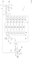
- FIG. 1 is a schematic view of a machine according to an exemplary embodiment of the invention.
- the hydrogen tank to be tested 30 is first subjected to a pressure resistance test under water. It is then dried and then flushed with nitrogen to remove all traces of oxygen from the tank. At the end of this operation, it is under a residual pressure of approximately 5 bars of nitrogen.
- Machine 1 represented in [ Fig. 1 ] comprises a first tank R2 supplied with a mixture of nitrogen and helium at 2% helium under a pressure of 40 bars from a supply circuit 3 comprising a pump 4 and a mixer 5 supplied by a nitrogen circuit 6 and a helium circuit 7.
- the helium content at the outlet of the mixer is measured by an analyzer 8 and the proportions of nitrogen and helium are adjusted with regulating valves 9, 10.
- Valve 11 is closed during the filling phase of tank R2, as is valve 13 located at the tank outlet.
- Machine 1 includes a set of complementary tanks, six tanks R3 to R8 in this exemplary embodiment, intended to receive the tracer gas at different and higher pressures.
- a compressor 12 makes it possible to supply these tanks with tracer gas from that available in tank R2 by raising its pressure from 40 bars to 718 bars.
- Tanks R3 to R8 are supplied with gas by opening an inlet valve 14 connected to an outlet of the compressor 12, the inlet valve 14 being closed when the target pressure is reached in the tank, the tank pressure being measured by a pressure gauge 15.
- the last tank R8 is at a nominal pressure of 718 bars, higher than that of 600 bars of tank 30 to be tested, the others are at decreasing intermediate nominal pressures, down to 40 bars for tank R2.
- test tank 30 To fill the test tank 30 with tracer gas at 600 bars, it is successively connected to each of the tanks R3 to R8 using a transfer circuit 16 connected to the outlets of the tanks R3 to R8, by opening an outlet valve 17 of the tank concerned, starting with the tank R3 at the lowest pressure. Once a desired pressure is reached in the tank 30 to be tested, the valve 17 of the tank concerned is closed and that of the next tank is opened to increase the pressure in the tank to be tested. When the last tank R8 reaches 718 bars, its outlet valve 17 is opened until the pressure in the test tank 30 is 600 bars. Once this pressure is reached, the tank R8 is isolated by closing its outlet valve 17. exit 17.
- the helium content in the tank to be tested is checked with an analyzer 28 and helium is topped up if necessary from a helium buffer tank 18 at 750 bars.
- the buffer tank 18 is supplied with helium from a helium supply tank 19 by means of a booster 20.
- the outlet valve 17 of the tank R7 is opened in order to connect it to the test tank by means of the transfer circuit 16. Due to a higher pressure in the test tank 30, part of the tracer gas which was in this tank is transferred into the tank R7. It is possible to wait until the pressures between the test tank 30 and the tank R7 have equalized, but this may take too long, which is detrimental to the machine cycle time. It is therefore advantageous to stop the transfer between the two tanks when the pressure difference between them has reached a target value.
- Tank R7 is then isolated by closing its outlet valve 17 and test tank 30 is connected to tank R6 by means of transfer circuit 16 by opening its outlet valve 17. Once the target pressure difference is reached between these two tanks, tank R6 is isolated by closing its outlet valve 17 and the same procedure is carried out successively for tanks R5 to R2 so as to successively transfer tracer gas contained in test tank 30 into these tanks.
- the machine 1 may include a return circuit 24 connecting the tank to be tested 30 and the suction of the pump 4 allowing the tracer gas remaining in the tank 30 to be transferred to the tank R2.
- a valve 22 is arranged on the side of the machine to be tested 30 to isolate the return circuit 24. During this step, the mixer 5 is isolated by a valve 25. At the end of this operation, after closing the valve 22, a valve 26 allows the tank 30 to be returned to atmospheric pressure before it is separated from the machine.
- the machine may not include the return circuit 24 and opening the valve 22 may simply discharge the remainder of the test gas contained in the tested tank to the atmosphere and return its pressure to atmospheric pressure.
- the table below illustrates an example of operating points of a machine according to the [ Fig. 1 ], in which the nominal pressures of the tanks at the start of the test cycle of a tank 30 are indicated in column A, and in column B the tank pressures after filling tank 30 to be tested, in column C the volume brought to tank 30 by each tank, in column D the tank pressures after recovery of gas from the tested tank, in column E the volume recovered from tank 30 by each tank, and in column F, the volume of gas to be brought to the tanks to return to the initial state and start a new test cycle.
- Test tank 30 was filled from tanks R3 to R8 with a total tracer gas volume of 142.8 Nm 3 . After the test, 127.7 Nm 3 of tracer gas was recovered from test tank 30, representing 89% of the tracer gas. 75.6 Nm 3 of tracer gas was required to be added to tanks R3 to R8 from tank R2, but only 47.4 Nm 3 was supplied by mixing station 5, the difference having been recovered from tank R2 when the test tank was emptied. Only 16.4 Nm 3 would be lost if the tank were to be connected to the atmosphere by opening valve 26, corresponding to the 68 bar remaining in the test tank after emptying. However, it is advantageous to recover this gas through the return circuit 24.
- the filling with tracer gas can follow a strategy defined according to the pressures available in tanks R3 to R8.
- the test pressure is low, for example 400 bars
- only the first tanks R3 to R6 will be used and the gas top-up of these tanks after the test can be carried out from tank R7.
- the same procedure will be followed for the following tests as long as that the pressure in tank R7 allows it.
- the top-up of tanks R3 to R6 will be carried out from tank R8.
- a tank R7 and R8 has insufficient pressure for top-up, it joins the batch of tanks used for filling the tank to be tested. The distribution of pressures in these tanks is adjusted each time a new tank joins the batch of tanks used for filling in order to optimize the energy efficiency of the test process.
- the number of tanks R2 to R8 is optimized in particular according to the tank test pressure, according to the variety of tanks to be tested in terms of test pressure and volume and according to the cycle time required for testing a tank. Pressure losses in the circuits and the Kv values of the valves are also taken into account, as these have an impact on the tracer gas flows. Kv expresses the flow rate in a valve with a pressure drop of one bar; if it is a control valve, the Kv value will be different depending on the opening level of the valve.
- Hydrogen tanks 30 are generally equipped with an "overflow" type valve 27. For safety reasons, this valve closes when the flow rate exceeds a defined value. The maximum flow rate allowed when emptying a tested tank is thus limited by this valve and must be considered for the sizing of the machine.
- the volume of tanks R2 to R8 is chosen based on these parameters, as not all tanks necessarily have the same volume.
Landscapes
- Engineering & Computer Science (AREA)
- Mechanical Engineering (AREA)
- General Engineering & Computer Science (AREA)
- Filling Or Discharging Of Gas Storage Vessels (AREA)
- Filling Of Jars Or Cans And Processes For Cleaning And Sealing Jars (AREA)
- Basic Packing Technique (AREA)
- Vacuum Packaging (AREA)
Claims (3)
- Verfahren zum Füllen eines Gehäuses (30) mit einem Fluid, bis ein Zieldruck erreicht ist, dann Entleeren des Gehäuses zu gegebener Zeit, dadurch gekennzeichnet, dass das Füllen von einer ersten Anzahl von Behältern (R3, R4, R5, R6, R7, R8) mit unterschiedlichen Drücken aufeinanderfolgend von dem Behälter (R3) mit dem niedrigsten Druck zu dem Behälter (R8) mit dem höchsten Druck erfolgt, und dass das Entleeren durch Übertragen des Inhalts von dem Gehäuse (30) an eine zweite Anzahl von Behältern (R2, R3, R4, R5, R6, R7) aufeinanderfolgend an den Behälter (R7) mit dem höchsten Druck zu dem Behälter (R2) mit dem niedrigsten Druck erfolgt.
- Verfahren nach Anspruch 1, dadurch gekennzeichnet, dass das Entleeren in einer zweiten Vielzahl von Behältern erfolgt, die aus Behältern der ersten Vielzahl von Behältern zusammengesetzt ist.
- Verfahren nach Anspruch 2, dadurch gekennzeichnet, dass nach dem Entleeren eine Fluidersetzung in der zweiten Vielzahl von Behältern, die dann als die erste Vielzahl von Behältern für eine Neufüllung eines Gehäuses verwendet wird, ausgeführt wird.
Applications Claiming Priority (2)
| Application Number | Priority Date | Filing Date | Title |
|---|---|---|---|
| FR2114512A FR3131362B1 (fr) | 2021-12-24 | 2021-12-24 | Dispositif et procédé de remplissage d’une enceinte par un fluide sous pression puis de vidange de celle-ci avec récupération du fluide |
| PCT/EP2022/087625 WO2023118513A1 (fr) | 2021-12-24 | 2022-12-22 | Dispositif et procédé de remplissage d'une enceinte par un fluide sous pression puis de vidange de celle-ci avec récupération du fluide |
Publications (3)
| Publication Number | Publication Date |
|---|---|
| EP4453467A1 EP4453467A1 (de) | 2024-10-30 |
| EP4453467C0 EP4453467C0 (de) | 2025-06-25 |
| EP4453467B1 true EP4453467B1 (de) | 2025-06-25 |
Family
ID=80933280
Family Applications (1)
| Application Number | Title | Priority Date | Filing Date |
|---|---|---|---|
| EP22843347.0A Active EP4453467B1 (de) | 2021-12-24 | 2022-12-22 | Vorrichtung und verfahren zum füllen eines raumes mit einem unter druck stehenden fluid und dann zum entleeren dieses raumes mit rückgewinnung des fluids |
Country Status (8)
| Country | Link |
|---|---|
| US (1) | US20250137590A1 (de) |
| EP (1) | EP4453467B1 (de) |
| JP (1) | JP2025500486A (de) |
| KR (1) | KR20240136987A (de) |
| CN (1) | CN118715395A (de) |
| FR (1) | FR3131362B1 (de) |
| MX (1) | MX2024007882A (de) |
| WO (1) | WO2023118513A1 (de) |
Families Citing this family (2)
| Publication number | Priority date | Publication date | Assignee | Title |
|---|---|---|---|---|
| WO2025135447A1 (ko) | 2023-12-22 | 2025-06-26 | 주식회사 엘지에너지솔루션 | 배터리 셀, 이를 포함하는 배터리 팩, 자동차 및 이의 제조방법 |
| DE102024101156A1 (de) * | 2024-01-16 | 2025-07-17 | Voith Hystech Gmbh | Verfahren Vorrichtung zur Dichtheitsprüfung von Drucktanks |
Family Cites Families (5)
| Publication number | Priority date | Publication date | Assignee | Title |
|---|---|---|---|---|
| JP2500488B2 (ja) * | 1991-02-08 | 1996-05-29 | ヤマハ株式会社 | 漏洩試験方法及び漏洩試験装置 |
| US6530264B1 (en) * | 2000-11-16 | 2003-03-11 | Autoliv Asp, Inc. | Detection systems and methods |
| WO2008109006A2 (en) * | 2007-03-02 | 2008-09-12 | Enersea Transport Llc | Storing, transporting and handling compressed fluids |
| CN104075106B (zh) * | 2014-06-24 | 2016-02-10 | 江苏天舒电器有限公司 | 一种充氮保压抽真空设备的控制方法及其控制装置 |
| US20160116364A1 (en) * | 2014-10-24 | 2016-04-28 | Air Products And Chemicals, Inc. | Leak Test Apparatus and Method |
-
2021
- 2021-12-24 FR FR2114512A patent/FR3131362B1/fr active Active
-
2022
- 2022-12-22 MX MX2024007882A patent/MX2024007882A/es unknown
- 2022-12-22 CN CN202280085592.4A patent/CN118715395A/zh active Pending
- 2022-12-22 US US18/723,247 patent/US20250137590A1/en active Pending
- 2022-12-22 KR KR1020247024802A patent/KR20240136987A/ko active Pending
- 2022-12-22 EP EP22843347.0A patent/EP4453467B1/de active Active
- 2022-12-22 JP JP2024538276A patent/JP2025500486A/ja active Pending
- 2022-12-22 WO PCT/EP2022/087625 patent/WO2023118513A1/fr not_active Ceased
Also Published As
| Publication number | Publication date |
|---|---|
| EP4453467C0 (de) | 2025-06-25 |
| KR20240136987A (ko) | 2024-09-19 |
| MX2024007882A (es) | 2024-09-10 |
| FR3131362B1 (fr) | 2024-07-05 |
| US20250137590A1 (en) | 2025-05-01 |
| CN118715395A (zh) | 2024-09-27 |
| FR3131362A1 (fr) | 2023-06-30 |
| WO2023118513A1 (fr) | 2023-06-29 |
| EP4453467A1 (de) | 2024-10-30 |
| JP2025500486A (ja) | 2025-01-09 |
Similar Documents
| Publication | Publication Date | Title |
|---|---|---|
| EP4453467B1 (de) | Vorrichtung und verfahren zum füllen eines raumes mit einem unter druck stehenden fluid und dann zum entleeren dieses raumes mit rückgewinnung des fluids | |
| CA2635970C (fr) | Procede et dispositif de remplissage de conteneurs de gaz sous pression | |
| EP3280946B1 (de) | Station und verfahren zur tankbefüllung mit einem flüssiggas | |
| EP3690303B1 (de) | Verfahren und vorrichtung zum füllen eines flüssiggasbehälters | |
| EP4090880B1 (de) | Anlage und verfahren zum lagern und verteilen eines kryogenen fluids | |
| EP2174057A1 (de) | Verfahren zum füllen eines tanks mit unter druck stehendem gas | |
| EP0388332A1 (de) | Gerät zur Druckgasinjektion in grossen Mengen in einen geschlossenen Behälter mit Rückgewinnung des Gases | |
| CN112983678B (zh) | 推进剂输送装置和推进剂加注方法 | |
| FR3106393A1 (fr) | Station et un procédé de remplissage de réservoir(s). | |
| EP3892910B1 (de) | Füllvorrichtung für unter druck stehende gastanks | |
| EP3105808B1 (de) | Spülungskreislauf einer brennstoffzelle | |
| FR3002681A1 (fr) | Systeme d'injection de securite passif utilisant un reservoir d'injection de securite | |
| WO2015118261A1 (fr) | Procede d'approvisionnement d'une station de distribution d'hydrogene gazeux a pression constante - station associee | |
| CH627247A5 (de) | ||
| FR3109202A1 (fr) | Dispositif et procédé de remplissage de réservoirs de gaz sous pression. | |
| EP0949448A1 (de) | Anlage und Verfahren zum Abfüllen von Flaschen | |
| WO2005075882A1 (fr) | Station de remplissage de dioxyde de carbone liquide vers un reservoir mobile | |
| CN109975126A (zh) | 一种航天器化学推进系统推进剂贮存模块极性测试方法 | |
| EP3488139B1 (de) | Modul und system zur druckentlastung eines kryogenen tanks | |
| FR3104672A3 (fr) | Procédé de remplissage d’un ensemble de plusieurs stockages de gaz sous pression | |
| EP0201374A1 (de) | Hydraulisches Antriebsystem für ein Teil in einer Rakete | |
| EP1789722A2 (de) | Station zum einfüllen von kohlendioxid in einen mobilen tank | |
| EP3232113A1 (de) | Automatisiertes verfahren und automatisierte station zur gravimetrischen verteilung von kondensiertem gas in flüssigzustand | |
| FR3109980A3 (fr) | Dispositif de remplissage de réservoirs de gaz sous pression | |
| FR3130264A1 (fr) | Procede de remplissage d’un reservoir au moyen d’un adaptateur de remplissage |
Legal Events
| Date | Code | Title | Description |
|---|---|---|---|
| STAA | Information on the status of an ep patent application or granted ep patent |
Free format text: STATUS: UNKNOWN |
|
| STAA | Information on the status of an ep patent application or granted ep patent |
Free format text: STATUS: THE INTERNATIONAL PUBLICATION HAS BEEN MADE |
|
| PUAI | Public reference made under article 153(3) epc to a published international application that has entered the european phase |
Free format text: ORIGINAL CODE: 0009012 |
|
| STAA | Information on the status of an ep patent application or granted ep patent |
Free format text: STATUS: REQUEST FOR EXAMINATION WAS MADE |
|
| 17P | Request for examination filed |
Effective date: 20240617 |
|
| AK | Designated contracting states |
Kind code of ref document: A1 Designated state(s): AL AT BE BG CH CY CZ DE DK EE ES FI FR GB GR HR HU IE IS IT LI LT LU LV MC ME MK MT NL NO PL PT RO RS SE SI SK SM TR |
|
| DAV | Request for validation of the european patent (deleted) | ||
| DAX | Request for extension of the european patent (deleted) | ||
| GRAP | Despatch of communication of intention to grant a patent |
Free format text: ORIGINAL CODE: EPIDOSNIGR1 |
|
| STAA | Information on the status of an ep patent application or granted ep patent |
Free format text: STATUS: GRANT OF PATENT IS INTENDED |
|
| INTG | Intention to grant announced |
Effective date: 20250408 |
|
| GRAS | Grant fee paid |
Free format text: ORIGINAL CODE: EPIDOSNIGR3 |
|
| GRAA | (expected) grant |
Free format text: ORIGINAL CODE: 0009210 |
|
| STAA | Information on the status of an ep patent application or granted ep patent |
Free format text: STATUS: THE PATENT HAS BEEN GRANTED |
|
| AK | Designated contracting states |
Kind code of ref document: B1 Designated state(s): AL AT BE BG CH CY CZ DE DK EE ES FI FR GB GR HR HU IE IS IT LI LT LU LV MC ME MK MT NL NO PL PT RO RS SE SI SK SM TR |
|
| REG | Reference to a national code |
Ref country code: GB Ref legal event code: FG4D Free format text: NOT ENGLISH |
|
| REG | Reference to a national code |
Ref country code: CH Ref legal event code: EP |
|
| REG | Reference to a national code |
Ref country code: CH Ref legal event code: EP |
|
| REG | Reference to a national code |
Ref country code: IE Ref legal event code: FG4D Free format text: LANGUAGE OF EP DOCUMENT: FRENCH |
|
| REG | Reference to a national code |
Ref country code: DE Ref legal event code: R096 Ref document number: 602022016615 Country of ref document: DE |
|
| U01 | Request for unitary effect filed |
Effective date: 20250702 |
|
| U07 | Unitary effect registered |
Designated state(s): AT BE BG DE DK EE FI FR IT LT LU LV MT NL PT RO SE SI Effective date: 20250711 |
|
| PG25 | Lapsed in a contracting state [announced via postgrant information from national office to epo] |
Ref country code: NO Free format text: LAPSE BECAUSE OF FAILURE TO SUBMIT A TRANSLATION OF THE DESCRIPTION OR TO PAY THE FEE WITHIN THE PRESCRIBED TIME-LIMIT Effective date: 20250925 Ref country code: GR Free format text: LAPSE BECAUSE OF FAILURE TO SUBMIT A TRANSLATION OF THE DESCRIPTION OR TO PAY THE FEE WITHIN THE PRESCRIBED TIME-LIMIT Effective date: 20250926 |
|
| PG25 | Lapsed in a contracting state [announced via postgrant information from national office to epo] |
Ref country code: HR Free format text: LAPSE BECAUSE OF FAILURE TO SUBMIT A TRANSLATION OF THE DESCRIPTION OR TO PAY THE FEE WITHIN THE PRESCRIBED TIME-LIMIT Effective date: 20250625 |
|
| PG25 | Lapsed in a contracting state [announced via postgrant information from national office to epo] |
Ref country code: RS Free format text: LAPSE BECAUSE OF FAILURE TO SUBMIT A TRANSLATION OF THE DESCRIPTION OR TO PAY THE FEE WITHIN THE PRESCRIBED TIME-LIMIT Effective date: 20250925 |
|
| U20 | Renewal fee for the european patent with unitary effect paid |
Year of fee payment: 4 Effective date: 20251119 |
|
| PG25 | Lapsed in a contracting state [announced via postgrant information from national office to epo] |
Ref country code: IS Free format text: LAPSE BECAUSE OF FAILURE TO SUBMIT A TRANSLATION OF THE DESCRIPTION OR TO PAY THE FEE WITHIN THE PRESCRIBED TIME-LIMIT Effective date: 20251025 |
|
| PG25 | Lapsed in a contracting state [announced via postgrant information from national office to epo] |
Ref country code: SM Free format text: LAPSE BECAUSE OF FAILURE TO SUBMIT A TRANSLATION OF THE DESCRIPTION OR TO PAY THE FEE WITHIN THE PRESCRIBED TIME-LIMIT Effective date: 20250625 |
|
| PG25 | Lapsed in a contracting state [announced via postgrant information from national office to epo] |
Ref country code: CZ Free format text: LAPSE BECAUSE OF FAILURE TO SUBMIT A TRANSLATION OF THE DESCRIPTION OR TO PAY THE FEE WITHIN THE PRESCRIBED TIME-LIMIT Effective date: 20250625 |
|
| PG25 | Lapsed in a contracting state [announced via postgrant information from national office to epo] |
Ref country code: PL Free format text: LAPSE BECAUSE OF FAILURE TO SUBMIT A TRANSLATION OF THE DESCRIPTION OR TO PAY THE FEE WITHIN THE PRESCRIBED TIME-LIMIT Effective date: 20250625 |
|
| PG25 | Lapsed in a contracting state [announced via postgrant information from national office to epo] |
Ref country code: SK Free format text: LAPSE BECAUSE OF FAILURE TO SUBMIT A TRANSLATION OF THE DESCRIPTION OR TO PAY THE FEE WITHIN THE PRESCRIBED TIME-LIMIT Effective date: 20250625 |
|
| PG25 | Lapsed in a contracting state [announced via postgrant information from national office to epo] |
Ref country code: ES Free format text: LAPSE BECAUSE OF FAILURE TO SUBMIT A TRANSLATION OF THE DESCRIPTION OR TO PAY THE FEE WITHIN THE PRESCRIBED TIME-LIMIT Effective date: 20250625 |