EP4452823B1 - Ausgabevorrichtung für kohlensäurehaltige getränke - Google Patents
Ausgabevorrichtung für kohlensäurehaltige getränke Download PDFInfo
- Publication number
- EP4452823B1 EP4452823B1 EP23734897.4A EP23734897A EP4452823B1 EP 4452823 B1 EP4452823 B1 EP 4452823B1 EP 23734897 A EP23734897 A EP 23734897A EP 4452823 B1 EP4452823 B1 EP 4452823B1
- Authority
- EP
- European Patent Office
- Prior art keywords
- soda
- compensator
- carbonated beverage
- beverage dispenser
- additive
- Prior art date
- Legal status (The legal status is an assumption and is not a legal conclusion. Google has not performed a legal analysis and makes no representation as to the accuracy of the status listed.)
- Active
Links
Images


Classifications
-
- B—PERFORMING OPERATIONS; TRANSPORTING
- B67—OPENING, CLOSING OR CLEANING BOTTLES, JARS OR SIMILAR CONTAINERS; LIQUID HANDLING
- B67D—DISPENSING, DELIVERING OR TRANSFERRING LIQUIDS, NOT OTHERWISE PROVIDED FOR
- B67D1/00—Apparatus or devices for dispensing beverages on draught
- B67D1/08—Details
- B67D1/12—Flow or pressure control devices or systems, e.g. valves, gas pressure control, level control in storage containers
- B67D1/1277—Flow control valves
- B67D1/1279—Flow control valves regulating the flow
- B67D1/1281—Flow control valves regulating the flow responsive to pressure
-
- B—PERFORMING OPERATIONS; TRANSPORTING
- B67—OPENING, CLOSING OR CLEANING BOTTLES, JARS OR SIMILAR CONTAINERS; LIQUID HANDLING
- B67D—DISPENSING, DELIVERING OR TRANSFERRING LIQUIDS, NOT OTHERWISE PROVIDED FOR
- B67D1/00—Apparatus or devices for dispensing beverages on draught
- B67D1/0015—Apparatus or devices for dispensing beverages on draught the beverage being prepared by mixing at least two liquid components
- B67D1/0021—Apparatus or devices for dispensing beverages on draught the beverage being prepared by mixing at least two liquid components the components being mixed at the time of dispensing, i.e. post-mix dispensers
-
- B—PERFORMING OPERATIONS; TRANSPORTING
- B67—OPENING, CLOSING OR CLEANING BOTTLES, JARS OR SIMILAR CONTAINERS; LIQUID HANDLING
- B67D—DISPENSING, DELIVERING OR TRANSFERRING LIQUIDS, NOT OTHERWISE PROVIDED FOR
- B67D1/00—Apparatus or devices for dispensing beverages on draught
- B67D1/0042—Details of specific parts of the dispensers
- B67D1/0043—Mixing devices for liquids
- B67D1/0044—Mixing devices for liquids for mixing inside the dispensing nozzle
- B67D1/0046—Mixing chambers
-
- B—PERFORMING OPERATIONS; TRANSPORTING
- B67—OPENING, CLOSING OR CLEANING BOTTLES, JARS OR SIMILAR CONTAINERS; LIQUID HANDLING
- B67D—DISPENSING, DELIVERING OR TRANSFERRING LIQUIDS, NOT OTHERWISE PROVIDED FOR
- B67D1/00—Apparatus or devices for dispensing beverages on draught
- B67D1/0042—Details of specific parts of the dispensers
- B67D1/0057—Carbonators
- B67D1/0058—In-line carbonators
- B67D1/0059—In-line carbonators in combination with a mixer tap
-
- B—PERFORMING OPERATIONS; TRANSPORTING
- B67—OPENING, CLOSING OR CLEANING BOTTLES, JARS OR SIMILAR CONTAINERS; LIQUID HANDLING
- B67D—DISPENSING, DELIVERING OR TRANSFERRING LIQUIDS, NOT OTHERWISE PROVIDED FOR
- B67D1/00—Apparatus or devices for dispensing beverages on draught
- B67D1/0042—Details of specific parts of the dispensers
- B67D1/0057—Carbonators
- B67D1/0061—Carbonators with cooling means
- B67D1/0062—Carbonators with cooling means inside the carbonator
-
- B—PERFORMING OPERATIONS; TRANSPORTING
- B67—OPENING, CLOSING OR CLEANING BOTTLES, JARS OR SIMILAR CONTAINERS; LIQUID HANDLING
- B67D—DISPENSING, DELIVERING OR TRANSFERRING LIQUIDS, NOT OTHERWISE PROVIDED FOR
- B67D1/00—Apparatus or devices for dispensing beverages on draught
- B67D1/08—Details
-
- B—PERFORMING OPERATIONS; TRANSPORTING
- B67—OPENING, CLOSING OR CLEANING BOTTLES, JARS OR SIMILAR CONTAINERS; LIQUID HANDLING
- B67D—DISPENSING, DELIVERING OR TRANSFERRING LIQUIDS, NOT OTHERWISE PROVIDED FOR
- B67D1/00—Apparatus or devices for dispensing beverages on draught
- B67D1/08—Details
- B67D1/0857—Cooling arrangements
-
- B—PERFORMING OPERATIONS; TRANSPORTING
- B67—OPENING, CLOSING OR CLEANING BOTTLES, JARS OR SIMILAR CONTAINERS; LIQUID HANDLING
- B67D—DISPENSING, DELIVERING OR TRANSFERRING LIQUIDS, NOT OTHERWISE PROVIDED FOR
- B67D1/00—Apparatus or devices for dispensing beverages on draught
- B67D1/08—Details
- B67D1/12—Flow or pressure control devices or systems, e.g. valves, gas pressure control, level control in storage containers
- B67D1/14—Reducing valves or control taps
- B67D1/1405—Control taps
- B67D1/145—Control taps comprising a valve shutter movable in a direction perpendicular to the valve seat
- B67D1/1455—Control taps comprising a valve shutter movable in a direction perpendicular to the valve seat the valve shutter being opened in the same direction as the liquid flow
- B67D1/1461—Control taps comprising a valve shutter movable in a direction perpendicular to the valve seat the valve shutter being opened in the same direction as the liquid flow the valve shutter being integral with a compensator
-
- B—PERFORMING OPERATIONS; TRANSPORTING
- B67—OPENING, CLOSING OR CLEANING BOTTLES, JARS OR SIMILAR CONTAINERS; LIQUID HANDLING
- B67D—DISPENSING, DELIVERING OR TRANSFERRING LIQUIDS, NOT OTHERWISE PROVIDED FOR
- B67D1/00—Apparatus or devices for dispensing beverages on draught
- B67D1/08—Details
- B67D1/12—Flow or pressure control devices or systems, e.g. valves, gas pressure control, level control in storage containers
- B67D1/14—Reducing valves or control taps
- B67D1/1405—Control taps
- B67D1/145—Control taps comprising a valve shutter movable in a direction perpendicular to the valve seat
- B67D1/1466—Control taps comprising a valve shutter movable in a direction perpendicular to the valve seat the valve shutter being opened in a direction opposite to the liquid flow
- B67D1/1472—Control taps comprising a valve shutter movable in a direction perpendicular to the valve seat the valve shutter being opened in a direction opposite to the liquid flow the valve shutter being integral with a compensator
-
- B—PERFORMING OPERATIONS; TRANSPORTING
- B67—OPENING, CLOSING OR CLEANING BOTTLES, JARS OR SIMILAR CONTAINERS; LIQUID HANDLING
- B67D—DISPENSING, DELIVERING OR TRANSFERRING LIQUIDS, NOT OTHERWISE PROVIDED FOR
- B67D1/00—Apparatus or devices for dispensing beverages on draught
- B67D1/0042—Details of specific parts of the dispensers
- B67D1/0081—Dispensing valves
- B67D1/0082—Dispensing valves entirely mechanical
-
- B—PERFORMING OPERATIONS; TRANSPORTING
- B67—OPENING, CLOSING OR CLEANING BOTTLES, JARS OR SIMILAR CONTAINERS; LIQUID HANDLING
- B67D—DISPENSING, DELIVERING OR TRANSFERRING LIQUIDS, NOT OTHERWISE PROVIDED FOR
- B67D1/00—Apparatus or devices for dispensing beverages on draught
- B67D1/08—Details
- B67D1/0888—Means comprising electronic circuitry (e.g. control panels, switching or controlling means)
-
- B—PERFORMING OPERATIONS; TRANSPORTING
- B67—OPENING, CLOSING OR CLEANING BOTTLES, JARS OR SIMILAR CONTAINERS; LIQUID HANDLING
- B67D—DISPENSING, DELIVERING OR TRANSFERRING LIQUIDS, NOT OTHERWISE PROVIDED FOR
- B67D1/00—Apparatus or devices for dispensing beverages on draught
- B67D1/08—Details
- B67D1/12—Flow or pressure control devices or systems, e.g. valves, gas pressure control, level control in storage containers
- B67D1/1202—Flow control, e.g. for controlling total amount or mixture ratio of liquids to be dispensed
- B67D1/1204—Flow control, e.g. for controlling total amount or mixture ratio of liquids to be dispensed for ratio control purposes
-
- B—PERFORMING OPERATIONS; TRANSPORTING
- B67—OPENING, CLOSING OR CLEANING BOTTLES, JARS OR SIMILAR CONTAINERS; LIQUID HANDLING
- B67D—DISPENSING, DELIVERING OR TRANSFERRING LIQUIDS, NOT OTHERWISE PROVIDED FOR
- B67D1/00—Apparatus or devices for dispensing beverages on draught
- B67D1/08—Details
- B67D1/12—Flow or pressure control devices or systems, e.g. valves, gas pressure control, level control in storage containers
- B67D1/1277—Flow control valves
- B67D1/1279—Flow control valves regulating the flow
-
- B—PERFORMING OPERATIONS; TRANSPORTING
- B67—OPENING, CLOSING OR CLEANING BOTTLES, JARS OR SIMILAR CONTAINERS; LIQUID HANDLING
- B67D—DISPENSING, DELIVERING OR TRANSFERRING LIQUIDS, NOT OTHERWISE PROVIDED FOR
- B67D1/00—Apparatus or devices for dispensing beverages on draught
- B67D1/08—Details
- B67D1/12—Flow or pressure control devices or systems, e.g. valves, gas pressure control, level control in storage containers
- B67D1/1284—Ratio control
- B67D1/1295—Ratio defined by setting flow controllers
-
- B—PERFORMING OPERATIONS; TRANSPORTING
- B67—OPENING, CLOSING OR CLEANING BOTTLES, JARS OR SIMILAR CONTAINERS; LIQUID HANDLING
- B67D—DISPENSING, DELIVERING OR TRANSFERRING LIQUIDS, NOT OTHERWISE PROVIDED FOR
- B67D1/00—Apparatus or devices for dispensing beverages on draught
- B67D1/08—Details
- B67D1/12—Flow or pressure control devices or systems, e.g. valves, gas pressure control, level control in storage containers
- B67D1/14—Reducing valves or control taps
- B67D1/1405—Control taps
- B67D1/145—Control taps comprising a valve shutter movable in a direction perpendicular to the valve seat
-
- B—PERFORMING OPERATIONS; TRANSPORTING
- B67—OPENING, CLOSING OR CLEANING BOTTLES, JARS OR SIMILAR CONTAINERS; LIQUID HANDLING
- B67D—DISPENSING, DELIVERING OR TRANSFERRING LIQUIDS, NOT OTHERWISE PROVIDED FOR
- B67D1/00—Apparatus or devices for dispensing beverages on draught
- B67D2001/0093—Valves
-
- B—PERFORMING OPERATIONS; TRANSPORTING
- B67—OPENING, CLOSING OR CLEANING BOTTLES, JARS OR SIMILAR CONTAINERS; LIQUID HANDLING
- B67D—DISPENSING, DELIVERING OR TRANSFERRING LIQUIDS, NOT OTHERWISE PROVIDED FOR
- B67D1/00—Apparatus or devices for dispensing beverages on draught
- B67D1/08—Details
- B67D1/12—Flow or pressure control devices or systems, e.g. valves, gas pressure control, level control in storage containers
- B67D1/14—Reducing valves or control taps
- B67D2001/1494—Taps with means for adjusting the position of a compensator from outside
Definitions
- the present disclosure relates to a carbonated beverage dispenser.
- Carbonated beverages are beverages that contain dissolved carbon dioxide.
- An example of a carbonated beverage is a soda drink, which comprises a soda base (i.e., carbonated water) mixed with additives.
- Tonic water is one such soda drink.
- Tonic water has acquired a huge amount of popularity in recent years, particularly in view of a revival of cocktails such as a gin and tonic.
- Tonic water is often flavoured with additives in the form of citric acid, quinine and sugar which give it a distinct sour-bitter-sweet taste.
- Other flavourings such as botanicals or fruit flavourings may be added to provide flavoured tonic waters.
- a soda gun typically involves mixing soda with at least one additive, and then dispensing the mixture into a drinking receptacle for consumption.
- Different additives can be selected and added to select different carbonated beverages. Since only one tool, i.e., the soda gun, can be used to dispense a large variety of different carbonated beverages, there are huge savings in space at the bar, and in time for the barperson.
- a high-quality tonic water typically has a high carbonation level: higher than the carbonation level of many other carbonated beverages.
- premium tonic waters and other premium (non-alcoholic) soda drinks have a carbonation of at least 4 volumes of CO 2
- typical non-premium soda drinks and non-premium tonic waters have a carbonation of 2.5 - 3.5 volumes of CO 2
- beers typically 2.2 - 2.6 volumes of CO 2 .
- Carbonation can be maintained at a relatively high level when the tonic water is stored in bottles or cans in relatively small quantities.
- dispensing large volumes of tonic water through a soda gun maintaining high carbonation levels is more challenging.
- EP 2933222 describes a compensator tap for beverages such as beers, which allows a gradual drop of pressure of the beer.
- the compensator is adjustable via a hand lever.
- GB2117094 describes a flow restrictor for a beer line, having a frusto-conical plug member that is adjustably located in a frusto-conical flow passage in a body part.
- the carbonated beverage dispenser according to the present invention aims to solve at least some of the problems associated with the prior art.
- a carbonated beverage dispenser for dispensing a carbonated beverage comprising soda and at least one additive
- the carbonated beverage dispenser comprising a compensator for regulating the flow rate of soda, the compensator comprising:
- Precise control of the gap between the inner body and the outer body in this way can be used to ensure a high level of carbonation in the dispensed soda drink.
- Such precise control is more important for soda drinks, compared to, say, beer, because soda is less viscous than beer, and because the carbonation requirements for high-quality soda are often higher than beer.
- the carbonated beverage dispenser is a soda drink dispenser for dispensing soda drinks, and in particular for dispensing non-alcoholic drinks.
- the first extent is optionally larger than to the second extent.
- the gap between the inner body and the outer body is fixed.
- the control element is optionally rotatable.
- the user input may be a rotation of the control element.
- control element takes the form of a differential screw.
- the differential screw may have a first portion comprising a first thread for engaging the outer body and a second portion comprising a second thread for engaging the inner body.
- the first thread may have a different thread pitch to the second thread.
- the first thread has a smaller thread pitch than the second thread.
- the first thread has a pitch of between 0.65 and 0.85 mm, and / or the second thread has a pitch of between 0.9 mm and 1.1 mm.
- the first thread has a pitch of 0.75 mm and the second thread has a pitch of 1.0 mm
- the inner body is moved 1.00 mm up relative to the differential screw. Accordingly, the inner body only moves 0.25 mm relative to the outer body.
- the first thread has an ISO Metric thread dimension M8, and the second thread has an ISO Metric thread dimension M6.
- control element For a full rotation of the control element, the control element preferably causes relative longitudinal displacement between the inner and outer bodies of between 0.20 mm and 0.30 mm.
- this relative longitudinal displacement between the inner and outer bodies brings about a change of a few microns in the gap between the inner body and the outer body, where said gap is measured at a right angle with respect to the outer surface of the inner body and/ or the inner surface of the outer body and/ or the flow of soda through said gap.
- the inner body may be non-rotational with respect to the outer body.
- control element comprises an engagement portion that protrudes out of the outer body to define an engagement feature for engagement by a user.
- the engagement portion preferably takes the form of a grip and may be provided at the first portion of the rotatable control element.
- Cooling the compensator further reduces outgassing in dispensed soda. Also, it helps to ensure a constant liquid velocity of the dispensed soda, and hence the liquid dispense volume is made more consistent.
- the cooling liquid may be the soda, which may be circulated through the cooling conduit before or after it is passed through the compensator chamber. Alternatively, instead of using recirculated soda, a cooling conduit separate to the compensator chamber can be used, with a separate cooling liquid.
- the outer body is made of a thermally conductive metal such as steel, although other metals or plastics may also be used. Plastic may be preferred because it results in a simplified manufacturing process and reduced costs - all plastic parts may be moulded separately and then welded together. Also, plastic has been found to ensure sufficient heat transfer, and it can be easier to achieve a much smoother finish on plastic parts than on metal counterparts.
- the inner body may be made of steel or plastic. Again, plastic may be preferred because it results in a simplified manufacturing process and reduced costs.
- the compensator may comprise a first region proximal to the inlet, a second region proximal to the outlet, and/ or a middle region therebetween.
- the first region may be an upstream region and the second region may be a downstream region of the compensator, relative to the direction of soda flow through the compensator.
- the upstream region is also arranged above the downstream region, since the direction of flow in this embodiment is downward, but this need not be the case and in other embodiments the flow may be in other directions, with the upstream and downstream regions arranged accordingly.
- a diameter of the inner body and a diameter of the compensator chamber are preferably approximately constant between the inlet and the middle region.
- the gap between the inner and outer bodies is fixed. This is because, regardless of any relative movement between the inner and outer bodies along longitudinal axis L, the gap between the two remains the same. This advantageously provides a fixed pressure drop to fluid passing over.
- the or a diameter of the inner body and the or a diameter of the compensator chamber increase at substantially the same fixed rate between the first and the second region.
- the gap between the inner and outer bodies is variable and changes in dependence on the relative lateral movement between the inner and outer bodies along longitudinal axis L.
- the pressure drop provided by the compensator can be precisely tuned. This variable pressure drop in the middle region ensures high precision in flow rate calibration.
- the or a diameter of the inner body and the or a diameter of the compensator chamber preferably decrease at different fixed rates between the middle region and the outlet.
- the gap between the inner and outer bodies increases moving down the longitudinal axis L.
- the fluid is advantageously decelerated without outgassing.
- the fluid can be dispensed at an appropriate rate without losing any carbonation.
- the inner body may be substantially cylindrical in the first region, substantially frustoconical in the middle region, and/ or substantially conical in the second region.
- an outer surface of the inner body, and/or an inner surface of the inlet and/ or an inner surface of the outlet has a maximum surface roughness of 0.1 microns Ra. This smoothness reduces nucleation sites for bubble formation, hence reduces outgassing in the dispensed soda.
- the carbonated beverage dispenser further comprises a soda delivery system comprising a chiller-carbonator for chilling and carbonating soda for the compensator.
- the soda delivery system further comprises a first soda delivery conduit for transporting soda from the chiller-carbonator to the cooling conduit for cooling the compensator.
- a first soda delivery conduit for transporting soda from the chiller-carbonator to the cooling conduit for cooling the compensator.
- chilled and carbonated soda water which can be regulated by the compensator and then dispensed, is used to cool the compensator itself.
- the soda delivery system may further comprise a third soda delivery conduit for transporting soda from the cooling conduit back to the chiller-carbonator for re-cooling and re-carbonisation.
- the soda delivery system may further comprise a second soda delivery conduit for transporting soda water from the chiller-carbonator to the compensator for flow-regulation, preferably when selectively operated by a user.
- the chiller-carbonator is preferably configured to pressurise soda to between 5.5 bar and 6.9 bar, and more preferably 6.2 bar.
- the soda is preferably pressured to between 80 and 100 PSI, and more preferably 90 PSI, i.e., between 5.5 bar and 6.9 bar, and more preferably 6.2 bar.
- An inner surface of the mixing chamber preferably has maximum roughness of 0.1 microns Ra. This smoothness reduces nucleation sites for bubble formation, hence reducing outgassing in the dispensed mixed soda.
- volume of mixing chamber is preferably sufficient such that the mixing chamber does not overflow depending on pour volume and dispense time.
- the first opening may be defined in an upper wall of the mixing chamber and/ or the at least one additive dispenser may be arranged above the mixing chamber.
- the additive dispensing system may comprise a plurality of additive dispensers each arranged to dispense an additive, a plurality of additive stores for storing each additive, and a plurality of additive delivery conduits for transporting additive from each additive store to the respective additive dispenser for dispensing.
- This configuration is preferable as it avoids contamination of additives, and hence reduces the need for cleaning.
- the carbonated beverage dispenser comprises a control unit for controlling the carbonated beverage dispenser during dispensing operations.
- the control unit is configured to control a dispensing flow of soda and additive such that, at the end of each dispensing operation, the last liquid that passes through the mixing chamber is soda, with no dispensed additive(s).
- the inlet of the compensator may be provided with a controller valve to control whether soda is delivered to the compensator, and then to the mixing chamber, and the or each additive dispensers may be provided with a dispenser valve and/ or pump to control whether additive is delivered to the mixing chamber.
- the control unit may be electrically coupled to the controller valve and/ or the or each dispenser valve.
- the mixing chamber is removable from the carbonated beverage dispenser. This allows the mixing chamber to be cleaned with ease.
- the mixing chamber is made of material such that it is fully dishwasher safe.
- the compensator may comprise a first connection part about the outlet.
- the mixing chamber may comprise a second connection part about the second opening.
- One of the first and second connection parts may be male and the other may be female.
- the first and second connection parts fit with a frictional fit.
- the carbonated beverage dispenser may comprise the or a control unit for controlling the operation of the carbonated beverage dispenser.
- the control unit is preferably configured to detect whether the mixing chamber has been removed from the carbonated beverage dispenser, and/ or to prevent the compensator and/ or the additive dispensing system from dispensing when the mixing chamber has been removed from the carbonated beverage dispenser.
- a magnetic interlock between the mixing chamber and the compensator can be used to facilitate this.
- the interlock may comprise a magnetic element on one or more of the first and second connection parts and may further comprise a sensor for sensing when the magnetic interlock is engaged.
- the sensor may be configured to communicate with the controller.
- the mixing chamber and the compensator can be attached by way of a rubber seal.
- the carbonated beverage dispenser may further comprise a carbonated beverage outlet for dispensing carbonated beverage from the mixing chamber.
- the carbonated beverage outlet is preferably connected to the mixing chamber such that both the mixing chamber and the carbonated beverage outlet are removable from the carbonated beverage dispenser.
- An inner surface of the carbonated beverage outlet preferably has a maximum surface roughness of 0.1 microns Ra. This smoothness reduces nucleation sites for bubble formation, hence reducing outgassing in the dispensed mixed soda.
- the carbonated beverage dispenser is illustrated in an up-right configuration, i.e., in the orientation in which the carbonated beverage dispenser would be used by a user.
- a longitudinal axis L of the compensator extends generally downwards.
- a longitudinal axis L of the compensator extends upwards at an angle to the vertical. All references to 'upper', 'lower', 'upward', 'downward', 'up', 'down' etc are with reference to these up-right orientations of the dispensers.
- An L, P co-ordinate system is used to refer to particular directions and axes relative to the compensator body, and the co-ordinate system is shown in the figures.
- Figure 1 shows a carbonated beverage dispenser 1, exemplified in the form of a (non-alcoholic) soda drink dispenser, according to an embodiment of the invention.
- the carbonated beverage dispenser 1 is configured to dispense carbonated beverages such as soda drinks including tonic water.
- a soda drink is any drink comprising soda, i.e., carbonated water, and at least one additive such as citric acid, sugar, quinine, botanicals and/ or other flavourings.
- At least one additive is preferably in the form of a water-based or alcohol-based liquid.
- the water-based liquid may contain sugar dissolved therein. Soda and additive(s) are mixed together to form any soda drink of choice.
- the carbonated beverage dispenser 1 comprises a compensator 100 that is configured to regulate the flow rate of liquids, i.e., the soda, passing therethrough. This is to ensure a high level of carbonation in the dispensed drink.
- This compensator 100 is particularly effective at providing resistance to offset the increased pressure needed for highly pressured drinks such as high-quality tonic waters. Without a compensator 100, a turbulent water out-flowing causes an unwanted and undesirable flattening in dispensed carbonated beverage.
- the carbonated beverage dispenser 1 comprises a soda delivery system 200 for delivering soda to the compensator 100, i.e. for flow regulation, an additive dispensing system 400 for dispensing at least one additive, and a mixing chamber 300 for receiving soda from the compensator 100 and at least one additive from the additive dispensing system 400, and mixing the soda with the at least one additive to form a soda drink (see Figure 1 ).
- the carbonated beverage dispenser 1 further comprises a carbonated beverage outlet 500 for dispensing the soda drink mixed in the mixing chamber 300 into, for example, a drinking receptacle (not shown) for consumption.
- the carbonated beverage dispenser 1 is also provided with a control unit (not shown) for controlling the operation thereof.
- Figure 3 shows the general flow of liquids through the carbonated beverage dispenser 1.
- Soda solid arrow D
- the additive dispensing system 400 dispenses at least one additive or additive mixture (dotted arrow A ) into the mixing chamber 300.
- the soda and the at least one additive are mixed together to form a soda drink.
- the soda drink (dashed arrow S ) then passes through the carbonated beverage outlet 500 for dispensing.
- the carbonated beverage dispenser 1 both (i) prepares the carbonated beverage (by mixing the soda and the additive(s) in together), and (ii) dispenses the carbonated beverage with minimal undesirable reduction in carbonation in the dispensed product. Since the soda and additive(s) are mixed before dispersion, there is the perception that only one liquid is being dispensed from the carbonated beverage dispenser 1, and so gives the same impression of when a bottle is used to serve a soda drink.
- the dispense unit 1, and especially the compensator arrangement is specifically designed to control the flow and carbonation of the soda drink during the dispense process, to maintain the premium characteristics of the soda drink, whilst allowing for high volume dispensing.
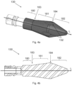
- the compensator 100 comprises an outer body 110 defining a compensator chamber 120, an inlet 140 for delivering soda into the compensator chamber 120, and an outlet 150 for delivering soda out of the compensator chamber 120.
- the compensator 100 also comprises an inner body 130 arranged within the compensator chamber 120 and between the inlet 140 and the outlet 150, as best seen in Figure 2 . Between the inner body 130 and the outer body 110, the compensator 100 defines a narrow gap 122 which regulates the flow rate of soda passing between the inlet 140 and the outlet 150.
- the size of the gap 122 affects the flow rate of the liquid through the compensator 100, which affects the amount of outgassing, and hence the carbonation of the final carbonated beverage. Careful control of the gap 122 is therefore important in controlling flow rate, and quality of the dispensed drink.
- control element 170 allows for precise control of the gap 122 between the inner body 130 and the outer body 110, and in particular allows for more precise control than if the control element only moved the inner body 130 or outer body 110 directly.
- the compensator 100 is able to ensure a high level of carbonation in the dispensed carbonated beverage. This is particularly important for soda, compared to, say, beer, because soda is less viscous than beer, such that the flow rate is more sensitive to changes in flow restriction, and because the carbonation requirements for soda are often higher than beer, meaning that quality is more affected by outgassing.
- the mixing chamber 300 comprises a first opening 305 and the additive dispensing system 400 comprises at least one additive dispenser 410 arranged to dispense at least one additive into the mixing chamber 300 through the first opening 305.
- a spacing S is provided between the at least one additive dispenser 410 and the mixing chamber 300.
- the at least one additive dispenser 410 never touch the liquids in mixing chamber 300, and so will never be contaminated thereby. Hence, the additive dispensers 410 do not need to be cleaned regularly.
- the inner and outer bodies 130, 110 of the compensator 100 both extend along longitudinal axis L, and are preferably symmetrical about that longitudinal axis L.
- the outer body 110 encloses the inner body 130 on all sides along the longitudinal axis L.
- the longitudinal axis L is arranged vertically.
- the inner body 130 and the compensator 120 extend substantially downwards, with parallel walls.
- a diameter of the inner body 130 and a diameter of the compensator chamber 120 are approximately constant when moving downwardly along the longitudinal axis L.
- the angle defined between the outer surface of the inner body 130 and the longitudinal axis L is substantially the same as the angle defined between the inner surface of the outer body 110 at each point along the L axis in the first region 180, and these angles are each approximately 0°.
- the gap 122 between the inner and outer bodies 130, 110 is fixed at around 70 microns. This is because, regardless of any relative movement between the inner and outer bodies 130, 110 along the longitudinal axis L, the gap 122 between the two remains the same. This advantageously provides a fixed pressure drop to fluid passing thereover.
- the inner body 130 and the compensator 120 flare out at the same fixed rate.
- the diameter of the inner body 130 and the diameter of the compensator chamber 120 increase at substantially the same fixed rate when moving downwardly along the longitudinal axis L.
- the angle defined between the outer surface of the inner body 130 and the longitudinal axis L is substantially the same as the angle defined between the inner surface of the outer body 110 at each point along the L axis in the middle region 181.
- the angle defined between the outer surface of the inner body 130 and the longitudinal axis L, and the angle defined between the inner surface of the outer body 110 and the longitudinal axis L are both fixed at between 5° and 15°, and preferably approximately 10°, at each point along the L axis.
- the gap 122 between the inner and outer bodies 130, 110 is variable in that it changes in dependence on the relative lateral positions of the inner and outer bodies 130, 110 along the longitudinal axis L. Hence, by way of longitudinal relative movement between the inner and outer bodies 130, 110, the gap 122 can be changed, and hence the pressure drop provided by the compensator can be precisely tuned.
- the gap 122 between the inner and outer bodies 130, 110 is constant along the length of the middle regions when the inner and outer bodies 130, 110 are fixed in place, and is altered only by relative movement between the inner and outer bodies 130.
- references to the gap 122 here are references to the perpendicular gap, i.e., the perpendicular spacing between the inner and outer bodies 130, 110, taken at right angles to the respective surfaces.
- the inner body 130 and the compensator 120 taper inward at different fixed rates.
- the diameter of the inner body 130 and of the compensator chamber 120 decrease at different fixed rates when moving downwardly along the longitudinal axis L.
- the angle defined between the outer surface of the inner body 130 and longitudinal axis L is slightly less than the angle defined between the inner surface of the outer body 110 at each point along the L axis in the second region 182 of the compensator 100, so that the gap 122 increases moving down the longitudinal axis L.
- the angle defined between the outer surface of the inner body 130 and the longitudinal axis L is fixed between 5° and 15°, and preferably approximately 10°, while the angle defined between the inner surface of the outer body 110 and the longitudinal axis L is fixed between 15° and 25°, and preferably approximately 20°.
- the inner body 130 is substantially cylindrical in the first region 180, substantially frustoconical in the middle region 181, and substantially conical in the second region 182.
- the lower intermediate region 184 is a short region with substantially straight vertical sides.
- the inner body 130 and outer body 110 are shaped so that in the lower intermediate region 184 the outer surface of the inner body 130 sits against the inner surface of the outer body 110, with no circumferential gap therebetween. This close fit ensures that the inner body 130 is centred within the outer body 110.
- At least one flute 132 is defined in the inner body 130 extending across the intermediate region.
- the flute 132 provides an access channel between the middle region 181 and the second region 182, so that fluid can pass between these regions to be dispensed.
- the inlet 140 is fluidly connected to the first region 180 of the compensator chamber 120, while the outlet 150 is fluidly connected to the second region 182 of the compensator chamber 120. Soda therefore travels downwards, at least partially under the influence of gravity, through the above-described gap 122 defined between the inlet 140 and outlet 150, particularly in the second region 182 of the compensator. However, it is the pressure differential across the compensator 120 which accounts for the majority of the movement of soda therethrough.
- the inlet 140 is L shaped and includes first and second inlet channels 142, 144 that are integrally connected at a right-angled section 146.
- the first inlet channel 142 is fluidly connected to the soda delivery system 200 and receives soda therefrom.
- the first inlet channel 142 extends upwards and parallel to the longitudinal axis L.
- the second inlet channel 144 is fluidly connected to the first region 180 of the compensator chamber 120.
- the second inlet channel 144 extends along perpendicular axis P through the outer body 110 of the compensator 100 and into the compensator chamber 120.
- the outlet 150 is likewise L shaped and includes first and second outlet channels 152, 154 that are integrally connected at another right-angled section 156.
- the first outlet channel 152 is fluidly connected to the second region 182 of the compensator chamber 120 and receives regulated soda therefrom.
- the first outlet channel 152 extends downwards and parallel to the longitudinal axis L.
- the second outlet channel 154 is fluidly connected to the mixing chamber 300.
- the second outlet channel 154 extends along perpendicular axis P and through the outer body 110 of the compensator 100 and into the mixing chamber 300.
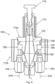
- control element 170 that controls the size of the gap 122 between the inner and outer bodies 130, 110. It does this by moving the inner and outer bodies 130, 110 along the longitudinal axis L, i.e., in this embodiment up and down, at different rates in dependence on a given user input.
- the user input is rotation of the control element that is effected by a user.
- control element 170 preferably takes the form of a differential screw, although other forms of the control element 170 are possible.
- the control element 170 extends along longitudinal axis L and defines an elongate body.
- the control element 170 has a first portion 174 for engaging the outer body 110 and a second portion 176 for engaging the inner body 130.
- the second portion 176 is arranged below the first portion 174 within the compensator 100.
- the first portion 174 has a greater diameter than the second portion 176, and a narrowed neck region 177 is defined between the first and second portions 174, 176, which acts as a thread relief and facilitates manufacture of the element 170.
- the first portion 174 and second portion 176 of the control element 170 define screw-thread surfaces for engagement with the outer and inner bodies 110, 130 respectfully.
- the outer and inner bodies 110, 130 define corresponding first and second openings that receive the control element, with the openings having corresponding screw-thread surfaces respectively to facilitate this engagement.
- the first opening of the outer body 110 is defined in a first cavity 114 at the top of the outer body 110, while the second opening of the inner body 130 is defined in a second cavity 134 at the top of the inner body 130.
- the control element 170 extends through the first and second cavities 114, 134 in this way.
- first part 178 of the first portion 174 is arranged within the outer body 110 where it engages with the outer body 110
- a second part 179 of the first portion 174 (i.e., above the first part 178) can be arranged outside the outer body 110 for engagement by a user.
- the second part 179 of the first portion 174 may define an engagement portion 172, for example in the form of a grip, for engagement/ rotation by a user.
- the second portion 176 of the control element 170 is wholly arranged within the inner and outer bodies 130, 110.
- the inner body 130 is non-rotational with respect to the outer body 110, i.e., it does not rotate along with the rotation of the control element 170. This can be achieved by way of rotation stop that rotationally fixes the inner body 130 relative to the outer body 110: for example, via a grub screw 190 connecting the inner and outer bodies 130, 110, best seen in Figure 2 . In these ways, the inner body 130 can be prevented from rotating with the outer body 110, thereby facilitating relative movement of the inner and outer bodies 130, 110.
- the first portion 174 of the differential screw control element 170 has a smaller thread pitch than the second portion 176.
- This difference in thread pitch means that rotation of the control element 170 brings about a greater relative movement between the control element 170 and the inner body 130 than between the control element 170 and the outer body 110.
- the first portion 174 preferably has a thread pitch of between 0.65 and 0.85mm, and more preferably 0.75mm
- the second portion 176 preferably has a thread pitch of between 0.9mm and 1.1mm, and more preferably 1.0mm.
- the first portion 174 of the differential screw control element 170 has a larger thread pitch than the second portion 176. This means that the differential screw control element 170 is to be rotated anti-clockwise to move the inner and outer bodies 130, 110 closer together.
- the first portion 174 preferably has a thread pitch of between 0.9mm and 1.1mm, and more preferably 1.0mm, while between the second portion 176 has a thread pitch of between 0.65 and 0.85mm, and more preferably 0.75mm.
- the control element 170 is configured such that one full rotation of the control element 170 causes a relative longitudinal displacement between the inner and outer bodies 130, 110 of between 0.20mm and 0.30mm.
- the change in the gap 122 i.e., the perpendicular gap between the inner and outer bodies 130, 110
- the change in the gap 122 is of a lower magnitude than the magnitude of the lateral movement.
- the outer surface of the inner body 130 and the inner surface of the outer body 110 are angled with respect with respect to the L axis (to the same degree).
- This relative longitudinal displacement between the inner and outer bodies 130, 110 therefore provides only a change in a few microns in the perpendicular gap 122 between the inner body 130 and the outer body 110, providing particularly fine control of the gap size.
- the screw threads may have other properties that differ.
- the screw threads may be of different diameters.
- the screw thread of the first portion 174 has an ISO Metric thread dimension M8 and the screw thread of the second portion 176 has an ISO Metric thread dimension M6.
- a locknut may be used.
- a stopping device may be applied to the screw to hold the screw in place and prevent it from rotating except for when the screw is being manually adjusted by a user.
- Such a device may be preferable over a locknut because access to the screw is limited and so using a locknut can be challenging.
- the stopping device takes the form of a "clicker" comprising three sprung plastic clips that are applied to the top of the screw 170 and hold it in place.
- the compensator 100 is preferably provided with a cooling circuit 160 arranged within the outer body 110 to cool the compensator 100, as shown in Figure 6 .
- Chilled soda is perpetually circulated through the cooling conduit 160 to keep the outer body 110 and compensator 100 at a constant temperature, which is preferably at or close to 0 °C, and to prevent stagnation of the soda within the carbonated beverage dispenser 1.
- the cooling further helps to reduce outgassing in the dispensed carbonated beverage.
- the constant temperature helps to ensure a constant liquid viscosity of the dispensed soda, and hence a constant flow rate. This is important to ensure that the liquid dispense volume is consistent with every dispense.
- a cooling circuit separate to the compensator 100 can be used.
- the cooling circuit 100 comprises a cooling inlet 162, a cooling outlet 164, and a cooling conduit 166 extending between the cooling inlet 162 and the cooling outlet 164.
- the cooling conduit 166 takes the form a channel that extends at least partially around the compensator chamber 120 through the outer body 110. In use, as shown in Figure 6 , soda enters through the cooling inlet 162, then passes around the cooling conduit 166, and then exits out the cooling outlet 164.
- the outer body 110 is made up of upper and lower outer bodies 110a, 110b. These are preferably shaped such that when the upper outer body 110a is arranged on top of the lower outer body 110b in use, the two define the cooling conduit 166 therebetween. This arrangement is easily manufactured since it would not be easy to access the inside of the outer body 110 to machining the cooling conduit 166 if they were formed as one.
- the cooling inlet 162 and the cooling outlet 164 are connected to the cooling circuit from underneath the lower outer body 110b.
- the cooling inlet 162 and the cooling outlet 164 are preferably removably attachable to the lower outer body 110b and hence are removably connectable to the cooling conduit 166.
- the cooling inlet 162 and the cooling outlet 164 screw into the lower outer body 110b. This positioning of the cooling inlet and cooling outlet underneath advantageously minimises the overall space envelope of the compensator 100,
- Each of the upper outer body 110a and lower outer body 110b define a flat meeting surface which contact each other and are flush with each other when the upper outer body 110a is arranged on top of lower outer body 110b. Furthermore, each of the upper outer body 110a and lower outer bodies 110b are made of a thermally conducive metal such as steel, although plastics may also be used. This flush arrangement and the material of the outer body 110 both facilitate the cooling effect of the cooling circuit 160 through the compensator 100.
- the upper outer body 110a and lower outer body 110b are held together by a fixing means such as screws. Without said fixing means, the high pressures of the soda passing through the compensator 100 could force the upper outer body 110a and lower outer body 110b apart.
- the soda delivery system 200 delivers cooled and carbonated soda to the compensator 100 both for cooling of the compensator 100 and for flow regulation by the compensator 100 for dispensing.
- the soda delivery system 200 comprises a chiller-carbonator 220 for chilling and carbonating soda.
- the chiller-carbonator 220 maintains all the soda at the right temperature and carbonation both for cooling of the compensator via the cooling circuit 160, and also for dispensing and consumption.
- the soda delivery system 200 comprises a first soda delivery conduit 230, a second soda delivery conduit 232, a third soda delivery conduit 234, a fourth soda delivery conduit 236, and a controller valve 240. Any suitable components may be used for these purposes.
- the first soda delivery conduit 230 couples the chiller-carbonator 220 to the controller valve 240 and is for transporting cooled and carbonated soda water from the chiller-carbonator 220 to the controller valve 240.
- the second delivery conduit 232 couples the controller valve 240 to the cooling inlet 162 and is for transporting cooled soda water from the controller valve 240 to the cooling inlet 162, for passage through the cooling conduit 166 and hence for cooling the compensator 100.
- the third soda delivery conduit 234 couples the cooling outlet 164 to the chiller-carbonator 220 and is for transporting compensator-warmed soda that has passed through the cooling conduit 166 from the cooling outlet 164 to the chiller-carbonator 220 for re-cooling (and re-carbonation) thereby.
- the fourth soda delivery conduit 236 couples the controller valve 240 to the inlet 140 of the compensator 100 and is for transporting cooled and carbonated soda water from the controller valve 240 to the inlet 140 of the compensator 100 for flow regulation by the compensator 100 and then dispensing.
- the controller valve 240 is configurable in a first configuration and a second configuration.
- the controller valve 240 directs soda water from the first soda delivery conduit 230 to the second delivery conduit 232 for circulation around the cooling circuit 160 and back towards the chiller-carbonator 220 for re-cooling and re-carbonation.
- soda is still directed around the cooling circuit, and the controller valve 240 additionally directs soda water from the first soda delivery conduit 230 to the inlet 140 of the compensator 100 for flow regulation by the compensator 100 and then dispensing.
- the controller valve 240 is arranged in the first configuration unless configured otherwise by the controller. When operated on by the controller, the controller valve 240 is arranged in the second configuration. In this way, soda is usually circulating the cooling circuit 160 to maintain coolness of the compensator 100 and also to prevent stagnation of the soda within the compensator 100, thereby keeping the carbonated beverage dispenser 1 ready for use. When operated on by the controller, for example because a user has provided a 'dispense' input, soda is then also directed to the inlet 140 of the compensator 100 for flow regulation by the compensator 100 and then dispensing.
- the chiller-carbonator is preferably configured to pressurise the soda to between 80 and 100 PSI, and preferably 90 PSI, i.e., between 5.5 bar and 6.9 bar, and preferably 6.2 bar. This provides a sufficient level of carbonation in the dispensed carbonated beverage for high quality carbonated beverages. This differs from the typical pressure of a soda gun, which is typically less than 60 PSI (4,14 bar).
- the mixing chamber 300 will now be described in more detail, with reference Figures 1 , 8a , 8b and 9 .
- the mixing chamber 300 extends in a perpendicular axis P away from the outlet 150 of the compensator 100.
- the mixing chamber 300 defines a body that is substantially cuboid in shape, and in this example is elongate along the perpendicular axis P.
- the body of the mixing chamber 300 has lower and upper walls 310, 320, front and back walls 330, 340 and first and second side walls 350, 360.
- the first and second side walls 350, 360 are longer than the front and back walls 330, 340.
- the mixing chamber defines a cavity 301 therein, which receives and mixes carbonated water from the compensator 100, and additives from the additive dispensing system 400.
- the cavity 301 has first, second and third distinct openings 305, 370, 375 defined therein.
- the first opening 305 extends across a length of the upper wall 320 of the mixing chamber 300 such that the mixing chamber 300 takes the form of a trough, being open at its top.
- the additive dispensing system 400 dispenses at least one additive into the mixing chamber 300 through the first opening 305.
- the volume defined by the mixing chamber 300 is sufficient such that liquids of the mixing chamber 300 do not overflow through the first opening 305.
- the second opening 370 is defined in the back wall 340 for receiving soda from the outlet 150 of the compensator 100
- the third opening 375 is defined in the front wall 330 for delivering soda drink out of the mixing chamber 300.
- the second and third openings 370, 375 are therefore located on opposite ends of the mixing chamber 300.
- a base surface 312 that defines a base of the cavity 301.
- the base surface 312 slopes downwardly moving from the second opening 370 to the third opening 375, thereby encouraging a flow of liquid towards the third opening.
- the mixing chamber 300 is preferably removable from the compensator 100 of the carbonated beverage dispenser 1. This allows the mixing chamber 300 to be cleaned with ease. It is particularly beneficial that the mixing chamber 300 is easily cleanable, because the mixing chamber is in contact with the soda drink mixture (i.e., the mixture of carbonated water and syrup), which typically provides an environment in which mould can grow and is therefore particularly in need of regular cleaning.
- the soda drink mixture i.e., the mixture of carbonated water and syrup
- the compensator 100 comprises a first connection part 158 defined by the second outlet channel 154 of the outlet 150
- the mixing chamber 300 comprises a second connection part 380 extending from the back wall and around the second opening.
- the second connection part 380 is male, i.e., comprises a projection in the form of a collar 382
- the first connection part 158 is female, i.e., comprises a receptacle in the form of a socket 159, although alternative arrangements are foreseen too.
- the two connection parts 158, 380 are configured such that they are connectable with a frictional fit. This therefore ensure a firm coupling of the mixing chamber 300 to the compensator 100, where the coupling can be quickly and easily connected and disconnected.
- an O-ring 386 is used to enhance the frictional fit.
- the collar 382 of the second connection part comprises a circumferential channel 384 in its outer surface that houses an O-ring 386.
- the O-ring 386 provides a tight sealing contact against an internal surface of the collar 382 to hold the mixing chamber 300 in place.
- connection between the mixing chamber 300 and the compensator arrangement 100 is also magnetised: to this end, one or more first magnetic elements may be housed in or adjacent to the collar 382 and/or socket 159.
- the magnetisation provides a particularly secure fit and can also guide the collar 382 into the socket 159, to assist the user in fitting the mixing chamber in place.
- the magnetic connection can also be combined with a sensor to detect whether the mixing chamber is in place, and thus can be used as a 'switch'.
- the sensor can take the form of one or more second magnetic elements that are also housed in or adjacent to the collar 382 and/or socket 159 and which sense when a magnetic connection has not been made.
- the first and second magnetic element(s) are the same, in others they are separate.
- the sensor may be a touch sensor or any other suitable type of sensor.
- the control unit will not permit the unit to dispense any liquid when the mixing chamber is detected to be not in place, thereby avoiding accidental use of the unit without the mixing chamber being in place.
- the mixing chamber 300 and the compensator arrangement 100 can be attached by way of a rubber seal.
- a mechanical (instead of magnetic) switch can be provided on the compensator 100.
- the control unit will not permit the compensator 100 to dispense any liquid unless the mechanical switch is operated by the user (i.e., to indicate that the mixing chamber 300 is correctly arranged in place with respect to the compensator 100).
- the mixing chamber 300 is preferably thermally coupled to the outer body 110 of the compensator 100 when attached thereto. In this way, the cooling of the compensator 100 can be used to cool the mixing chamber 300 too, thus reducing the likelihood of outgassing.
- the mixing chamber 300 may be made of a thermally conducive metal such as steel, although plastics may also be used. Plastic may be preferred because it results in a simplified manufacturing process and reduced costs - all plastic parts may be moulded separately and then welded together. Also, plastic has been found to ensure sufficient heat transfer, and it can be easier to achieve a much smoother finish on plastic parts than on metal counterparts.
- the mixing chamber 300 is made of material such that it is also dishwasher safe, since this is the part that is to be cleaned.
- the additive dispensing system 400 will now be described, with further reference to Figure 1 .
- the additive dispensing system 400 comprises at least one additive dispenser 410 preferably in the form of at least one dispensing nozzle extending vertically downward.
- the additive dispensing system 400 further comprises at least one additive store 420 for storing the additive(s), and at least one additive delivery conduit 430 for transporting additive from the additive store(s) 432 to the respective additive dispenser 410 for dispensing.
- the at least one additive dispenser 410 is arranged above the first opening 305 of the mixing chamber 300 such that the spacing S is defined therebetween. In this way, the additive dispenser 410 never touches the liquids in mixing chamber 300, and so will never be contaminated thereby. Hence, the additive dispensers 410 do not need to be cleaned as frequently as the mixing chamber.
- the additive dispensing system 400 comprises a plurality of additive dispensers 410 each arranged to dispense an additive into the mixing chamber 300 through the first opening 305, a plurality of additive stores 420 for storing each additive, and a plurality of additive delivery conduits 430 for transporting additive from each additive store 432 to the respective additive dispenser 410 for dispensing.
- This configuration is preferable as it avoids contamination of additives, and hence reduces the need for cleaning.
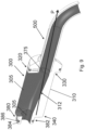
- the carbonated beverage outlet 500 takes the form of a circular spout that extends away from the third opening of the mixing chamber 300 along the perpendicular axis P, and curves downwards towards its end.
- the carbonated beverage outlet 500 is preferably fixedly connected to the front wall 330 of the mixing chamber 300 such that both the mixing chamber 300 and the carbonated beverage outlet 500 are removable from the carbonated beverage dispenser 1.
- the two components 300, 500 can instead be integrally formed. This allows the carbonated beverage outlet 500 to be cleaned with ease along with the mixing chamber 300.
- the carbonated beverage outlet 500 is preferably thermally coupled to the mixing chamber 300 and the outer body 110 of the compensator 100. In this way, the cooling of the compensator 100 can be used to cool the carbonated beverage outlet 500 too, thus reducing the likelihood of outgassing in the dispensed carbonated beverage.
- the carbonated beverage outlet 500 may be made of a thermally conducive metal such as steel, although other materials such as other metals, or plastics may also be used too. Plastic may be preferred because it results in a simplified manufacturing process and reduced costs - all plastic parts may be moulded separately and then welded together. Also, plastic has been found to ensure sufficient heat transfer, and it can be easier to achieve a much smoother finish on plastic parts than on metal counterparts.
- the carbonated beverage outlet 500 is made of material that is fully dishwasher safe, since it is to be cleaned regularly.
- the outer surface of the inner body 130, an inner surface of the inlet 140, an inner surface of the outlet 150, an inner surface of the mixing chamber 300, and an inner surface of the carbonated beverage outlet 500 all preferably have a surface roughness of no more than 0.1 microns Ra. This smoothness reduces nucleation sites for bubble formation, hence reducing outgassing in the dispensed mixed soda. By ensuring that these surfaces in particular have a high degree of smoothness, outgassing can be minimised.
- control unit (not shown) of the carbonated beverage dispenser 1 will be described.
- the control unit provides electrical control of the carbonated beverage dispenser 1.
- the carbonated beverage dispenser 1 is also provided with a user input interface electrically coupled to the control unit.
- a user can input a selection of variables, including for example which carbonated beverage to dispense, and what volume of such beverage.
- the control unit controls the operation of a control valve in the or each additive dispenser 410 to produce a particular carbonated beverage, and to dispense a particular volume.
- the control unit controls dispense of the carbonated water and the additive into the mixing chamber 300 separately.
- the control unit is configured to stop the additive being dispensed from additive dispensing system 400 a short time before it stops soda being dispensed the compensator 100. This means that at the end of any dispense cycle, the final liquid present in the mixing chamber 300 is only carbonated water, rather than the soda drink mixture. This final amount of carbonated water acts to clean the mixing chamber 300 at the end of every dispense cycle, to prevent flavour cross-over with the next soda drink being prepared, and to keep the mixing chamber 300 as clean as possible during use of the unit.
- the inlet 140 of the compensator 100 may be provided with the controller valve 240 to control whether soda is delivered to the compensator 100, and hence to the mixing chamber 300.
- a control valve (not shown) in the or each additive dispenser 410 controls whether additive is delivered to the mixing chamber 300.
- the control unit is electrically coupled to each of the controller valve 240 and/ or the or each additive dispenser valve 410, to control dispense of the carbonated water and the additives.
- the same control unit may also be configured to detect the magnetic interlock 390 between the mixing chamber 300 and the compensator 100, and to prevent the dispense of liquids if the mixing chamber 300 is disconnected, as has already been described.
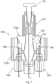
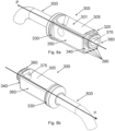
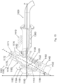
- Figures 10 and 11 show an alternative embodiment of the carbonated beverage dispenser 1001, This embodiment is the same as the above embodiment, except that (1) the compensator 1100 of the carbonated beverage dispenser 1001 is arranged at a different, non-vertical orientation, (2) the control element 1170 has a different configuration, (3) the cooling circuit 1160 has a different configuration, and (4) at least one additive dispenser 1410 is arranged at a different, non-vertical orientation, as will be described below.
- the compensator 1100 of the carbonated beverage dispenser 1001 is arranged at a different, non-vertical orientation
- the control element 1170 has a different configuration
- the cooling circuit 1160 has a different configuration
- at least one additive dispenser 1410 is arranged at a different, non-vertical orientation
- the longitudinal axis L, along which the compensator 1100, and the inner and outer bodies 1130, 1110 extend, is not arranged vertically but is instead arranged to extend upwardly and at angle ⁇ with respect to the vertical.
- compensator 1100 is arranged/ tilted/ slanted at angle ⁇ with respect to the vertical direction.
- Angle ⁇ is preferably between around 20 and 85°, more preferably between around 40 and 80°, more preferably between around 50 and 70°, more preferably around 55 and 65°, and more preferably around 60°.
- the first region or upstream region 1180 of the compensator body 1130 is a lower region 1180 and the second region or downstream region 1182 of the compensatory body 1130 is an upper region 1182.
- the inlet 1140 opens into the first region 1180 and the outlet 1150 opens into the second region 1182: in this way, the inlet 1140 is arranged below the outlet 1150, so that soda therefore travels upwards (instead of downwards) through the gap 1122 defined between the inlet 1140 and outlet 1150.
- the pressure differential across the compensator 1120 provides this movement of soda therethrough.
- the outlet 1150 of the compensator 1100 is not L shaped and instead only extends in one direction, namely along perpendicular axis P.
- the outlet 1150 of the compensator 1100 extends out the side of the second region 1182 of the compensator chamber 1120.
- one end of the outlet 1150 is fluidly connected to the second region 1182 of the compensator chamber 1120 and receives regulated soda therefrom.
- the other end of the outlet 1150 is fluidly connected to the mixing chamber 1300 and delivers regulated soda therein.
- the mixing chamber 1300 and the carbonated beverage outlet 1500 both extend along perpendicular axis P away from the outlet 1150 of the compensator 1100.
- the inlet 1140 remains L shaped in this embodiment, but in this embodiment the inlet 1140 delivers fluid into the first region 1180 of the compensator chamber 1120 along longitudinal axis L.
- the first inlet channel 1142 extends upwards at an angle perpendicular to longitudinal axis L, while the second inlet channel 1144 extends upwards along longitudinal axis L through the outer body 1110 of the compensator 1100 and into the compensator chamber 1120. In this way, the configuration of the inlet 1140 is tilted/ slanted compared to the first embodiment.
- the shape of the inner and outer bodies 1130, 1110 is the same, but inverted.
- the diameter of the inner body 1130 and the diameter of the compensator chamber 1120 are preferably approximately constant when moving upwardly along the longitudinal axis L.
- the diameter of the inner body 1130 and the diameter of the compensator chamber 1120 increase at substantially the same fixed rate when moving upwards along the longitudinal axis L.
- the diameter of the inner body 1130 and of the compensator chamber 1120 decrease at different fixed rates when moving upwards along the longitudinal axis L.
- the angle defined between the outer surface of the inner body 1130 and longitudinal axis L is slightly less than the angle defined between the inner surface of the outer body 1110 and longitudinal axis L at each point along the longitudinal axis L in the upper region 1182 of the compensator 1100, so the gap 1122 between the inner and outer bodies 1130, 1110 increases moving up along longitudinal axis L in the upper region 1182.
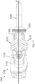
- control element 1170 is arranged at a downstream end of the compensator 1100, i.e., downstream of the second region 1182 of the compensator body 1100.
- the control element 1170 takes the form of a differential screw in the manner described above but has a different configuration.
- the control element 1170 comprises a collar 1171 having an outer surface 1174 and an inner surface 1176.
- the outer surface 1174 defines a first portion that is configured to engage with the outer body 1110 of the compensator assembly 1100
- the inner surface 176 defines a second portion that is configured to engage with the inner body 1130 of the compensator 1100.
- the collar 1171 is located between the inner and outer bodies 1130, 1110 of the compensator 1100.
- the differential screw of the control element 1170 operates in substantially the same way described above.
- the outer surface 1174 is provided with a first thread and the inner surface 1176 is provided with a second thread, with the first and second threads each having a different pitch.
- the outer body 1110 and inner body 1130 are each provided with corresponding threads. Due to the different pitches, rotation of the control element 1170 causes the inner and outer bodies 1110, 1130 to move along the longitudinal axis L by different amounts, causing relative displacement between the inner and outer bodies 1110, 1130, thereby adjusting the size of the gap 1122 between the bodies 1110, 1130 in the manner already described above.
- Other features of the control element 1170, such as the sizes and pitch of the screw thread may be the same as the embodiment above.
- the control element 1170 may also be provided with an engagement portion 1172 that protrudes out of the outer body 1130 to facilitate engagement by a user.
- the engagement portion 1172 may be an end region of the collar 1171.
- the above-described tilted arrangement of the compensator 1100 and collar arrangement of the control element are advantageous because they provide a particularly compact and simple arrangement of the compensator system.
- the cooling circuit 1160 also has a different configuration in Figure 10 compared to Figure 1 .
- the cooling inlet 1162 still extends into the outer body 1110 through the base of the outer body 1110; however, instead of exiting through the base of the outer body 1110, the cooling outlet 1164 exits the outer body 1110 through the top of the outer body 1110. Locating the outlet 1164 at the top (as opposed to at the bottom) of the outer body 1110 is advantageous since it reduces the incidence of bubbles getting trapped in the cooling circuit 1160.
- the additive dispenser 1410 still takes the form of one or more dispensing nozzles.
- the or each nozzle is tilted at an angle with respect to the vertical such that it dispenses an additive into the mixing chamber 1300 along the direction of flow through the mixing chamber 1300, i.e., along axis P.
- each dispensing nozzle may be tilted with respect to angle P such that it dispenses an additive inwardly (i.e., laterally) into the mixing chamber 1300 from outside of the mixing chamber 1300 from either side of the mixing chamber 1300 about axis P.
- the dispensing nozzles may be split into a first plurality or bundle of dispensing nozzles for dispensing "base” syrups and a second plurality of bundle of dispensing nozzles for dispensing "flavour liquids".
- the first bundle may be tilted in one or two of the directions mentioned above, while the second bundle may be arranged to extend directly down along the vertical. Only the nozzles that dispense "base” syrups are angled in the direction of flow in this embodiment because the flow rate of these syrups is larger than of the flavour liquids.
Landscapes
- Devices For Dispensing Beverages (AREA)
Claims (14)
- Ausgabevorrichtung (1) für kohlensäurehaltige Getränke, zum Ausgeben eines kohlensäurehaltigen Getränks, das Sprudel und mindestens einen Zusatzstoff umfasst, wobei die Ausgabevorrichtung (1) für kohlensäurehaltige Getränke einen Kompensator (100) zum Regeln des Volumenstroms von Sprudel umfasst, wobei der Kompensator (100) Folgendes umfasst:einen äußeren Körper (110), der eine Kompensatorkammer (120) definiert,einen Einlass (140) zum Zuführen von Sprudel in die Kompensatorkammer (120) und einen Auslass (150) zum Zuführen von Sprudel aus der Kompensatorkammer (120) heraus,einen inneren Körper (130), der innerhalb der Kompensatorkammer (120) und zwischen dem Einlass (140) und dem Auslass (150) angeordnet ist, wobei ein Spalt (122) zwischen dem inneren Körper (130) und dem äußeren Körper (110) definiert ist, um den Volumenstrom von zwischen dem Einlass (140) und dem Auslass (150) hindurchgelangenden Sprudel zu regeln, undein Steuerelement (170), das dazu konfiguriert ist, eine Benutzereingabe von einem Benutzer zu empfangen und die Größe des Spalts (122) in Abhängigkeit von der Benutzereingabe zu steuern, wobei für eine gegebene Benutzereingabe das Steuerelement (170) den inneren Körper (130) relativ zu dem Steuerelement (170) um ein erstes Maß und den äußeren Körper (110) relativ zu dem Steuerelement (170) um ein zweites Maß bewegt, wobei das erste Maß nicht gleich dem zweiten Maß ist.
- Ausgabevorrichtung für kohlensäurehaltige Getränke nach Anspruch 1, wobei das Steuerelement (170) drehbar ist und wobei die Benutzereingabe eine Drehung des Steuerelements ist.
- Ausgabevorrichtung für kohlensäurehaltige Getränke nach Anspruch 1 oder Anspruch 2, wobei das Steuerelement (170) die Form einer Differentialschraube einnimmt, die einen ein erstes Gewinde zum Eingriff mit dem äußeren Körper (110) umfassenden ersten Abschnitt (174) und einen ein zweites Gewinde zum Eingriff mit dem inneren Körper (130) umfassenden zweiten Abschnitt (176) aufweist, wobei das erste Gewinde eine andere Gewindesteigung aufweist als das zweite Gewinde.
- Ausgabevorrichtung für kohlensäurehaltige Getränke nach Anspruch 3, wobei das erste Gewinde eine Steigung von zwischen 0,65 und 0,85 mm aufweist und wobei das zweite Gewinde eine Steigung von zwischen 0,9 mm und 1,1 mm aufweist.
- Ausgabevorrichtung für kohlensäurehaltige Getränke nach einem der vorangehenden Ansprüche, abhängig durch Anspruch 2, wobei für eine volle Umdrehung des Steuerelements (170) das Steuerelement eine relative Längsverschiebung zwischen dem inneren und dem äußeren Körper (130, 110) von zwischen 0,20 mm und 0,30 mm bewirkt.
- Ausgabevorrichtung für kohlensäurehaltige Getränke nach einem der vorangehenden Ansprüche, wobei der innere Körper (130) in Bezug auf den äußeren Körper (110) drehfest ist.
- Ausgabevorrichtung für kohlensäurehaltige Getränke nach einem der vorangehenden Ansprüche, wobei das Steuerelement (170) einen Eingriffsabschnitt (172) umfasst, der aus dem äußeren Körper (110) herausragt, um ein Eingriffsmerkmal zum Ineingriffnehmen durch einen Benutzer zu definieren.
- Ausgabevorrichtung für kohlensäurehaltige Getränke nach einem der vorangehenden Ansprüche, wobei der Kompensator (100) einen ersten Bereich (180) nahe dem Einlass (140), einen zweiten Bereich (182) nahe dem Auslass (150) und einen mittleren Bereich (181) dazwischen umfasst, wobei optional in dem ersten Bereich (180) ein Durchmesser des inneren Körpers (130) und ein Durchmesser der Kompensatorkammer (120) zwischen dem Einlass (140) und dem mittleren Bereich (181) ungefähr konstant sind.
- Ausgabevorrichtung für kohlenstoffhaltige Getränke nach Anspruch 8, wobei in dem mittleren Bereich (181) der oder ein Durchmesser des inneren Körpers (130) und der oder ein Durchmesser der Kompensatorkammer (120) mit im Wesentlichen der gleichen festen Rate zwischen dem ersten und dem zweiten Bereich (180, 182) zunehmen.
- Ausgabevorrichtung für kohlensäurehaltige Getränke nach einem von Anspruch 8 oder Anspruch 9, wobei in dem zweiten Bereich (182) der oder ein Durchmesser des inneren Körpers (140) und der Kompensatorkammer (120) mit unterschiedlichen festen Raten zwischen dem mittleren Bereich (181) und dem Auslass (150) abnehmen.
- Ausgabevorrichtung für kohlensäurehaltige Getränke nach einem der vorangehenden Ansprüche, wobei die Ausgabevorrichtung für kohlensäurehaltige Getränke ferner Folgendes umfasst: ein Sprudelzuführsystem (200), umfassend einen Kühler-Karbonisierer (220) zum Kühlen und Karbonisieren von Sprudel für den Kompensator (100); eine innerhalb des äußeren Körpers angeordnete Kühlleitung (166), wobei die Kühlleitung (166) dazu konfiguriert ist, eine Kühlflüssigkeit aufzunehmen; eine erste Sprudelzuführleitung (230) zum Fördern von Sprudel von dem Kühler-Karbonisierer (220) zu der Kühlleitung (166) zum Kühlen des Kompensators (100); und eine zweite Sprudelzuführleitung (232) zum Fördern von Sprudel von dem Kühler-Karbonisierer (220) zu dem Kompensator (100) zur Stromregelung, wenn selektiv von einem Benutzer betätigt.
- Ausgabevorrichtung für kohlensäurehaltige Getränke nach Anspruch 11, wobei der Kühler-Karbonisierer (200) dazu konfiguriert ist, Sprudel auf zwischen 5,5 bar und 6,9 bar und vorzugsweise 6,2 bar mit Druck zu beaufschlagen.
- Ausgabevorrichtung für kohlensäurehaltige Getränke nach einem der vorangehenden Ansprüche, wobei die Ausgabevorrichtung für kohlenstoffhaltige Getränke ferner Folgendes umfasst: ein Zusatzstoffausgabesystem (400) zum Ausgeben mindestens eines Zusatzstoffs und eine Mischkammer (300) zum Aufnehmen von Sprudel von dem Kompensator (100) und mindestens einem Zusatzstoff von dem Zusatzstoffausgabesystem (400) und Mischen des Sprudels mit mindestens einem Zusatzstoff, um ein auf Sprudel basierendes Getränk zu bilden.
- Verfahren zum Ausgeben eines kohlenstoffhaltigen Getränks unter Verwendung der Getränkeausgabevorrichtung nach Anspruch 13, wenn abhängig von Anspruch 12, wobei das Verfahren Folgendes umfasst:Beaufschlagen des Sprudels mit Druck auf einen Druck zwischen 5,5 bar und 6,9 bar,Leiten des druckbeaufschlagten Sprudels durch den Kompensator der Getränkeausgabevorrichtung in die Mischkammer;Ausgeben mindestens eines Zusatzstoffs in die Mischkammer; undErmöglichen, dass sich das Sprudel und der Zusatzstoff in der Mischkammer mischen, um ein auf Sprudel basierendes Getränk zu bilden.
Applications Claiming Priority (2)
| Application Number | Priority Date | Filing Date | Title |
|---|---|---|---|
| GB2208241.6A GB2619505B (en) | 2022-06-06 | 2022-06-06 | Carbonated beverage dispenser |
| PCT/EP2023/065149 WO2023237566A1 (en) | 2022-06-06 | 2023-06-06 | Carbonated beverage dispenser |
Publications (3)
| Publication Number | Publication Date |
|---|---|
| EP4452823A1 EP4452823A1 (de) | 2024-10-30 |
| EP4452823B1 true EP4452823B1 (de) | 2025-01-15 |
| EP4452823C0 EP4452823C0 (de) | 2025-01-15 |
Family
ID=82404668
Family Applications (1)
| Application Number | Title | Priority Date | Filing Date |
|---|---|---|---|
| EP23734897.4A Active EP4452823B1 (de) | 2022-06-06 | 2023-06-06 | Ausgabevorrichtung für kohlensäurehaltige getränke |
Country Status (7)
| Country | Link |
|---|---|
| US (1) | US20230391605A1 (de) |
| EP (1) | EP4452823B1 (de) |
| JP (1) | JP7787327B2 (de) |
| AU (1) | AU2023282359B2 (de) |
| ES (1) | ES3014280T3 (de) |
| GB (2) | GB2619505B (de) |
| WO (1) | WO2023237566A1 (de) |
Families Citing this family (1)
| Publication number | Priority date | Publication date | Assignee | Title |
|---|---|---|---|---|
| GB2640360A (en) * | 2024-07-02 | 2025-10-15 | Diageo Great Britain Ltd | Nozzle for a dispenser |
Family Cites Families (7)
| Publication number | Priority date | Publication date | Assignee | Title |
|---|---|---|---|---|
| JPS5567000U (de) * | 1978-10-30 | 1980-05-08 | ||
| GB2117094A (en) * | 1982-03-22 | 1983-10-05 | British Syphon Ind Ltd | Flow restrictor for beer line |
| NZ292867A (en) * | 1994-09-23 | 1999-03-29 | Vassingerod Metalstoberi As | Tapping faucet for use with beer keg |
| US6896159B2 (en) * | 2000-06-08 | 2005-05-24 | Beverage Works, Inc. | Beverage dispensing apparatus having fluid director |
| JP5009153B2 (ja) * | 2005-12-02 | 2012-08-22 | シーケーディ株式会社 | 流量調整弁 |
| DE102014105554A1 (de) * | 2014-04-17 | 2015-10-22 | Cmb Schankanlagen Gmbh | Kompensatorzapfhahn |
| EP3315458A1 (de) * | 2016-10-28 | 2018-05-02 | Anheuser-Busch InBev S.A. | Ausgabevorrichtung zur steuerung der schaumbildung bei der ausgabe eines malzbasierten fermentierten getränks (mbfb), das durch mischen eines mbfb-konzentrats mit einem kohlensäurehaltigen verdünnungsmittel in-situ hergestellt wird |
-
2022
- 2022-06-06 GB GB2208241.6A patent/GB2619505B/en active Active
-
2023
- 2023-06-05 US US18/205,904 patent/US20230391605A1/en active Pending
- 2023-06-06 EP EP23734897.4A patent/EP4452823B1/de active Active
- 2023-06-06 AU AU2023282359A patent/AU2023282359B2/en active Active
- 2023-06-06 WO PCT/EP2023/065149 patent/WO2023237566A1/en not_active Ceased
- 2023-06-06 GB GB2411293.0A patent/GB2629546B/en active Active
- 2023-06-06 ES ES23734897T patent/ES3014280T3/es active Active
- 2023-06-06 JP JP2024553345A patent/JP7787327B2/ja active Active
Also Published As
| Publication number | Publication date |
|---|---|
| AU2023282359A1 (en) | 2024-08-22 |
| AU2023282359B2 (en) | 2025-08-14 |
| GB2629546A (en) | 2024-10-30 |
| ES3014280T3 (en) | 2025-04-21 |
| GB2619505B (en) | 2024-06-05 |
| JP2025508047A (ja) | 2025-03-21 |
| US20230391605A1 (en) | 2023-12-07 |
| GB202411293D0 (en) | 2024-09-11 |
| JP7787327B2 (ja) | 2025-12-16 |
| GB202208241D0 (en) | 2022-07-20 |
| EP4452823A1 (de) | 2024-10-30 |
| EP4452823C0 (de) | 2025-01-15 |
| GB2619505A (en) | 2023-12-13 |
| GB2629546B (en) | 2025-09-03 |
| WO2023237566A1 (en) | 2023-12-14 |
Similar Documents
| Publication | Publication Date | Title |
|---|---|---|
| EP0159399B1 (de) | Abgabevorrichtung für Flüssigkeiten | |
| US4523697A (en) | Liquid dispensing package | |
| US7278454B2 (en) | Beverage dispensing apparatus | |
| US4408701A (en) | Liquid dispensing valve | |
| US8997803B2 (en) | Dispensing system and method of controlling the system | |
| CN102762486B (zh) | 具有水冷却器和浓缩物添加装置的饮料分配器 | |
| US9950917B2 (en) | Beverage preservation and dispensing device | |
| EP4452823B1 (de) | Ausgabevorrichtung für kohlensäurehaltige getränke | |
| AU2005266136B2 (en) | Beverage dispensing tap with spouts for the liquid and the foam | |
| GB2357751A (en) | Dispenser with flow regulator | |
| US20060032869A1 (en) | Beverage dispensing apparatus | |
| US20160340081A1 (en) | Container with laminar flow | |
| JPS62106827A (ja) | 後混合清涼飲料混合装置 | |
| EP0222596B1 (de) | Vorrichtung zum Mischen von Fruchtkonzentraten und nichtschäumendem Wasser | |
| US20250353726A1 (en) | Beverage mixing and dispensing system and tap for use therein | |
| GB2313824A (en) | Dispensing beverages | |
| HK40034380A (en) | Methods and apparatus for post-mix drink dispensing | |
| HK1109131A (en) | Beverage dispensing apparatus | |
| HK1084653B (en) | Beverage dispensing apparatus |
Legal Events
| Date | Code | Title | Description |
|---|---|---|---|
| STAA | Information on the status of an ep patent application or granted ep patent |
Free format text: STATUS: UNKNOWN |
|
| STAA | Information on the status of an ep patent application or granted ep patent |
Free format text: STATUS: THE INTERNATIONAL PUBLICATION HAS BEEN MADE |
|
| PUAI | Public reference made under article 153(3) epc to a published international application that has entered the european phase |
Free format text: ORIGINAL CODE: 0009012 |
|
| STAA | Information on the status of an ep patent application or granted ep patent |
Free format text: STATUS: REQUEST FOR EXAMINATION WAS MADE |
|
| 17P | Request for examination filed |
Effective date: 20240725 |
|
| AK | Designated contracting states |
Kind code of ref document: A1 Designated state(s): AL AT BE BG CH CY CZ DE DK EE ES FI FR GB GR HR HU IE IS IT LI LT LU LV MC ME MK MT NL NO PL PT RO RS SE SI SK SM TR |
|
| GRAP | Despatch of communication of intention to grant a patent |
Free format text: ORIGINAL CODE: EPIDOSNIGR1 |
|
| STAA | Information on the status of an ep patent application or granted ep patent |
Free format text: STATUS: GRANT OF PATENT IS INTENDED |
|
| GRAS | Grant fee paid |
Free format text: ORIGINAL CODE: EPIDOSNIGR3 |
|
| INTG | Intention to grant announced |
Effective date: 20241105 |
|
| GRAA | (expected) grant |
Free format text: ORIGINAL CODE: 0009210 |
|
| STAA | Information on the status of an ep patent application or granted ep patent |
Free format text: STATUS: THE PATENT HAS BEEN GRANTED |
|
| DAV | Request for validation of the european patent (deleted) | ||
| DAX | Request for extension of the european patent (deleted) | ||
| AK | Designated contracting states |
Kind code of ref document: B1 Designated state(s): AL AT BE BG CH CY CZ DE DK EE ES FI FR GB GR HR HU IE IS IT LI LT LU LV MC ME MK MT NL NO PL PT RO RS SE SI SK SM TR |
|
| REG | Reference to a national code |
Ref country code: CH Ref legal event code: EP Ref country code: GB Ref legal event code: FG4D |
|
| REG | Reference to a national code |
Ref country code: DE Ref legal event code: R096 Ref document number: 602023001699 Country of ref document: DE |
|
| REG | Reference to a national code |
Ref country code: IE Ref legal event code: FG4D |
|
| U01 | Request for unitary effect filed |
Effective date: 20250214 |
|
| U07 | Unitary effect registered |
Designated state(s): AT BE BG DE DK EE FI FR IT LT LU LV MT NL PT RO SE SI Effective date: 20250220 |
|
| REG | Reference to a national code |
Ref country code: ES Ref legal event code: FG2A Ref document number: 3014280 Country of ref document: ES Kind code of ref document: T3 Effective date: 20250421 |
|
| PG25 | Lapsed in a contracting state [announced via postgrant information from national office to epo] |
Ref country code: RS Free format text: LAPSE BECAUSE OF FAILURE TO SUBMIT A TRANSLATION OF THE DESCRIPTION OR TO PAY THE FEE WITHIN THE PRESCRIBED TIME-LIMIT Effective date: 20250415 |
|
| PGFP | Annual fee paid to national office [announced via postgrant information from national office to epo] |
Ref country code: MC Payment date: 20250624 Year of fee payment: 3 |
|
| PG25 | Lapsed in a contracting state [announced via postgrant information from national office to epo] |
Ref country code: PL Free format text: LAPSE BECAUSE OF FAILURE TO SUBMIT A TRANSLATION OF THE DESCRIPTION OR TO PAY THE FEE WITHIN THE PRESCRIBED TIME-LIMIT Effective date: 20250115 |
|
| PG25 | Lapsed in a contracting state [announced via postgrant information from national office to epo] |
Ref country code: IS Free format text: LAPSE BECAUSE OF FAILURE TO SUBMIT A TRANSLATION OF THE DESCRIPTION OR TO PAY THE FEE WITHIN THE PRESCRIBED TIME-LIMIT Effective date: 20250515 |
|
| PGFP | Annual fee paid to national office [announced via postgrant information from national office to epo] |
Ref country code: NO Payment date: 20250624 Year of fee payment: 3 |
|
| PG25 | Lapsed in a contracting state [announced via postgrant information from national office to epo] |
Ref country code: HR Free format text: LAPSE BECAUSE OF FAILURE TO SUBMIT A TRANSLATION OF THE DESCRIPTION OR TO PAY THE FEE WITHIN THE PRESCRIBED TIME-LIMIT Effective date: 20250115 |
|
| U20 | Renewal fee for the european patent with unitary effect paid |
Year of fee payment: 3 Effective date: 20250612 |
|
| PG25 | Lapsed in a contracting state [announced via postgrant information from national office to epo] |
Ref country code: GR Free format text: LAPSE BECAUSE OF FAILURE TO SUBMIT A TRANSLATION OF THE DESCRIPTION OR TO PAY THE FEE WITHIN THE PRESCRIBED TIME-LIMIT Effective date: 20250416 |
|
| PGFP | Annual fee paid to national office [announced via postgrant information from national office to epo] |
Ref country code: IE Payment date: 20250630 Year of fee payment: 3 |
|
| PG25 | Lapsed in a contracting state [announced via postgrant information from national office to epo] |
Ref country code: SM Free format text: LAPSE BECAUSE OF FAILURE TO SUBMIT A TRANSLATION OF THE DESCRIPTION OR TO PAY THE FEE WITHIN THE PRESCRIBED TIME-LIMIT Effective date: 20250115 |
|
| PGFP | Annual fee paid to national office [announced via postgrant information from national office to epo] |
Ref country code: ES Payment date: 20250714 Year of fee payment: 3 |
|
| PG25 | Lapsed in a contracting state [announced via postgrant information from national office to epo] |
Ref country code: CZ Free format text: LAPSE BECAUSE OF FAILURE TO SUBMIT A TRANSLATION OF THE DESCRIPTION OR TO PAY THE FEE WITHIN THE PRESCRIBED TIME-LIMIT Effective date: 20250115 |
|
| PG25 | Lapsed in a contracting state [announced via postgrant information from national office to epo] |
Ref country code: SK Free format text: LAPSE BECAUSE OF FAILURE TO SUBMIT A TRANSLATION OF THE DESCRIPTION OR TO PAY THE FEE WITHIN THE PRESCRIBED TIME-LIMIT Effective date: 20250115 |
|
| PLBE | No opposition filed within time limit |
Free format text: ORIGINAL CODE: 0009261 |
|
| STAA | Information on the status of an ep patent application or granted ep patent |
Free format text: STATUS: NO OPPOSITION FILED WITHIN TIME LIMIT |
|
| 26N | No opposition filed |
Effective date: 20251016 |