EP4452036B1 - Washing appliance with improved determination of inlet valve fault conditions - Google Patents
Washing appliance with improved determination of inlet valve fault conditions Download PDFInfo
- Publication number
- EP4452036B1 EP4452036B1 EP21844320.8A EP21844320A EP4452036B1 EP 4452036 B1 EP4452036 B1 EP 4452036B1 EP 21844320 A EP21844320 A EP 21844320A EP 4452036 B1 EP4452036 B1 EP 4452036B1
- Authority
- EP
- European Patent Office
- Prior art keywords
- circulation pump
- control unit
- speed
- washing fluid
- washing
- Prior art date
- Legal status (The legal status is an assumption and is not a legal conclusion. Google has not performed a legal analysis and makes no representation as to the accuracy of the status listed.)
- Active
Links
Images






Classifications
-
- A—HUMAN NECESSITIES
- A47—FURNITURE; DOMESTIC ARTICLES OR APPLIANCES; COFFEE MILLS; SPICE MILLS; SUCTION CLEANERS IN GENERAL
- A47L—DOMESTIC WASHING OR CLEANING; SUCTION CLEANERS IN GENERAL
- A47L15/00—Washing or rinsing machines for crockery or tableware
- A47L15/0018—Controlling processes, i.e. processes to control the operation of the machine characterised by the purpose or target of the control
- A47L15/0021—Regulation of operational steps within the washing processes, e.g. optimisation or improvement of operational steps depending from the detergent nature or from the condition of the crockery
- A47L15/0023—Water filling
-
- A—HUMAN NECESSITIES
- A47—FURNITURE; DOMESTIC ARTICLES OR APPLIANCES; COFFEE MILLS; SPICE MILLS; SUCTION CLEANERS IN GENERAL
- A47L—DOMESTIC WASHING OR CLEANING; SUCTION CLEANERS IN GENERAL
- A47L15/00—Washing or rinsing machines for crockery or tableware
- A47L15/0018—Controlling processes, i.e. processes to control the operation of the machine characterised by the purpose or target of the control
- A47L15/0049—Detection or prevention of malfunction, including accident prevention
-
- A—HUMAN NECESSITIES
- A47—FURNITURE; DOMESTIC ARTICLES OR APPLIANCES; COFFEE MILLS; SPICE MILLS; SUCTION CLEANERS IN GENERAL
- A47L—DOMESTIC WASHING OR CLEANING; SUCTION CLEANERS IN GENERAL
- A47L15/00—Washing or rinsing machines for crockery or tableware
- A47L15/42—Details
- A47L15/4244—Water-level measuring or regulating arrangements
-
- A—HUMAN NECESSITIES
- A47—FURNITURE; DOMESTIC ARTICLES OR APPLIANCES; COFFEE MILLS; SPICE MILLS; SUCTION CLEANERS IN GENERAL
- A47L—DOMESTIC WASHING OR CLEANING; SUCTION CLEANERS IN GENERAL
- A47L15/00—Washing or rinsing machines for crockery or tableware
- A47L15/42—Details
- A47L15/4229—Water softening arrangements
-
- A—HUMAN NECESSITIES
- A47—FURNITURE; DOMESTIC ARTICLES OR APPLIANCES; COFFEE MILLS; SPICE MILLS; SUCTION CLEANERS IN GENERAL
- A47L—DOMESTIC WASHING OR CLEANING; SUCTION CLEANERS IN GENERAL
- A47L2401/00—Automatic detection in controlling methods of washing or rinsing machines for crockery or tableware, e.g. information provided by sensors entered into controlling devices
- A47L2401/08—Drain or recirculation pump parameters, e.g. pump rotational speed or current absorbed by the motor
-
- A—HUMAN NECESSITIES
- A47—FURNITURE; DOMESTIC ARTICLES OR APPLIANCES; COFFEE MILLS; SPICE MILLS; SUCTION CLEANERS IN GENERAL
- A47L—DOMESTIC WASHING OR CLEANING; SUCTION CLEANERS IN GENERAL
- A47L2501/00—Output in controlling method of washing or rinsing machines for crockery or tableware, i.e. quantities or components controlled, or actions performed by the controlling device executing the controlling method
- A47L2501/01—Water supply, e.g. opening or closure of the water inlet valve
-
- A—HUMAN NECESSITIES
- A47—FURNITURE; DOMESTIC ARTICLES OR APPLIANCES; COFFEE MILLS; SPICE MILLS; SUCTION CLEANERS IN GENERAL
- A47L—DOMESTIC WASHING OR CLEANING; SUCTION CLEANERS IN GENERAL
- A47L2501/00—Output in controlling method of washing or rinsing machines for crockery or tableware, i.e. quantities or components controlled, or actions performed by the controlling device executing the controlling method
- A47L2501/05—Drain or recirculation pump, e.g. regulation of the pump rotational speed or flow direction
-
- A—HUMAN NECESSITIES
- A47—FURNITURE; DOMESTIC ARTICLES OR APPLIANCES; COFFEE MILLS; SPICE MILLS; SUCTION CLEANERS IN GENERAL
- A47L—DOMESTIC WASHING OR CLEANING; SUCTION CLEANERS IN GENERAL
- A47L2501/00—Output in controlling method of washing or rinsing machines for crockery or tableware, i.e. quantities or components controlled, or actions performed by the controlling device executing the controlling method
- A47L2501/20—Spray nozzles or spray arms
-
- A—HUMAN NECESSITIES
- A47—FURNITURE; DOMESTIC ARTICLES OR APPLIANCES; COFFEE MILLS; SPICE MILLS; SUCTION CLEANERS IN GENERAL
- A47L—DOMESTIC WASHING OR CLEANING; SUCTION CLEANERS IN GENERAL
- A47L2501/00—Output in controlling method of washing or rinsing machines for crockery or tableware, i.e. quantities or components controlled, or actions performed by the controlling device executing the controlling method
- A47L2501/26—Indication or alarm to the controlling device or to the user
Definitions
- the solutions according to embodiments of the present invention relate to the field of washing appliances. More particularly, the embodiments of the present invention relates to a dishwasher.
- a dishwasher is a washing appliance configured to wash items such as dishes, cutlery, drinking glasses.
- a conventional dishwasher comprises a tub configured to house the items to be washed, and a sump in fluid communication with a bottom portion of the tub.
- the sump is configured to collect a washing fluid reaching the tub and detergent discharged from a detergent compartment.
- a conventional dishwasher further comprises a circulation pump in fluid communication with the sump (and, hence, with the tub), and configured to circulate the washing fluid in the tub. Particularly, when the circulation pump is rotated in a predefined direction, the washing fluid leaves the sump and re-enters the tub by means of proper spray devices.
- a conventional dishwasher further comprises an inlet valve operable to selectively cause new washing fluid (e.g., fresh water provided by a water inlet) be loaded into the tub.
- new washing fluid e.g., fresh water provided by a water inlet
- a conventional dishwasher further comprises a drain pump configured to selectively cause washing fluid in the sump to be drained from the dishwasher, for example through a corresponding drain outlet.
- Reliably determining (e.g ., an indication of) the actual level of washing fluid inside the tub is of the upmost importance to ensure correct operation of the dishwasher when the abovementioned components of a conventional dishwasher are being driven.
- conventional dishwashers are provided with a dedicated sensor configured to determine the level of washing fluid in the tub, such as for example a pressure sensor.
- US20060219262A1 discloses a control device and method for detecting and controlling a water fill level in a dishwasher or other similar appliance that includes a pump motor is provided.
- the control monitors the pump motor current over time, determines a current change, and compares the current change to a threshold current change that is indicative of the water level.
- US20170347855A1 discloses a domestic appliance and a method at the domestic appliance for detecting presence of process water in a pump of the domestic appliance are provided.
- the method of detecting process water in a pump of a domestic appliance may include operating the pump to rotate in a first direction, recording a first response of the pump rotating in the first direction based on a measured pump operation parameter, operating the pump to rotate in a second direction, and recording a second response of the pump rotating in the second direction based on the measured pump operation parameter.
- the method may further include comparing the first response and the second response and determining the presence of water in the pump based on the comparison of the first and second response.
- WO2014106801A1 discloses a method for controlling filling with water of a water- conducting electric household appliance having a control system, such as a dishwashing machine or a laundry washing machine.
- a control system controls opening of a loading valve set on a line for conveying water to a treatment container of the electric household appliance;
- the control system monitors a sensor prearranged for detecting conveyance of water to the treatment container ;
- US20190174989A1 discloses a method of detecting a change in process water flow of a circulation pump in an appliance for washing and rinsing goods, and an appliance performing the method.
- An appliance for washing and rinsing goods may be provided including a circulation pump, a sensing arrangement arranged to measure a property indicating torque of the circulation pump, and a controller.
- the controller may be arranged to average a first set of values of the measured property, thereby creating a first average, average at least a further set of values of the measured property, thereby creating at least one further average, compare the first average with the at least one further average, and to detect change in process water flow of the circulation pump based on a difference between the first average and the at least one further average.
- Applicant has found that the known solutions implemented in conventional dishwasher providing for exploiting a dedicated sensor configured to determine the level of washing fluid in the tub are not satisfactory, being affected by drawbacks.
- a fluid level sensor need to be suitably supplied with electric power, and be capable of exchanging data with a control unit of the dishwasher. For these reasons, a sensor of this kind requires the installation of proper wirings.
- a fluid level sensor is subjected to serious wear during the operation of the dishwasher. Therefore, in order to preserve the correct operation of the fluid level sensor, the latter should be subjected to inspection and maintenance operations with a not negligible frequency.
- Applicant has devised a dishwasher capable of reliably operating without requiring the presence of a dedicated fluid level sensor.
- An aspect of the present invention relates to a washing appliance according to claim 1.
- the washing appliance comprises a tub configured to house items to be washed.
- the washing appliance further comprises an inlet valve operable to be selectively switched between an open condition for causing washing fluid to be loaded into the tub and a closed condition for preventing washing fluid be fed to the appliance.
- the washing appliance further comprises a sump in fluid communication with the tub for collecting washing fluid from the tub.
- the washing appliance further comprises a circulation pump in fluid communication with the sump and configured to circulate the washing fluid in the tub during a washing cycle when the circulation pump is controlled to rotate in a first direction.
- the washing appliance comprises a control unit configured to control the load of washing fluid into the tub by carrying out the following sequence of operations:
- Applicant has verified that using said electric parameter of the circulation pump is more efficient than exploiting the output of a fluid level sensor, and is more precise, especially in case of modern dishwashers having a sump of reduced size for environmental purposes.
- control unit is configured to calculate an average of said electric parameter of the circulation pump during the first time period, and determine the presence of washing fluid inside the sump based on a comparison between said average and said electric parameter of the circulation pump during the second time period.
- the average of the electric parameter has been observed to be a very reliable reference point for the determination of a filled condition of the sump.
- control unit is configured to determine the presence of washing fluid inside the sump if the electric parameter of the circulation pump during the second time period is higher than said average by a first threshold.
- control unit is configured so that, if the condition j) is true: j) the electric parameter of the circulation pump during the second time period is not higher than said average by said first threshold, the control unit controls the circulation pump to rotate in said second direction at a second speed having an absolute value higher than an absolute value of said first speed, and determines that washing fluid was already present inside the sump before the inlet valve switched to the open condition based on a comparison between said average and the electric parameter of the circulation pump during a third time period after the second time period.
- control unit is configured to determine that washing fluid was already present inside the sump before the inlet valve switched to the open condition if, in addition to have the condition a) that is true, the electric parameter of the circulation pump during the third time period is higher than said average by a second threshold higher than said first threshold.
- the washing appliance further comprises a water softening system configured to reduce hardness of water used for generating said washing fluid.
- the washing appliance further comprises a drain pump configured to be activated for causing washing fluid in the sump to be drained from the washing appliance.
- control unit is configured to carry out the following operations:
- brine comprising salt generated during a previous regeneration procedure is sprayed in the tub, soiling the latter.
- control unit is further configured to cause the inlet valve to switch to the closed condition if the control unit has determined the presence of washing fluid inside the sump.
- control unit is further configured to stop the circulation pump if the control unit has determined the presence of washing fluid inside the sump.
- said electric parameter of the circulation pump comprises:
- these electric parameters of the circulation pump can be measured in a reliable way.
- the washing appliance is a dishwasher comprising at least one basket provided in the tub for accommodating the items to be washed.
- the washing appliance is a dishwasher comprising a set of spray devices for receiving washing fluid from the circulation pump and for accordingly spray received washing fluid into the tub.
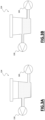
- Figure 1 schematically illustrates a simplified (not-in-scale) cross-sectional side view of a washing appliance 100 in which concepts according to the embodiments of the present invention can be applied.
- the washing appliance 100 is a dishwasher.
- the dishwasher 100 comprises a number of well known hydraulic, electronic, electric and electromechanical components - however, for the sake of description ease and conciseness, only those being relevant for understanding the invention will be introduced and discussed in the following.
- the operation of these (not illustrated) electronic, electric and electromechanical components of the dishwasher 100 is controlled by one or more control units (only one illustrated in Figure 1 and identified with reference 105).
- the dishwasher 100 comprises a tub 110 configured to house items to be washed, such as dishes, cutlery, drinking glasses.
- one or more baskets are provided in the tub 110 for accommodating the items to be washed.
- the tub 110 is provided with a first, upper, basket 112, a second, middle, basket 114 and a third, lower, basket 116.
- the first basket 112 may be configured to accommodate cutlery
- the second and third baskets 114, 116 may be configured to accommodate other kinds of items to be washed, such as plates and drinking glasses.
- a door (not shown in the figure) is hingedly mounted to a front portion of the dishwasher 100 to provide selective access to the tub 110, and accordingly to the baskets 112, 114, 116.
- detergent in the form of tablets, liquid, or powder is stored in a corresponding detergent compartment located at an inside portion of the door (not shown) of the dishwasher 100.
- said stored detergent is controllably discharged, under the control of the control unit 105, into the tub 110 according to user-selected washing cycle being carried out by the dishwasher 100 and/or by a phase of said user-selected washing cycle being carried out by the dishwasher 100.
- the dishwasher 100 comprises an inlet valve 120 operable by the control unit 105 to be selectively switched between an open condition for causing washing fluid (e.g ., fresh water provided by a water inlet 122) to be loaded into the tub 110 and a closed condition for preventing washing fluid be fed to the dishwasher 100.
- washing fluid e.g ., fresh water provided by a water inlet 122
- the dishwasher 100 comprises a sump, globally identified in Figure 1 with reference 124, in fluid communication with a bottom portion of the tub 110, so that washing fluid reaching the tub 110 - such as fresh water loaded by the inlet valve 120 - is collected in said sump 124.
- Fresh water collected in the sump 124 is also mixed therein with the detergent discharged from the detergent compartment, so that the resulting washing fluid - also referred to as process water - turns into a mixture of water and detergent.
- the dishwasher 100 further comprises a circulation pump 130 in fluid communication with the sump 124 - and therefore with the tub 110 - and configured to circulate the washing fluid in the tub 110 during a user-selected washing cycle being carried out by the dishwasher 100 and/or by a phase of said user-selected washing cycle being carried out by the dishwasher 100.
- the circulation pump 130 is configured to circulate the washing fluid in the tub 110 when the circulation pump 130 is controlled by the control unit 105 to rotate in a first, forward, direction.
- each spray device 132, 134, 136 comprises a respective wash arm provided with nozzles for causing washing fluid being sprayed onto the items to be washed housed in the respective basket 112, 114, 116.
- the dishwasher 100 advantageously comprises a flow control device 140 configured to receive the washing fluid pumped by the circulation pump 130 when the latter is controlled to rotate in the forward direction, and to connect - under the control of the control unit 105 - one or more selected spray device(s) 132, 134, 136 to the circulation pump 130 in order to provide the washing fluid received by the circulation pump 130 to said selected spray device(s) 132, 134, 136.
- the washing fluid pumped by the circulation pump 130 may be selectively recirculated in the washing tub 110 through one or more selected spray device(s) 132, 134, 136.
- a filter 150 is advantageously provided at the sump 124 for filtering soil from the washing fluid before the latter is recirculated into the washing tub 110 by the circulation pump 130 through the spray device(s) 132, 134, 136.
- the dishwasher 100 further comprises a drain pump 160 configured to be operated by the control unit 105 in an activated condition for causing washing fluid in the sump 124 to be drained from the dishwasher 100, e.g ., through a corresponding drain outlet 162, and in a deactivated condition for preventing washing fluid in the sump 124 to be drained from the dishwasher 100.
- a drain pump 160 configured to be operated by the control unit 105 in an activated condition for causing washing fluid in the sump 124 to be drained from the dishwasher 100, e.g ., through a corresponding drain outlet 162, and in a deactivated condition for preventing washing fluid in the sump 124 to be drained from the dishwasher 100.
- the circulation pump 130 is driven by a corresponding motor system 165 (for example comprising a respective electric motor driven by a respective motor driving unit comprising a respective inverter and a TRIAC) controlled by the control unit 105.
- a corresponding motor system 165 for example comprising a respective electric motor driven by a respective motor driving unit comprising a respective inverter and a TRIAC
- the drain pump 160 is driven by a corresponding motor system 166 (for example comprising a respective electric motor driven by a respective motor driving unit comprising a respective inverter and a TRIAC) controlled by the control unit 105.
- a corresponding motor system 166 for example comprising a respective electric motor driven by a respective motor driving unit comprising a respective inverter and a TRIAC
- circulation pump 130 and the drain pump 160 may be controlled to operate concurrently and independently.
- the concepts of the present invention can be applied to cases in which a single motor system is provided, configured to selectively drive the circulation pump 130 or the drain pump 160.
- the circulation pump 130 and the drain pump 160 cannot be controlled to operate concurrently.
- the electric motors of the circulation pump 130 and of the drain pump 160 may be driven by a same inverter.
- a single motor system may be provided comprising the electric motors of the two pumps, the respective TRIACs, and a single inverter.
- Said single inverter may be selectively coupled (e.g., by means of respective switches) to the TRIAC controlling the motor of the circulation pump 130 or to the TRIAC controlling the motor of the drain pump 160.
- the dishwasher 100 further comprises at least one pump sensor unit 190 configured to measure an electromechanical parameter of the circulation pump 130, such as an electric current drawn by the circulation pump 130, a voltage across the circulation pump 130, the power consumption of the circulation pump 130 and/or a torque of the circulation pump 130, and provide said measure to the control unit 105.
- an electromechanical parameter of the circulation pump 130 such as an electric current drawn by the circulation pump 130, a voltage across the circulation pump 130, the power consumption of the circulation pump 130 and/or a torque of the circulation pump 130, and provide said measure to the control unit 105.
- the dishwasher 100 further comprises a water softening system 195 (for example connected between the water inlet 122 and the inlet valve 120) configured to reduce hardness of water fed to the appliance through the water inlet 122 and used for generating the washing fluid.
- the water softening system 195 comprises a container containing a water softening agent (e.g., a ion-exchange resin) capable of reducing hardness of water by promoting exchange of the minerals dissolved in water causing hardness (e.g ., calcium and magnesium) for a soft mineral that does not build up on surfaces, such as sodium.
- a water softening agent e.g., a ion-exchange resin
- the water softening system 195 comprises a (refillable) container for storing a regenerating agent, usually salt (e.g ., Sodium chloride salt), to be used for regenerating the exhausted softening agent during a water softening agent regeneration procedure.
- a regenerating agent usually salt (e.g ., Sodium chloride salt)
- control unit 105 is configured to manage the operation of the dishwasher 100 by carrying out proper software/firmware routines installed/stored in one or more memory units comprised in or associated to the control unit 105.
- Figure 2 illustrates in terms of functional blocks some of the routines that can be carried out by the control unit 105 for controlling the operations of the dishwasher according to an embodiment of the present invention.
- routines may be carried out by the control unit 105 concurrently with and/or in alternative to other routines. Moreover, at least some of the routines may interact with other routines, with the operation of a routine that may influence the operation of one or more other different routines.
- routines are advantageously configured to allow the control unit 105 to efficiently control the operation of the dishwasher 100 without the need that the dishwasher 100 is equipped with a pressure sensor for the determination of the level of washing fluid inside the tub 110. In this way, a correct and reliable operation of the dishwasher 100 can be guaranteed even if the dishwasher is lacking of a pressure sensor for the determination of the level of washing fluid inside the tub 110.
- a routine that can be carried out by the control unit 105 hereinafter also referred to as "washing cycle routine" and identified in Figure 2 with reference 210, provide for controlling the hydraulic, electronic, electric and electromechanical components of the dishwasher 100 for performing user-selected washing cycles.
- the washing cycle routine 310 may provide for controlling the discharge of detergent into the tub 110, set a target speed TS for the recirculation pump 130, selects the activation of one or more spray device(s) 132, 134, 136, set the temperature of the washing fluid, and so on.
- control unit 105 hereinafter also referred to as "circulation pump operative state routine" and identified in Figure 2 with reference 220 provides for allowing the control unit 105 to determine an operative state of the circulation pump 130 between:
- a saturation state is determined when the amount of washing fluid in the tub is sufficient or high enough to prevent air from being drawn out by the circulation pump 130
- a starvation state is determined when the amount of washing fluid in the tub is insufficient or not sufficient or not high enough to prevent air from being drawn out by the circulation pump 130.
- control unit 105 is configured to determine the operative state of the circulation pump 130 between the saturation state and the starvation state based on at least one electromechanical parameter of the circulation pump 130 sensed by the pump sensor unit 190, such as for example at least one among:
- the behavior of these electromechanical parameters of the circulation pump 130 is influenced by the operative state (saturation or starvation) of the circulation pump 130. Having the circulation pump that is operating at a certain speed SC, a starvation state is determined when the current value of the electric current drawn by the circulation pump 130 is subjected to a drop. Similar considerations apply by considering other electromechanical parameters of the circulation pump 130, such as the voltage, the power or the torque.
- the circulation pump 130 is in the saturation state, with an amount of washing fluid in the sump 124 that is sufficient to prevent air from being drawn out by the circulation pump 130.
- the circulation pump 130 is in the starvation state, since it is sucking air during its operation because of an insufficient amount of washing fluid in the sump 124.
- controlled circulation routine provides for efficiently controlling the current speed SC of the circulation pump 130 based on an indication of a target speed TS for the recirculation pump 130.
- the controlled circulation routine 230 will be described in greater detail in the following of the description.
- a further routine that can be carried out by the control unit 105 hereinafter also referred to as "fill to speed routine" and identified in Figure 2 with reference 240, provides for controlling the inlet valve 120 to load in the tub 110 amounts of washing fluid dosed in such a way to allow a correct operation of the dishwasher 100 when the latter is operating with the circulation pump 130 at a circulation pump speed SC based on said target speed TS.
- the fill to speed routine 240 will be described in greater detail in the following of the description.
- drain to speed routine 250 another routine that can be carried out by the control unit 105, hereinafter also referred to as “drain to speed routine” and identified in Figure 2 with reference 250, provides for controlling the drain pump 160 to drain out from the tub 110 (and from the dishwasher 100) amounts of washing fluid dosed in such a way to allow a correct operation of the dishwasher 100 when the latter is operating with the circulation pump 130 at a circulation pump speed SC based on said target speed TS.
- the drain to speed routine 250 will be described in greater detail in the following of the description.
- a further routine that can be carried out by the control unit 105 hereinafter also referred to as "drain to empty procedure" and identified in Figure 2 with reference 270, provides for controlling the drain pump 160 to drain out washing fluid so as to empty the tub 110 (and the sump 124).
- the drain to empty procedure 270 will be described in greater detail in the following of the description.
- another routine that can be carried out by the control unit 105 hereinafter also referred to as "fill to speed not empty", and identified in Figure 2 with reference 280, provides for controlling the inlet valve 120 to cause a correct filling of washing fluid in the tub 110 starting from a condition in which the sump 124 is assumed to be empty.
- another routine that can be carried out by the control unit 105 hereinafter also referred to as "inlet valve checking procedure" and identified in Figure 2 with reference 285, provides for verifying the correct operation of the inlet valve 120, and particularly to determine if the inlet valve 120 is subjected to a fault causing undesired leakages when in the closed condition.
- the inlet valve checking procedure 285 will be described in greater detail in the following of the description.
- routines 230, 240, 250 and 285 are configured to operate by taking into account the output produced by the routine 220, i.e., by taking into account the operative state of the circulation pump 130 (saturation state or starvation state).
- control unit 105 In the following sections of the description, some of the routines that can be carried out by the control unit 105 according to embodiment of the present invention will be described in greater detail.
- the controlled circulation routine 230 provides for causing the speed SC of the circulation pump 130 to increase towards the target speed TS with a first speed increase rate R1. If a starvation state of the circulation pump 130 is determined, and at the same time the inlet valve 120 is in the open condition (causing thus washing fluid being loaded into the tub 110) before the the speed SC of the circulation pump 130 reached the target speed TS, the speed SC of the circulation pump 130 is set to increase towards the target speed TS with a second speed increase rate R2 lower than the first speed increase rate R1.
- Figure 4A illustrates in terms of functional blocks a flow chart depicting the operations carried out by the control unit 105 when the controlled circulation routine 230 is being carried out according to an embodiment of the present invention.
- control unit 105 sets a first increase rate R1 for the speed SC of the circulation pump 130 (block 405).
- the controlled circulation routine 230 enters in a so-called "initial speed ramp state" in which the control unit 105 causes the speed SC of the circulation pump 130 to increase - from a starting value, e.g ., equal to zero if the circulation pump 130 is stopped - towards the target speed TS with said first increase rate R1 (block 406).
- the value of the target speed TS is set by the washing cycle procedure 210, depending on a user-selected washing cycle (and/or based on a phase thereof) being currently carried out by the dishwasher 100.
- said first increase rate R1 is higher than 70 RPM/s, such as for example equal to 80 RPM/s.
- the control unit 105 if a starvation state of the circulation pump 130 is determined (by the circulation pump operative state routine 220) before the speed SC of the circulation pump 130 reached the target speed TS (block 408), the control unit 105 initializes a timer TC (block 410) and starts the timer TC to count a predetermined time period (e.g., 200 ms). Then, the controlled circulation routine 230 enters in a so-called "starving state" (block 412), in which the speed SC of the circulation pump 130 is caused to increase by the control unit 105 with the actually set increase rate while the circulation pump 130 is determined to be in the starvation state.
- a starvation state of the circulation pump 130 is determined (by the circulation pump operative state routine 220) before the speed SC of the circulation pump 130 reached the target speed TS (block 408), the control unit 105 initializes a timer TC (block 410) and starts the timer TC to count a predetermined time period (e.g., 200 m
- the control unit 105 checks if the inlet valve 120 is in the open condition or in the closed position (block 416). According to an embodiment of the present invention, the condition (open or closed) of the inlet valve 120 is set by the fill to speed routine 240.
- the control unit 105 causes the increasing rate of the speed SC of the circulation pump 130 to be set to zero, and causes the speed SC of the circulation pump 130 to be decreased by a corresponding decreasing amount DSC (block 418).
- the control unit 105 checks (block 420) if the highest value reached by the speed SC of the circulation pump 130 has been subjected to any increase for a corresponding time period (e.g., 45s). In case the highest value reached by the speed SC of the circulation pump 130 did not increase during said time period (exit branch N of block 420), the control unit 105 stops (block 422) the circulation pump 130 for a time interval, such as for 5s, for removing air from the circulation pump 130, and then the operations flow returns to block 405.
- a time period e.g. 45s
- the control unit 105 causes the speed SC of the circulation pump 130 to increase towards the target speed TS with a second increase rate R2 lower than the first increase rate R1 (block 430).
- said decreasing amount DSC is equal to 100 RPM/s.
- said second increase rate R2 is lower than 10 RPM/s, such as for example equal to 5 RPM/s.
- control unit 105 reinitializes the timer TC and starts the timer TC to count a further time period (block 432), for example 4s.
- a saturation state of the circulation pump 130 is determined by the circulation pump operative state routine 220 before the timer TC elapses (block 434), after a further time period is expired (e.g., 2s), the controlled circulation routine 230 enters in a so-called "saturating state" (block 436), in which the speed SC of the circulation pump 130 is caused to increase by the control unit 105 with a third increase rate R3 lower than the first increase rate R1 and higher than the second increase rate R2 while the circulation pump 130 is determined to be in the saturation state.
- the value of the third increase rate R3 depends on the condition (open/closed) of the inlet valve 120.
- the third increase rate R3 is higher than 50 RPM/s, for example equal to 60 RPM/s, while if the inlet valve is in the closed condition, the third increase rate R3 is lower than 50 RPM/s, for example equal to 40 RPM/s.
- the control unit 105 When carrying out the controlled circulation routine 230 according to the embodiments of the invention illustrated in Figure 4A , the control unit 105 tries to cause the circulation pump 130 to operate at the target speed TS by increasing the speed SC of the circulation pump 130 starting from a starting value with a corresponding speed increase rate (blocks 405, 406).
- the target speed TS can be reached without causing the circulation pump 130 to enter in the starvation state (block 440). If the target speed TS cannot be reached without causing a starvation state of the circulation pump 130 (block 408), the control unit 105 controls the speed SC to reach the highest speed SC capable of maintaining the circulation pump 130 in the saturation state. This is done by slowly increasing the speed SC until a starvation state of the circulation pump 130 is detected, and then:
- Figure 4B is an exemplary time diagram showing how the speed SC of the circulation pump 130 varies over time under the control of the control unit 105 when the latter is carrying out the controlled circulation routine 230 according to an embodiment of the present invention.
- the circulation pump 130 is initially turned off, and therefore the speed SC is equal to zero.
- the controlled circulation routine 230 is started, and the control unit 105 causes the circulation pump 130 to increase the speed SC of the circulation pump 130 with a corresponding first speed increase rate R1 (blocks 405, 406).
- a starvation state of the circulation pump 130 is determined, before the speed SC of the circulation pump 130 reached the target speed TS (block 408).
- the control unit 105 initializes and starts the timer TC to count a predetermined time period (block 410).
- the timer TC expires at time tc(3) before a saturation state of the circulation pump 130 is determined (block 414).
- the inlet valve 120 is in the open condition (exit branch Y of block 416), and therefore the control unit 105 verifies if the highest value reached by the speed SC of the circulation pump 130 has been subjected to any increase during a past time period from time tc(3) (block 420).
- controlled circulation routine 230 it is therefore possible to efficiently control the current speed SC of the circulation pump 130 to reach a value corresponding to a requested target speed TS without requiring the presence of a pressure sensor for the determination of the level of washing fluid currently inside the tub 110.
- the fill to speed routine 240 provides for causing the inlet valve 120 to be opened in order to fill washing fluid in the tub 110 when the speed SC of the circulation pump 130 is lower than or equal to the target speed TS if a starvation state of the circulation pump 130 is determined.
- the fill to speed routine 240 also provides for causing the inlet valve 120 to be closed if a saturation state of the circulation pump 130 is determined.
- the closure of the valve is delayed in case the speed SC of the circulation pump 130 is lower than the target speed TS by a sufficiently large amount.
- Figure 5 illustrates in terms of functional blocks a flow chart depicting the operations carried out by the control unit 105 when the fill to speed routine 240 is being carried out according to an embodiment of the present invention.
- the fill to speed routine 240 may switch between two different states, and namely a so-called “valve open state” (block 502) corresponding to an open condition of the inlet valve 120 for causing new washing fluid to be fed to the dishwasher 100 for being loaded in the tub 110 and a so-called “valve closed state” (block 504) corresponding to a closed condition of the inlet valve 120 for preventing new washing fluid to be fed to the dishwasher 100.
- a so-called “valve open state” block 502
- valve closed state block 504
- the initial state of the fill to speed routine 240 depends on the current state of the inlet valve 120.
- valve closed state in which the inlet valve 120 is in the closed condition
- the control unit 105 causes the inlet valve 120 to switch to the open condition for causing new washing fluid to be fed in the tub 110 (block 507).
- the fill to speed routine 240 switches to the valve open state (going to block 502).
- a saturation state of the circulation pump 130 is determined (block 508), when the speed SC of the circulation pump 130 is equal to or higher than the target speed TS (block 509), the fill to speed routine 240 terminates.
- the control unit 105 when the fill to speed routine 240 is in the valve open state (block 502), and a starvation state of the circulation pump 130 is determined (block 510), when the speed SC of the circulation pump 130 is higher than the target speed TS (block 512), the control unit 105 causes the inlet valve 120 to switch to the closed condition for preventing new washing fluid be fed to the dishwasher 100 (block 514). Then the fill to speed routine 240 switches the valve closed state (going to block 504).
- the control unit 105 when the fill to speed routine 240 is in the valve open state (block 502), and a saturation state of the circulation pump 130 is determined (block 516), when the speed SC of the circulation pump 130 is equal to or higher than the target speed TS (block 518), the control unit 105 causes the inlet valve 120 to switch to the closed condition for preventing new washing fluid be fed to the dishwasher 100 (block 514). Then, the fill to speed routine 240 switches to the valve closed state (going to block 504).
- the control unit 105 checks (block 522) if the speed SC is however close to ( e.g., only slightly lower than) the target speed TS, or if said speed SC is still far from ( e.g ., substantially lower than) the target speed TS.
- the control unit 105 directly causes the inlet valve 120 to switch to the closed condition for preventing new washing fluid be fed to the dishwasher 100 (block 514). Then, the fill to speed routine 240 switches to the valve closed state (going to block 504).
- the control unit 105 if the difference between the target speed TS and the speed SC of the circulation pump 130 is higher than a speed threshold THC (exit branch Y of block 522), the control unit 105 causes a delayed switching of the inlet valve 120 to the closed condition. According to an embodiment of the invention, the control unit 105 causes the inlet valve 120 to switch to the closed position only after a delay interval DIF is expired.
- said speed threshold THC is higher than 100 RPM and lower than 300 RPM, for example is equal to 200 RPM.
- the duration of the delay interval DIF depends on the difference ⁇ F between the target speed TS and the speed SC of the circulation pump 130.
- the control unit 105 set the delay interval DIF (block 524) to a value that is proportional to the difference ⁇ F between the target speed TS and the speed SC of the circulation pump 130.
- the delay interval DIF is set to a maximum predetermined value MDIF if the difference ⁇ F is excessively large.
- the control unit 105 sets the delay interval DIF to the minimum value between:
- MDIF may be set to 10000 ms and PF may be set to 20 ms.
- the control unit 105 when the delay interval DIF is expired (block 526), the control unit 105 causes the inlet valve 120 to switch to the closed condition for preventing new washing fluid be fed to the dishwasher 100 (block 514). Then, the fill to speed routine 240 switches to the valve closed state (going to block 504).
- the fill to speed routine 240 it is possible to efficiently control the inlet valve 120 to load in the tub 110 amounts of washing fluid dosed in such a way to allow a correct operation of the dishwasher 100 when the latter is operating with the circulation pump 130 at a circulation pump speed SC based on said target speed TS , without requiring the presence of a pressure sensor for the determination of the current level of washing fluid inside the tub 110.
- the controlled circulation routine 230 and the fill to speed routine 240 are two routines that can be expediently carried out by the control unit 105 concurrently, since each one of the two routines requires, among its inputs, something that can be output by the other routine.
- the controlled circulation routine 230 requires to receive the indication of the target speed TS, an indication of the operative state PC (starvation state or saturation state) of the circulation pump 130, and an indication of the condition VC (open condition or closed condition) of the inlet valve 120.
- the fill to speed routine 240 requires to receive the indication of the target speed TS, the indication of the operative state PC of the circulation pump 130, and an indication of the current speed SC of the circulation pump 130.
- the controlled circulation routine 230 and the fill to speed routine 240 may be advantageously executed concurrently, using the indication of the condition VC of the inlet valve 120 set by the fill to speed routine 240 as an input for the controlled circulation routine 230, and using the indication of the speed SC of the circulation pump 130 set by the controlled circulation routine 230 as an input for the fill to speed routine 240.
- each one of said routines may operate by using a respective different target speed TS.
- control unit 105 may control the speed SC of the circulation pump 130 (by running the controlled circulation routine 230) based on:
- control unit 105 may control the condition VC of the inlet valve 120 (by running the fill to speed routine 240) based on:
- the first target speed TS1 is set to a value higher than the value of the second target speed TS2 (e.g., TS1 is set to 2000 RPM, and TS2 is set to 1800 RPM), as long as the current speed SC of the circulation pump 130 is equal to or lower than TS2, both the two routines are carried out by the control unit 105.
- the speed SC of the circulation pump 130 is higher than TS2, the fill to speed routine 240 is prevented to cause the opening of the inlet valve 120.
- the drain to speed routine 250 provides for performing partial drains of washing fluid by causing the drain pump 160 to be activated to drain amounts of washing fluid out from the tub 110 (and from the dishwasher 100) when the speed SC of the circulation pump 130 is higher than or equal to the target speed TS if a saturation state of the circulation pump 130 is determined.
- Figure 7 illustrates in terms of functional blocks a flow chart depicting the operations carried out by the control unit 105 when the drain to speed routine 350 is being carried out according to an embodiment of the present invention.
- the drain to speed routine 250 may switch between two different states, and namely a so-called “drain off state” (block 702) corresponding to a deactivated condition of the drain pump 160 for preventing washing fluid in the tub 110 to be drained out from the dishwasher 100, and a so-called “drain on state” (block 704) corresponding to an activated condition of the drain pump 160 for causing washing fluid to be drained out from the tub 110.
- a drain off state block 702
- drain on state block 704
- the control unit 105 causes the drain pump 160 to switch to the activated condition (block 710) for causing washing fluid to be drained out from the tub 110. Then, the drain to speed routine 250 switches to the drain on state (going to block 704).
- the drain to speed routine 250 when the drain to speed routine 250 is in the drain off state (block 702), with the drain pump 160 that is in the deactivated condition, if a starvation state of the circulation pump 130 is determined (block 712), when the speed SC of the circulation pump 130 is lower than the target speed TS (block 714), the drain to speed routine 250 terminates.
- the control unit 105 causes the drain pump 160 to switch to the deactivated condition (block 716) for preventing washing fluid to be drained out from the tub 110. Then, the drain to speed routine 250 switches to the drain off state (going to block 702).
- the control unit 105 causes the drain pump 160 to switch to the deactivated condition (block 716) for preventing washing fluid to be drained out from the tub 110. Then, the drain to speed routine 250 switches to the drain off state (going to block 702).
- the drain to speed routine 250 it is therefore possible to carry out partial drains of washing fluid by efficiently control the drain of amounts of washing fluid from the tub 110 (and from the dishwasher 100) dosed in such a way to allow a correct operation of the dishwasher 100 when the latter is operating with the circulation pump 130 at a circulation pump speed SC based on said target speed TS , without requiring the presence of a pressure sensor for the determination of the current level of washing fluid inside the tub 110.
- drain to speed routine 250 since the drain to speed routine 250 according to the embodiments of the invention illustrated above requires that the circulation pump 130 and the drain pump 160 are driven concurrently, said routine can be implemented only in case the the circulation pump 130 and the drain pump 160 are driven by respective different and independent motor systems (i.e ., the motor systems 165 and 166).
- the drain to empty routine 270 provides for activating the drain pump 160 for draining washing fluid from the tub 110 (and from the sump 124) until an empty condition of the sump 124 is detected in which the sump 124 substantially does not contain washing fluid.
- the empty condition of the sump 124 is detected by controlling the circulation pump 130 to rotate in a second, backward, direction (opposite to the first, forward direction normally employed for circulating the washing fluid in the tub 110, so that no circulation of washing fluid in the tub 110 occurs), collecting samples of an electromechanical parameter of the circulation pump 130 sensed by the pump sensor unit 190 during the rotation in the backward direction, and then by comparing said collected samples with a threshold ETH.
- said electromechanical parameter of the circulation pump 130 is an electric current drawn by the circulation pump 130, a voltage across the circulation pump 130, the power consumption of the circulation pump 130 and/or a torque of the circulation pump 130.
- control unit 105 is configured to calculate an energy value EV indicative of an electric energy consumed by the circulation pump 130 during the rotation in the backward direction based on the collected samples, and then by comparing said calculated energy value EV with the threshold ETH. If the energy value EV is higher than the threshold ETH, it means that there is still an amount of washing fluid in the tub 110 such to cause the circulation pump 130 to consume a non negligible amount of energy in order to be able to rotate.
- Figure 8 illustrates in terms of functional blocks a flow chart depicting the operations carried out by the control unit 105 when the drain to empty routine 270 is being carried out according to an embodiment of the present invention.
- control unit 105 sets to zero an energy counter EC indicative of a number of times in a row the energy value EV has been determined to be lower than the threshold ETH, and set a minimum energy threshold Emin to a very large value (block 802).
- control unit 105 controls the drain pump 160 to switch to the activated condition for causing washing fluid in the sump 124 to be drained from the dishwasher 100, and controls the circulation pump 130 to rotate in the backward direction (block 804).
- control unit 105 collects a set of samples of an electromechanical parameter of the circulation pump 130 sensed by the pump sensor unit 190, such as the electric current I drawn by the circulation pump 130 (similar considerations apply in case a different electromechanical parameter is used, such as the voltage, the power or the torque of the circulation pump 130) and accordingly calculates a corresponding energy value EV (block 806).
- control unit 105 calculates the energy value EV by summing the samples of the collected set.
- similar considerations apply in case the energy value EV is calculated using the samples in a different way.
- control unit 105 compares the calculated energy value EV with the threshold ETH (block 810).
- the control unit 105 reset the energy counter EC to zero (block 820), and set the minimum energy threshold Emin to the minimum between the current value of the minimum energy threshold Emin and the last calculated energy value EV (bock 822).
- control unit 105 causes the recirculation pump 130 to be turned off (block 823), and, after a wating interval, such as 5s, to be turned on again for rotating in the backward direction (going back to block 804).
- the control unit 105 increases (e.g., by one) the energy counter EC (block 824), and then compares the just increased energy counter EC with an energy counter threshold ECTH (block 826).
- the energy counter threshold ECTH is equal to 2. However, similar considerations apply in case the energy counter threshold ECTH has a different value.
- the energy counter EC if the energy counter EC is higher than the energy counter threshold ECTH (exit branch Y of block 826), it means that the energy value EV has been determined to be lower than the threshold ETH for a number of times in a row sufficient to avoid incorrect determinations of empty conditions of the sump 124 due to spurious variations of the speed SC of the circulation pump 130 independent from the actual level of the washing fluid inside the sump 124.
- the control unit 105 carries out a stability check for determining if the current energy consumption of the circulation pump 130 is on a stable low value or not by comparing the last calculated energy value EV with the minimum energy threshold Emin (block 828).
- the operations flow goes to block 822 if the last calculated energy value EV plus an energy hysteresis value EH is lower than the energy counter threshold ECTH (exit branch N of block 828), it means that the current energy consumption of the circulation pump 130 is at a value that is not sufficiently low and stable to avoid incorrect determinations of empty conditions of the sump 124, and therefore the operations flow goes to block 822.
- the control unit 105 determines an empty condition of the sump 124, and thus controls the drain pump 160 to switch to the deactivated condition (block 830).
- the drain to empty routine 270 it is therefore possible to efficiently empty the sump 124 (and therefore the tub 110) and turning off the drain pump 160 when the empty condition of the sump 124 is determined, without requiring the presence of a pressure sensor for the determination of the current level of washing fluid inside the tub 110.
- drain to empty routine 270 since the drain to empty routine 270 according to the embodiments of the invention illustrated above requires that the circulation pump 130 and the drain pump 160 are driven concurrently, said routine can be implemented only in case the the circulation pump 130 and the drain pump 160 are driven by respective different and independent motor systems ( i.e ., the motor systems 165 and 166).
- the fill to speed not empty routine 280 provides for controlling the circulation pump 130 to rotate in the backward direction. Then, the inlet valve 120 is caused to switch to the open condition for causing washing fluid be fed into the tub 110 (and therefore into the tub 124) while the circulation pump 130 is rotating backward. Presence of washing fluid inside the sump is determined based on a comparison between an electric parameter of the circulation pump 130 during a first time period TP1 (occurring before the opening of the inlet valve 120) and the electric parameter of the circulation pump 130 during a second time period TP2 (occurring after the opening of the inlet valve 120). A filled condition of the sump 124 is determined if inside the sump 124 there is an amount of washing fluid that is sufficient to cause a sufficiently large increase of the electric parameter of the circulation pump 130 from the first time period TP1 to the second time period TP2.
- said electric parameter of the circulation pump 130 is an electric current I drawn by the circulation pump 130.
- a comparison is made between an electric current I drawn by the circulation pump 130 during the first time period TP1 and an electric current I drawn by the circulation pump 130 during the second time period TP2.
- the concepts of the present invention can be applied to cases in which a different electric parameter of the circulation pump 130 is considered, such as a voltage developed across the circulation pump 130 or the power consumption of the circulation pump 130.
- Figure 9 illustrates in terms of functional blocks a flow chart depicting the operations carried out by the control unit 105 when the fill to speed not empty routine 280 is being carried out according to an embodiment of the present invention.
- the control unit 105 controls the circulation pump 130 to rotate in the backward direction at a first reverse speed CS1 (block 902).
- the first reverse speed CS1 may be set to -1000 RPM (the minus sign shows that the circulation pump 130 is rotating in the backward direction, i.e., a direction opposite to the first, forward direction normally employed for circulating the washing fluid in the tub 110, so that no circulation of washing fluid in the tub 110 occurs).
- control unit 105 waits until the electric current I drawn by the circulation pump 130 - sensed by the pump sensor unit 190 - reaches a stable value (block 904), for example by observing the fluctuations of said current.
- control unit 105 calculates an average current value IAV corresponding to the average of the electric current I drawn by the the circulation pump 130 during a first time period TP1 (block 906).
- control unit 105 causes the inlet valve 120 to switch to the open condition (block 910), for causing washing fluid to be fed into the tub 110 (and therefore, into the sump 124).
- the control unit 105 is configured to determine the presence of washing fluid inside the sump 124 (filled condition) when the electric current I drawn by the circulation pump 130 - sensed by the pump sensor unit 190 - during a second time period TP2 after the inlet valve 120 switched to the open condition is higher than the average current value IAV by a first hysteresis threshold ITH1 (block 920).
- the hysteresis threshold ITH1 is set to a value higher than 1 mA and lower than 4 mA, such as for example 2 mA.
- control unit 105 causes the inlet valve 120 to switch to the closed condition, and to cause the circulation pump 130 to stop (block 925).
- the fill to speed not empty routine 280 is based on the assumption that the sump 124 is initially empty. In order to avoid incorrect results in case the sump 124 was already containing washing fluid at the beginning of the routine, for example because the average current value IAV has a large value, according to an embodiment of the present invention, the fill to speed not empty routine 280 is modified to further provide for the following operations.
- the control unit 105 causes the inlet valve 120 to switch to the open condition
- the control unit 105 causes the circulation pump 130 to rotate in the backward direction at a second reverse speed CS2 having an absolute value higher than an absolute value of said first reverse speed CS (block 940).
- the second reverse speed CS2 may be set to -2000 RPM.
- the control unit 105 is configured to determine the presence of washing fluid inside the sump 124 (filled condition) when the electric current I drawn by the circulation pump 130 - sensed by the pump sensor unit 190 - during a third time period TP3 after the second time period TP2 is higher than the average current value IAV by a second hysteresis threshold ITH2 (block 942).
- the second hysteresis threshold ITH2 is set to a value higher than the first hysteresis threshold ITH1.
- the second hysteresis threshold ITH2 is higher than 10 mA and lower than 20 mA, such as for example 15 mA.
- control unit 105 is then configured to cause the inlet valve 120 to switch to the closed condition, and to cause the circulation pump 130 to stop (block 944).
- controlling the circulation pump 130 to rotate in the backward direction at a too large reverse speed may cause problems in case a water softening agent regeneration procedure has been recently carried out by the water softening system 195 without having been followed by a complete drain operation. Indeed, in this case, brine comprising salt is still present in the sump 124, and by running the circulation pump 130 to rotate in the backward direction at a too large reverse speed could cause salt being sprayed in the tub 110, soiling the walls of the latter and the baskets 132, 134, 136.
- this problem is solved by preventing the control unit 105 to cause the circulation pump 130 to rotate in the backward direction at the second reverse speed CS2 in case the water softening system 195 has been subjected to a water softening agent regeneration procedure and no drain of the washing fluid inside the sump 124 has been carried out after said water softening agent regeneration procedure.
- control unit 105 checks if the water softening system 195 has been subjected to a water softening agent regeneration procedure and no drain of the washing fluid inside the sump 124 has been carried out after said a water softening agent regeneration procedure (block 950).
- control unit 105 causes the inlet valve 120 to switch to the closed condition, and cause the circulation pump 130 to stop (block 960).
- the washing fluid included in the sump 124 (comprising salt) is drained out from the dishwasher 100 (block 965), for example using the previously described drain to empty routine 270, and then the operation flows returns to block 902.
- the inlet valve checking procedure 285 provides for opening the inlet valve 120 to load washing fluid into the tub 110 while the circulation pump 130 is operated to reach a first target flow rate TFR1, and then closing the inlet valve 120 when a saturation state of the circulation pump 130 is determined with the circulation pump 130 that is operating at the first target flow rate TFR1.
- the circulation pump 130 is controlled to operate at a second flow rate TFR2 higher than the first flow rate TFR1. If a starvation state of the circulation pump 130 is determined while the circulation pump 130 is operating at the second flow rate TFR2, the inlet valve 120 is determined to not be affected by leakages when in the closed condition.
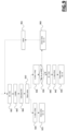
- Figure 10A illustrates in terms of functional blocks a flow chart depicting the operations carried out by the control unit 105 when the inlet valve checking routine 285 is being carried out according to an embodiment of the present invention.
- control unit 105 controls the inlet valve to switch to the open condition for causing washing fluid to be fed into the tub 110 (block 1002).
- the control unit 105 controls the circulation pump 130 to operate for reaching a first target flow rate TFR1 (block 1004).
- the flow rate of the circulation pump 130 may be set by controlling the speed SC of the latter, and/or by selecting which spray devices 132, 134, 136 to connect (through the flow control device 140) to the circulation pump 130.
- the speed SC of the circulation pump 130 is varied while maintaining a same spray condition SPC in which a same set of spray devices 132, 134, 136 is connected to the circulation pump 130, the higher the speed SC of the circulation pump 130, the higher the flow rate of the circulation pump 130.
- the flow rate of the circulation pump 130 can be varied by altering the spray condition SPC of the spray devices 132, 134, 136.
- the flow rate of the circulation pump 130 operating at a certain speed SC while connected to only the two spray devices 134, 136 is lower than the flow rate of the circulation pump 130 operating at the same speed SC when connected to all the three spray devices 132, 134, 136, since in the former spray condition SPC, only two spray devices 134, 136 need to be fed by the circulation pump 130, while in the latter spray condition SPC a higher number (3) of spray devices 132, 134, 136 need to be fed by the circulation pump 130.
- the flow rate of the circulation pump 130 operating at a certain speed SC while connected to only the spray device 136 is lower than the flow rate of the circulation pump 130 operating at the same speed SC when connected to only the spray device 132, since in the latter spray condition SPC the washing fluid pumped by the circulation pump 130 has to reach an higher altitude (to reach the spray device 132) compared to the one corresponding to the former spray condition SPC (to reach the spray device 136).
- control unit 105 controls the inlet valve 120 to switch to the closed condition (block 1006) when both the two following conditions are true:
- the amount of washing fluid that has been loaded into the tub 110 with the operations corresponding to blocks 1002 - 1006 is sufficient to allow the circulation pump 130 to operate at the first target flow rate TFR1 without causing a starvation state of the circulation pump 130.
- the circulation pump 130 is operated by the control unit to reach the first target flow rate TFR1 by varying the speed SC of the circulation pump 130 to reach a corresponding first target speed TSC1.
- this is carried out by having the control unit 105 that controls the speed SC of the circulation pump 130 according to the previously described controlled circulation routine 230 based on a target speed equal to the first target speed TSC1.
- the amount of washing fluid fed into the tub 110 sufficient to allow the circulation pump 130 to operate at the first target flow rate TFR1 without causing a starvation state of the circulation pump 130 corresponding to blocks 1004 and 1006 is set by having the control unit 105 that controls the inlet valve 120 according to the previously described fill to speed routine 240 based on a target speed equal to the first target speed TSC1. Therefore, according to an embodiment of the present invention, the control unit 105 is configured to control the inlet valve 120 to switch to the closed condition (block 1006) when the two following conditions are both true:
- the fill to speed routine 240 provides that the inlet valve 120 is closed also before the speed SC reached the target speed if a starvation state of the circulation pump 130 is determined, intermediate closures and openings of the inlet valve 120 may occur after operations corresponding to block 1002 and before operations corresponding to block 1006.
- control unit 105 is configured to:
- the control unit 105 causes the circulation pump 130 to operate at a second target flow rate TFR2 higher than the first target flow rate TFR1 (block 1010).
- the circulation pump 130 is controlled to operate at the second target flow rate TFR2 for a corresponding time period, such as for example for about 45 seconds.
- control unit 105 controls the circulation pump 130 to operate at the second target flow rate TFR2 by causing the circulation pump 130 to increase its speed SC from the first target speed TSC1 to a second target speed TSC2 higher than the first target speed TSC1, and by keeping at the same time the spray devices 132, 134, 136 in a same spray condition SPC.
- control unit 105 controls the circulation pump 130 to operate at the second target flow rate TFR2 by maintaining the speed SC of the circulation pump 130 at the first target speed TSC1 and by controlling at the same time the flow control device 140 to modify the spray condition SPC of the spray devices 132, 134, 136 with respect to the spray condition SPC employed during the execution of the operations corresponding to blocks 1002 - 1006.
- the operations corresponding to blocks 1002 - 1006 may be carried out by having the flow control device 140 that connects the circulation pump 130 to two spray devices (e.g ., the spray devices 134 and 136), and the operations corresponding to block 1010 by having the flow control device 140 that connects the circulation pump 130 to all three spray devices 132, 134, 136.
- the concepts of the present invention can be also applied in case the passage from the first target flow rate TFR1 to the second target flow rate TFR2 is accomplished by varying both the speed SC of the circulation pump 130 and the spray condition SPC of the spray devices 132, 134, 136.
- the control unit 105 is configured to determine that the inlet valve 120 is not affected by leakages when the latter is in the closed condition (block 1014). Indeed, at the end of block 1006, the inlet valve 120 has been closed in such a way that the total amount of washing fluid loaded into the tub 110 is just sufficient to allow the circulation pump 130 to operate at the first target flow rate TFR1 without causing a starvation state of the circulation pump 130.
- the control unit 105 is configured to determine that the inlet valve 120 is affected by leakages when the latter is in the closed condition (block 1018).
- the control unit 105 determines that the inlet valve 120 is affected by leakages when in the closed condition
- the control unit is configured to generate a proper warning (block 1020), for example through an acoustic message, a visual message on a display of the dishwasher, or a warning message sent ( e.g ., through the Internet) to a smartphone of an user of the dishwasher 100.
- the control unit 105 stops the circulation pump 130 (block 1022) and then drains the washing fluid out from the tub 110 by causing the drain pump 160 to switch to the activated condition for a predetermined time period ITP (block 1024).
- At least the operations corresponding to blocks 1002 - 1010 can be reiterated at least once after the predetermined time period ITP is expired.
- control unit 105 is configured to carry out the operations corresponding to block 1022 and 1024 after each reiteration of the operations corresponding to blocks 1002 - 1010.
- the inlet valve checking routine 285 does not provide for conditions in which the circulation pump 130 and the drain pump 160 are activated concurrently, and therefore it can be implemented both in the case in which the circulation pump 130 and the drain pump 160 are driven by respective different and independent motor systems (i.e ., the motor systems 165 and 166), and in the case in which a single motor system is provided, configured to selectively drive the circulation pump 130 or the drain pump 160.
- Figure 10B illustrates in terms of functional blocks a flow chart depicting the operations carried out by the control unit 105 when the inlet valve checking routine 285 is being carried out according to another embodiment of the present invention, that can be implemented only in case the the circulation pump 130 and the drain pump 160 are driven by respective different and independent motor systems ( i.e ., the motor systems 165 and 166), and therefore they can be operated concurrently and independently.
- the operations of the inlet valve checking routine 285 according to the embodiment of the invention illustrated in Figure 10B that are equal to the ones of the inlet valve checking routine 285 according to the embodiment of the invention illustrated in Figure 10A will be identified with the same references, and their description will be omitted for the sake of conciseness.
- the inlet valve checking routine 285 according to the embodiment of the invention illustrated in Figure 10B differs from the inlet valve checking routine 285 according to the embodiment of the invention illustrated in Figure 10A in that, after that no starvation state of the circulation pump 130 is determined while the circulation pump 130 is operating at the second target flow rate TFR2 (block 1016), the control unit 105 carries out a drain to speed routine 250 (block 1030) for carry out a partial drain of washing fluid from the washing tub 110 based on the first target speed TSC1.
- control unit 105 provides for causing the drain pump 160 to switch from the deactivated condition to the activated condition and then for causing the drain pump 160 to switch from the activated condition to the deactivated condition when a starvation state of the circulation pump 130 is determined or when the following conditions are both true:
- control unit 105 measures then a time IVT spent by the drain to speed routine 250 for draining an amount of washing fluid sufficient to fulfill both the two conditions above (block 1040).
- the control unit 105 determines if the inlet valve 120 is affected by leakages when in the closed condition based on the measured time IVT (block 1050). According to an embodiment of the present invention, if the measured time IVT is higher than a threshold IVTH, it means that an additional amount of washing fluid entered in the tub 110 through the inlet valve 120 even after that the inlet valve 120 switched to the closed condition (the increased amount of washing fluid causing an increased duration of the drain operation), and therefore the control unit 105 determines that the inlet valve 120 is affected by leakages when in the closed condition.
- control unit is configured to generate a proper warning (block 1060), for example through an acoustic message, a visual message on a display of the dishwasher, or a warning message sent to a smartphone of an user of the dishwasher 100
- At least the operations corresponding to blocks 1002 - 1010 can be reiterated at least once before carrying out the drain to speed routine 250 at block 1030.
- control unit 105 is configured to carry out the operations corresponding to blocks 1030 and 1040 after each reiteration of the operations corresponding to blocks 1002 - 1010.
Landscapes
- Washing And Drying Of Tableware (AREA)
Description
- The solutions according to embodiments of the present invention relate to the field of washing appliances. More particularly, the embodiments of the present invention relates to a dishwasher.
- A dishwasher is a washing appliance configured to wash items such as dishes, cutlery, drinking glasses.
- A conventional dishwasher comprises a tub configured to house the items to be washed, and a sump in fluid communication with a bottom portion of the tub. The sump is configured to collect a washing fluid reaching the tub and detergent discharged from a detergent compartment.
- A conventional dishwasher further comprises a circulation pump in fluid communication with the sump (and, hence, with the tub), and configured to circulate the washing fluid in the tub. Particularly, when the circulation pump is rotated in a predefined direction, the washing fluid leaves the sump and re-enters the tub by means of proper spray devices.
- A conventional dishwasher further comprises an inlet valve operable to selectively cause new washing fluid (e.g., fresh water provided by a water inlet) be loaded into the tub.
- A conventional dishwasher further comprises a drain pump configured to selectively cause washing fluid in the sump to be drained from the dishwasher, for example through a corresponding drain outlet.
- These components of a conventional dishwasher are properly driven based on phases of an, e.g., user-selected, washing cycle, being carried out by the dishwasher.
- Reliably determining (e.g., an indication of) the actual level of washing fluid inside the tub is of the upmost importance to ensure correct operation of the dishwasher when the abovementioned components of a conventional dishwasher are being driven.
- For this purpose, conventional dishwashers are provided with a dedicated sensor configured to determine the level of washing fluid in the tub, such as for example a pressure sensor.
-
US20060219262A1 discloses a control device and method for detecting and controlling a water fill level in a dishwasher or other similar appliance that includes a pump motor is provided. The control monitors the pump motor current over time, determines a current change, and compares the current change to a threshold current change that is indicative of the water level. -
US20170347855A1 discloses a domestic appliance and a method at the domestic appliance for detecting presence of process water in a pump of the domestic appliance are provided. The method of detecting process water in a pump of a domestic appliance may include operating the pump to rotate in a first direction, recording a first response of the pump rotating in the first direction based on a measured pump operation parameter, operating the pump to rotate in a second direction, and recording a second response of the pump rotating in the second direction based on the measured pump operation parameter. The method may further include comparing the first response and the second response and determining the presence of water in the pump based on the comparison of the first and second response. -
WO2014106801A1 discloses a method for controlling filling with water of a water- conducting electric household appliance having a control system, such as a dishwashing machine or a laundry washing machine. After the start of a treatment program of the electric household appliance: a) the control system controls opening of a loading valve set on a line for conveying water to a treatment container of the electric household appliance; b) the control system monitors a sensor prearranged for detecting conveyance of water to the treatment container ; c) in the absence of a signal from the sensor until the end of a first time interval after the opening of the loading valve, the control system controls activation of a signaling ; and d) in the absence of a signal from the sensor also until the end of a second time interval that follows the first time interval, the control system controls ending of the treatment program. -
US20190174989A1 discloses a method of detecting a change in process water flow of a circulation pump in an appliance for washing and rinsing goods, and an appliance performing the method. An appliance for washing and rinsing goods may be provided including a circulation pump, a sensing arrangement arranged to measure a property indicating torque of the circulation pump, and a controller. The controller may be arranged to average a first set of values of the measured property, thereby creating a first average, average at least a further set of values of the measured property, thereby creating at least one further average, compare the first average with the at least one further average, and to detect change in process water flow of the circulation pump based on a difference between the first average and the at least one further average. - Applicant has found that the known solutions implemented in conventional dishwasher providing for exploiting a dedicated sensor configured to determine the level of washing fluid in the tub are not satisfactory, being affected by drawbacks.
- Installing a dedicated sensor is indeed costly, not only because of the cost of the sensor itself, but also because the sensor need to be properly installed in the dishwasher, such as at the sump thereof.
- Moreover, in order to properly operate, a fluid level sensor need to be suitably supplied with electric power, and be capable of exchanging data with a control unit of the dishwasher. For these reasons, a sensor of this kind requires the installation of proper wirings.
- Furthermore, since the inside of a dishwasher is a harsh environment, in which hot water, bubbles, and soil particles are present, a fluid level sensor is subjected to serious wear during the operation of the dishwasher. Therefore, in order to preserve the correct operation of the fluid level sensor, the latter should be subjected to inspection and maintenance operations with a not negligible frequency.
- In view of the above, Applicant has devised a dishwasher capable of reliably operating without requiring the presence of a dedicated fluid level sensor.
- An aspect of the present invention relates to a washing appliance according to
claim 1. - The washing appliance comprises a tub configured to house items to be washed.
- The washing appliance further comprises an inlet valve operable to be selectively switched between an open condition for causing washing fluid to be loaded into the tub and a closed condition for preventing washing fluid be fed to the appliance.
- The washing appliance further comprises a sump in fluid communication with the tub for collecting washing fluid from the tub.
- The washing appliance further comprises a circulation pump in fluid communication with the sump and configured to circulate the washing fluid in the tub during a washing cycle when the circulation pump is controlled to rotate in a first direction.
- The washing appliance comprises a control unit configured to control the load of washing fluid into the tub by carrying out the following sequence of operations:
- control the circulation pump to rotate in a second direction opposite to the first direction at a first speed;
- cause the inlet valve to switch to the open condition;
- determine the presence of washing fluid inside the sump based on a comparison between an electric parameter of the circulation pump during a first time period before the inlet valve switched to the open condition and said electric parameter of the circulation pump during a second time period after the inlet valve switched to the open condition.
- By exploiting the way said electric parameter of the circulation pump evolves during said first and second time periods, it is advantageously possible to efficiently determine if washing fluid has been correctly filled in the sump without requiring the presence of a pressure sensor for the determination of the current level of washing fluid inside the tub.
- Applicant has verified that using said electric parameter of the circulation pump is more efficient than exploiting the output of a fluid level sensor, and is more precise, especially in case of modern dishwashers having a sump of reduced size for environmental purposes.
- According to an embodiment of the present invention, the control unit is configured to calculate an average of said electric parameter of the circulation pump during the first time period, and determine the presence of washing fluid inside the sump based on a comparison between said average and said electric parameter of the circulation pump during the second time period.
- The average of the electric parameter has been observed to be a very reliable reference point for the determination of a filled condition of the sump.
- According to an embodiment of the present invention, the control unit is configured to determine the presence of washing fluid inside the sump if the electric parameter of the circulation pump during the second time period is higher than said average by a first threshold.
- In this way, false determinations of a filled condition of the sump are advantageously prevented, or at least reduced.
- According to an embodiment of the present invention, the control unit is configured so that, if the condition j) is true:
j) the electric parameter of the circulation pump during the second time period is not higher than said average by said first threshold,
the control unit controls the circulation pump to rotate in said second direction at a second speed having an absolute value higher than an absolute value of said first speed, and determines that washing fluid was already present inside the sump before the inlet valve switched to the open condition based on a comparison between said average and the electric parameter of the circulation pump during a third time period after the second time period. - In this way, incorrect results are advantageously avoided in case washing fluid was already present inside the sump before the inlet valve switched to the open condition.
- According to an embodiment of the present invention, the control unit is configured to determine that washing fluid was already present inside the sump before the inlet valve switched to the open condition if, in addition to have the condition a) that is true, the electric parameter of the circulation pump during the third time period is higher than said average by a second threshold higher than said first threshold.
- In this way, false determinations of a filled condition of the sump are advantageously prevented, or at least reduced.
- According to an embodiment of the present invention, the washing appliance further comprises a water softening system configured to reduce hardness of water used for generating said washing fluid.
- According to an embodiment of the present invention, the washing appliance further comprises a drain pump configured to be activated for causing washing fluid in the sump to be drained from the washing appliance.
- According to an embodiment of the present invention, the control unit is configured to carry out the following operations:
- control the circulation pump to rotate in said second direction at said second speed, and
- determine that washing fluid was already present inside the sump before the inlet valve switched to the open condition based on a comparison between said average and the electric parameter of the circulation pump during said third time period,
- k) said water softening system has not been subjected to a regeneration procedure;
- l) said drain pump has been activated after that said water softening system has been subjected to a regeneration procedure.
- In this way, it is advantageously avoided that brine comprising salt generated during a previous regeneration procedure is sprayed in the tub, soiling the latter.
- According to an embodiment of the present invention, the control unit is further configured to cause the inlet valve to switch to the closed condition if the control unit has determined the presence of washing fluid inside the sump.
- In this way, it is avoided to fill an excessive amount of washing fluid into the tub.
- According to an embodiment of the present invention, the control unit is further configured to stop the circulation pump if the control unit has determined the presence of washing fluid inside the sump.
- According to an embodiment of the present invention, said electric parameter of the circulation pump comprises:
- an electric current drawn by the circulation pump;
- a voltage developed across the circulation pump;
- an electric power consumed by the circulation pump.
- Advantageously, these electric parameters of the circulation pump can be measured in a reliable way.
- According to an embodiment of the present invention, the washing appliance is a dishwasher comprising at least one basket provided in the tub for accommodating the items to be washed.
- According to an embodiment of the present invention, the washing appliance is a dishwasher comprising a set of spray devices for receiving washing fluid from the circulation pump and for accordingly spray received washing fluid into the tub.
- These and other features and advantages of the present invention will be made apparent by the following description of some exemplary and non limitative embodiments thereof; for its better intelligibility, the following description should be read making reference to the attached drawings, wherein:
-
Figure 1 schematically illustrates a dishwasher in which concepts according to embodiments of the present invention can be applied; -
Figure 2 illustrates in terms of functional blocks some of the routines that can be carried out by a control unit of the dishwasher ofFigure 1 for controlling the operations of said dishwasher according to an embodiment of the present invention; -
Figure 3A shows an exemplary condition of a sump of the dishwasher ofFigure 1 in which a circulation pump of the dishwasher is in a saturation state; -
Figure 3B shows an exemplary condition of a sump of the dishwasher ofFigure 1 in which a circulation pump of the dishwasher is in a starvation state; -
Figure 4A illustrates in terms of functional blocks a flow chart depicting the operations carried out by the control unit of the dishwasher ofFigure 1 when a controlled circulation routine is being carried out according to an embodiment of the present invention; -
Figure 4B is an exemplary time diagram showing how a speed of the circulation pump of the dishwasher ofFigure 1 varies over time under the control of the control unit when the latter is carrying out the controlled circulation routine ofFigure 4A according to an embodiment of the present invention; -
Figure 5 illustrates in terms of functional blocks a flow chart depicting the operations carried out by the control unit of the dishwasher ofFigure 1 when a fill to speed routine is being carried out according to an embodiment of the present invention; -
Figure 6 is a schematic functional block showing an interaction between the controlled circulation routine ofFigure 4A and the fill to speed routine ofFigure 5 according to an embodiment of the present invention; -
Figure 7 illustrates in terms of functional blocks a flow chart depicting the operations carried out by the control unit of the dishwasher ofFigure 1 when a drain to speed routine is being carried out according to an embodiment of the present invention; -
Figure 8 illustrates in terms of functional blocks a flow chart depicting the operations carried out by the control unit of the dishwasher ofFigure 1 when a drain to empty routine is being carried out according to an embodiment of the present invention; -
Figure 9 illustrates in terms of functional blocks a flow chart depicting the operations carried out by the control unit of the dishwasher ofFigure 1 when a fill to speed not empty routine is being carried out according to an embodiment of the present invention; -
Figure 10A illustrates in terms of functional blocks a flow chart depicting the operations carried out by the control unit of the dishwasher ofFigure 1 when an inlet valve checking routine is being carried out according to an embodiment of the present invention; -
Figure 10B illustrates in terms of functional blocks a flow chart depicting the operations carried out by the control unit of the dishwasher ofFigure 1 when an inlet valve checking routine is being carried out according to another embodiment of the present invention. - With reference to the drawings,
Figure 1 schematically illustrates a simplified (not-in-scale) cross-sectional side view of awashing appliance 100 in which concepts according to the embodiments of the present invention can be applied. According to the embodiment of the invention illustrated inFigure 1 , thewashing appliance 100 is a dishwasher. - The
dishwasher 100 comprises a number of well known hydraulic, electronic, electric and electromechanical components - however, for the sake of description ease and conciseness, only those being relevant for understanding the invention will be introduced and discussed in the following. The operation of these (not illustrated) electronic, electric and electromechanical components of thedishwasher 100 is controlled by one or more control units (only one illustrated inFigure 1 and identified with reference 105). - According to the present invention, the
dishwasher 100 comprises atub 110 configured to house items to be washed, such as dishes, cutlery, drinking glasses. - According to an embodiment of the present invention one or more baskets are provided in the
tub 110 for accommodating the items to be washed. In the exemplary embodiment of the invention illustrated inFigure 1 , thetub 110 is provided with a first, upper,basket 112, a second, middle,basket 114 and a third, lower,basket 116. For example, thefirst basket 112 may be configured to accommodate cutlery, and the second andthird baskets - According to an embodiment of the present invention, a door (not shown in the figure) is hingedly mounted to a front portion of the
dishwasher 100 to provide selective access to thetub 110, and accordingly to thebaskets - According to an embodiment of the present invention, detergent in the form of tablets, liquid, or powder is stored in a corresponding detergent compartment located at an inside portion of the door (not shown) of the
dishwasher 100. According to an embodiment of the present invention, said stored detergent is controllably discharged, under the control of thecontrol unit 105, into thetub 110 according to user-selected washing cycle being carried out by thedishwasher 100 and/or by a phase of said user-selected washing cycle being carried out by thedishwasher 100. - According to the present invention, the
dishwasher 100 comprises aninlet valve 120 operable by thecontrol unit 105 to be selectively switched between an open condition for causing washing fluid (e.g., fresh water provided by a water inlet 122) to be loaded into thetub 110 and a closed condition for preventing washing fluid be fed to thedishwasher 100. - According to an embodiment of the present invention, the
dishwasher 100 comprises a sump, globally identified inFigure 1 withreference 124, in fluid communication with a bottom portion of thetub 110, so that washing fluid reaching the tub 110 - such as fresh water loaded by the inlet valve 120 - is collected in saidsump 124. Fresh water collected in thesump 124 is also mixed therein with the detergent discharged from the detergent compartment, so that the resulting washing fluid - also referred to as process water - turns into a mixture of water and detergent. - According to an embodiment of the present invention, the
dishwasher 100 further comprises acirculation pump 130 in fluid communication with the sump 124 - and therefore with the tub 110 - and configured to circulate the washing fluid in thetub 110 during a user-selected washing cycle being carried out by thedishwasher 100 and/or by a phase of said user-selected washing cycle being carried out by thedishwasher 100. According to an embodiment of the present invention, thecirculation pump 130 is configured to circulate the washing fluid in thetub 110 when thecirculation pump 130 is controlled by thecontrol unit 105 to rotate in a first, forward, direction. - According to an embodiment of the present invention, when the
circulation pump 130 is controlled to rotate in the forward direction, washing fluid leaves thesump 124 and re-enter in thetub 110 from above. Particularly, according to an embodiment of the present invention, the washing fluid taken from thesump 124 is pumped by thecirculation pump 130 through one or more conducts and sprayed back into thetub 110 byspray devices respective basket spray device respective basket - According to an embodiment of the present invention, the
dishwasher 100 advantageously comprises aflow control device 140 configured to receive the washing fluid pumped by thecirculation pump 130 when the latter is controlled to rotate in the forward direction, and to connect - under the control of the control unit 105 - one or more selected spray device(s) 132, 134, 136 to thecirculation pump 130 in order to provide the washing fluid received by thecirculation pump 130 to said selected spray device(s) 132, 134, 136. In this way, the washing fluid pumped by thecirculation pump 130 may be selectively recirculated in thewashing tub 110 through one or more selected spray device(s) 132, 134, 136. - According to an embodiment of the present invention, a
filter 150 is advantageously provided at thesump 124 for filtering soil from the washing fluid before the latter is recirculated into thewashing tub 110 by thecirculation pump 130 through the spray device(s) 132, 134, 136. - According to an embodiment of the present invention, the
dishwasher 100 further comprises adrain pump 160 configured to be operated by thecontrol unit 105 in an activated condition for causing washing fluid in thesump 124 to be drained from thedishwasher 100, e.g., through acorresponding drain outlet 162, and in a deactivated condition for preventing washing fluid in thesump 124 to be drained from thedishwasher 100. - According to the exemplary embodiment of the present invention illustrated in
Figure 1 , thecirculation pump 130 is driven by a corresponding motor system 165 (for example comprising a respective electric motor driven by a respective motor driving unit comprising a respective inverter and a TRIAC) controlled by thecontrol unit 105. - Similarly, according to the exemplary embodiment of the present invention illustrated in
Figure 1 , thedrain pump 160 is driven by a corresponding motor system 166 (for example comprising a respective electric motor driven by a respective motor driving unit comprising a respective inverter and a TRIAC) controlled by thecontrol unit 105. - In this way, the
circulation pump 130 and thedrain pump 160 may be controlled to operate concurrently and independently. - However, the concepts of the present invention can be applied to cases in which a single motor system is provided, configured to selectively drive the
circulation pump 130 or thedrain pump 160. In this latter case, thecirculation pump 130 and thedrain pump 160 cannot be controlled to operate concurrently. For example, the electric motors of thecirculation pump 130 and of thedrain pump 160 may be driven by a same inverter. In this case, a single motor system may be provided comprising the electric motors of the two pumps, the respective TRIACs, and a single inverter. Said single inverter may be selectively coupled (e.g., by means of respective switches) to the TRIAC controlling the motor of thecirculation pump 130 or to the TRIAC controlling the motor of thedrain pump 160. According to an embodiment of the present invention, thedishwasher 100 further comprises at least onepump sensor unit 190 configured to measure an electromechanical parameter of thecirculation pump 130, such as an electric current drawn by thecirculation pump 130, a voltage across thecirculation pump 130, the power consumption of thecirculation pump 130 and/or a torque of thecirculation pump 130, and provide said measure to thecontrol unit 105. - According to an embodiment of the present invention, the
dishwasher 100 further comprises a water softening system 195 (for example connected between thewater inlet 122 and the inlet valve 120) configured to reduce hardness of water fed to the appliance through thewater inlet 122 and used for generating the washing fluid. Without having to introduce details well known to those skilled in the art, thewater softening system 195 comprises a container containing a water softening agent (e.g., a ion-exchange resin) capable of reducing hardness of water by promoting exchange of the minerals dissolved in water causing hardness (e.g., calcium and magnesium) for a soft mineral that does not build up on surfaces, such as sodium. After several uses, the water softening agent gets exhausted, which strongly reduces water softening performance. For this reason, thewater softening system 195 comprises a (refillable) container for storing a regenerating agent, usually salt (e.g., Sodium chloride salt), to be used for regenerating the exhausted softening agent during a water softening agent regeneration procedure. - According to an embodiment of the present invention, the
control unit 105 is configured to manage the operation of thedishwasher 100 by carrying out proper software/firmware routines installed/stored in one or more memory units comprised in or associated to thecontrol unit 105. -
Figure 2 illustrates in terms of functional blocks some of the routines that can be carried out by thecontrol unit 105 for controlling the operations of the dishwasher according to an embodiment of the present invention. - As will be described in details in the following, at least some of the routines may be carried out by the
control unit 105 concurrently with and/or in alternative to other routines. Moreover, at least some of the routines may interact with other routines, with the operation of a routine that may influence the operation of one or more other different routines. - As will be described in the following of the description, at least some of the routines are advantageously configured to allow the
control unit 105 to efficiently control the operation of thedishwasher 100 without the need that thedishwasher 100 is equipped with a pressure sensor for the determination of the level of washing fluid inside thetub 110. In this way, a correct and reliable operation of thedishwasher 100 can be guaranteed even if the dishwasher is lacking of a pressure sensor for the determination of the level of washing fluid inside thetub 110. - According to an embodiment of the present invention, a routine that can be carried out by the
control unit 105, hereinafter also referred to as "washing cycle routine" and identified inFigure 2 withreference 210, provide for controlling the hydraulic, electronic, electric and electromechanical components of thedishwasher 100 for performing user-selected washing cycles. For example, based on a phase of the washing cycle currently being performed by thedishwasher 100, the washing cycle routine 310 may provide for controlling the discharge of detergent into thetub 110, set a target speed TS for therecirculation pump 130, selects the activation of one or more spray device(s) 132, 134, 136, set the temperature of the washing fluid, and so on. - According to an embodiment of the present invention, another routine that can be carried out by the
control unit 105, hereinafter also referred to as "circulation pump operative state routine" and identified inFigure 2 withreference 220 provides for allowing thecontrol unit 105 to determine an operative state of thecirculation pump 130 between: - a so-called "saturation state" indicative that sufficient washing fluid is present in the
tub 110 to prevent air from being drawn out by thecirculation pump 130 during its operation, and - a so-called "starvation state" indicative that insufficient washing fluid is present in the
tub 110 to prevent air from being drawn out by thecirculation pump 130 during its operation. - In other words, a saturation state is determined when the amount of washing fluid in the tub is sufficient or high enough to prevent air from being drawn out by the
circulation pump 130, and a starvation state is determined when the amount of washing fluid in the tub is insufficient or not sufficient or not high enough to prevent air from being drawn out by thecirculation pump 130. - Without entering into excessive details, according to an embodiment of the present invention, through the circulation pump
operative state routine 220, thecontrol unit 105 is configured to determine the operative state of thecirculation pump 130 between the saturation state and the starvation state based on at least one electromechanical parameter of thecirculation pump 130 sensed by thepump sensor unit 190, such as for example at least one among: - an electric current drawn by the
circulation pump 130 during its operation; - a voltage developed across the
circulation pump 130 during its operation; - a power consumption of the
circulation pump 130 during its operation; - a torque of the
circulation pump 130 during its operation. - Indeed, the behavior of these electromechanical parameters of the
circulation pump 130 is influenced by the operative state (saturation or starvation) of thecirculation pump 130. Having the circulation pump that is operating at a certain speed SC, a starvation state is determined when the current value of the electric current drawn by thecirculation pump 130 is subjected to a drop. Similar considerations apply by considering other electromechanical parameters of thecirculation pump 130, such as the voltage, the power or the torque. - In the exemplary case illustrated in
Figure 3A , thecirculation pump 130 is in the saturation state, with an amount of washing fluid in thesump 124 that is sufficient to prevent air from being drawn out by thecirculation pump 130. In the exemplary case illustrated inFigure 3B , thecirculation pump 130 is in the starvation state, since it is sucking air during its operation because of an insufficient amount of washing fluid in thesump 124. - Returning back to Figure 2B, according to an embodiment of the present invention, another routine that can be carried out by the
control unit 105, hereinafter also referred to as "controlled circulation routine" and identified inFigure 2 withreference 230, provides for efficiently controlling the current speed SC of thecirculation pump 130 based on an indication of a target speed TS for therecirculation pump 130. The controlledcirculation routine 230 will be described in greater detail in the following of the description. - According to an embodiment of the present invention, a further routine that can be carried out by the
control unit 105, hereinafter also referred to as "fill to speed routine" and identified inFigure 2 withreference 240, provides for controlling theinlet valve 120 to load in thetub 110 amounts of washing fluid dosed in such a way to allow a correct operation of thedishwasher 100 when the latter is operating with thecirculation pump 130 at a circulation pump speed SC based on said target speed TS. The fill to speed routine 240 will be described in greater detail in the following of the description. - According to an embodiment of the present invention, another routine that can be carried out by the
control unit 105, hereinafter also referred to as "drain to speed routine" and identified inFigure 2 withreference 250, provides for controlling thedrain pump 160 to drain out from the tub 110 (and from the dishwasher 100) amounts of washing fluid dosed in such a way to allow a correct operation of thedishwasher 100 when the latter is operating with thecirculation pump 130 at a circulation pump speed SC based on said target speed TS. The drain to speed routine 250 will be described in greater detail in the following of the description. - According to an embodiment of the present invention, a further routine that can be carried out by the
control unit 105, hereinafter also referred to as "drain to empty procedure" and identified inFigure 2 withreference 270, provides for controlling thedrain pump 160 to drain out washing fluid so as to empty the tub 110 (and the sump 124). The drain toempty procedure 270 will be described in greater detail in the following of the description. - According to an embodiment of the present invention, another routine that can be carried out by the
control unit 105, hereinafter also referred to as "fill to speed not empty", and identified inFigure 2 withreference 280, provides for controlling theinlet valve 120 to cause a correct filling of washing fluid in thetub 110 starting from a condition in which thesump 124 is assumed to be empty. - According to an embodiment of the present invention, another routine that can be carried out by the
control unit 105, hereinafter also referred to as "inlet valve checking procedure" and identified inFigure 2 withreference 285, provides for verifying the correct operation of theinlet valve 120, and particularly to determine if theinlet valve 120 is subjected to a fault causing undesired leakages when in the closed condition. The inletvalve checking procedure 285 will be described in greater detail in the following of the description. - As graphically illustrated in
Figure 2 , theroutines - In the following sections of the description, some of the routines that can be carried out by the
control unit 105 according to embodiment of the present invention will be described in greater detail. - In general, according to an embodiment of the present invention, the controlled
circulation routine 230 provides for causing the speed SC of thecirculation pump 130 to increase towards the target speed TS with a first speed increase rate R1. If a starvation state of thecirculation pump 130 is determined, and at the same time theinlet valve 120 is in the open condition (causing thus washing fluid being loaded into the tub 110) before the the speed SC of thecirculation pump 130 reached the target speed TS, the speed SC of thecirculation pump 130 is set to increase towards the target speed TS with a second speed increase rate R2 lower than the first speed increase rate R1. -
Figure 4A illustrates in terms of functional blocks a flow chart depicting the operations carried out by thecontrol unit 105 when the controlledcirculation routine 230 is being carried out according to an embodiment of the present invention. - According to an embodiment of the present invention, the
control unit 105 sets a first increase rate R1 for the speed SC of the circulation pump 130 (block 405). - Then, according to an embodiment of the present invention, the controlled
circulation routine 230 enters in a so-called "initial speed ramp state" in which thecontrol unit 105 causes the speed SC of thecirculation pump 130 to increase - from a starting value, e.g., equal to zero if thecirculation pump 130 is stopped - towards the target speed TS with said first increase rate R1 (block 406). According to an embodiment of the present invention, the value of the target speed TS is set by thewashing cycle procedure 210, depending on a user-selected washing cycle (and/or based on a phase thereof) being currently carried out by thedishwasher 100. - According to an embodiment of the present invention, said first increase rate R1 is higher than 70 RPM/s, such as for example equal to 80 RPM/s.
- According to an embodiment of the present invention, if a starvation state of the
circulation pump 130 is determined (by the circulation pump operative state routine 220) before the speed SC of thecirculation pump 130 reached the target speed TS (block 408), thecontrol unit 105 initializes a timer TC (block 410) and starts the timer TC to count a predetermined time period (e.g., 200 ms). Then, the controlledcirculation routine 230 enters in a so-called "starving state" (block 412), in which the speed SC of thecirculation pump 130 is caused to increase by thecontrol unit 105 with the actually set increase rate while thecirculation pump 130 is determined to be in the starvation state. - According to an embodiment of the present invention, if the timer TC elapses without having a saturation state of the
circulation pump 130 be determined by the circulation pump operative state routine 220 (block 414), thecontrol unit 105 checks if theinlet valve 120 is in the open condition or in the closed position (block 416). According to an embodiment of the present invention, the condition (open or closed) of theinlet valve 120 is set by the fill to speed routine 240. - According to an embodiment of the present invention, if the
inlet valve 120 is in the closed position (exit branch N of block 416), meaning that no new washing fluid is being fed into thetub 110 from outside thedishwasher 100, thecontrol unit 105 causes the increasing rate of the speed SC of thecirculation pump 130 to be set to zero, and causes the speed SC of thecirculation pump 130 to be decreased by a corresponding decreasing amount DSC (block 418). - According to an embodiment of the present invention, if the
inlet valve 120 is in the open condition (exit branch Y of block 416), meaning that new washing fluid is being fed into thetub 110 from outside thedishwasher 100, thecontrol unit 105 checks (block 420) if the highest value reached by the speed SC of thecirculation pump 130 has been subjected to any increase for a corresponding time period (e.g., 45s). In case the highest value reached by the speed SC of thecirculation pump 130 did not increase during said time period (exit branch N of block 420), thecontrol unit 105 stops (block 422) thecirculation pump 130 for a time interval, such as for 5s, for removing air from thecirculation pump 130, and then the operations flow returns to block 405. In case the highest value reached by the speed SC of thecirculation pump 130 did increase at least once during said time period (exit branch Y of block 420), thecontrol unit 105 causes the speed SC of thecirculation pump 130 to increase towards the target speed TS with a second increase rate R2 lower than the first increase rate R1 (block 430). According to an embodiment of the present invention, said decreasing amount DSC is equal to 100 RPM/s. According to an embodiment of the present invention, said second increase rate R2 is lower than 10 RPM/s, such as for example equal to 5 RPM/s. - Then, the
control unit 105 reinitializes the timer TC and starts the timer TC to count a further time period (block 432), for example 4s. - At this point, the operations flow returns to block 412, where the previously described operations are reiterated, with the reinitialised timer TC and the new value of the speed SC and/or the new value for the increase rate of the speed SC.
- According to an embodiment of the present invention, if a saturation state of the
circulation pump 130 is determined by the circulation pumpoperative state routine 220 before the timer TC elapses (block 434), after a further time period is expired (e.g., 2s), the controlledcirculation routine 230 enters in a so-called "saturating state" (block 436), in which the speed SC of thecirculation pump 130 is caused to increase by thecontrol unit 105 with a third increase rate R3 lower than the first increase rate R1 and higher than the second increase rate R2 while thecirculation pump 130 is determined to be in the saturation state. According to an embodiment of the present invention, the value of the third increase rate R3 depends on the condition (open/closed) of theinlet valve 120. According to an embodiment of the present invention, if the inlet valve is in the open condition, the third increase rate R3 is higher than 50 RPM/s, for example equal to 60 RPM/s, while if the inlet valve is in the closed condition, the third increase rate R3 is lower than 50 RPM/s, for example equal to 40 RPM/s. - Then, according to an embodiment of the present invention, when a starvation state of the
circulation pump 130 is determined again by the circulation pump operative state routine 220 (block 438), the operations flow returns to block 410, wherein thecontrol unit 105 reinitializes the timer TC and the controlledcirculation routine 230 enters again in the starving state (block 412). - Returning back to block 406, according to an embodiment of the invention, if the speed SC of the
circulation pump 130 reaches the target speed TS before a starvation state of thecirculation pump 130 is determined by the circulation pump operative state routine 220 (block 440), the operations flow goes toclock 436, where the controlledcirculation routine 230 enters in the saturating state. - When carrying out the controlled
circulation routine 230 according to the embodiments of the invention illustrated inFigure 4A , thecontrol unit 105 tries to cause thecirculation pump 130 to operate at the target speed TS by increasing the speed SC of thecirculation pump 130 starting from a starting value with a corresponding speed increase rate (blocks 405, 406). The target speed TS can be reached without causing thecirculation pump 130 to enter in the starvation state (block 440). If the target speed TS cannot be reached without causing a starvation state of the circulation pump 130 (block 408), thecontrol unit 105 controls the speed SC to reach the highest speed SC capable of maintaining thecirculation pump 130 in the saturation state. This is done by slowly increasing the speed SC until a starvation state of thecirculation pump 130 is detected, and then: - if the
inlet valve 120 is closed, by lowering the speed SC until a saturation state of thecirculation pump 130 is restored, - if the
inlet valve 120 is open, by increasing the speed SC at a lower speed increase rate until a saturation state of thecirculation pump 130 is restored. -
Figure 4B is an exemplary time diagram showing how the speed SC of thecirculation pump 130 varies over time under the control of thecontrol unit 105 when the latter is carrying out the controlledcirculation routine 230 according to an embodiment of the present invention. - In the example illustrated in
Figure 4B , thecirculation pump 130 is initially turned off, and therefore the speed SC is equal to zero. At time tc(1), the controlledcirculation routine 230 is started, and thecontrol unit 105 causes thecirculation pump 130 to increase the speed SC of thecirculation pump 130 with a corresponding first speed increase rate R1 (blocks 405, 406). At time tc(2), a starvation state of thecirculation pump 130 is determined, before the speed SC of thecirculation pump 130 reached the target speed TS (block 408). At this point, thecontrol unit 105 initializes and starts the timer TC to count a predetermined time period (block 410). In the example considered, the timer TC expires at time tc(3) before a saturation state of thecirculation pump 130 is determined (block 414). In the example considered, at time tc(3) theinlet valve 120 is in the open condition (exit branch Y of block 416), and therefore thecontrol unit 105 verifies if the highest value reached by the speed SC of thecirculation pump 130 has been subjected to any increase during a past time period from time tc(3) (block 420). Since in the considered example the speed SC of thecirculation pump 130 was constantly increasing from time tc(1) to time tc(3), this condition is verified (exit branch Y of block 420), and therefore thecontrol unit 105 varies the increase rate of the speed SC of thecirculation pump 130 to a second speed increase rate R2 lower than the first speed increase rate R1 (block 430). - Thanks to the controlled
circulation routine 230 according to the embodiments of the invention it is therefore possible to efficiently control the current speed SC of thecirculation pump 130 to reach a value corresponding to a requested target speed TS without requiring the presence of a pressure sensor for the determination of the level of washing fluid currently inside thetub 110. - In general, according to an embodiment of the present invention, the fill to speed routine 240 provides for causing the
inlet valve 120 to be opened in order to fill washing fluid in thetub 110 when the speed SC of thecirculation pump 130 is lower than or equal to the target speed TS if a starvation state of thecirculation pump 130 is determined. The fill to speed routine 240 also provides for causing theinlet valve 120 to be closed if a saturation state of thecirculation pump 130 is determined. According to an embodiment of the present invention, in order to reduce the number of times theinlet valve 120 switches between the open and closed conditions, the closure of the valve is delayed in case the speed SC of thecirculation pump 130 is lower than the target speed TS by a sufficiently large amount. -
Figure 5 illustrates in terms of functional blocks a flow chart depicting the operations carried out by thecontrol unit 105 when the fill to speed routine 240 is being carried out according to an embodiment of the present invention. - According to an embodiment of the present invention, the fill to speed routine 240 may switch between two different states, and namely a so-called "valve open state" (block 502) corresponding to an open condition of the
inlet valve 120 for causing new washing fluid to be fed to thedishwasher 100 for being loaded in thetub 110 and a so-called "valve closed state" (block 504) corresponding to a closed condition of theinlet valve 120 for preventing new washing fluid to be fed to thedishwasher 100. - The initial state of the fill to speed routine 240 depends on the current state of the
inlet valve 120. - Starting from the valve closed state (block 504), in which the
inlet valve 120 is in the closed condition, according to an embodiment of the invention, if a starvation state of thecirculation pump 130 is determined (block 505), when the speed SC of thecirculation pump 130 is equal to or lower than the target speed TS (block 506), thecontrol unit 105 causes theinlet valve 120 to switch to the open condition for causing new washing fluid to be fed in the tub 110 (block 507). Then, the fill to speed routine 240 switches to the valve open state (going to block 502). - According to an embodiment of the invention, if instead a saturation state of the
circulation pump 130 is determined (block 508), when the speed SC of thecirculation pump 130 is equal to or higher than the target speed TS (block 509), the fill to speed routine 240 terminates. - According to an embodiment of the present invention, when the fill to speed routine 240 is in the valve open state (block 502), and a starvation state of the
circulation pump 130 is determined (block 510), when the speed SC of thecirculation pump 130 is higher than the target speed TS (block 512), thecontrol unit 105 causes theinlet valve 120 to switch to the closed condition for preventing new washing fluid be fed to the dishwasher 100 (block 514). Then the fill to speed routine 240 switches the valve closed state (going to block 504). - According to an embodiment of the present invention, when the fill to speed routine 240 is in the valve open state (block 502), and a saturation state of the
circulation pump 130 is determined (block 516), when the speed SC of thecirculation pump 130 is equal to or higher than the target speed TS (block 518), thecontrol unit 105 causes theinlet valve 120 to switch to the closed condition for preventing new washing fluid be fed to the dishwasher 100 (block 514). Then, the fill to speed routine 240 switches to the valve closed state (going to block 504). - According to an embodiment of the present invention, when the fill to speed routine 240 is in the valve open state (block 502), and a saturation state of the
circulation pump 130 is determined (block 516), when the speed SC of thecirculation pump 130 is lower than the target speed TS (block 520), thecontrol unit 105 checks (block 522) if the speed SC is however close to (e.g., only slightly lower than) the target speed TS, or if said speed SC is still far from (e.g., substantially lower than) the target speed TS. - According to an embodiment of the present invention, if the difference between the target speed TS and the speed SC of the
circulation pump 130 is not higher than a speed threshold THC (exit branch N of block 522), thecontrol unit 105 directly causes theinlet valve 120 to switch to the closed condition for preventing new washing fluid be fed to the dishwasher 100 (block 514). Then, the fill to speed routine 240 switches to the valve closed state (going to block 504). - According to an embodiment of the present invention, if the difference between the target speed TS and the speed SC of the
circulation pump 130 is higher than a speed threshold THC (exit branch Y of block 522), thecontrol unit 105 causes a delayed switching of theinlet valve 120 to the closed condition. According to an embodiment of the invention, thecontrol unit 105 causes theinlet valve 120 to switch to the closed position only after a delay interval DIF is expired. - According to an embodiment of the present invention, said speed threshold THC is higher than 100 RPM and lower than 300 RPM, for example is equal to 200 RPM.
- According to an embodiment of the present invention, the duration of the delay interval DIF depends on the difference ΔF between the target speed TS and the speed SC of the
circulation pump 130. - According to an embodiment of the present invention, the
control unit 105 set the delay interval DIF (block 524) to a value that is proportional to the difference ΔF between the target speed TS and the speed SC of thecirculation pump 130. According to an embodiment of the present invention, the delay interval DIF is set to a maximum predetermined value MDIF if the difference ΔF is excessively large. For example, according to an embodiment of the present invention, thecontrol unit 105 sets the delay interval DIF to the minimum value between: - ΔF*PF, and
- MDIF,
- For example, MDIF may be set to 10000 ms and PF may be set to 20 ms.
- According to an embodiment of the present invention, when the delay interval DIF is expired (block 526), the
control unit 105 causes theinlet valve 120 to switch to the closed condition for preventing new washing fluid be fed to the dishwasher 100 (block 514). Then, the fill to speed routine 240 switches to the valve closed state (going to block 504). - By delaying the closure of the
inlet valve 120 when the speed SC is still far from (e.g., substantially lower than) the target speed TS, an additional amount of washing fluid is fed into thetub 110, advantageously reducing the possibility that, once theinlet valve 120 is in the closed condition, thecirculation pump 130 enters into the starvation state (with a consequent reopening of the inlet valve 120). In this way, undesired "bouncing" between the open and closed condition of theinlet valve 120 is advantageously reduced. - Thanks to the fill to speed routine 240 according to the embodiments of the invention, it is possible to efficiently control the
inlet valve 120 to load in thetub 110 amounts of washing fluid dosed in such a way to allow a correct operation of thedishwasher 100 when the latter is operating with thecirculation pump 130 at a circulation pump speed SC based on said target speed TS, without requiring the presence of a pressure sensor for the determination of the current level of washing fluid inside thetub 110. - According to an embodiment of the present invention, the controlled
circulation routine 230 and the fill to speed routine 240 are two routines that can be expediently carried out by thecontrol unit 105 concurrently, since each one of the two routines requires, among its inputs, something that can be output by the other routine. - Particularly, in order to be correctly executed, the controlled
circulation routine 230 requires to receive the indication of the target speed TS, an indication of the operative state PC (starvation state or saturation state) of thecirculation pump 130, and an indication of the condition VC (open condition or closed condition) of theinlet valve 120. Moreover, in order to be correctly execute, the fill to speed routine 240 requires to receive the indication of the target speed TS, the indication of the operative state PC of thecirculation pump 130, and an indication of the current speed SC of thecirculation pump 130. - By making reference to the schematic functional block of
Figure 6 , since the speed SC of thecirculation pump 130 is set by the controlled circulation routine 230 (based on TS, PC, VC), and the condition VC of the inlet valve is set by the fill to speed routine 240 (based on TS, PC, SC), according to an embodiment of the present invention, the controlledcirculation routine 230 and the fill to speed routine 240 may be advantageously executed concurrently, using the indication of the condition VC of theinlet valve 120 set by the fill to speed routine 240 as an input for the controlledcirculation routine 230, and using the indication of the speed SC of thecirculation pump 130 set by the controlledcirculation routine 230 as an input for the fill to speed routine 240. - According to an embodiment of the present invention, when the controlled
circulation routine 230 and the fill to speed routine 240 are concurrently executed, each one of said routines may operate by using a respective different target speed TS. - According to an embodiment of the present invention, the
control unit 105 may control the speed SC of the circulation pump 130 (by running the controlled circulation routine 230) based on: - a first target speed TS1;
- the indication of the condition VC of the
inlet valve 120; - the indication of the operative state PC of the
circulation pump 130. - According to an embodiment of the present invention, the
control unit 105 may control the condition VC of the inlet valve 120 (by running the fill to speed routine 240) based on: - a second target speed TS2;
- the indication of the speed SC of the
circulation pump 130; - the indication of the operative state PC of the
circulation pump 130. - For example, if the first target speed TS1 is set to a value higher than the value of the second target speed TS2 (e.g., TS1 is set to 2000 RPM, and TS2 is set to 1800 RPM), as long as the current speed SC of the
circulation pump 130 is equal to or lower than TS2, both the two routines are carried out by thecontrol unit 105. When the speed SC of thecirculation pump 130 is higher than TS2, the fill to speed routine 240 is prevented to cause the opening of theinlet valve 120. - In general, according to an embodiment of the present invention, the drain to speed routine 250 provides for performing partial drains of washing fluid by causing the
drain pump 160 to be activated to drain amounts of washing fluid out from the tub 110 (and from the dishwasher 100) when the speed SC of thecirculation pump 130 is higher than or equal to the target speed TS if a saturation state of thecirculation pump 130 is determined. -
Figure 7 illustrates in terms of functional blocks a flow chart depicting the operations carried out by thecontrol unit 105 when the drain to speed routine 350 is being carried out according to an embodiment of the present invention. - According to an embodiment of the present invention, the drain to speed routine 250 may switch between two different states, and namely a so-called "drain off state" (block 702) corresponding to a deactivated condition of the
drain pump 160 for preventing washing fluid in thetub 110 to be drained out from thedishwasher 100, and a so-called "drain on state" (block 704) corresponding to an activated condition of thedrain pump 160 for causing washing fluid to be drained out from thetub 110. - Starting from the drain off state (block 702), in which the
drain pump 160 is in the deactivated condition, according to an embodiment of the present invention, if a saturation state of thecirculation pump 130 is determined (block 706), when the speed SC of thecirculation pump 130 is equal to or higher than the target speed TS (block 708), thecontrol unit 105 causes thedrain pump 160 to switch to the activated condition (block 710) for causing washing fluid to be drained out from thetub 110. Then, the drain to speed routine 250 switches to the drain on state (going to block 704). - According to an embodiment of the present invention, when the drain to speed routine 250 is in the drain off state (block 702), with the
drain pump 160 that is in the deactivated condition, if a starvation state of thecirculation pump 130 is determined (block 712), when the speed SC of thecirculation pump 130 is lower than the target speed TS (block 714), the drain to speed routine 250 terminates. - According to an embodiment of the present invention, when the drain to speed routine 250 is in the drain on state (block 704), with the
drain pump 160 that is in the activated condition, if a starvation state of thecirculation pump 130 is determined (block 715), thecontrol unit 105 causes thedrain pump 160 to switch to the deactivated condition (block 716) for preventing washing fluid to be drained out from thetub 110. Then, the drain to speed routine 250 switches to the drain off state (going to block 702). - According to an embodiment of the present invention, when the drain to speed routine 250 is in the drain on state (block 704), with the
drain pump 160 that is in the activated condition, if a saturation state of thecirculation pump 130 is determined (block 717), when the speed SC of thecirculation pump 130 is lower than the target speed TS (block 718), thecontrol unit 105 causes thedrain pump 160 to switch to the deactivated condition (block 716) for preventing washing fluid to be drained out from thetub 110. Then, the drain to speed routine 250 switches to the drain off state (going to block 702). - Thanks to the drain to speed routine 250 according to the embodiments of the invention it is therefore possible to carry out partial drains of washing fluid by efficiently control the drain of amounts of washing fluid from the tub 110 (and from the dishwasher 100) dosed in such a way to allow a correct operation of the
dishwasher 100 when the latter is operating with thecirculation pump 130 at a circulation pump speed SC based on said target speed TS, without requiring the presence of a pressure sensor for the determination of the current level of washing fluid inside thetub 110. - It is pointed out that since the drain to speed routine 250 according to the embodiments of the invention illustrated above requires that the
circulation pump 130 and thedrain pump 160 are driven concurrently, said routine can be implemented only in case the thecirculation pump 130 and thedrain pump 160 are driven by respective different and independent motor systems (i.e., themotor systems 165 and 166). - In general, according to an embodiment of the present invention, the drain to
empty routine 270 provides for activating thedrain pump 160 for draining washing fluid from the tub 110 (and from the sump 124) until an empty condition of thesump 124 is detected in which thesump 124 substantially does not contain washing fluid. The empty condition of thesump 124 is detected by controlling thecirculation pump 130 to rotate in a second, backward, direction (opposite to the first, forward direction normally employed for circulating the washing fluid in thetub 110, so that no circulation of washing fluid in thetub 110 occurs), collecting samples of an electromechanical parameter of thecirculation pump 130 sensed by thepump sensor unit 190 during the rotation in the backward direction, and then by comparing said collected samples with a threshold ETH. - According to an embodiment of the present invention, said electromechanical parameter of the
circulation pump 130 is an electric current drawn by thecirculation pump 130, a voltage across thecirculation pump 130, the power consumption of thecirculation pump 130 and/or a torque of thecirculation pump 130. - According to an embodiment of the present invention, the
control unit 105 is configured to calculate an energy value EV indicative of an electric energy consumed by thecirculation pump 130 during the rotation in the backward direction based on the collected samples, and then by comparing said calculated energy value EV with the threshold ETH. If the energy value EV is higher than the threshold ETH, it means that there is still an amount of washing fluid in thetub 110 such to cause thecirculation pump 130 to consume a non negligible amount of energy in order to be able to rotate. -
Figure 8 illustrates in terms of functional blocks a flow chart depicting the operations carried out by thecontrol unit 105 when the drain toempty routine 270 is being carried out according to an embodiment of the present invention. - According to an embodiment of the present invention, the
control unit 105 sets to zero an energy counter EC indicative of a number of times in a row the energy value EV has been determined to be lower than the threshold ETH, and set a minimum energy threshold Emin to a very large value (block 802). - According to an embodiment of the present invention, the
control unit 105 controls thedrain pump 160 to switch to the activated condition for causing washing fluid in thesump 124 to be drained from thedishwasher 100, and controls thecirculation pump 130 to rotate in the backward direction (block 804). - According to an embodiment of the present invention, the
control unit 105 collects a set of samples of an electromechanical parameter of thecirculation pump 130 sensed by thepump sensor unit 190, such as the electric current I drawn by the circulation pump 130 (similar considerations apply in case a different electromechanical parameter is used, such as the voltage, the power or the torque of the circulation pump 130) and accordingly calculates a corresponding energy value EV (block 806). - According to an embodiment of the present invention, the
control unit 105 calculates the energy value EV by summing the samples of the collected set. However, similar considerations apply in case the energy value EV is calculated using the samples in a different way. - According to an embodiment of the present invention, the
control unit 105 compares the calculated energy value EV with the threshold ETH (block 810). - According to an embodiment of the present invention, if the calculated energy value EV is higher than the threshold ETH (exit branch Y of block 810), it means that the
washing tub 110, and therefore thesump 124, is still containing an amount of washing fluid such to cause thecirculation pump 130 to consume a non negligible amount of energy in order to be able to rotate. In this case, according to an embodiment of the present invention, thecontrol unit 105 reset the energy counter EC to zero (block 820), and set the minimum energy threshold Emin to the minimum between the current value of the minimum energy threshold Emin and the last calculated energy value EV (bock 822). Then, according to an embodiment of the present invention, thecontrol unit 105 causes therecirculation pump 130 to be turned off (block 823), and, after a wating interval, such as 5s, to be turned on again for rotating in the backward direction (going back to block 804). - According to an embodiment of the present invention, if the calculated energy value EV is lower than the threshold ETH (exit branch N of block 810), the
control unit 105 increases (e.g., by one) the energy counter EC (block 824), and then compares the just increased energy counter EC with an energy counter threshold ECTH (block 826). According to an embodiment of the present invention, the energy counter threshold ECTH is equal to 2. However, similar considerations apply in case the energy counter threshold ECTH has a different value. - According to an embodiment of the present invention, if the energy counter EC is lower than the energy counter threshold ECTH (exit branch N of block 826), the operations flow goes to block 822.
- According to an embodiment of the present invention, if the energy counter EC is higher than the energy counter threshold ECTH (exit branch Y of block 826), it means that the energy value EV has been determined to be lower than the threshold ETH for a number of times in a row sufficient to avoid incorrect determinations of empty conditions of the
sump 124 due to spurious variations of the speed SC of thecirculation pump 130 independent from the actual level of the washing fluid inside thesump 124. - According to an embodiment of the present invention, if the energy counter EC is higher than the energy counter threshold ECTH, the
control unit 105 carries out a stability check for determining if the current energy consumption of thecirculation pump 130 is on a stable low value or not by comparing the last calculated energy value EV with the minimum energy threshold Emin (block 828). - According to an embodiment of the present invention, if the last calculated energy value EV plus an energy hysteresis value EH is lower than the energy counter threshold ECTH (exit branch N of block 828), it means that the current energy consumption of the
circulation pump 130 is at a value that is not sufficiently low and stable to avoid incorrect determinations of empty conditions of thesump 124, and therefore the operations flow goes to block 822. - According to an embodiment of the present invention, if the last calculated energy value EV plus an energy hysteresis value EH is equal to or higher than the energy counter threshold ECTH (exit branch Y of block 828), it means that a sufficient amount of washing fluid has been drained out, and the
control unit 105 determines an empty condition of thesump 124, and thus controls thedrain pump 160 to switch to the deactivated condition (block 830). - Thanks to the drain to empty routine 270 according to the embodiments of the invention it is therefore possible to efficiently empty the sump 124 (and therefore the tub 110) and turning off the
drain pump 160 when the empty condition of thesump 124 is determined, without requiring the presence of a pressure sensor for the determination of the current level of washing fluid inside thetub 110. - It is pointed out that since the drain to empty routine 270 according to the embodiments of the invention illustrated above requires that the
circulation pump 130 and thedrain pump 160 are driven concurrently, said routine can be implemented only in case the thecirculation pump 130 and thedrain pump 160 are driven by respective different and independent motor systems (i.e., themotor systems 165 and 166). - In general, according to an embodiment of the present invention, the fill to speed not empty routine 280 provides for controlling the
circulation pump 130 to rotate in the backward direction. Then, theinlet valve 120 is caused to switch to the open condition for causing washing fluid be fed into the tub 110 (and therefore into the tub 124) while thecirculation pump 130 is rotating backward. Presence of washing fluid inside the sump is determined based on a comparison between an electric parameter of thecirculation pump 130 during a first time period TP1 (occurring before the opening of the inlet valve 120) and the electric parameter of thecirculation pump 130 during a second time period TP2 (occurring after the opening of the inlet valve 120). A filled condition of thesump 124 is determined if inside thesump 124 there is an amount of washing fluid that is sufficient to cause a sufficiently large increase of the electric parameter of thecirculation pump 130 from the first time period TP1 to the second time period TP2. - According to an embodiment of the present invention which will be described in detail in the following, said electric parameter of the
circulation pump 130 is an electric current I drawn by thecirculation pump 130. In this way, a comparison is made between an electric current I drawn by thecirculation pump 130 during the first time period TP1 and an electric current I drawn by thecirculation pump 130 during the second time period TP2. However, the concepts of the present invention can be applied to cases in which a different electric parameter of thecirculation pump 130 is considered, such as a voltage developed across thecirculation pump 130 or the power consumption of thecirculation pump 130. -
Figure 9 illustrates in terms of functional blocks a flow chart depicting the operations carried out by thecontrol unit 105 when the fill to speed not empty routine 280 is being carried out according to an embodiment of the present invention. - According to an embodiment of the present invention, and starting from a condition in which the
sump 124 is assumed to be empty, thecontrol unit 105 controls thecirculation pump 130 to rotate in the backward direction at a first reverse speed CS1 (block 902). For example, the first reverse speed CS1 may be set to -1000 RPM (the minus sign shows that thecirculation pump 130 is rotating in the backward direction, i.e., a direction opposite to the first, forward direction normally employed for circulating the washing fluid in thetub 110, so that no circulation of washing fluid in thetub 110 occurs). - According to an embodiment of the present invention, the
control unit 105 waits until the electric current I drawn by the circulation pump 130 - sensed by the pump sensor unit 190 - reaches a stable value (block 904), for example by observing the fluctuations of said current. - According to an embodiment of the present invention, the
control unit 105 calculates an average current value IAV corresponding to the average of the electric current I drawn by the thecirculation pump 130 during a first time period TP1 (block 906). - At this point, according to an embodiment of the present invention, the
control unit 105 causes theinlet valve 120 to switch to the open condition (block 910), for causing washing fluid to be fed into the tub 110 (and therefore, into the sump 124). - According to an embodiment of the present invention, the
control unit 105 is configured to determine the presence of washing fluid inside the sump 124 (filled condition) when the electric current I drawn by the circulation pump 130 - sensed by the pump sensor unit 190 - during a second time period TP2 after theinlet valve 120 switched to the open condition is higher than the average current value IAV by a first hysteresis threshold ITH1 (block 920). According to an embodiment of the present invention, the hysteresis threshold ITH1 is set to a value higher than 1 mA and lower than 4 mA, such as for example 2 mA. - According to an embodiment of the present invention, the
control unit 105 causes theinlet valve 120 to switch to the closed condition, and to cause thecirculation pump 130 to stop (block 925). - Thanks to the fill to speed not empty routine 280 according to the embodiments of the invention, it is therefore possible to efficiently assess if washing fluid has been correctly filled in the
sump 124 without requiring the presence of a pressure sensor for the determination of the current level of washing fluid inside thetub 110. - The fill to speed not empty routine 280 according to the embodiments of the invention described above is based on the assumption that the
sump 124 is initially empty. In order to avoid incorrect results in case thesump 124 was already containing washing fluid at the beginning of the routine, for example because the average current value IAV has a large value, according to an embodiment of the present invention, the fill to speed not empty routine 280 is modified to further provide for the following operations. - Returning back to block 910, where the
control unit 105 causes theinlet valve 120 to switch to the open condition, if the electric current I drawn by thecirculation pump 130 during the second time period TP2 after theinlet valve 120 switched to the open condition did not become higher than the average current value IAV by the first hysteresis threshold ITH1 (block 930), thecontrol unit 105 causes thecirculation pump 130 to rotate in the backward direction at a second reverse speed CS2 having an absolute value higher than an absolute value of said first reverse speed CS (block 940). For example, the second reverse speed CS2 may be set to -2000 RPM. - According to an embodiment of the present invention, the
control unit 105 is configured to determine the presence of washing fluid inside the sump 124 (filled condition) when the electric current I drawn by the circulation pump 130 - sensed by the pump sensor unit 190 - during a third time period TP3 after the second time period TP2 is higher than the average current value IAV by a second hysteresis threshold ITH2 (block 942). According to an embodiment of the present invention, the second hysteresis threshold ITH2 is set to a value higher than the first hysteresis threshold ITH1. According to an embodiment of the present invention, the second hysteresis threshold ITH2 is higher than 10 mA and lower than 20 mA, such as for example 15 mA. - According to an embodiment of the present invention, the
control unit 105 is then configured to cause theinlet valve 120 to switch to the closed condition, and to cause thecirculation pump 130 to stop (block 944). - It is pointed out that controlling the
circulation pump 130 to rotate in the backward direction at a too large reverse speed, such as at the second reverse speed CS2, may cause problems in case a water softening agent regeneration procedure has been recently carried out by thewater softening system 195 without having been followed by a complete drain operation. Indeed, in this case, brine comprising salt is still present in thesump 124, and by running thecirculation pump 130 to rotate in the backward direction at a too large reverse speed could cause salt being sprayed in thetub 110, soiling the walls of the latter and thebaskets - According to an embodiment of the present invention, this problem is solved by preventing the
control unit 105 to cause thecirculation pump 130 to rotate in the backward direction at the second reverse speed CS2 in case thewater softening system 195 has been subjected to a water softening agent regeneration procedure and no drain of the washing fluid inside thesump 124 has been carried out after said water softening agent regeneration procedure. - Particularly, according to an embodiment of the present invention, after
block 930, thecontrol unit 105 checks if thewater softening system 195 has been subjected to a water softening agent regeneration procedure and no drain of the washing fluid inside thesump 124 has been carried out after said a water softening agent regeneration procedure (block 950). - If no water softening agent regeneration procedure has been performed, or if after that a water softening agent regeneration procedure has been performed the washing fluid inside the
sump 124 has been drained out through the drain outlet 162 (exit branch N of block 950), the operations flow proceeds as already described above, with thecontrol unit 105 that causes thecirculation pump 130 to rotate in the backward direction at the second reverse speed CS2 (block 940). - If instead the
water softening system 195 has been subjected to a water softening agent regeneration procedure and no drain of the washing fluid inside thesump 124 has been carried out after said water softening agent regeneration procedure (exit branch Y of block 950), according to an embodiment of the present invention, thecontrol unit 105 causes theinlet valve 120 to switch to the closed condition, and cause thecirculation pump 130 to stop (block 960). - Then, according to an embodiment of the present invention, the washing fluid included in the sump 124 (comprising salt) is drained out from the dishwasher 100 (block 965), for example using the previously described drain to
empty routine 270, and then the operation flows returns to block 902. - In general, according to an embodiment of the present invention, the inlet
valve checking procedure 285 provides for opening theinlet valve 120 to load washing fluid into thetub 110 while thecirculation pump 130 is operated to reach a first target flow rate TFR1, and then closing theinlet valve 120 when a saturation state of thecirculation pump 130 is determined with thecirculation pump 130 that is operating at the first target flow rate TFR1. At this point, thecirculation pump 130 is controlled to operate at a second flow rate TFR2 higher than the first flow rate TFR1. If a starvation state of thecirculation pump 130 is determined while thecirculation pump 130 is operating at the second flow rate TFR2, theinlet valve 120 is determined to not be affected by leakages when in the closed condition. -
Figure 10A illustrates in terms of functional blocks a flow chart depicting the operations carried out by thecontrol unit 105 when the inlet valve checking routine 285 is being carried out according to an embodiment of the present invention. - According to an embodiment of the present invention, and starting from a condition in which the
inlet valve 120 is in the closed condition, thecontrol unit 105 controls the inlet valve to switch to the open condition for causing washing fluid to be fed into the tub 110 (block 1002). - According to an embodiment of the present invention, while washing fluid is fed into the
tub 110 through theinlet valve 122, thecontrol unit 105 controls thecirculation pump 130 to operate for reaching a first target flow rate TFR1 (block 1004). - According to an embodiment of the present invention, the flow rate of the
circulation pump 130 may be set by controlling the speed SC of the latter, and/or by selecting whichspray devices circulation pump 130. - Particularly, if the speed SC of the
circulation pump 130 is varied while maintaining a same spray condition SPC in which a same set ofspray devices circulation pump 130, the higher the speed SC of thecirculation pump 130, the higher the flow rate of thecirculation pump 130. - Moreover, if the speed SC of the
circulation pump 130 is maintained to a same value, the flow rate of thecirculation pump 130 can be varied by altering the spray condition SPC of thespray devices circulation pump 130 operating at a certain speed SC while connected to only the twospray devices circulation pump 130 operating at the same speed SC when connected to all the threespray devices spray devices circulation pump 130, while in the latter spray condition SPC a higher number (3) ofspray devices circulation pump 130. Similarly, the flow rate of thecirculation pump 130 operating at a certain speed SC while connected to only thespray device 136 is lower than the flow rate of thecirculation pump 130 operating at the same speed SC when connected to only thespray device 132, since in the latter spray condition SPC the washing fluid pumped by thecirculation pump 130 has to reach an higher altitude (to reach the spray device 132) compared to the one corresponding to the former spray condition SPC (to reach the spray device 136). - According to an embodiment of the present invention, the
control unit 105 controls theinlet valve 120 to switch to the closed condition (block 1006) when both the two following conditions are true: - a saturation state of the
circulation pump 130 is determined, and - the
circulation pump 130 is operating at (at least) the first target flow rate TFR1 - In this way, the amount of washing fluid that has been loaded into the
tub 110 with the operations corresponding to blocks 1002 - 1006 is sufficient to allow thecirculation pump 130 to operate at the first target flow rate TFR1 without causing a starvation state of thecirculation pump 130. - According to an embodiment of the present invention, the
circulation pump 130 is operated by the control unit to reach the first target flow rate TFR1 by varying the speed SC of thecirculation pump 130 to reach a corresponding first target speed TSC1. Advantageously, according to an embodiment of the present invention, this is carried out by having thecontrol unit 105 that controls the speed SC of thecirculation pump 130 according to the previously described controlledcirculation routine 230 based on a target speed equal to the first target speed TSC1. - According to an embodiment of the present invention, the amount of washing fluid fed into the
tub 110 sufficient to allow thecirculation pump 130 to operate at the first target flow rate TFR1 without causing a starvation state of thecirculation pump 130 corresponding toblocks control unit 105 that controls theinlet valve 120 according to the previously described fill to speed routine 240 based on a target speed equal to the first target speed TSC1. Therefore, according to an embodiment of the present invention, thecontrol unit 105 is configured to control theinlet valve 120 to switch to the closed condition (block 1006) when the two following conditions are both true: - a saturated state of the
circulation pump 130 is determined, and - a current speed SC of the
circulation pump 130 is substantially equal to a circulation pump current speed equal to the first target speed TSC1 (e.g., when the current speed SC is equal to the first target speed TSC1 ± 10%). - Moreover, since the fill to speed routine 240 according to the embodiments of the present invention provides that the
inlet valve 120 is closed also before the speed SC reached the target speed if a starvation state of thecirculation pump 130 is determined, intermediate closures and openings of theinlet valve 120 may occur after operations corresponding to block 1002 and before operations corresponding to block 1006. - Particularly, according to an embodiment of the present invention, the
control unit 105 is configured to: - cause the
inlet valve 120 to switch to the closed condition if a saturation state of thecirculation pump 130 is determined while the current speed SC of thecirculation pump 130 is lower than the first target speed TSC1; - cause the
inlet valve 120 to switch back to the open condition if a starvation state of thecirculation pump 130 is determined while the current speed SC of thecirculation pump 130 is lower than the first target speed TSC1. - According to an embodiment of the present invention, after that the
inlet valve 120 switched to the closed condition when a saturated state of thecirculation pump 130 is determined, and a current speed SC of thecirculation pump 130 is (at least) equal to a circulation pump current speed equal to the first target speed TSC1 (block 1006), thecontrol unit 105 causes thecirculation pump 130 to operate at a second target flow rate TFR2 higher than the first target flow rate TFR1 (block 1010). According to an embodiment of the present invention, thecirculation pump 130 is controlled to operate at the second target flow rate TFR2 for a corresponding time period, such as for example for about 45 seconds. - According to an embodiment of the present invention, the
control unit 105 controls thecirculation pump 130 to operate at the second target flow rate TFR2 by causing thecirculation pump 130 to increase its speed SC from the first target speed TSC1 to a second target speed TSC2 higher than the first target speed TSC1, and by keeping at the same time thespray devices - According to another embodiment of the present invention, the
control unit 105 controls thecirculation pump 130 to operate at the second target flow rate TFR2 by maintaining the speed SC of thecirculation pump 130 at the first target speed TSC1 and by controlling at the same time theflow control device 140 to modify the spray condition SPC of thespray devices flow control device 140 that connects thecirculation pump 130 to two spray devices (e.g., thespray devices 134 and 136), and the operations corresponding to block 1010 by having theflow control device 140 that connects thecirculation pump 130 to all threespray devices - The concepts of the present invention can be also applied in case the passage from the first target flow rate TFR1 to the second target flow rate TFR2 is accomplished by varying both the speed SC of the
circulation pump 130 and the spray condition SPC of thespray devices - According to an embodiment of the present invention, if a starvation state of the
circulation pump 130 is determined (block 1012) while thecirculation pump 130 is operating at the second target flow rate TFR2 (for example, when thecirculation pump 130 is operating at the second target speed TSC2), thecontrol unit 105 is configured to determine that theinlet valve 120 is not affected by leakages when the latter is in the closed condition (block 1014). Indeed, at the end ofblock 1006, theinlet valve 120 has been closed in such a way that the total amount of washing fluid loaded into thetub 110 is just sufficient to allow thecirculation pump 130 to operate at the first target flow rate TFR1 without causing a starvation state of thecirculation pump 130. If no additional washing fluid amount is then fed into thetub 110 after the closure of theinlet valve 120 atblock 1006, when thecirculation pump 130 is controlled to increase its flow rate to the second target flow rate TFR2 (block 1010), a starvation state determination is expected, since the amount of loaded washing fluid is insufficient for the requested increased second target flow rate TFR2. - According to an embodiment of the present invention, if no starvation state of the
circulation pump 130 is determined (block 1016) while thecirculation pump 130 is operating at the second target flow rate TFR2 (for example, a saturation state of thecirculation pump 130 is still maintained after some time thecirculation pump 130 is operating at the second target flow rate TFR2), thecontrol unit 105 is configured to determine that theinlet valve 120 is affected by leakages when the latter is in the closed condition (block 1018). Indeed, if theinlet valve 120 did not correctly close itself atblock 1006, and some washing fluid continue to leak into thetub 110 through theinlet valve 120 even afterblock 1006, the amount of washing fluid inside thetub 110 increases, allowing thus thecirculation pump 130 to operate at the second target flow TFR2 without causing a starvation condition of thecirculation pump 130. - In this way, it is possible to efficiently determine possible fault conditions of the inlet valve 120 (causing undesired leakages into the
tub 110 when theinlet valve 120 is in the closed condition) even if the dishwasher is lacking of a pressure sensor for the determination of the level of washing fluid inside thetub 110. - According to an embodiment of the present invention, if the
control unit 105 determined that theinlet valve 120 is affected by leakages when in the closed condition, the control unit is configured to generate a proper warning (block 1020), for example through an acoustic message, a visual message on a display of the dishwasher, or a warning message sent (e.g., through the Internet) to a smartphone of an user of thedishwasher 100. - According to an embodiment of the present invention, if the
inlet valve 120 is determined to be affected by leakages when in the closed condition, thecontrol unit 105 stops the circulation pump 130 (block 1022) and then drains the washing fluid out from thetub 110 by causing thedrain pump 160 to switch to the activated condition for a predetermined time period ITP (block 1024). - According to an embodiment of the present invention, at least the operations corresponding to blocks 1002 - 1010 can be reiterated at least once after the predetermined time period ITP is expired.
- According to an embodiment of the present invention, the
control unit 105 is configured to carry out the operations corresponding to block 1022 and 1024 after each reiteration of the operations corresponding to blocks 1002 - 1010. - The inlet valve checking routine 285 according to the embodiments of the invention illustrated in
Figure 10A does not provide for conditions in which thecirculation pump 130 and thedrain pump 160 are activated concurrently, and therefore it can be implemented both in the case in which thecirculation pump 130 and thedrain pump 160 are driven by respective different and independent motor systems (i.e., themotor systems 165 and 166), and in the case in which a single motor system is provided, configured to selectively drive thecirculation pump 130 or thedrain pump 160. -
Figure 10B illustrates in terms of functional blocks a flow chart depicting the operations carried out by thecontrol unit 105 when the inlet valve checking routine 285 is being carried out according to another embodiment of the present invention, that can be implemented only in case the thecirculation pump 130 and thedrain pump 160 are driven by respective different and independent motor systems (i.e., themotor systems 165 and 166), and therefore they can be operated concurrently and independently. The operations of the inlet valve checking routine 285 according to the embodiment of the invention illustrated inFigure 10B that are equal to the ones of the inlet valve checking routine 285 according to the embodiment of the invention illustrated inFigure 10A will be identified with the same references, and their description will be omitted for the sake of conciseness. - The inlet valve checking routine 285 according to the embodiment of the invention illustrated in
Figure 10B differs from the inlet valve checking routine 285 according to the embodiment of the invention illustrated inFigure 10A in that, after that no starvation state of thecirculation pump 130 is determined while thecirculation pump 130 is operating at the second target flow rate TFR2 (block 1016), thecontrol unit 105 carries out a drain to speed routine 250 (block 1030) for carry out a partial drain of washing fluid from thewashing tub 110 based on the first target speed TSC1. Particularly, according to an embodiment of the present invention, thecontrol unit 105 provides for causing thedrain pump 160 to switch from the deactivated condition to the activated condition and then for causing thedrain pump 160 to switch from the activated condition to the deactivated condition when a starvation state of thecirculation pump 130 is determined or when the following conditions are both true: - a saturated state of the
circulation pump 130 is determined, and - the current speed SC of the
circulation pump 130 is lower than the the first target speed TSC1. - According to an embodiment of the present invention, the
control unit 105 measures then a time IVT spent by the drain to speed routine 250 for draining an amount of washing fluid sufficient to fulfill both the two conditions above (block 1040). - Then, according to an embodiment of the present invention, the
control unit 105 determines if theinlet valve 120 is affected by leakages when in the closed condition based on the measured time IVT (block 1050). According to an embodiment of the present invention, if the measured time IVT is higher than a threshold IVTH, it means that an additional amount of washing fluid entered in thetub 110 through theinlet valve 120 even after that theinlet valve 120 switched to the closed condition (the increased amount of washing fluid causing an increased duration of the drain operation), and therefore thecontrol unit 105 determines that theinlet valve 120 is affected by leakages when in the closed condition. In this case, according to an embodiment of the present invention, the control unit is configured to generate a proper warning (block 1060), for example through an acoustic message, a visual message on a display of the dishwasher, or a warning message sent to a smartphone of an user of thedishwasher 100 - According to an embodiment of the present invention, at least the operations corresponding to blocks 1002 - 1010 can be reiterated at least once before carrying out the drain to speed routine 250 at
block 1030. - According to an embodiment of the present invention, the
control unit 105 is configured to carry out the operations corresponding toblocks
Claims (10)
- Washing appliance (100) comprising:- a tub (110) configured to house items to be washed;- an inlet valve (120) operable to be selectively switched between an open condition for causing washing fluid to be loaded into the tub (110) and a closed condition for preventing washing fluid be fed to the appliance (100);- a sump (124) in fluid communication with the tub (110) for collecting washing fluid from the tub (110);- a circulation pump (130) in fluid communication with the sump (124) and configured to circulate the washing fluid in the tub (110) during a washing cycle when the circulation pump (130) is controlled to rotate in a first direction;- a control unit (105) ;characterised in that
the control unit (105) is configured to control the load of washing fluid into the tub (110) by carrying out the following sequence of operations:- control the circulation pump (130) to rotate in a second direction opposite to the first direction at a first speed;- cause the inlet valve (120) to switch to the open condition;- determine the presence of washing fluid inside the sump (124) based on a comparison between an electric parameter of the circulation pump (130) during a first time period before the inlet valve (124) switched to the open condition and said electric parameter of the circulation pump (130) during a second time period after the inlet valve switched to the open condition. - The washing appliance (100) of claim 1, wherein the control unit (105) is configured to:- calculate an average of said electric parameter of the circulation pump (130) during the first time period, and- determine the presence of washing fluid inside the sump (124) based on a comparison between said average and said electric parameter of the circulation pump (130) during the second time period.
- The washing appliance (100) of claim 2, wherein the control unit (105) is configured to determine the presence of washing fluid inside the sump (124) if the electric parameter of the circulation pump (130) during the second time period is higher than said average by a first threshold.
- The washing appliance (100) of claim 3, wherein the control unit (105) is configured so that, if the condition j) is true:
j) the electric parameter of the circulation pump (130) during the second time period is not higher than said average by said first threshold,
the control unit (105):- controls the circulation pump (130) to rotate in said second direction at a second speed having an absolute value higher than an absolute value of said first speed;- determines that washing fluid was already present inside the sump (124) before the inlet valve (120) switched to the open condition based on a comparison between said average and the electric parameter of the circulation pump (130) during a third time period after the second time period. - The washing appliance (100) of claim 4, wherein the control unit (130) is configured to determine that washing fluid was already present inside the sump (124) before the inlet valve (120) switched to the open condition if, in addition to have the condition a) that is true, the electric parameter of the circulation pump (130) during the third time period is higher than said average by a second threshold higher than said first threshold.
- The washing appliance (100) of claim 4 or 5, further comprising:- a water softening system (195) configured to reduce hardness of water used for generating said washing fluid;- a drain pump (160) configured to be activated for causing washing fluid in the sump (124) to be drained from the washing appliance (100), wherein the control unit (105) is configured to carry out the following operations:if, in addition to have the condition j) that is true, at least one of the following two conditions k) and l) is true:- control the circulation pump (130) to rotate in said second direction at said second speed, and- determine that washing fluid was already present inside the sump (124) before the inlet valve (120) switched to the open condition based on a comparison between said average and the electric parameter of the circulation pump (130) during said third time period,k) said water softening system (195) has not been subjected to a regeneration procedure;l) said drain pump (160) has been activated after that said water softening system has been subjected to a regeneration procedure.
- The washing appliance (100) of any of claims 1 to 6, wherein the control unit (105) is further configured to cause the inlet valve (120) to switch to the closed condition if the control unit (105) has determined the presence of washing fluid inside the sump (124).
- The washing appliance (100) of any of claims 1 to 7, wherein the control unit (105) is further configured to stop the circulation pump (130) if the control unit (105) has determined the presence of washing fluid inside the sump (124).
- The washing appliance (100) of any of claims 1 to 8, wherein said electric parameter of the circulation pump (130) comprises:- an electric current drawn by the circulation pump (130);- a voltage developed across the circulation pump (130);- an electric power consumed by the circulation pump (130).
- The washing appliance (110) of any of claims 1 to 9, wherein the washing appliance (110) is a dishwasher comprising:- at least one basket (112-116) provided in the tub (110) for accommodating the items to be washed;- a set of spray devices (132-136) for receiving washing fluid from the circulation pump (130) and for accordingly spray received washing fluid into the tub (110).
Applications Claiming Priority (1)
| Application Number | Priority Date | Filing Date | Title |
|---|---|---|---|
| PCT/EP2021/087406 WO2023117095A1 (en) | 2021-12-22 | 2021-12-22 | Washing appliance with improved determination of inlet valve fault conditions |
Publications (2)
| Publication Number | Publication Date |
|---|---|
| EP4452036A1 EP4452036A1 (en) | 2024-10-30 |
| EP4452036B1 true EP4452036B1 (en) | 2024-12-18 |
Family
ID=79686730
Family Applications (1)
| Application Number | Title | Priority Date | Filing Date |
|---|---|---|---|
| EP21844320.8A Active EP4452036B1 (en) | 2021-12-22 | 2021-12-22 | Washing appliance with improved determination of inlet valve fault conditions |
Country Status (2)
| Country | Link |
|---|---|
| EP (1) | EP4452036B1 (en) |
| WO (1) | WO2023117095A1 (en) |
Family Cites Families (9)
| Publication number | Priority date | Publication date | Assignee | Title |
|---|---|---|---|---|
| DE2555052A1 (en) * | 1975-12-06 | 1977-06-08 | Miele & Cie | Dishwasher with program-controlled water supply - uses motor current from circulating pump to ensure correct water level |
| DE3803006A1 (en) * | 1988-02-02 | 1989-08-03 | Hanning Elektro Werke | DISHWASHER |
| US20060219262A1 (en) * | 2005-04-04 | 2006-10-05 | Peterson Gregory A | Water fill level control for dishwasher and associated method |
| DE102007041311A1 (en) * | 2007-08-31 | 2009-03-05 | BSH Bosch und Siemens Hausgeräte GmbH | Method for operating a water-conducting household appliance |
| PL2916707T3 (en) * | 2012-11-08 | 2020-02-28 | Electrolux Home Products Corporation N.V. | Detecting operational state of a dishwasher |
| ITTO20130003A1 (en) * | 2013-01-02 | 2014-07-03 | Indesit Co Spa | PROCEDURE FOR CHECKING THE FILLING WITH WATER OF A WATER-CONDUCTED HOUSEHOLD APPLIANCE |
| PL3232893T3 (en) * | 2014-12-15 | 2019-06-28 | Electrolux Appliances Aktiebolag | Alternating pump direction for fluid detection |
| CN108430298B (en) * | 2015-11-25 | 2021-04-06 | 伊莱克斯电器股份公司 | Determining if process water was added to the appliance's sump between appliance outages for washing and rinsing items |
| WO2017140335A1 (en) * | 2016-02-15 | 2017-08-24 | Electrolux Appliances Aktiebolag | Process water flow detection in circulation pump |
-
2021
- 2021-12-22 EP EP21844320.8A patent/EP4452036B1/en active Active
- 2021-12-22 WO PCT/EP2021/087406 patent/WO2023117095A1/en not_active Ceased
Also Published As
| Publication number | Publication date |
|---|---|
| EP4452036A1 (en) | 2024-10-30 |
| WO2023117095A1 (en) | 2023-06-29 |
Similar Documents
| Publication | Publication Date | Title |
|---|---|---|
| CA2171805C (en) | Enhanced draining and drying cycles for an automatic dishwasher | |
| RU2491013C2 (en) | Method for control of water-consuming domestic appliance filling process | |
| EP2945522B1 (en) | Method for controlling filling with water of a water-conducting electric household appliance | |
| CA2586295A1 (en) | Method and apparatus for operating a washing machine | |
| WO2010121836A1 (en) | Method for operating a dishwasher | |
| CN108430298B (en) | Determining if process water was added to the appliance's sump between appliance outages for washing and rinsing items | |
| US5803985A (en) | Water fill sensing for a dishwasher | |
| EP3416534B1 (en) | Process water flow detection in circulation pump | |
| EP2772175B1 (en) | Dishwasher | |
| RU2390304C1 (en) | Dishwashing machine | |
| US20250049284A1 (en) | Washing appliance with improved circulation pump control | |
| US20250082168A1 (en) | Washing appliance with improved control of circulation pump and inlet valve | |
| WO2023117095A1 (en) | Washing appliance with improved determination of inlet valve fault conditions | |
| EP3373791B1 (en) | Method of determining whether process water is present in a circulation pump of an appliance for washing and rinsing goods, and appliance and computer program therewith | |
| EP4452037B1 (en) | Washing appliance with recirculation pump | |
| EP3232893B1 (en) | Alternating pump direction for fluid detection | |
| JP2011000206A (en) | Dishwasher | |
| CN112971659A (en) | Method for operating a dishwasher | |
| WO2015036040A1 (en) | Determining operational states of a dishwasher | |
| KR20050022030A (en) | Dish Washer and Method for Controlling Course of The Same |
Legal Events
| Date | Code | Title | Description |
|---|---|---|---|
| STAA | Information on the status of an ep patent application or granted ep patent |
Free format text: STATUS: UNKNOWN |
|
| STAA | Information on the status of an ep patent application or granted ep patent |
Free format text: STATUS: THE INTERNATIONAL PUBLICATION HAS BEEN MADE |
|
| PUAI | Public reference made under article 153(3) epc to a published international application that has entered the european phase |
Free format text: ORIGINAL CODE: 0009012 |
|
| STAA | Information on the status of an ep patent application or granted ep patent |
Free format text: STATUS: REQUEST FOR EXAMINATION WAS MADE |
|
| GRAP | Despatch of communication of intention to grant a patent |
Free format text: ORIGINAL CODE: EPIDOSNIGR1 |
|
| STAA | Information on the status of an ep patent application or granted ep patent |
Free format text: STATUS: GRANT OF PATENT IS INTENDED |
|
| 17P | Request for examination filed |
Effective date: 20240627 |
|
| AK | Designated contracting states |
Kind code of ref document: A1 Designated state(s): AL AT BE BG CH CY CZ DE DK EE ES FI FR GB GR HR HU IE IS IT LI LT LU LV MC MK MT NL NO PL PT RO RS SE SI SK SM TR |
|
| GRAS | Grant fee paid |
Free format text: ORIGINAL CODE: EPIDOSNIGR3 |
|
| GRAA | (expected) grant |
Free format text: ORIGINAL CODE: 0009210 |
|
| STAA | Information on the status of an ep patent application or granted ep patent |
Free format text: STATUS: THE PATENT HAS BEEN GRANTED |
|
| AK | Designated contracting states |
Kind code of ref document: B1 Designated state(s): AL AT BE BG CH CY CZ DE DK EE ES FI FR GB GR HR HU IE IS IT LI LT LU LV MC MK MT NL NO PL PT RO RS SE SI SK SM TR |
|
| REG | Reference to a national code |
Ref country code: CH Ref legal event code: EP |
|
| REG | Reference to a national code |
Ref country code: DE Ref legal event code: R096 Ref document number: 602021023696 Country of ref document: DE |
|
| P01 | Opt-out of the competence of the unified patent court (upc) registered |
Free format text: CASE NUMBER: APP_63930/2024 Effective date: 20241203 |
|
| REG | Reference to a national code |
Ref country code: IE Ref legal event code: FG4D |
|
| REG | Reference to a national code |
Ref country code: LT Ref legal event code: MG9D |
|
| PG25 | Lapsed in a contracting state [announced via postgrant information from national office to epo] |
Ref country code: HR Free format text: LAPSE BECAUSE OF FAILURE TO SUBMIT A TRANSLATION OF THE DESCRIPTION OR TO PAY THE FEE WITHIN THE PRESCRIBED TIME-LIMIT Effective date: 20241218 |
|
| PG25 | Lapsed in a contracting state [announced via postgrant information from national office to epo] |
Ref country code: FI Free format text: LAPSE BECAUSE OF FAILURE TO SUBMIT A TRANSLATION OF THE DESCRIPTION OR TO PAY THE FEE WITHIN THE PRESCRIBED TIME-LIMIT Effective date: 20241218 |
|
| PG25 | Lapsed in a contracting state [announced via postgrant information from national office to epo] |
Ref country code: BG Free format text: LAPSE BECAUSE OF FAILURE TO SUBMIT A TRANSLATION OF THE DESCRIPTION OR TO PAY THE FEE WITHIN THE PRESCRIBED TIME-LIMIT Effective date: 20241218 |
|
| PG25 | Lapsed in a contracting state [announced via postgrant information from national office to epo] |
Ref country code: NO Free format text: LAPSE BECAUSE OF FAILURE TO SUBMIT A TRANSLATION OF THE DESCRIPTION OR TO PAY THE FEE WITHIN THE PRESCRIBED TIME-LIMIT Effective date: 20250318 |
|
| REG | Reference to a national code |
Ref country code: NL Ref legal event code: MP Effective date: 20241218 |
|
| PG25 | Lapsed in a contracting state [announced via postgrant information from national office to epo] |
Ref country code: GR Free format text: LAPSE BECAUSE OF FAILURE TO SUBMIT A TRANSLATION OF THE DESCRIPTION OR TO PAY THE FEE WITHIN THE PRESCRIBED TIME-LIMIT Effective date: 20250319 Ref country code: LV Free format text: LAPSE BECAUSE OF FAILURE TO SUBMIT A TRANSLATION OF THE DESCRIPTION OR TO PAY THE FEE WITHIN THE PRESCRIBED TIME-LIMIT Effective date: 20241218 |
|
| PG25 | Lapsed in a contracting state [announced via postgrant information from national office to epo] |
Ref country code: RS Free format text: LAPSE BECAUSE OF FAILURE TO SUBMIT A TRANSLATION OF THE DESCRIPTION OR TO PAY THE FEE WITHIN THE PRESCRIBED TIME-LIMIT Effective date: 20250318 |
|
| PG25 | Lapsed in a contracting state [announced via postgrant information from national office to epo] |
Ref country code: NL Free format text: LAPSE BECAUSE OF FAILURE TO SUBMIT A TRANSLATION OF THE DESCRIPTION OR TO PAY THE FEE WITHIN THE PRESCRIBED TIME-LIMIT Effective date: 20241218 |
|
| REG | Reference to a national code |
Ref country code: AT Ref legal event code: MK05 Ref document number: 1751516 Country of ref document: AT Kind code of ref document: T Effective date: 20241218 |
|
| PG25 | Lapsed in a contracting state [announced via postgrant information from national office to epo] |
Ref country code: SM Free format text: LAPSE BECAUSE OF FAILURE TO SUBMIT A TRANSLATION OF THE DESCRIPTION OR TO PAY THE FEE WITHIN THE PRESCRIBED TIME-LIMIT Effective date: 20241218 |
|
| PG25 | Lapsed in a contracting state [announced via postgrant information from national office to epo] |
Ref country code: PL Free format text: LAPSE BECAUSE OF FAILURE TO SUBMIT A TRANSLATION OF THE DESCRIPTION OR TO PAY THE FEE WITHIN THE PRESCRIBED TIME-LIMIT Effective date: 20241218 |
|
| PG25 | Lapsed in a contracting state [announced via postgrant information from national office to epo] |
Ref country code: ES Free format text: LAPSE BECAUSE OF FAILURE TO SUBMIT A TRANSLATION OF THE DESCRIPTION OR TO PAY THE FEE WITHIN THE PRESCRIBED TIME-LIMIT Effective date: 20241218 |
|
| PG25 | Lapsed in a contracting state [announced via postgrant information from national office to epo] |
Ref country code: IS Free format text: LAPSE BECAUSE OF FAILURE TO SUBMIT A TRANSLATION OF THE DESCRIPTION OR TO PAY THE FEE WITHIN THE PRESCRIBED TIME-LIMIT Effective date: 20250418 |
|
| PG25 | Lapsed in a contracting state [announced via postgrant information from national office to epo] |
Ref country code: PT Free format text: LAPSE BECAUSE OF FAILURE TO SUBMIT A TRANSLATION OF THE DESCRIPTION OR TO PAY THE FEE WITHIN THE PRESCRIBED TIME-LIMIT Effective date: 20250421 |
|
| PG25 | Lapsed in a contracting state [announced via postgrant information from national office to epo] |
Ref country code: EE Free format text: LAPSE BECAUSE OF FAILURE TO SUBMIT A TRANSLATION OF THE DESCRIPTION OR TO PAY THE FEE WITHIN THE PRESCRIBED TIME-LIMIT Effective date: 20241218 |
|
| PG25 | Lapsed in a contracting state [announced via postgrant information from national office to epo] |
Ref country code: AT Free format text: LAPSE BECAUSE OF FAILURE TO SUBMIT A TRANSLATION OF THE DESCRIPTION OR TO PAY THE FEE WITHIN THE PRESCRIBED TIME-LIMIT Effective date: 20241218 |
|
| PG25 | Lapsed in a contracting state [announced via postgrant information from national office to epo] |
Ref country code: SK Free format text: LAPSE BECAUSE OF FAILURE TO SUBMIT A TRANSLATION OF THE DESCRIPTION OR TO PAY THE FEE WITHIN THE PRESCRIBED TIME-LIMIT Effective date: 20241218 |
|
| PG25 | Lapsed in a contracting state [announced via postgrant information from national office to epo] |
Ref country code: CZ Free format text: LAPSE BECAUSE OF FAILURE TO SUBMIT A TRANSLATION OF THE DESCRIPTION OR TO PAY THE FEE WITHIN THE PRESCRIBED TIME-LIMIT Effective date: 20241218 |
|
| PG25 | Lapsed in a contracting state [announced via postgrant information from national office to epo] |
Ref country code: IT Free format text: LAPSE BECAUSE OF FAILURE TO SUBMIT A TRANSLATION OF THE DESCRIPTION OR TO PAY THE FEE WITHIN THE PRESCRIBED TIME-LIMIT Effective date: 20241218 |
|
| REG | Reference to a national code |
Ref country code: CH Ref legal event code: PL |
|
| PG25 | Lapsed in a contracting state [announced via postgrant information from national office to epo] |
Ref country code: LU Free format text: LAPSE BECAUSE OF NON-PAYMENT OF DUE FEES Effective date: 20241222 |
|
| PG25 | Lapsed in a contracting state [announced via postgrant information from national office to epo] |
Ref country code: SE Free format text: LAPSE BECAUSE OF FAILURE TO SUBMIT A TRANSLATION OF THE DESCRIPTION OR TO PAY THE FEE WITHIN THE PRESCRIBED TIME-LIMIT Effective date: 20241218 |
|
| PG25 | Lapsed in a contracting state [announced via postgrant information from national office to epo] |
Ref country code: MC Free format text: LAPSE BECAUSE OF FAILURE TO SUBMIT A TRANSLATION OF THE DESCRIPTION OR TO PAY THE FEE WITHIN THE PRESCRIBED TIME-LIMIT Effective date: 20241218 |
|
| REG | Reference to a national code |
Ref country code: DE Ref legal event code: R097 Ref document number: 602021023696 Country of ref document: DE |
|
| REG | Reference to a national code |
Ref country code: BE Ref legal event code: MM Effective date: 20241231 |
|
| PG25 | Lapsed in a contracting state [announced via postgrant information from national office to epo] |
Ref country code: DK Free format text: LAPSE BECAUSE OF FAILURE TO SUBMIT A TRANSLATION OF THE DESCRIPTION OR TO PAY THE FEE WITHIN THE PRESCRIBED TIME-LIMIT Effective date: 20241218 |
|
| PG25 | Lapsed in a contracting state [announced via postgrant information from national office to epo] |
Ref country code: BE Free format text: LAPSE BECAUSE OF NON-PAYMENT OF DUE FEES Effective date: 20241231 |
|
| PG25 | Lapsed in a contracting state [announced via postgrant information from national office to epo] |
Ref country code: CH Free format text: LAPSE BECAUSE OF NON-PAYMENT OF DUE FEES Effective date: 20241231 |
|
| PG25 | Lapsed in a contracting state [announced via postgrant information from national office to epo] |
Ref country code: IE Free format text: LAPSE BECAUSE OF NON-PAYMENT OF DUE FEES Effective date: 20241222 |
|
| PLBE | No opposition filed within time limit |
Free format text: ORIGINAL CODE: 0009261 |
|
| STAA | Information on the status of an ep patent application or granted ep patent |
Free format text: STATUS: NO OPPOSITION FILED WITHIN TIME LIMIT |
|
| PG25 | Lapsed in a contracting state [announced via postgrant information from national office to epo] |
Ref country code: RO Free format text: LAPSE BECAUSE OF FAILURE TO SUBMIT A TRANSLATION OF THE DESCRIPTION OR TO PAY THE FEE WITHIN THE PRESCRIBED TIME-LIMIT Effective date: 20241218 |
|
| 26N | No opposition filed |
Effective date: 20250919 |
|
| PG25 | Lapsed in a contracting state [announced via postgrant information from national office to epo] |
Ref country code: FR Free format text: LAPSE BECAUSE OF NON-PAYMENT OF DUE FEES Effective date: 20250218 |
|
| PGFP | Annual fee paid to national office [announced via postgrant information from national office to epo] |
Ref country code: DE Payment date: 20251229 Year of fee payment: 5 |
|
| PG25 | Lapsed in a contracting state [announced via postgrant information from national office to epo] |
Ref country code: CY Free format text: LAPSE BECAUSE OF FAILURE TO SUBMIT A TRANSLATION OF THE DESCRIPTION OR TO PAY THE FEE WITHIN THE PRESCRIBED TIME-LIMIT Effective date: 20241218 |