EP4451799A2 - Heater, manufacturing apparatus for manufacturing glass product, and manufacturing method for manufacturing glass product - Google Patents
Heater, manufacturing apparatus for manufacturing glass product, and manufacturing method for manufacturing glass product Download PDFInfo
- Publication number
- EP4451799A2 EP4451799A2 EP24191799.6A EP24191799A EP4451799A2 EP 4451799 A2 EP4451799 A2 EP 4451799A2 EP 24191799 A EP24191799 A EP 24191799A EP 4451799 A2 EP4451799 A2 EP 4451799A2
- Authority
- EP
- European Patent Office
- Prior art keywords
- heater
- heat generating
- generating member
- intermediate member
- constituted
- Prior art date
- Legal status (The legal status is an assumption and is not a legal conclusion. Google has not performed a legal analysis and makes no representation as to the accuracy of the status listed.)
- Granted
Links
Images




Classifications
-
- C—CHEMISTRY; METALLURGY
- C03—GLASS; MINERAL OR SLAG WOOL
- C03B—MANUFACTURE, SHAPING, OR SUPPLEMENTARY PROCESSES
- C03B18/00—Shaping glass in contact with the surface of a liquid
- C03B18/02—Forming sheets
-
- C—CHEMISTRY; METALLURGY
- C03—GLASS; MINERAL OR SLAG WOOL
- C03B—MANUFACTURE, SHAPING, OR SUPPLEMENTARY PROCESSES
- C03B25/00—Annealing glass products
- C03B25/04—Annealing glass products in a continuous way
- C03B25/06—Annealing glass products in a continuous way with horizontal displacement of the glass products
- C03B25/08—Annealing glass products in a continuous way with horizontal displacement of the glass products of glass sheets
-
- C—CHEMISTRY; METALLURGY
- C03—GLASS; MINERAL OR SLAG WOOL
- C03B—MANUFACTURE, SHAPING, OR SUPPLEMENTARY PROCESSES
- C03B5/00—Melting in furnaces; Furnaces so far as specially adapted for glass manufacture
- C03B5/02—Melting in furnaces; Furnaces so far as specially adapted for glass manufacture in electric furnaces, e.g. by dielectric heating
- C03B5/033—Melting in furnaces; Furnaces so far as specially adapted for glass manufacture in electric furnaces, e.g. by dielectric heating by using resistance heaters above or in the glass bath, i.e. by indirect resistance heating
-
- C—CHEMISTRY; METALLURGY
- C03—GLASS; MINERAL OR SLAG WOOL
- C03B—MANUFACTURE, SHAPING, OR SUPPLEMENTARY PROCESSES
- C03B5/00—Melting in furnaces; Furnaces so far as specially adapted for glass manufacture
- C03B5/04—Melting in furnaces; Furnaces so far as specially adapted for glass manufacture in tank furnaces
-
- C—CHEMISTRY; METALLURGY
- C03—GLASS; MINERAL OR SLAG WOOL
- C03B—MANUFACTURE, SHAPING, OR SUPPLEMENTARY PROCESSES
- C03B5/00—Melting in furnaces; Furnaces so far as specially adapted for glass manufacture
- C03B5/16—Special features of the melting process; Auxiliary means specially adapted for glass-melting furnaces
- C03B5/235—Heating the glass
- C03B5/2356—Submerged heating, e.g. by using heat pipes, hot gas or submerged combustion burners
-
- C—CHEMISTRY; METALLURGY
- C03—GLASS; MINERAL OR SLAG WOOL
- C03B—MANUFACTURE, SHAPING, OR SUPPLEMENTARY PROCESSES
- C03B7/00—Distributors for the molten glass; Means for taking-off charges of molten glass; Producing the gob, e.g. controlling the gob shape, weight or delivery tact
- C03B7/02—Forehearths, i.e. feeder channels
- C03B7/06—Means for thermal conditioning or controlling the temperature of the glass
- C03B7/07—Electric means
-
- F—MECHANICAL ENGINEERING; LIGHTING; HEATING; WEAPONS; BLASTING
- F27—FURNACES; KILNS; OVENS; RETORTS
- F27D—DETAILS OR ACCESSORIES OF FURNACES, KILNS, OVENS OR RETORTS, IN SO FAR AS THEY ARE OF KINDS OCCURRING IN MORE THAN ONE KIND OF FURNACE
- F27D11/00—Arrangement of elements for electric heating in or on furnaces
- F27D11/02—Ohmic resistance heating
-
- H—ELECTRICITY
- H05—ELECTRIC TECHNIQUES NOT OTHERWISE PROVIDED FOR
- H05B—ELECTRIC HEATING; ELECTRIC LIGHT SOURCES NOT OTHERWISE PROVIDED FOR; CIRCUIT ARRANGEMENTS FOR ELECTRIC LIGHT SOURCES, IN GENERAL
- H05B3/00—Ohmic-resistance heating
- H05B3/0033—Heating devices using lamps
-
- H—ELECTRICITY
- H05—ELECTRIC TECHNIQUES NOT OTHERWISE PROVIDED FOR
- H05B—ELECTRIC HEATING; ELECTRIC LIGHT SOURCES NOT OTHERWISE PROVIDED FOR; CIRCUIT ARRANGEMENTS FOR ELECTRIC LIGHT SOURCES, IN GENERAL
- H05B3/00—Ohmic-resistance heating
- H05B3/0033—Heating devices using lamps
- H05B3/0038—Heating devices using lamps for industrial applications
-
- H—ELECTRICITY
- H05—ELECTRIC TECHNIQUES NOT OTHERWISE PROVIDED FOR
- H05B—ELECTRIC HEATING; ELECTRIC LIGHT SOURCES NOT OTHERWISE PROVIDED FOR; CIRCUIT ARRANGEMENTS FOR ELECTRIC LIGHT SOURCES, IN GENERAL
- H05B3/00—Ohmic-resistance heating
- H05B3/02—Details
- H05B3/06—Heater elements structurally combined with coupling elements or holders
-
- H—ELECTRICITY
- H05—ELECTRIC TECHNIQUES NOT OTHERWISE PROVIDED FOR
- H05B—ELECTRIC HEATING; ELECTRIC LIGHT SOURCES NOT OTHERWISE PROVIDED FOR; CIRCUIT ARRANGEMENTS FOR ELECTRIC LIGHT SOURCES, IN GENERAL
- H05B3/00—Ohmic-resistance heating
- H05B3/40—Heating elements having the shape of rods or tubes
- H05B3/42—Heating elements having the shape of rods or tubes non-flexible
- H05B3/44—Heating elements having the shape of rods or tubes non-flexible heating conductor arranged within rods or tubes of insulating material
-
- H—ELECTRICITY
- H05—ELECTRIC TECHNIQUES NOT OTHERWISE PROVIDED FOR
- H05B—ELECTRIC HEATING; ELECTRIC LIGHT SOURCES NOT OTHERWISE PROVIDED FOR; CIRCUIT ARRANGEMENTS FOR ELECTRIC LIGHT SOURCES, IN GENERAL
- H05B3/00—Ohmic-resistance heating
- H05B3/40—Heating elements having the shape of rods or tubes
- H05B3/42—Heating elements having the shape of rods or tubes non-flexible
- H05B3/48—Heating elements having the shape of rods or tubes non-flexible heating conductor embedded in insulating material
- H05B3/50—Heating elements having the shape of rods or tubes non-flexible heating conductor embedded in insulating material heating conductor arranged in metal tubes, the radiating surface having heat-conducting fins
-
- H—ELECTRICITY
- H05—ELECTRIC TECHNIQUES NOT OTHERWISE PROVIDED FOR
- H05B—ELECTRIC HEATING; ELECTRIC LIGHT SOURCES NOT OTHERWISE PROVIDED FOR; CIRCUIT ARRANGEMENTS FOR ELECTRIC LIGHT SOURCES, IN GENERAL
- H05B3/00—Ohmic-resistance heating
- H05B3/62—Heating elements specially adapted for furnaces
- H05B3/64—Heating elements specially adapted for furnaces using ribbon, rod, or wire heater
-
- H—ELECTRICITY
- H05—ELECTRIC TECHNIQUES NOT OTHERWISE PROVIDED FOR
- H05B—ELECTRIC HEATING; ELECTRIC LIGHT SOURCES NOT OTHERWISE PROVIDED FOR; CIRCUIT ARRANGEMENTS FOR ELECTRIC LIGHT SOURCES, IN GENERAL
- H05B2203/00—Aspects relating to Ohmic resistive heating covered by group H05B3/00
- H05B2203/025—Heaters specially adapted for glass melting or glass treatment
-
- H—ELECTRICITY
- H05—ELECTRIC TECHNIQUES NOT OTHERWISE PROVIDED FOR
- H05B—ELECTRIC HEATING; ELECTRIC LIGHT SOURCES NOT OTHERWISE PROVIDED FOR; CIRCUIT ARRANGEMENTS FOR ELECTRIC LIGHT SOURCES, IN GENERAL
- H05B3/00—Ohmic-resistance heating
- H05B3/10—Heating elements characterised by the composition or nature of the materials or by the arrangement of the conductor
Definitions
- the present invention relates to a heater, a manufacturing apparatus for manufacturing a glass product, and a manufacturing method for manufacturing a glass product.
- a heater has been used as a heat source in a melting furnace for melting a metal such as aluminum.
- PTL 1 describes a heater constructed by introducing a coiled heating body and an insulating powder material into a ceramic protection tube.
- PTL 2 describes a heater constructed by introducing a coiled resistor and a heat-resistant material into a metal sheath.
- PTL 3 describes an electric device that supplies heat to molten glass by energizing a platinum annular tube.
- PTLs 1 and 2 are designed to be used mainly by being immersed in molten metal such as aluminum, and it is difficult to use such heaters upon heating the heaters to a high temperature of 1200 degrees Celsius or more.
- PTL 4 discloses a heater in which a rod-shaped heating element supported by a supporting ceramic disk is contained within a ceramic pipe. However, this heater is also difficult to be heated to a high temperature of 1200 degrees Celsius or more.
- PTL 3 describes a heater expected to be used by being immersed in molten glass. However, it is necessary to apply a large current to the heater, and as a result, there arises a problem in that a large-scale power supply device is required.
- a typical voltage and a typical current are 5 V to 6 V and 5000 A, respectively. Therefore, there still is a need for a heater capable of heating to a higher temperature without the need for a large power supply device such as a power supply device that passes a large current of 1000 A or more.
- the present invention has been made in view of such circumstances, and it is an object of the present invention to provide a heater capable of heating to 1200 degrees Celsius or more without the need for a large power supply device. In addition, it is an object of the present invention to provide a manufacturing apparatus having such a heater for manufacturing a glass product and a manufacturing method using such a heater for manufacturing a glass product.
- a heater including:
- a manufacturing apparatus for manufacturing a glass product including:
- a manufacturing method for manufacturing a glass product including:
- a heater capable of heating to 1200 degrees Celsius or more without the need for a large power supply device can be provided.
- a manufacturing apparatus having such a heater for manufacturing a glass product and a manufacturing method using such a heater for manufacturing a glass product can be provided.
- a heater including:
- a tubular member which is in contact with the outside (heating target)
- a radiation heat transfer from the heat generating member can be heated to a higher temperature by a radiation heat transfer from the heat generating member than by a conventional method for conducting heat from the heat generating member.
- an intermediate member is provided between the heat generating member and the tubular member.
- This intermediate member is arranged and/or configured so as not to block the emission of the heat rays from the heat generating member to the tubular member.
- a plurality of ring-shaped members may be arranged at intervals on the outer peripheral side of the heat generating member.
- a single ring-shaped member may be arranged so as to cover only a part of the outer circumference of the heat generating member.
- the intermediate member may be constituted by a material having transparency with respect to the heat rays radiated from the heat generating member.
- sapphire is known to have a high transmittance (80% or more at a thickness of 1 mm) with respect to light in a range of wavelength from 400 nm to 4000 nm.
- Aluminum oxynitride is also known to have a high transmittance (80% or more at a thickness of 2 mm) with respect to light in a range of wavelength from 400 nm to 4000 nm.
- the heat rays radiated from the heat generating member can be effectively emitted to the tubular member. Further, even if the heater is heated to a high temperature, a contact between the heat generating member and the tubular member can be significantly prevented due to the presence of the intermediate member.
- the tubular member can be heated relatively easily to a temperature of 1200 degrees Celsius or more.
- a material and a shape with a high resistance value can be selected as the heat generating member.
- this makes it possible to use a high-voltage and low-current power supply device instead of a conventional low-voltage and high-current large-scale power supply device, and the size of the entire heating system that heats the heating target can be reduced.
- the intermediate member is preferably arranged so as not to block, among the heat rays radiated from the heat generating member, at least light having a wavelength of from 1 ⁇ m to 2 ⁇ m, for example, light having a wavelength of from 1 ⁇ m to 4 pm, from reaching the tubular member.
- FIG. 1 schematically illustrates an example of structure of a heater according to the embodiment of the present invention.
- FIG. 1 illustrates a cross section taken along a central axis of the heater 100 according to the embodiment of the present invention.
- the heat generation member 120 which is explained later, a side view is schematically shown, instead of a cross-sectional view, for the sake of clarity.
- the heater 100 As illustrated in FIG. 1 , the heater 100 according to the embodiment of the present invention (hereinafter referred to as a "first heater") has an approximate rod shape extending in a linear manner from a first heater end portion 102A to a second heater end portion 102B.
- the first heater end portion 102A is closed by a first lid member 170A.
- the second heater end portion 102B is closed by a second lid member 170B. Therefore, in the first heater 100, an internal space 110 isolated from the outside is formed.
- the internal space 110 is made into a non-oxidizing gas atmosphere in order to prevent the members contained in the internal space 110 from oxidizing.
- the internal space 110 may be filled with an inert gas such as argon.
- the lid member 170A or 170B may not be provided.
- the first heater 100 includes a heat generating member 120, a tubular member 130, and an intermediate member 140.
- the heat generating member 120 and the intermediate member 140 are accommodated in the internal space 110.
- the tubular member 130, as well as the first lid member 170A and the second lid member 170B explained above, are members for dividing the internal space 110 of the first heater 100.
- the tubular member 130 protects the members accommodated in the internal space 110.
- the tubular member 130 is constituted by metal.
- the heat generating member 120 functions as a heating body that generates heat when it is energized.
- the heat generating member 120 is constituted by a conductive material such as metal.
- One of the end portions of the heat generating member 120 is electrically connected to the first lead wire 180A.
- the other of the end portions of the heat generating member 120 is electrically connected to a second lead wire 180B.
- the first lead wire 180A extends to the outside of the internal space 110 through a first opening 172A provided in the first lid member 170A.
- the second lead wire 180B extends to the outside of the internal space 110 through a second opening 172B provided in the second lid member 170B.
- a first insulating member 175A is attached to the first opening 172A of the first lid member 170A.
- a second insulating member 175B is attached to the second opening 172B of the second lid member 170B.
- the boundary between the first lead wire 180A and the heat generating member 120 may be ambiguous.
- the first lead wire 180A or the second lead wire 180B is defined as a portion exposed to a temperature of 400 degrees Celsius or less at the maximum during normal use. This enables distinguishing the first lead wire 180A or the second lead wire 180B from the heat generating member 120.
- the heat generating member 120 has an approximate coiled form in order to increase the amount of heat generated per unit area and increase the resistance value.
- this is merely an example, and the heat generating member 120 does not necessarily have to have a coiled form.
- the intermediate member 140 is arranged between the tubular member 130 and the heat generating member 120.
- the intermediate member 140 is constituted by an electrically insulating material.
- the intermediate member 140 has an approximate tube-shaped structure with both ends open. Therefore, the heat generating member 120 has been introduced into the inside of the intermediate member 140.
- the intermediate member 140 is constituted by a ceramic material having a transmittance of 50% or more with respect to at least light having a wavelength of from 1 ⁇ m to 2 ⁇ m.
- the intermediate member 140 may be constituted by a ceramic material having a transmittance of 50% or more with respect to the light having the wavelength of from 1 ⁇ m to 2 pm, for example, light having a wavelength of from 1 ⁇ m to 4 ⁇ m.
- the first heater 100 When the first heater 100 is used, the first heater 100 is installed in or in proximity to the heating target. Also, a power supply device (not illustrated) is used to supply a current to the first lead wire 180A and the second lead wire 180B.
- the heat generating member 120 connected to the first lead wire 180A and the second lead wire 180B is resistance-heated. Also, this causes heat rays to be radiated from the heat generating member 120.
- the heat rays have a wavelength in a range of visible light to infrared (for example 400 nm to 5 pm).
- the heat rays radiated from the heat generating member 120 are emitted to the intermediate member 140.
- the intermediate member 140 is constituted by a ceramic material having a transparency with respect to light having the wavelength of from 1 ⁇ m to 2 um. Therefore, at least some of heat rays (i.e., heat rays having a wavelength of from 1 ⁇ m to 2 pm) can pass through the intermediate member 140.
- the heat rays having passed through the intermediate member 140 are emitted onto the tubular member 130. Accordingly, the temperature of the tubular member 130 rises. Also, due to this rise in the temperature, the heating target in contact with the outer surface of the tubular member 130 is heated.
- the heating target can be heated by using the first heater 100.
- the first heater 100 can significantly prevent electrical contact between the heat generating member 120 and the tubular member 130 even when the temperature of the heat generating member 120 rises while the first heater 100 is used.
- the tubular member 130 can be effectively irradiated with the heat rays generated from the heat generating member 120 by the radiation method.
- the heat collection efficiency of the tubular member 130 is increased, and the heating target can be heated to a relatively higher temperature.
- the tubular member 130 can be stably heated to 1200 degrees Celsius or more, for example, to 1400 degrees Celsius or more or to 1500 degrees Celsius or more.
- the first heater 100 it is not necessary to use a large-scale device to energize the heat generating member 120, and the size of a system for heating the heating target can be reduced.
- the shape of the first heater 100 is not particularly limited.
- the first heater 100 may have, for example, a substantially cylindrical or substantially prismatic form.
- the cross section of the first heater 100 perpendicular to the longitudinal direction i.e., the direction of the central axis
- the cross section of the first heater 100 is a substantially circular shape.
- the first heater 100 is divided into three parts along the longitudinal direction, i.e., a first part 104, a second part 105, and a third part 106, for the sake of convenience.
- the first part 104 represents a zone between the position at the distance 0 and a position at a predetermined distance (X 1 ) away from the position at the distance 0 toward the second heater end portion 102B.
- the second part 105 represents a zone between the position at the distance X 1 and a position at a predetermined distance (X 2 ) away from the position at the distance 0 toward the second heater end portion 102B. Therefore, the length of the second part 105 is X 2 -X 1 .
- the third part 106 represents a zone between the position at the distance X 2 and the second heater end portion 102B. Therefore, the length of the third part 106 is L-X 2 .
- L denotes the entire length of the first heater 100 (specifically, the outer surface of the first lid member 170A to the outer surface of the second lid member 170B; see FIG. 1 ) .
- the first part 104 and the third part 106 include parts where the temperatures do not rise greatly while the first heater 100 is used. In other words, normally, while the first heater 100 is used, the temperature of the first part 104 becomes the highest at the position of X 1 , and tends to gradually decrease toward the position at the distance 0. In the third part 106, the temperature tends to change in a similar manner.
- the length (X 1 ) of the first part 104, the length (X 2 -X 1 ) of the second part 105, and the length (L-X 2 ) of the third part 106 change according to the entire length L, the specification, and the like of the first heater 100.
- a portion around the connection portion between the heat generating member 120 and the first lead wire 180A is defined as a boundary between the first part 104 and the second part 105
- a portion around the connection portion between the heat generating member 120 and the second lead wire 180B is defined as a boundary between the second part 105 and the third part 106.
- a boundary between parts may be defined on the basis of other criteria.
- both ends of the intermediate member 140 may be defined as the boundary between the first part 104 and the second part 105 and a boundary between the second part 105 and the third part 106, respectively.
- FIG. 2 schematically illustrates an example of a cross section taken along line S-S of the first heater 100 illustrated in FIG. 1 . As described above, it is assumed that the cross section of the first heater 100 is a substantially circular shape.
- W denotes a diameter of the first heater 100 (i.e., the outer diameter of the tubular member 130).
- D 1 denotes an inner diameter of the tubular member 130.
- D 2 denotes an outer diameter of the intermediate member 140.
- D 3 denotes an inner diameter of the intermediate member 140.
- D 4 denotes an outer diameter of the heat generating member 120 (coil).
- FIG. 2 the symbols illustrated in FIG. 2 are used to indicate the dimensions of the respective members in the cross section.
- the internal space 110 where various members are accommodated preferably has a low oxygen partial pressure.
- the internal space 110 may be filled with a non-oxidizing gas such as a reducing gas and/or an inert gas.
- a non-oxidizing gas such as a reducing gas and/or an inert gas.
- Hydrogen can be used as the reducing gas.
- the inert gas one or more selected from argon, helium, neon, krypton, xenon, radon, and nitrogen can be used.
- the internal space 110 may be adjusted to be substantially at the atmospheric pressure while the first heater 100 is used.
- one or two ports in communication with the internal space 110 may be provided in at least one of the first lid member 170A and the second lid member 170B. Through these ports, the internal space 110 can be filled with gas and the gas can be exhausted from the internal space 110. Through these ports, the internal space 110 can be filled with gas and the gas can be discharged from the internal space 110.
- the configurations of the first lid member 170A and the second lid member 170B are not particularly limited as long as the environment of the internal space 110 can be properly maintained. Therefore, the description about the first lid member 170A and the second lid member 170B is omitted here.
- the heat generating member 120 is constituted by a conductive material having heat-resistance.
- the heat generating member 120 may be constituted by a material containing at least one selected from, for example, molybdenum, tungsten, tantalum, niobium, iridium, platinum, and rhodium.
- the heat generating member 120 may be constituted by a metal such as molybdenum, tungsten, tantalum, niobium, iridium, platinum, and rhodium or an alloy including at least one of such metals (hereinafter metals and alloys are collectively referred to as "metals").
- the heat generating member 120 is preferably constituted by a metal that can withstand a high temperature of 1800 degrees Celsius.
- the heat generating member 120 may be made using a resistance heat generating member made of an intermetallic compound or a non-metal, such as molybdenum disilicide (MoSi 2 ), silicon carbide (SiC), lanthanum chromite (LaCrO 3 ), or carbon (C) .
- MoSi 2 molybdenum disilicide
- SiC silicon carbide
- LaCrO 3 lanthanum chromite
- C carbon
- the heat generating member 120 does not necessarily have to be constituted by the same material and/or made to have the same shape over the entire length. In other words, the heat generating member 120 may have multiple materials and/or multiple shapes over the entire length.
- the heat generating member 120 may be configured to have a first material in a first segment, a second material in a second segment, ... and an n-th material in an n-th segment.
- n denotes an integer of 2 or more.
- the heat generating member 120 may be configured to have a first form in a first segment, a second form in a second segment, ... and an n-th form in an n-th segment. In this case, n denotes an integer of 2 or more.
- the temperature of the first segment can be set to a higher temperature than the second segment, even in a case where the heat generating member 120 is energized with the same current value.
- the temperature of the first segment can be set to a higher temperature than the second segment.
- the heat generating member 120 can attain a temperature of 1500 degrees Celsius or more or 1600 degrees Celsius or more.
- the form of the heat generating member 120 is not particularly limited.
- the heat generating member 120 may be constituted by, for example, a coiled linear member as illustrated in FIG. 1 .
- the heat generating member 120 may have a rod shape (i.e., a solid shape), a plate shape, a tubular shape (i.e., a hollow shape), or the like.
- the heat generating member 120 may have a shape with a combination of two or more selected from a coiled part, a rod-shaped part, a plate-shaped part, and a tube-shaped part.
- multiple heat generating members 120 may be provided.
- the radius of the circumscribed circle that can surround a bundle of the multiple heat generating members 120 is defined as the outer diameter D 4 of the heat generating members 120.
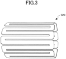
- the heat generating member 120 may have a form as illustrated in FIG. 3 .
- the heat generating member 120 has a configuration in which a conductor in a substantially cylindrical hollow shape is formed with multiple slits along the direction in which the axis of the first heater 100 extends (i.e., the right and left direction of FIG. 3 ).
- the slits are alternately formed from a first direction (for example, the left-hand direction in FIG. 3 ) and a second direction opposite from the first direction (for example, the right-hand direction in FIG. 3 ).
- an insulating core member may be provided in the heat generating member 120.
- the heat generating member 120 can be wound around the core member to form a proper coil shape. Furthermore, with the core member, the coil shape of the heat generating member 120 can be prevented from being deformed.
- the core member is constituted by, for example, ceramics.
- ceramics include oxides, nitrides, and borides of an "Al” element, an "Mg” element, a “Zr” element, a “Y” element, a “Ce” element, a “Be” element, and an "Si” element.
- examples include a compound in which one or more selected from the oxides, the nitrides, and the borides are mixed.
- examples include aluminum oxides, magnesium oxides, zirconium oxides, yttrium oxides, cerium oxides, beryllium oxides, zirconium silicates (zircons), silicon dioxides, mullites, boron nitrides, aluminum nitrides, and the like.
- the core member may be constituted by the same material as the material constituting the intermediate member 140 explained later.
- the core member may be in a tubular or rod shape.
- the electric resistance between the first lead wire 180A and the second lead wire 180B at the room temperature is preferably 0.01 ⁇ or more, and more preferably 0.1 ⁇ or more.
- the electric resistance between the first lead wire 180A and the second lead wire 180B in a temperature range of 1000 degrees Celsius or more is preferably 0.1 ⁇ or more, more preferably 0.5 ⁇ or more, still more preferably 1 ⁇ or more, and yet still more preferably 1.5 ⁇ or more.
- both ends of the heat generating member 120 are bonded to the first lead wire 180A and the second lead wire 180B.
- this bonding is not always necessary, and the first lead wire 180A and the second lead wire 180B may be omitted. Both ends of the heat generating member 120 may extend directly to the outside of the first heater 100.
- the temperature tends to be high at the joint with the heat generating member 120 and in the vicinity thereof. Therefore, instead of directly joining the first lead wire 180A to the heat generating member 120, a conductive heat-resistant material may be interposed between the first lead wire 180A and the heat generating member 120.
- first lead wire 180A and the second lead wire 180B themselves are preferably members (for example, copper) having lower resistivities than the heat generating member 120. In this case, a rise in the temperatures of the first heater end portion 102A and the second heater end portion 102B can be alleviated.
- the respective dimensions with respect to the heat generating member 120 change according to the specification of the first heater 100.
- the outer diameter D 4 of the coil may be in a range of 10 mm to 100 mm.
- the tubular member 130 is constituted by metal as described above.
- the tubular member 130 may be constituted by a material containing at least one selected from, for example, platinum, tungsten, iridium, and molybdenum.
- the tubular member 130 may be constituted by platinum, tungsten, iridium, molybdenum, or alloys thereof.
- the alloy may include platinum and at least one of ruthenium, iridium, gold, and rhodium.
- the tubular member 130 may not be necessarily constituted by a single material, and may be constituted by a combination of two or more types of materials.
- a part where the temperature rises (for example, the second part 105) may be made of the heat-resistant metal as described above, and a part where the temperature does not rise (for example, all or parts of the first part 104 and the third part 106) may be made of stainless steel or nickel-base alloys.
- the tubular member 130 having such a structure can be formed by joining two kinds of materials by, for example, welding or brazing.
- an oxidation resistant coating layer 134 may be provided on all or a part of the first part 104 and/or the third part 106 of the tubular member 130. Such a configuration is particularly preferred when the tubular member 130 is constituted by a metal such as molybdenum or iridium.
- molybdenum exhibits a significant decrease in the oxidation resistance in a temperature range of about 500 degrees Celsius or more
- iridium also exhibits a significant decrease in the oxidation resistance in a temperature range of about 900 degrees Celsius or more. Therefore, depending on the environment in which the first heater 100 is used, atmospheric oxidation may occur in portions of the first part 104 and/or the third part 106 of the tubular member 130 exposed to the atmosphere.
- the coating layer 134 may be; for example, a heat-resistant alloy such as MCrAlY (M is at least one metal selected from Ni, Co, and Fe); a silicide such as MoSi 2 ; platinum; glass; ceramics; or the like.
- MCrAlY M is at least one metal selected from Ni, Co, and Fe
- silicide such as MoSi 2
- platinum platinum
- glass glass
- ceramics or the like.
- the two tips of the tubular member 130 preferably have respective flange portions 139A and 139B as illustrated in Fig. 1 , such as shapes for making flange connections with the first lid member 170A and the second lid member 170B.
- the flange connections of the flange portions 139A and 139B to the first lid member 170A and the second lid member 170B, respectively, allow the internal space 110 to be properly sealed.
- An O-ring such as a heat-resistant rubber and a metallic gasket may be provided between the flange portion 139A (and 139B) and the lid member 170A (and 170B).
- a thickness ((W-D 1 )/2) of the tubular member 130 may be, for example, in a range of 0.3 mm to 10 mm .
- a maximum value (maximum distance) of a gap ((D 1 -D 4 )/2) between the tubular member 130 and the heat generating member is in a range of 0.5 mm to 15 mm, preferably in a range of 1 mm to 9 mm, and still more preferably in a range of 1 mm to 6 mm.
- the intermediate member 140 is constituted by an electrically insulating ceramic.
- the intermediate member 140 is constituted by a material that effectively transmits at least light having a wavelength of from 1 ⁇ m to 2 ⁇ m.
- the transmittance of the intermediate member 140 with respect to light in a range of wavelength of from 1 ⁇ m to 2 ⁇ m is, for example, 50% or more, preferably 60% or more, more preferably 65% or more, and still more preferably 70% or more.
- Examples of materials satisfying such characteristics include sapphire (monocrystalline aluminum oxide), transparent polycrystalline aluminum oxides, aluminum oxynitrides, yttrium oxides, spinel, zirconium oxides, yttrium aluminum garnet, magnesium oxides, quartz, and the like.
- sapphire aluminum oxynitrides, and transparent polycrystalline aluminum oxides are preferable.
- the intermediate member 140 may be constituted by a tube-shaped member of which both ends are open.
- the intermediate member 140 is provided to extend over the second part 105. However, the tip of the intermediate member 140 may extend into the first part 104 and/or the third part 106.
- the intermediate member 140 may be constituted by a single member extending throughout the longitudinal direction, or may be constituted by a combination of multiple members.
- the thickness of the intermediate member 140 i.e., the dimension of (D 2 -D 3 )/2 in FIG. 2 , may be, for example, in a range of 0.5 mm to 5 mm, and preferably in a range of 1 mm to 3 mm.
- a gap (D 1 -D 4 )/2 between the tubular member 130 and the heat generating member 120 may be three times or less, preferably twice or less, of the thickness (D 2 -D 3 )/2 of the intermediate member 140.
- a difference (D 1 -D 4 ) between the inner diameter of the tubular member 130 and the outer diameter of the heat generating member 120 may be three times or less, preferably twice or less, of a difference (D 2 -D 3 ) between the outer diameter and the inner diameter of the intermediate member 140.
- the maximum distance between the intermediate member 140 and the tubular member 130 is preferably twice or less the thickness of the intermediate member, and more preferably equal to or less than the thickness of the intermediate member.
- the maximum distance between the heat generating member 120 and the intermediate member 140 is preferably less than twice the thickness of the intermediate member 140, and more preferably equal to or less than the thickness of the intermediate member 140.
- the volume resistivity of the intermediate member is preferably 10 10 ⁇ m or more, and more preferably 1011 ⁇ m or more, at a room temperature.
- the first insulating member 175A is constituted by an insulating material.
- the first insulating member 175A is required to have a seal function for appropriately sealing the gap between the opening 172A of the first lid member 170A and the first lead wire 180A.
- the insulating member having such as seal function is well known to a person skilled in the art.
- first insulating member 175A and the second insulating member 175B as illustrated in FIG. 1 is merely an example. It is clear to a person skilled in the art that these configurations are not particularly limited as long as the first lead wire 180A and the second lead wire 180B can be properly routed to the outside.
- FIG. 4 schematically illustrates an example of a structure of another heater (hereinafter referred to as a "second heater”) according to the embodiment of the present invention.
- the second heater 200 has a configuration similar to the first heater 100 explained above. Therefore, in FIG. 4 , reference symbols obtained by adding 100 to the reference symbols used in FIG. 1 are given to the members similar to those of the first heater 100.
- the configuration of an intermediate member 240 is different from the intermediate member 140 of the first heater 100.
- the intermediate member 240 is constituted by multiple rings 240a to 240d.
- the rings 240a to 240d are arranged in the internal space 210 of the second heater 200 to surround the heat generating member 220.
- the interval at which the rings 240a to 240d are arranged is not particularly limited. However, the rings are arranged at such intervals that the heat generating member 220 and the tubular member 230 do not come into contact with each other even when the heat generating member 220 is heated to a high temperature to be deformed while the second heater 200 is used.
- the rings 240a to 240d may be arranged at equal (regular) intervals or at unequal (random) intervals along the central axis direction of the second heater 200.
- the widths (i.e., the dimension in the central axis direction of the second heater 200) and the thicknesses (i.e., the dimension in a direction perpendicular to the central axis of the second heater 200) of the rings 240a to 240d may be the same as each other or different from each other.
- the rings 240a to 240d of the second heater 200 do not necessarily have to be constituted by a material that transmits light having a predetermined wavelength. This is because the heat rays generated from the heat generating member 220 can reach the tubular member 230 through the "gaps" between adjacent rings (for example, between the ring 240a and the ring 240b), i.e., through the area where the rings 240a to 240d do not exist. It is to be understood that the rings 240a to 240d may be constituted by a material similar to the intermediate member 140 of the first heater 100 explained above.
- the intermediate member 240 is configured in this way, the effects described above can be obtained. That is, even if the heat generating member 220 is heated to a high temperature, a contact between the heat generating member 220 and the tubular member 230 can be significantly prevented due to the presence of the intermediate member 240.
- the second heater 200 can effectively irradiate the tubular member 230 with the heat rays generated from the heat generating member 220 by the radiation method. As a result, the heat collection efficiency of the tubular member 230 is increased, and the tubular member 230 can be heated to a relatively higher temperature.
- the second heater 200 it is not necessary to use a large-scale device to energize the heat generating member 220, and the size of a system for heating the heating target can be reduced.
- the rings 240a to 240d that constitute the intermediate member 240 are constituted by an insulating material such as a ceramic.
- the intermediate member 240 may be constituted by aluminum oxides, magnesium oxides, zirconium oxides, yttrium oxides, cerium oxides, beryllium oxides, zirconium silicates (zircons), silicon dioxides, mullites, boron nitrides, aluminum nitrides, and the like. Also, the materials applicable to the intermediate member 140 of the first heater 100 described above can also be used.
- the configuration and the arrangement of the rings 240a to 240d are not particularly limited, as long as 50% or more of heat rays radiated from the heat generating member 220 (light having a wavelength of from 1 ⁇ m to 2 pm) can reach the tubular member 230.
- the rings 240a to 240d are constituted by a material that does not transmit heat rays (i.e., the transmittance of the heat rays is zero)
- the rings 240a to 240d are arranged around the heat generating member 220 so that a coverage rate for the heat generating member 220 becomes less than 50%.
- the coverage rate is preferably less than 40%, more preferably less than 35%, and still more preferably less than 30%.
- the number of rings 240a to 240d to be provided is not particularly limited. With respect to the dimensions of the rings 240a to 240d, the explanation about the intermediate member 140 of the first heater 100 can be referred to.
- FIG. 5 schematically illustrates an example of a structure of still another heater (hereinafter referred to as a "third heater") according to the embodiment of the present invention.
- the third heater 300 has a configuration similar to the first heater 100 explained above. Therefore, in FIG. 5 , reference symbols obtained by adding 200 to the reference symbols used in FIG. 1 are given to the members similar to those of the first heater 100.
- the third heater 300 mainly has a difference in that the structure of a second heater end portion 302B is different from the structure of the second heater end portion 102B of the first heater 100.
- the third heater 300 a metal tube of which one end is closed is used as the tubular member 330.
- the members provided in the second heater end portion 102B of the first heater 100 i.e., the second lid member 170B, the second insulating member 175B, and the like) are omitted.
- the second lead wire 380B needs to be routed to the outside through the side of the first heater end portion 302A.
- the heat generating member 320 is configured so that both end portions are guided to the same side. That is, one end portion of the heat generating member 320 passes through the inside of the coil to be guided to the same side as the other end portion.
- the core member having the tubular shape as described above may be used in the heat generating member 320. With the core member, one end portion of the heat generating member 320 can be easily passed through the coil.
- a lid member 370 is used as the first heater end portion 302A of the third heater 300.
- This lid member 370 is provided with a first opening 372A through which the first lead wire 380A is routed to the outside and a second opening 372B through which the second lead wire 380B is routed to the outside.
- the first insulating member 375A is inserted into the first opening 372A of the lid member 370, and the first lead wire 380A penetrates through the first insulating member 375A to be routed to the outside.
- the second insulating member 375B is inserted into the second opening 372B, and the second lead wire 380B penetrates through the second insulating member 375B to be routed to the outside.
- the intermediate member 340 has a tubular shape structure of which both ends are open, like the intermediate member 140 of the first heater 100.
- the intermediate member 340 may be constituted by a tube of which one end (an end on the same side as the second heater end portion 302B) is sealed.
- the third heater 300 can also effectively irradiate the tubular member 330 with the heat rays generated from the heat generating member 320 by the radiation method. As a result, the heat collection efficiency of the tubular member 330 is increased, and the tubular member 330 can be heated to a relatively higher temperature.
- the second heater end portion can be brought into contact with the heating target. Therefore, such a heater can also be used as, for example, a type of heat source that is simply immersed in a melting furnace that melts materials. Such a heater can also be used as a type of heat source that is inserted, in a penetrating manner, from one furnace wall of the melting furnace to the other furnace wall opposite the one wall. Heaters such as the first heater 100 and the second heater 200 in which the lead wires protrude from the respective heater end portions can be used as a type of heat source that is inserted, in a penetrating manner, from one furnace wall of the melting furnace to the other furnace wall opposite the one wall.
- multiple ring-shaped members as illustrated in FIG. 4 may be used as the intermediate member 340 instead of the tubular member.
- various forms can be conceived of as heaters according to the embodiment of the present invention.
- FIG. 6 schematically illustrates an example of configuration of a manufacturing apparatus for manufacturing a glass product (hereinafter referred to as a "first manufacturing apparatus") 500 according to the embodiment of the present invention.
- the first manufacturing apparatus 500 includes a melting unit 510, a conveying unit 520, a forming unit 530, a connection unit 540, and an annealing unit 550.
- the melting unit 510 is a zone for melting a glass material G1 to form molten glass G2.
- the melting unit 510 includes a melting furnace 511 for partitioning a melting chamber 511a. Although not illustrated in the figure, one or more burners may be provided in an upper portion of the melting chamber 511a.
- the conveying unit 520 is a zone for conveying the molten glass G2 formed by the melting unit 510 to the forming unit 530.
- the forming unit 530 is a zone for forming the molten glass G2 carried from the conveying unit 520 into a belt-shaped glass ribbon G3.
- the forming unit 530 includes a forming furnace 531.
- the forming furnace 531 includes a forming chamber 531a for forming the molten glass G2.
- the forming furnace 531 includes a float bath 535 and a ceiling 537 provided in an upper portion of the float bath 535.
- the ceiling 537 is provided with multiple ceiling heaters 539.
- the float bath 535 contains molten metal M.
- the molten metal M is, for example, molten tin and the like. However, in addition to molten tin, a molten tin alloy and the like can also be used.
- the forming chamber 531a is filled with reducing gas.
- the reducing gas is constituted by a mixed gas of hydrogen gas and nitrogen gas.
- the molten glass G2 provided onto the molten metal M is formed into the belt-shaped glass ribbon G3 by using the liquid surface of the molten metal M.
- the glass ribbon G3 gradually solidifies as the glass ribbon G3 flows from the upstream to the downstream of the float bath 535, and is pulled up from the molten metal M at the downstream of the float bath 535.
- the ceiling heaters 539 are provided at intervals along the flow direction of the glass ribbon G3 to adjust the temperature distribution in the flow direction of the glass ribbon G3.
- the ceiling heaters 539 are provided at intervals in the width direction of the glass ribbon G3 to adjust the temperature distribution in the width direction of the glass ribbon G3.
- connection unit 540 is a zone for connecting the forming unit 530 and the annealing unit 550.
- the connection unit 540 includes a connection furnace 541, intermediate heaters 542, and a lift out roll 543.
- connection furnace 541 includes a connection chamber 541a for conveying the glass ribbon G3.
- the multiple intermediate heaters 542 are provided in the connection chamber 541a.
- the intermediate heaters 542 are provided at intervals along the flow direction of the glass ribbon G3 to adjust the temperature distribution in the conveying direction of the glass ribbon G3.
- the intermediate heaters 542 may be divided in the width direction of the glass ribbon G3 to adjust the temperature distribution in the width direction of the glass ribbon G3.
- the lift out roll 543 is rotationally driven by a motor or the like to lift the glass ribbon G3 formed by the forming unit 530 and convey the glass ribbon G3 to the annealing unit 550.
- the annealing unit 550 is a zone for annealing the glass ribbon G3 conveyed from the connection unit 540.
- the annealing unit 550 includes an annealing furnace 551.
- the annealing furnace 551 forms an annealing chamber 551a for annealing the glass ribbon G3.
- the annealing chamber 551a is provided with multiple annealing heaters 552 and multiple annealing rolls 553.
- the annealing chamber 551a is configured so that the temperature gradually decreases from the inlet of the annealing furnace 551 to the outlet of the annealing furnace 551.
- the annealing heaters 552 are provided at intervals along the conveying direction of the glass ribbon G3 to adjust the temperature distribution in the conveying direction of the glass ribbon G3.
- the annealing heaters 552 may be divided in the width direction of the glass ribbon G3 to adjust the temperature distribution in the width direction of the glass ribbon G3.
- the annealing rolls 553 are rotationally driven by a motor or the like to convey the glass ribbon G3 from the entrance of the annealing furnace 551 to the exit of the annealing furnace 551.
- the annealing rolls 553 are provided at intervals along the conveying direction of the glass ribbon G3.
- the melting unit 510 is provided with the heater according to the embodiment of the present invention.
- a heater 580 according to the embodiment of the present invention is provided in the melting furnace 511.
- the heater 580 is illustrated in a simplified manner, and lead wires and the like are not illustrated.
- the heater 580 is arranged horizontally so as to penetrate through the melting furnace 511.
- the heater 580 may be the first or second heater 100, 200 as illustrated in FIG. 1 or FIG. 4 .
- the heater 580 may be the third heater 300 as illustrated in FIG. 5 .
- the heater 580 may be installed vertically by being inserted from the floor below the melting furnace or from above the melting furnace or may be installed horizontally by being inserted from one of the furnace walls.
- multiple heaters 580 are installed.
- the multiple heaters 580 may be installed at intervals at the same height level in the melting furnace 511.
- the multiple heaters 580 may be installed at different height levels in the melting furnace 511.
- the glass material G1 is supplied to the melting unit 510.
- the glass material G1 is supplied to the melting chamber 511a of the melting furnace 511.
- the glass material G1 is melted by heat applied from the heater 580, and the molten glass G2 is formed.
- the heater according to the embodiment of the present invention is used as the heater 580. Therefore, in the melting unit 510, it is not necessary to use a large-scale device, and the size of the melting unit can be reduced.
- the heater 580 can melt, for example, the glass material G1 and heat the molten glass G2 to a high temperature higher than 1500 degrees Celsius.
- the molten glass G2 of the melting unit 510 is supplied to the forming unit 530 via the conveying unit 520.
- the molten glass G2 supplied to the forming unit 530 continuously moves on the molten metal M.
- the belt-shaped glass ribbon G3 is formed from the molten glass G2.
- the glass ribbon G3 gradually solidifies as the glass ribbon G3 flows from upstream to the downstream of the float bath 535.
- the glass ribbon G3 is provided via the connection unit 540 to the annealing unit 550.
- the annealing unit 550 is configured so that the temperature gradually decreases from the upstream to the downstream of the annealing chamber 551a. Accordingly, the temperature of the glass ribbon G3 gradually decreases as the glass ribbon G3 is conveyed in the annealing chamber 551a.
- the glass ribbon G3 is cut into a predetermined size by a cutting machine.
- the manufacturing apparatus for manufacturing a glass product according to the embodiment of the present invention may have other configurations as long as the manufacturing apparatus includes the heater according to the embodiment of the present invention.
- the heater according to the embodiment of the present invention is installed in the melting unit 510.
- the heater according to the embodiment of the present invention may be provided in the conveying unit 520.
- a zone including an additional member such as a refining furnace for removing bubbles contained in the molten glass G2 and/or a stirring furnace for homogenizing the molten glass G2, may be provided between the melting unit 510 and the conveying unit 520.
- the heater according to the embodiment of the present invention may be provided in such a refining furnace and/or such a stirring furnace.
- the conveying unit 520 and the connection unit 540 may be omitted.
- the molten glass G2 formed by the melting unit 510 may be directly discharged to the forming unit 530, and/or the glass ribbon G3 formed by the forming unit 530 may be directly conveyed to the annealing unit 550.
- the method for manufacturing a glass product according to the embodiment of the present invention includes:
- the annealing step is not always a necessary step in the first manufacturing method and may be omitted.
- a glass material is supplied to the melting furnace, in which the glass material is melted.
- the melting furnace may have a configuration similar to the melting furnace 511 of the first manufacturing apparatus 500 explained above.
- the heater according to the embodiment of the present invention may be installed in the melting furnace.
- the glass material is heated by the heater according to the embodiment of the present invention and becomes molten glass.
- the glass material is not particularly limited. However, it should be noted that, in a case where the heater according to the embodiment of the present invention is installed in the melting furnace, the molten glass obtained by melting the glass material can be heated to a high temperature of more than, for example, 1500 degrees Celsius. Specifically, in the first manufacturing method, a glass material having a high melting point can be used.
- the molten glass melted in the melting furnace is conveyed to the forming furnace.
- the molten glass may be discharged from the melting furnace into the conveying unit, and the molten glass may be supplied to the forming furnace from the conveying unit.
- additional apparatus such as a refining furnace may be provided between the melting furnace and the conveying unit.
- the molten glass may be directly provided from the melting furnace to the forming furnace.
- the conveying unit may be provided with the heater according to the embodiment of the present invention.
- the additional apparatus may be provided with the heater according to the embodiment of the present invention.
- the heater according to the embodiment of the present invention may be provided at any position between the melting furnace and the conveying unit.
- the molten glass conveyed to the forming furnace is formed.
- the forming process is not particularly limited.
- the molten glass may be formed by a conventional forming process such as a float process, a downdraw process, a roll out process, or a fusion process.
- the forming unit 530 of the first manufacturing apparatus 500 as illustrated in FIG. 6 may be used.
- a glass ribbon may be formed by providing the molten glass onto the float bath of the forming furnace and conveying the molten glass from the upstream to the downstream.
- the molded glass is cooled to a room temperature. Also, if necessary, the formed glass is cut into a predetermined shape.
- the formed glass product can be manufactured according to the steps described above.
- the heater according to the embodiment of the present invention may be used in any given step between the melting step (step S110) and the forming step (step S120) (however, the any given step does not include the forming step itself).
- the heater according to the embodiment of the present invention is used to heat the molten glass. Therefore, in the first manufacturing method, even if the temperature of the molten glass exceeds a temperature of, for example, 1500 degrees Celsius, the molten glass can be heated stably.
- a heater having a configuration similar to the third heater was made.
- a heating test of a glass melting furnace was carried out with this heater.
- Platinum rhodium alloy was used as the tubular member of the heater.
- the outer diameter W of the tubular member was 30.4 mm, and the inner diameter D 1 was 28.2 mm.
- a sapphire tube was used as the intermediate member.
- the outer diameter D 2 of the sapphire tube was 27.4 mm, and the inner diameter D 3 was 24.4 mm.
- a coiled molybdenum wire with a diameter of 1.0 mm was used as the heat generating member.
- the outer diameter of the heat generating member (diameter D 4 of the coil) was 22.2 mm.
- the resistance value between both of the terminals at a room temperature was about 1.2 ⁇ .
- the lid members on both ends of the heater were constituted by stainless steel. Copper wires were used for the lead wires on both sides.
- the lead wires were electrically connected to the respective end portions of the heat generating member via molybdenum wires having a diameter ⁇ of 1.6 mm.
- the entire length L of the heater was 810 mm.
- the length of the first part of the heater was 280 mm, and the length of the second part was 500 mm.
- the length of the third part 306 of the heater was 30 mm (see FIG. 5 ).
- the glass melting furnace was in a shape of a box with an upper side open and a width of 500 mm. In the side walls of the glass melting furnace, multiple through holes having a diameter of slightly larger than the outer diameter of the heater were formed.
- the heaters were inserted into the respective through holes.
- An outlet for discharging the molten glass was provided in one wall surface parallel to the inserted heater.
- glass scrap was introduced into the glass melting furnace, so that the glass scrap piles up to a position slightly higher than each heater. Therefore, the part of the heater excluding the first heater end part of the heater, i.e., the part of the heater exposed in the melting chamber of the glass melting furnace, was completely covered with glass scraps.
- the glass material was started to be continuously introduced from the upper side of the glass melting furnace.
- the glass material became molten glass in the glass melting furnace and was continuously discharged from the outlet of the glass melting furnace.
- the discharged molten glass was made into a glass product in an approximately plate shape by a roll-out formation process.
- the rate of the introduction of the glass material and the discharge speed of the molten glass were approximately 40 kg/hour in terms of glass.
- Table 1 illustrates a temporal change in the molten glass temperature at the outlet, the voltage, the current, and the power applied to the heater closest to the outlet, the resistance value, and an average temperature of the heat generating members calculated from the resistance value.
- Table 1 Time Heater closest to the outlet Molten glass temperature at outlet °C Voltage V Current A Power kW Resistance value ⁇ Average temperature of heat generating members calculated from the resistance value °C 1/19 03:00 135.7 13.6 1.84 10.0 1671.4 1512.0 1/19 03:30 135.3 13.6 1.84 10.0 1666.7 1509.3 1/19 04:00 135.4 13.6 1.84 10.0 1667.9 1513.5 1/19 04:30 134.8 13.6 1.83 9.9 1659.6 1497.5 1/19 05:00 134.7 13.6 1.83 9.9 1658.4 1486.2 1/19 05:30 134.5 13.7 1.84 9.8 1643.6 1475.5 1/19 06:00 134.5 13.6 1.82 9.9 1656.1 1489.4 1/19 06:30 134.6 13.6 1.83
- the heater used according to the Example functioned stably when the temperature of the heat generating member was 1650 degrees Celsius or more, and the continuously supplied glass material was melted by heating the heater, and that the temperature of the molten glass was raised to 1500 degrees Celsius or more. At that time, the voltage and the current applied to each heater were about 135 V and about 14 A, respectively, which could be achieved by generally-available power supply equipment.
- the heating target can be stably heated without using large-scale power supply facilities by using the heater according to the embodiment of the present invention.
- the present invention relates to the following items:
Landscapes
- Chemical & Material Sciences (AREA)
- Engineering & Computer Science (AREA)
- Materials Engineering (AREA)
- Organic Chemistry (AREA)
- Combustion & Propulsion (AREA)
- Mechanical Engineering (AREA)
- General Engineering & Computer Science (AREA)
- Physics & Mathematics (AREA)
- Thermal Sciences (AREA)
- Resistance Heating (AREA)
Abstract
Description
- The present invention relates to a heater, a manufacturing apparatus for manufacturing a glass product, and a manufacturing method for manufacturing a glass product.
- Conventionally, a heater has been used as a heat source in a melting furnace for melting a metal such as aluminum.
- For example, PTL 1 describes a heater constructed by introducing a coiled heating body and an insulating powder material into a ceramic protection tube. PTL 2 describes a heater constructed by introducing a coiled resistor and a heat-resistant material into a metal sheath. PTL 3 describes an electric device that supplies heat to molten glass by energizing a platinum annular tube.
-
- [PTL 1]
Japanese Unexamined Patent Publication No. 2001-124477 - [PTL 2]
United States Patent Publication No. 4319127 - [PTL 3]
Japanese Examined Patent Publication No. S59-19893 - [PTL 4]
Japanese Translation of PCT Publication No. 2007-529087 - However, conventional heaters described in PTLs 1 and 2 are designed to be used mainly by being immersed in molten metal such as aluminum, and it is difficult to use such heaters upon heating the heaters to a high temperature of 1200 degrees Celsius or more. PTL 4 discloses a heater in which a rod-shaped heating element supported by a supporting ceramic disk is contained within a ceramic pipe. However, this heater is also difficult to be heated to a high temperature of 1200 degrees Celsius or more. PTL 3 describes a heater expected to be used by being immersed in molten glass. However, it is necessary to apply a large current to the heater, and as a result, there arises a problem in that a large-scale power supply device is required. It is stated that a typical voltage and a typical current are 5 V to 6 V and 5000 A, respectively. Therefore, there still is a need for a heater capable of heating to a higher temperature without the need for a large power supply device such as a power supply device that passes a large current of 1000 A or more.
- The present invention has been made in view of such circumstances, and it is an object of the present invention to provide a heater capable of heating to 1200 degrees Celsius or more without the need for a large power supply device. In addition, it is an object of the present invention to provide a manufacturing apparatus having such a heater for manufacturing a glass product and a manufacturing method using such a heater for manufacturing a glass product.
- According to the present invention, provided is a heater including:
- a heat generating member being conductive and configured to radiate heat rays by being fed with electric power;
- a tubular member constituted by a metal and accommodating the heat generating member; and
- an intermediate member arranged between the heat generating member and the tubular member and constituted by an electrically insulating material,
- wherein the intermediate member is arranged and/or configured so as not to block, among the heat rays radiated from the heat generating member, at least light having a wavelength of from 1 µm to 2 µm from reaching the tubular member.
- According to the present invention, provided is a manufacturing apparatus for manufacturing a glass product, including:
- a melting unit configured to melt a glass material to form molten glass; and
- a forming unit configured to make formed glass from the molten glass,
- the manufacturing apparatus further optionally comprising a conveying unit configured to connect the melting unit and the forming unit,
- wherein a heater is provided in any given unit disposed between the melting unit and the forming unit, the any given unit not including the forming unit,
- wherein the heater includes:
- a heat generating member being conductive and configured to radiate heat rays by being fed with electric power;
- a tubular member constituted by a metal and accommodating the heat generating member; and
- an intermediate member provided between the heat generating member and the tubular member and constituted by an electrically insulating material, and
- wherein the intermediate member is arranged and/or configured so as not to block, among the heat rays radiated from the heat generating member, at least light having a wavelength of from 1 µm to 2 µm from reaching the tubular member.
- Further, according to the present invention, provided is a manufacturing method for manufacturing a glass product, including:
- a melting step for melting a glass material to form a molten glass; and
- a forming step for forming the molten glass to make a glass product,
- wherein the molten glass comes into contact with a heater in any given step between the melting step and the forming step, the any given step not including the forming step,
- the heater including:
- a heat generating member being conductive and configured to radiate heat rays by being fed with electric power;
- a tubular member constituted by a metal and accommodating the heat generating member; and
- an intermediate member provided between the heat generating member and the tubular member and constituted by an electrically insulating material, and
- wherein the intermediate member is arranged and/or configured so as not to block, among the heat rays radiated from the heat generating member, at least light having a wavelength of from 1 µm to 2 µm from reaching the tubular member.
- According to the present invention, a heater capable of heating to 1200 degrees Celsius or more without the need for a large power supply device can be provided. In addition, according to the present invention, a manufacturing apparatus having such a heater for manufacturing a glass product and a manufacturing method using such a heater for manufacturing a glass product can be provided.
-
-
FIG. 1 is a drawing schematically illustrating an example of a cross section taken along a central axis of a heater according to an embodiment of the present invention. -
FIG. 2 is a drawing schematically illustrating a cross section taken along line S-S of the heater as illustrated inFIG. 1 . -
FIG. 3 is a drawing schematically illustrating another example of a form of a heat generating member used as a heater according to the embodiment of the present invention. -
FIG. 4 is a drawing schematically illustrating an example of a cross section taken along a central axis of another heater according to the embodiment of the present invention. -
FIG. 5 is a drawing schematically illustrating an example of a cross section taken along a central axis of still another heater according to the embodiment of the present invention. -
FIG. 6 is a cross sectional view schematically illustrating an example of configuration of a manufacturing apparatus for manufacturing a glass product according to an embodiment of the present invention. -
FIG. 7 is a flow diagram schematically illustrating an example of a manufacturing method for manufacturing a glass product according to an embodiment of the present invention. - Hereinafter, an embodiment of the present invention is explained.
- According to the embodiment of the present invention, provided is a heater including:
- a heat generating member being conductive and configured to radiate heat rays by being fed with electric power;
- a tubular member constituted by a metal and accommodating the heat generating member; and
- an intermediate member arranged between the heat generating member and the tubular member and constituted by an electrically insulating material,
- wherein the intermediate member is arranged and/or configured so as not to block, among the heat rays radiated from the heat generating member, at least light having a wavelength of from 1 µm to 2 µm from reaching the tubular member.
- As explained above, there is a problem in conventional heaters when the conventional heaters are used at a high temperature of 1200 degrees Celsius or more.
- The inventors of the present application have earnestly conducted research of heaters in order to address such problems. As a result, the inventors of the present application have discovered that a tubular member (outer tube), which is in contact with the outside (heating target), can be heated to a higher temperature by a radiation heat transfer from the heat generating member than by a conventional method for conducting heat from the heat generating member.
- In a case where a tubular member is heated by a radiation method, it is considered effective not to allow any substance other than gas to exist between the heat generating member and the tubular member. However, in that case, there may be a problem in that the heat generating member is deformed when the heater is used at a high temperature (i.e., when the temperature of the constituent members increases to a high temperature), and the heat generating member and the tubular member come into contact with each other. When such contact occurs in a case where the tubular member is constituted by metal, the supplied current flows toward the tubular member having a lower resistance, and the temperature of the heat generating member does not rise.
- In order to deal with this problem, it may be considered to provide an insulating material between the heat generating member and the tubular member. However, when an insulating material is provided between the heat generating member and the tubular member, the heat rays from the heat generating member are blocked by the insulating material, which makes it difficult to heat the tubular member by the radiation method.
- In contrast, in the heater according to the embodiment of the present invention, an intermediate member is provided between the heat generating member and the tubular member. This intermediate member is arranged and/or configured so as not to block the emission of the heat rays from the heat generating member to the tubular member.
- In order to achieve this, for example, as an intermediate member, a plurality of ring-shaped members may be arranged at intervals on the outer peripheral side of the heat generating member. Alternatively, a single ring-shaped member may be arranged so as to cover only a part of the outer circumference of the heat generating member.
- In addition to this, or separately from this, the intermediate member may be constituted by a material having transparency with respect to the heat rays radiated from the heat generating member. For example, sapphire is known to have a high transmittance (80% or more at a thickness of 1 mm) with respect to light in a range of wavelength from 400 nm to 4000 nm. Aluminum oxynitride is also known to have a high transmittance (80% or more at a thickness of 2 mm) with respect to light in a range of wavelength from 400 nm to 4000 nm.
- With the distinctive configuration as described above, in the heater according to the embodiment of the present invention, the heat rays radiated from the heat generating member can be effectively emitted to the tubular member. Further, even if the heater is heated to a high temperature, a contact between the heat generating member and the tubular member can be significantly prevented due to the presence of the intermediate member.
- Therefore, in the heater according to the embodiment of the present invention, the tubular member can be heated relatively easily to a temperature of 1200 degrees Celsius or more. In addition, in the heater according to the embodiment of the present invention, a material and a shape with a high resistance value can be selected as the heat generating member. In addition, this makes it possible to use a high-voltage and low-current power supply device instead of a conventional low-voltage and high-current large-scale power supply device, and the size of the entire heating system that heats the heating target can be reduced.
- In the embodiment of the present invention, the intermediate member is preferably arranged so as not to block, among the heat rays radiated from the heat generating member, at least light having a wavelength of from 1 µm to 2 µm, for example, light having a wavelength of from 1 µm to 4 pm, from reaching the tubular member.
- An example of configuration of a heater according to an embodiment of the present invention is explained with reference to drawings.
-
FIG. 1 schematically illustrates an example of structure of a heater according to the embodiment of the present invention.FIG. 1 illustrates a cross section taken along a central axis of theheater 100 according to the embodiment of the present invention. However, with respect to theheat generation member 120, which is explained later, a side view is schematically shown, instead of a cross-sectional view, for the sake of clarity. - As illustrated in
FIG. 1 , theheater 100 according to the embodiment of the present invention (hereinafter referred to as a "first heater") has an approximate rod shape extending in a linear manner from a firstheater end portion 102A to a secondheater end portion 102B. - The first
heater end portion 102A is closed by afirst lid member 170A. The secondheater end portion 102B is closed by asecond lid member 170B. Therefore, in thefirst heater 100, aninternal space 110 isolated from the outside is formed. - The
internal space 110 is made into a non-oxidizing gas atmosphere in order to prevent the members contained in theinternal space 110 from oxidizing. For example, theinternal space 110 may be filled with an inert gas such as argon. - However, if a member (for example, a heat generating member described below) accommodated in the
internal space 110 has a resistance against oxidation under the environment in which it is used, it is not always necessary to control the atmosphere in theinternal space 110. In that case, thelid member - The
first heater 100 includes aheat generating member 120, atubular member 130, and anintermediate member 140. - The
heat generating member 120 and theintermediate member 140 are accommodated in theinternal space 110. Thetubular member 130, as well as thefirst lid member 170A and thesecond lid member 170B explained above, are members for dividing theinternal space 110 of thefirst heater 100. Thetubular member 130 protects the members accommodated in theinternal space 110. Thetubular member 130 is constituted by metal. - The
heat generating member 120 functions as a heating body that generates heat when it is energized. Theheat generating member 120 is constituted by a conductive material such as metal. One of the end portions of theheat generating member 120 is electrically connected to thefirst lead wire 180A. The other of the end portions of theheat generating member 120 is electrically connected to asecond lead wire 180B. - The
first lead wire 180A extends to the outside of theinternal space 110 through afirst opening 172A provided in thefirst lid member 170A. Likewise, thesecond lead wire 180B extends to the outside of theinternal space 110 through asecond opening 172B provided in thesecond lid member 170B. In order to prevent thefirst lead wire 180A from coming into contact with thefirst lid member 170A, a first insulatingmember 175A is attached to thefirst opening 172A of thefirst lid member 170A. Likewise, a second insulatingmember 175B is attached to thesecond opening 172B of thesecond lid member 170B. - For example, in particular cases, such as in a case where the
first lead wire 180A and theheat generating member 120 are constituted by the same material, the boundary between thefirst lead wire 180A and theheat generating member 120 may be ambiguous. The same applies to the relationship between thesecond lead wire 180B and theheat generating member 120. - Therefore, in the present application, the
first lead wire 180A or thesecond lead wire 180B is defined as a portion exposed to a temperature of 400 degrees Celsius or less at the maximum during normal use. This enables distinguishing thefirst lead wire 180A or thesecond lead wire 180B from theheat generating member 120. - In the example as illustrated in
FIG. 1 , theheat generating member 120 has an approximate coiled form in order to increase the amount of heat generated per unit area and increase the resistance value. However, this is merely an example, and theheat generating member 120 does not necessarily have to have a coiled form. - The
intermediate member 140 is arranged between thetubular member 130 and theheat generating member 120. Theintermediate member 140 is constituted by an electrically insulating material. - In the example as illustrated in
FIG. 1 , theintermediate member 140 has an approximate tube-shaped structure with both ends open. Therefore, theheat generating member 120 has been introduced into the inside of theintermediate member 140. Theintermediate member 140 is constituted by a ceramic material having a transmittance of 50% or more with respect to at least light having a wavelength of from 1 µm to 2 µm. - The
intermediate member 140 may be constituted by a ceramic material having a transmittance of 50% or more with respect to the light having the wavelength of from 1 µm to 2 pm, for example, light having a wavelength of from 1 µm to 4 µm. - Hereinafter, an operation of the
first heater 100 having such a configuration is explained. - When the
first heater 100 is used, thefirst heater 100 is installed in or in proximity to the heating target. Also, a power supply device (not illustrated) is used to supply a current to thefirst lead wire 180A and thesecond lead wire 180B. - With the supplied electric current, the
heat generating member 120 connected to thefirst lead wire 180A and thesecond lead wire 180B is resistance-heated. Also, this causes heat rays to be radiated from theheat generating member 120. The heat rays have a wavelength in a range of visible light to infrared (for example 400 nm to 5 pm). - First, the heat rays radiated from the
heat generating member 120 are emitted to theintermediate member 140. - In this case, as described above, the
intermediate member 140 is constituted by a ceramic material having a transparency with respect to light having the wavelength of from 1 µm to 2 um. Therefore, at least some of heat rays (i.e., heat rays having a wavelength of from 1 µm to 2 pm) can pass through theintermediate member 140. - Thereafter, the heat rays having passed through the
intermediate member 140 are emitted onto thetubular member 130. Accordingly, the temperature of thetubular member 130 rises. Also, due to this rise in the temperature, the heating target in contact with the outer surface of thetubular member 130 is heated. - In this manner, the heating target can be heated by using the
first heater 100. - Because the
first heater 100 has theintermediate member 140, thefirst heater 100 can significantly prevent electrical contact between theheat generating member 120 and thetubular member 130 even when the temperature of theheat generating member 120 rises while thefirst heater 100 is used. - In addition, with the
first heater 100, thetubular member 130 can be effectively irradiated with the heat rays generated from theheat generating member 120 by the radiation method. As a result, the heat collection efficiency of thetubular member 130 is increased, and the heating target can be heated to a relatively higher temperature. For example, in thefirst heater 100, thetubular member 130 can be stably heated to 1200 degrees Celsius or more, for example, to 1400 degrees Celsius or more or to 1500 degrees Celsius or more. - In addition, with the
first heater 100, it is not necessary to use a large-scale device to energize theheat generating member 120, and the size of a system for heating the heating target can be reduced. - Hereinafter, the components included in the heater according to the embodiment of the present invention is explained in more details. In this case, for the sake of clarity, the components are explained with reference to the
first heater 100, for example. Therefore, when the members are referred to, reference symbols illustrated inFIG. 1 are used. - The shape of the
first heater 100 is not particularly limited. Thefirst heater 100 may have, for example, a substantially cylindrical or substantially prismatic form. The cross section of thefirst heater 100 perpendicular to the longitudinal direction (i.e., the direction of the central axis) may be a substantially circular shape, a substantially elliptical shape, a substantially triangular shape, a substantially quadrangular shape (including trapezoids), or any other polygonal shape. - In the following description, for example, it is assumed that the cross section of the
first heater 100 is a substantially circular shape. - Also, for the sake of clarifying the explanation, as illustrated in
FIG. 1 , thefirst heater 100 is divided into three parts along the longitudinal direction, i.e., afirst part 104, asecond part 105, and athird part 106, for the sake of convenience. - Among them, where the end of the first
heater end portion 102A of thefirst heater 100 is defined as a position at a distance 0 (zero), thefirst part 104 represents a zone between the position at thedistance 0 and a position at a predetermined distance (X1) away from the position at thedistance 0 toward the secondheater end portion 102B. - Also, the
second part 105 represents a zone between the position at the distance X1 and a position at a predetermined distance (X2) away from the position at thedistance 0 toward the secondheater end portion 102B. Therefore, the length of thesecond part 105 is X2-X1. - The
third part 106 represents a zone between the position at the distance X2 and the secondheater end portion 102B. Therefore, the length of thethird part 106 is L-X2. In this case, L denotes the entire length of the first heater 100 (specifically, the outer surface of thefirst lid member 170A to the outer surface of thesecond lid member 170B; seeFIG. 1 ) . - In this case, the
second part 105 includes the part where the temperature rises most greatly while thefirst heater 100 is used. Normally, thefirst heater 100 reaches the highest temperature at an approximate center of thesecond part 105, i.e., a position at L/2 (=X1+ (X2-X1)/2=X1/2+X2/2) with respect to the position at thedistance 0. - In contrast, the
first part 104 and thethird part 106 include parts where the temperatures do not rise greatly while thefirst heater 100 is used. In other words, normally, while thefirst heater 100 is used, the temperature of thefirst part 104 becomes the highest at the position of X1, and tends to gradually decrease toward the position at thedistance 0. In thethird part 106, the temperature tends to change in a similar manner. - In the
first heater 100, the length (X1) of thefirst part 104, the length (X2-X1) of thesecond part 105, and the length (L-X2) of thethird part 106 change according to the entire length L, the specification, and the like of thefirst heater 100. - In the present application, for the sake of convenience, a portion around the connection portion between the
heat generating member 120 and thefirst lead wire 180A is defined as a boundary between thefirst part 104 and thesecond part 105, and a portion around the connection portion between theheat generating member 120 and thesecond lead wire 180B is defined as a boundary between thesecond part 105 and thethird part 106. However, such definitions are merely examples, and it should be noted that a boundary between parts may be defined on the basis of other criteria. For example, both ends of theintermediate member 140 may be defined as the boundary between thefirst part 104 and thesecond part 105 and a boundary between thesecond part 105 and thethird part 106, respectively. - Hereinafter, each member constituting the
first heater 100 is explained in details. -
FIG. 2 schematically illustrates an example of a cross section taken along line S-S of thefirst heater 100 illustrated inFIG. 1 . As described above, it is assumed that the cross section of thefirst heater 100 is a substantially circular shape. - In
FIG. 2 , W denotes a diameter of the first heater 100 (i.e., the outer diameter of the tubular member 130). D1 denotes an inner diameter of thetubular member 130. D2 denotes an outer diameter of theintermediate member 140. D3 denotes an inner diameter of theintermediate member 140. D4 denotes an outer diameter of the heat generating member 120 (coil). - Hereinafter, the symbols illustrated in
FIG. 2 are used to indicate the dimensions of the respective members in the cross section. - The
internal space 110 where various members are accommodated preferably has a low oxygen partial pressure. - For this reason, the
internal space 110 may be filled with a non-oxidizing gas such as a reducing gas and/or an inert gas. Hydrogen can be used as the reducing gas. As the inert gas, one or more selected from argon, helium, neon, krypton, xenon, radon, and nitrogen can be used. - In addition to this, or separately from this, the
internal space 110 may be adjusted to be substantially at the atmospheric pressure while thefirst heater 100 is used. - In order to achieve such a non-oxidizing environment and/or an atmospheric pressure environment during use, one or two ports in communication with the
internal space 110 may be provided in at least one of thefirst lid member 170A and thesecond lid member 170B. Through these ports, theinternal space 110 can be filled with gas and the gas can be exhausted from theinternal space 110. Through these ports, theinternal space 110 can be filled with gas and the gas can be discharged from theinternal space 110. - The configurations of the
first lid member 170A and thesecond lid member 170B are not particularly limited as long as the environment of theinternal space 110 can be properly maintained. Therefore, the description about thefirst lid member 170A and thesecond lid member 170B is omitted here. - The
heat generating member 120 is constituted by a conductive material having heat-resistance. Theheat generating member 120 may be constituted by a material containing at least one selected from, for example, molybdenum, tungsten, tantalum, niobium, iridium, platinum, and rhodium. Specifically, theheat generating member 120 may be constituted by a metal such as molybdenum, tungsten, tantalum, niobium, iridium, platinum, and rhodium or an alloy including at least one of such metals (hereinafter metals and alloys are collectively referred to as "metals"). In particular, theheat generating member 120 is preferably constituted by a metal that can withstand a high temperature of 1800 degrees Celsius. Alternatively, theheat generating member 120 may be made using a resistance heat generating member made of an intermetallic compound or a non-metal, such as molybdenum disilicide (MoSi2), silicon carbide (SiC), lanthanum chromite (LaCrO3), or carbon (C) . - In this case, it should be noted that the
heat generating member 120 does not necessarily have to be constituted by the same material and/or made to have the same shape over the entire length. In other words, theheat generating member 120 may have multiple materials and/or multiple shapes over the entire length. - For example, the
heat generating member 120 may be configured to have a first material in a first segment, a second material in a second segment, ... and an n-th material in an n-th segment. In this case, n denotes an integer of 2 or more. Also, theheat generating member 120 may be configured to have a first form in a first segment, a second form in a second segment, ... and an n-th form in an n-th segment. In this case, n denotes an integer of 2 or more. - When the
heat generating member 120 has multiple segments in this manner, temperature changes can be intentionally made over the entire length. - For example, in a case where the first segment is made of a material of which resistance is higher than a second segment, the temperature of the first segment can be set to a higher temperature than the second segment, even in a case where the
heat generating member 120 is energized with the same current value. Likewise, in a case where the first segment is made into a form having a resistance value per unit length higher than the second segment, the temperature of the first segment can be set to a higher temperature than the second segment. - When the
first heater 100 is used, theheat generating member 120 can attain a temperature of 1500 degrees Celsius or more or 1600 degrees Celsius or more. - The form of the
heat generating member 120 is not particularly limited. Theheat generating member 120 may be constituted by, for example, a coiled linear member as illustrated inFIG. 1 . Alternatively, theheat generating member 120 may have a rod shape (i.e., a solid shape), a plate shape, a tubular shape (i.e., a hollow shape), or the like. Still alternatively, theheat generating member 120 may have a shape with a combination of two or more selected from a coiled part, a rod-shaped part, a plate-shaped part, and a tube-shaped part. Still yet alternatively, multipleheat generating members 120 may be provided. In this case, the radius of the circumscribed circle that can surround a bundle of the multipleheat generating members 120 is defined as the outer diameter D4 of theheat generating members 120. - Also, the
heat generating member 120 may have a form as illustrated inFIG. 3 . - In the example as illustrated in
FIG. 3 , theheat generating member 120 has a configuration in which a conductor in a substantially cylindrical hollow shape is formed with multiple slits along the direction in which the axis of thefirst heater 100 extends (i.e., the right and left direction ofFIG. 3 ). The slits are alternately formed from a first direction (for example, the left-hand direction inFIG. 3 ) and a second direction opposite from the first direction (for example, the right-hand direction inFIG. 3 ). - In a case where the
heat generating member 120 is coiled, an insulating core member may be provided in theheat generating member 120. With the core member, theheat generating member 120 can be wound around the core member to form a proper coil shape. Furthermore, with the core member, the coil shape of theheat generating member 120 can be prevented from being deformed. - The core member is constituted by, for example, ceramics. Examples of such ceramics include oxides, nitrides, and borides of an "Al" element, an "Mg" element, a "Zr" element, a "Y" element, a "Ce" element, a "Be" element, and an "Si" element. Also, examples include a compound in which one or more selected from the oxides, the nitrides, and the borides are mixed. Specifically, examples include aluminum oxides, magnesium oxides, zirconium oxides, yttrium oxides, cerium oxides, beryllium oxides, zirconium silicates (zircons), silicon dioxides, mullites, boron nitrides, aluminum nitrides, and the like. Also, the core member may be constituted by the same material as the material constituting the
intermediate member 140 explained later. - For example, the core member may be in a tubular or rod shape.
- In the
heat generating member 120, the electric resistance between thefirst lead wire 180A and thesecond lead wire 180B at the room temperature is preferably 0.01 Ω or more, and more preferably 0.1 Ω or more. The electric resistance between thefirst lead wire 180A and thesecond lead wire 180B in a temperature range of 1000 degrees Celsius or more is preferably 0.1 Ω or more, more preferably 0.5 Ω or more, still more preferably 1 Ω or more, and yet still more preferably 1.5 Ω or more. - In the example as illustrated in
FIG. 1 , both ends of theheat generating member 120 are bonded to thefirst lead wire 180A and thesecond lead wire 180B. However, this bonding is not always necessary, and thefirst lead wire 180A and thesecond lead wire 180B may be omitted. Both ends of theheat generating member 120 may extend directly to the outside of thefirst heater 100. - Moreover, in the
first lead wire 180A and thesecond lead wire 180B, the temperature tends to be high at the joint with theheat generating member 120 and in the vicinity thereof. Therefore, instead of directly joining thefirst lead wire 180A to theheat generating member 120, a conductive heat-resistant material may be interposed between thefirst lead wire 180A and theheat generating member 120. - Conversely, the
first lead wire 180A and thesecond lead wire 180B themselves are preferably members (for example, copper) having lower resistivities than theheat generating member 120. In this case, a rise in the temperatures of the firstheater end portion 102A and the secondheater end portion 102B can be alleviated. - The respective dimensions with respect to the
heat generating member 120 change according to the specification of thefirst heater 100. As merely an example, if theheat generating member 120 is coiled, the outer diameter D4 of the coil may be in a range of 10 mm to 100 mm. - The
tubular member 130 is constituted by metal as described above. Thetubular member 130 may be constituted by a material containing at least one selected from, for example, platinum, tungsten, iridium, and molybdenum. Specifically, thetubular member 130 may be constituted by platinum, tungsten, iridium, molybdenum, or alloys thereof. When a platinum alloy is used as thetubular member 130, the alloy may include platinum and at least one of ruthenium, iridium, gold, and rhodium. - The
tubular member 130 may not be necessarily constituted by a single material, and may be constituted by a combination of two or more types of materials. For example, in thetubular member 130, a part where the temperature rises (for example, the second part 105) may be made of the heat-resistant metal as described above, and a part where the temperature does not rise (for example, all or parts of thefirst part 104 and the third part 106) may be made of stainless steel or nickel-base alloys. Thetubular member 130 having such a structure can be formed by joining two kinds of materials by, for example, welding or brazing. - It should be noted that an oxidation
resistant coating layer 134 may be provided on all or a part of thefirst part 104 and/or thethird part 106 of thetubular member 130. Such a configuration is particularly preferred when thetubular member 130 is constituted by a metal such as molybdenum or iridium. - Generally, molybdenum exhibits a significant decrease in the oxidation resistance in a temperature range of about 500 degrees Celsius or more, and iridium also exhibits a significant decrease in the oxidation resistance in a temperature range of about 900 degrees Celsius or more. Therefore, depending on the environment in which the
first heater 100 is used, atmospheric oxidation may occur in portions of thefirst part 104 and/or thethird part 106 of thetubular member 130 exposed to the atmosphere. - However, when the
coating layer 134 is provided, such atmospheric oxidation can be reduced. - It should be noted that a portion corresponding to the
tubular member 130 corresponding to thesecond part 105 is in contact with the heating target, which is not the atmospheric air, while thefirst heater 100 is used. Therefore, in such a portion, the risk of atmospheric oxidation is low. For this reason, it is not necessary to provide thecoating layer 134 in such a portion. - The
coating layer 134 may be; for example, a heat-resistant alloy such as MCrAlY (M is at least one metal selected from Ni, Co, and Fe); a silicide such as MoSi2; platinum; glass; ceramics; or the like. - The two tips of the
tubular member 130 preferably haverespective flange portions Fig. 1 , such as shapes for making flange connections with thefirst lid member 170A and thesecond lid member 170B. The flange connections of theflange portions first lid member 170A and thesecond lid member 170B, respectively, allow theinternal space 110 to be properly sealed. - An O-ring such as a heat-resistant rubber and a metallic gasket may be provided between the
flange portion 139A (and 139B) and thelid member 170A (and 170B). - A thickness ((W-D1)/2) of the
tubular member 130 may be, for example, in a range of 0.3 mm to 10 mm . - For example, a maximum value (maximum distance) of a gap ((D1-D4)/2) between the
tubular member 130 and the heat generating member is in a range of 0.5 mm to 15 mm, preferably in a range of 1 mm to 9 mm, and still more preferably in a range of 1 mm to 6 mm. - As described above, the
intermediate member 140 is constituted by an electrically insulating ceramic. Theintermediate member 140 is constituted by a material that effectively transmits at least light having a wavelength of from 1 µm to 2 µm. - The transmittance of the
intermediate member 140 with respect to light in a range of wavelength of from 1 µm to 2 µm is, for example, 50% or more, preferably 60% or more, more preferably 65% or more, and still more preferably 70% or more. - Examples of materials satisfying such characteristics include sapphire (monocrystalline aluminum oxide), transparent polycrystalline aluminum oxides, aluminum oxynitrides, yttrium oxides, spinel, zirconium oxides, yttrium aluminum garnet, magnesium oxides, quartz, and the like.
- In particular, sapphire, aluminum oxynitrides, and transparent polycrystalline aluminum oxides are preferable.
- For example, the
intermediate member 140 may be constituted by a tube-shaped member of which both ends are open. - The
intermediate member 140 is provided to extend over thesecond part 105. However, the tip of theintermediate member 140 may extend into thefirst part 104 and/or thethird part 106. - The
intermediate member 140 may be constituted by a single member extending throughout the longitudinal direction, or may be constituted by a combination of multiple members. - The thickness of the
intermediate member 140, i.e., the dimension of (D2-D3)/2 inFIG. 2 , may be, for example, in a range of 0.5 mm to 5 mm, and preferably in a range of 1 mm to 3 mm. - A gap (D1-D4)/2 between the
tubular member 130 and theheat generating member 120 may be three times or less, preferably twice or less, of the thickness (D2-D3)/2 of theintermediate member 140. - In a case where a thickness deviation of the
intermediate member 140 is large, a difference (D1-D4) between the inner diameter of thetubular member 130 and the outer diameter of theheat generating member 120 may be three times or less, preferably twice or less, of a difference (D2-D3) between the outer diameter and the inner diameter of theintermediate member 140. - The maximum distance between the
intermediate member 140 and thetubular member 130 is preferably twice or less the thickness of the intermediate member, and more preferably equal to or less than the thickness of the intermediate member. The maximum distance between theheat generating member 120 and theintermediate member 140 is preferably less than twice the thickness of theintermediate member 140, and more preferably equal to or less than the thickness of theintermediate member 140. - The volume resistivity of the intermediate member is preferably 1010 Ωm or more, and more preferably 1011 Ωm or more, at a room temperature.
- The first insulating
member 175A is constituted by an insulating material. In addition, the first insulatingmember 175A is required to have a seal function for appropriately sealing the gap between theopening 172A of thefirst lid member 170A and thefirst lead wire 180A. - The insulating member having such as seal function is well known to a person skilled in the art.
- The same can be said with respect to the second insulating
member 175B. - It should be noted that the configuration of the first insulating
member 175A and the second insulatingmember 175B as illustrated inFIG. 1 is merely an example. It is clear to a person skilled in the art that these configurations are not particularly limited as long as thefirst lead wire 180A and thesecond lead wire 180B can be properly routed to the outside. - Hereinafter, an example of configuration of another heater according to the embodiment of the present invention is explained with reference to
FIG. 4 . -
FIG. 4 schematically illustrates an example of a structure of another heater (hereinafter referred to as a "second heater") according to the embodiment of the present invention. - As illustrated in
FIG. 4 , thesecond heater 200 has a configuration similar to thefirst heater 100 explained above. Therefore, inFIG. 4 , reference symbols obtained by adding 100 to the reference symbols used inFIG. 1 are given to the members similar to those of thefirst heater 100. - However, in the
second heater 200, the configuration of anintermediate member 240 is different from theintermediate member 140 of thefirst heater 100. - Specifically, in the
second heater 200, theintermediate member 240 is constituted bymultiple rings 240a to 240d. - The
rings 240a to 240d are arranged in theinternal space 210 of thesecond heater 200 to surround theheat generating member 220. - The interval at which the
rings 240a to 240d are arranged is not particularly limited. However, the rings are arranged at such intervals that theheat generating member 220 and thetubular member 230 do not come into contact with each other even when theheat generating member 220 is heated to a high temperature to be deformed while thesecond heater 200 is used. - The
rings 240a to 240d may be arranged at equal (regular) intervals or at unequal (random) intervals along the central axis direction of thesecond heater 200. - Also, the widths (i.e., the dimension in the central axis direction of the second heater 200) and the thicknesses (i.e., the dimension in a direction perpendicular to the central axis of the second heater 200) of the
rings 240a to 240d may be the same as each other or different from each other. - Unlike the
intermediate member 140 of thefirst heater 100, therings 240a to 240d of thesecond heater 200 do not necessarily have to be constituted by a material that transmits light having a predetermined wavelength. This is because the heat rays generated from theheat generating member 220 can reach thetubular member 230 through the "gaps" between adjacent rings (for example, between thering 240a and thering 240b), i.e., through the area where therings 240a to 240d do not exist. It is to be understood that therings 240a to 240d may be constituted by a material similar to theintermediate member 140 of thefirst heater 100 explained above. - Even in a case where the
intermediate member 240 is configured in this way, the effects described above can be obtained. That is, even if theheat generating member 220 is heated to a high temperature, a contact between theheat generating member 220 and thetubular member 230 can be significantly prevented due to the presence of theintermediate member 240. - In addition, the
second heater 200 can effectively irradiate thetubular member 230 with the heat rays generated from theheat generating member 220 by the radiation method. As a result, the heat collection efficiency of thetubular member 230 is increased, and thetubular member 230 can be heated to a relatively higher temperature. - In addition, with the
second heater 200, it is not necessary to use a large-scale device to energize theheat generating member 220, and the size of a system for heating the heating target can be reduced. - For the specifications of most of the components included in the
second heater 200, the above description can be referred to. Therefore, hereinafter, the features of theintermediate member 240 of thesecond heater 200 are explained in detail. - The
rings 240a to 240d that constitute theintermediate member 240 are constituted by an insulating material such as a ceramic. - For example, the
intermediate member 240 may be constituted by aluminum oxides, magnesium oxides, zirconium oxides, yttrium oxides, cerium oxides, beryllium oxides, zirconium silicates (zircons), silicon dioxides, mullites, boron nitrides, aluminum nitrides, and the like. Also, the materials applicable to theintermediate member 140 of thefirst heater 100 described above can also be used. - Herein, the configuration and the arrangement of the
rings 240a to 240d are not particularly limited, as long as 50% or more of heat rays radiated from the heat generating member 220 (light having a wavelength of from 1 µm to 2 pm) can reach thetubular member 230. - For example, in a case where the
rings 240a to 240d are constituted by a material that does not transmit heat rays (i.e., the transmittance of the heat rays is zero), therings 240a to 240d are arranged around theheat generating member 220 so that a coverage rate for theheat generating member 220 becomes less than 50%. The coverage rate is preferably less than 40%, more preferably less than 35%, and still more preferably less than 30%. - The number of
rings 240a to 240d to be provided is not particularly limited. With respect to the dimensions of therings 240a to 240d, the explanation about theintermediate member 140 of thefirst heater 100 can be referred to. - Hereinafter, an example of configuration of still another heater according to the embodiment of the present invention is explained with reference to
FIG. 5 . -
FIG. 5 schematically illustrates an example of a structure of still another heater (hereinafter referred to as a "third heater") according to the embodiment of the present invention. - As illustrated in
FIG. 5 , thethird heater 300 has a configuration similar to thefirst heater 100 explained above. Therefore, inFIG. 5 , reference symbols obtained by adding 200 to the reference symbols used inFIG. 1 are given to the members similar to those of thefirst heater 100. - However, the
third heater 300 mainly has a difference in that the structure of a secondheater end portion 302B is different from the structure of the secondheater end portion 102B of thefirst heater 100. - That is, in the
third heater 300, a metal tube of which one end is closed is used as thetubular member 330. As a result, in thethird heater 300, the members provided in the secondheater end portion 102B of the first heater 100 (i.e., thesecond lid member 170B, the second insulatingmember 175B, and the like) are omitted. - However, in the
third heater 300, thesecond lead wire 380B needs to be routed to the outside through the side of the firstheater end portion 302A. - Therefore, the
heat generating member 320 is configured so that both end portions are guided to the same side. That is, one end portion of theheat generating member 320 passes through the inside of the coil to be guided to the same side as the other end portion. In this case, the core member having the tubular shape as described above may be used in theheat generating member 320. With the core member, one end portion of theheat generating member 320 can be easily passed through the coil. - Also, a
lid member 370 is used as the firstheater end portion 302A of thethird heater 300. - This
lid member 370 is provided with afirst opening 372A through which thefirst lead wire 380A is routed to the outside and asecond opening 372B through which thesecond lead wire 380B is routed to the outside. The first insulatingmember 375A is inserted into thefirst opening 372A of thelid member 370, and thefirst lead wire 380A penetrates through the first insulatingmember 375A to be routed to the outside. The second insulatingmember 375B is inserted into thesecond opening 372B, and thesecond lead wire 380B penetrates through the second insulatingmember 375B to be routed to the outside. - In addition, in the example illustrated in
FIG. 5 , theintermediate member 340 has a tubular shape structure of which both ends are open, like theintermediate member 140 of thefirst heater 100. Alternatively, in thethird heater 300, theintermediate member 340 may be constituted by a tube of which one end (an end on the same side as the secondheater end portion 302B) is sealed. - It is clear that the above-mentioned effects can also be obtained with the
third heater 300. That is, thethird heater 300 can also effectively irradiate thetubular member 330 with the heat rays generated from theheat generating member 320 by the radiation method. As a result, the heat collection efficiency of thetubular member 330 is increased, and thetubular member 330 can be heated to a relatively higher temperature. - In addition, it is not necessary to use a large-scale device to energize the
heat generating member 320, and the size of a system for heating the heating target can be reduced. - In such a heater as illustrated in
FIG. 5 in which the lead wires are gathered at one end, the second heater end portion can be brought into contact with the heating target. Therefore, such a heater can also be used as, for example, a type of heat source that is simply immersed in a melting furnace that melts materials. Such a heater can also be used as a type of heat source that is inserted, in a penetrating manner, from one furnace wall of the melting furnace to the other furnace wall opposite the one wall. Heaters such as thefirst heater 100 and thesecond heater 200 in which the lead wires protrude from the respective heater end portions can be used as a type of heat source that is inserted, in a penetrating manner, from one furnace wall of the melting furnace to the other furnace wall opposite the one wall. - Hereinabove, the configuration and features of the heater according to the embodiment of the present invention have been described with reference to the
first heater 100 to thethird heater 300. However, it should be noted that this is merely an example, and a person skilled in the art can conceive of various configurations of heaters by referring to the above explanation. - For example, in the
third heater 300 illustrated inFIG. 5 , multiple ring-shaped members as illustrated inFIG. 4 may be used as theintermediate member 340 instead of the tubular member. In addition, various forms can be conceived of as heaters according to the embodiment of the present invention. - Hereinafter, a configuration of a manufacturing apparatus for manufacturing a glass product according to the embodiment of the present invention is explained with reference to
FIG. 6 . -
FIG. 6 schematically illustrates an example of configuration of a manufacturing apparatus for manufacturing a glass product (hereinafter referred to as a "first manufacturing apparatus") 500 according to the embodiment of the present invention. - As illustrated in
FIG. 6 , thefirst manufacturing apparatus 500 includes amelting unit 510, a conveyingunit 520, a formingunit 530, aconnection unit 540, and anannealing unit 550. - The
melting unit 510 is a zone for melting a glass material G1 to form molten glass G2. - The
melting unit 510 includes amelting furnace 511 for partitioning amelting chamber 511a. Although not illustrated in the figure, one or more burners may be provided in an upper portion of themelting chamber 511a. - The conveying
unit 520 is a zone for conveying the molten glass G2 formed by themelting unit 510 to the formingunit 530. - The forming
unit 530 is a zone for forming the molten glass G2 carried from the conveyingunit 520 into a belt-shaped glass ribbon G3. - The forming
unit 530 includes a formingfurnace 531. The formingfurnace 531 includes a formingchamber 531a for forming the molten glass G2. The formingfurnace 531 includes afloat bath 535 and aceiling 537 provided in an upper portion of thefloat bath 535. Theceiling 537 is provided withmultiple ceiling heaters 539. - The
float bath 535 contains molten metal M. The molten metal M is, for example, molten tin and the like. However, in addition to molten tin, a molten tin alloy and the like can also be used. - In order to suppress the oxidation of the molten metal M, the forming
chamber 531a is filled with reducing gas. For example, the reducing gas is constituted by a mixed gas of hydrogen gas and nitrogen gas. - In the
float bath 535, the molten glass G2 provided onto the molten metal M is formed into the belt-shaped glass ribbon G3 by using the liquid surface of the molten metal M. - The glass ribbon G3 gradually solidifies as the glass ribbon G3 flows from the upstream to the downstream of the
float bath 535, and is pulled up from the molten metal M at the downstream of thefloat bath 535. - The
ceiling heaters 539 are provided at intervals along the flow direction of the glass ribbon G3 to adjust the temperature distribution in the flow direction of the glass ribbon G3. Theceiling heaters 539 are provided at intervals in the width direction of the glass ribbon G3 to adjust the temperature distribution in the width direction of the glass ribbon G3. - The
connection unit 540 is a zone for connecting the formingunit 530 and theannealing unit 550. Theconnection unit 540 includes aconnection furnace 541,intermediate heaters 542, and a lift outroll 543. - The
connection furnace 541 includes aconnection chamber 541a for conveying the glass ribbon G3. The multipleintermediate heaters 542 are provided in theconnection chamber 541a. - The
intermediate heaters 542 are provided at intervals along the flow direction of the glass ribbon G3 to adjust the temperature distribution in the conveying direction of the glass ribbon G3. Theintermediate heaters 542 may be divided in the width direction of the glass ribbon G3 to adjust the temperature distribution in the width direction of the glass ribbon G3. - The lift out
roll 543 is rotationally driven by a motor or the like to lift the glass ribbon G3 formed by the formingunit 530 and convey the glass ribbon G3 to theannealing unit 550. - The
annealing unit 550 is a zone for annealing the glass ribbon G3 conveyed from theconnection unit 540. - The
annealing unit 550 includes anannealing furnace 551. Theannealing furnace 551 forms anannealing chamber 551a for annealing the glass ribbon G3. Theannealing chamber 551a is provided withmultiple annealing heaters 552 and multiple annealing rolls 553. Theannealing chamber 551a is configured so that the temperature gradually decreases from the inlet of theannealing furnace 551 to the outlet of theannealing furnace 551. - The annealing
heaters 552 are provided at intervals along the conveying direction of the glass ribbon G3 to adjust the temperature distribution in the conveying direction of the glass ribbon G3. The annealingheaters 552 may be divided in the width direction of the glass ribbon G3 to adjust the temperature distribution in the width direction of the glass ribbon G3. - The annealing rolls 553 are rotationally driven by a motor or the like to convey the glass ribbon G3 from the entrance of the
annealing furnace 551 to the exit of theannealing furnace 551. The annealing rolls 553 are provided at intervals along the conveying direction of the glass ribbon G3. - Herein, in the
first manufacturing apparatus 500, themelting unit 510 is provided with the heater according to the embodiment of the present invention. - For example, in the example as illustrated in
FIG. 6 , aheater 580 according to the embodiment of the present invention is provided in themelting furnace 511. InFIG. 6 , theheater 580 is illustrated in a simplified manner, and lead wires and the like are not illustrated. - The
heater 580 is arranged horizontally so as to penetrate through themelting furnace 511. For example, theheater 580 may be the first orsecond heater FIG. 1 orFIG. 4 . - Alternatively, the
heater 580 may be thethird heater 300 as illustrated inFIG. 5 . In this case, theheater 580 may be installed vertically by being inserted from the floor below the melting furnace or from above the melting furnace or may be installed horizontally by being inserted from one of the furnace walls. - Although not clear in
FIG. 6 , normally,multiple heaters 580 are installed. For example, themultiple heaters 580 may be installed at intervals at the same height level in themelting furnace 511. In addition to this, or separately from this, themultiple heaters 580 may be installed at different height levels in themelting furnace 511. Hereinafter, the operation of thefirst manufacturing apparatus 500 having the above configuration is explained. - First, the glass material G1 is supplied to the
melting unit 510. The glass material G1 is supplied to themelting chamber 511a of themelting furnace 511. - The glass material G1 is melted by heat applied from the
heater 580, and the molten glass G2 is formed. - Herein, the heater according to the embodiment of the present invention is used as the
heater 580. Therefore, in themelting unit 510, it is not necessary to use a large-scale device, and the size of the melting unit can be reduced. In addition, theheater 580 can melt, for example, the glass material G1 and heat the molten glass G2 to a high temperature higher than 1500 degrees Celsius. - Hereinafter, the molten glass G2 of the
melting unit 510 is supplied to the formingunit 530 via the conveyingunit 520. - The molten glass G2 supplied to the forming
unit 530 continuously moves on the molten metal M. As a result, the belt-shaped glass ribbon G3 is formed from the molten glass G2. The glass ribbon G3 gradually solidifies as the glass ribbon G3 flows from upstream to the downstream of thefloat bath 535. - Hereinafter, the glass ribbon G3 is provided via the
connection unit 540 to theannealing unit 550. - The
annealing unit 550 is configured so that the temperature gradually decreases from the upstream to the downstream of theannealing chamber 551a. Accordingly, the temperature of the glass ribbon G3 gradually decreases as the glass ribbon G3 is conveyed in theannealing chamber 551a. - Thereafter, when the temperature of the glass ribbon G3 drops to a predetermined temperature, the glass ribbon G3 is cut into a predetermined size by a cutting machine.
- As a result, a glass product is manufactured.
- Hereinabove, the structure and operation of a manufacturing apparatus for manufacturing a glass product according to the embodiment of the present invention have been described with reference to the
first manufacturing apparatus 500 as an example. - However, these are merely examples, and the manufacturing apparatus for manufacturing a glass product according to the embodiment of the present invention may have other configurations as long as the manufacturing apparatus includes the heater according to the embodiment of the present invention.
- For example, in the
first manufacturing apparatus 500, the heater according to the embodiment of the present invention is installed in themelting unit 510. - However, in addition to this, or separately from this, the heater according to the embodiment of the present invention may be provided in the conveying
unit 520. - Also, in the
first manufacturing apparatus 500, a zone including an additional member, such as a refining furnace for removing bubbles contained in the molten glass G2 and/or a stirring furnace for homogenizing the molten glass G2, may be provided between themelting unit 510 and the conveyingunit 520. The heater according to the embodiment of the present invention may be provided in such a refining furnace and/or such a stirring furnace. - Further, in the
first manufacturing apparatus 500, at least one of the conveyingunit 520 and theconnection unit 540 may be omitted. In this case, the molten glass G2 formed by themelting unit 510 may be directly discharged to the formingunit 530, and/or the glass ribbon G3 formed by the formingunit 530 may be directly conveyed to theannealing unit 550. - A person skilled in the art can conceive of various kinds of changes other than those explained above.
- Hereinafter, a method for manufacturing a glass product according to the embodiment of the present invention will be explained with reference to
FIG. 7 . - As illustrated in
FIG. 7 , the method for manufacturing a glass product according to the embodiment of the present invention (hereinafter referred to as a "first manufacturing method") includes: - a melting step (step S110) for melting a glass material to form a molten glass;
- a forming step (step S120) for forming the molten glass; and
- an annealing step (step S130) for annealing the formed glass.
- However, the annealing step is not always a necessary step in the first manufacturing method and may be omitted.
- Hereinafter, each step will be explained.
- First, a glass material is supplied to the melting furnace, in which the glass material is melted.
- The melting furnace may have a configuration similar to the
melting furnace 511 of thefirst manufacturing apparatus 500 explained above. - The heater according to the embodiment of the present invention may be installed in the melting furnace. In this case, the glass material is heated by the heater according to the embodiment of the present invention and becomes molten glass.
- The glass material is not particularly limited. However, it should be noted that, in a case where the heater according to the embodiment of the present invention is installed in the melting furnace, the molten glass obtained by melting the glass material can be heated to a high temperature of more than, for example, 1500 degrees Celsius. Specifically, in the first manufacturing method, a glass material having a high melting point can be used.
- The molten glass melted in the melting furnace is conveyed to the forming furnace.
- During the conveyance, the molten glass may be discharged from the melting furnace into the conveying unit, and the molten glass may be supplied to the forming furnace from the conveying unit. For example, another apparatus (hereinafter referred to as "additional apparatus") such as a refining furnace may be provided between the melting furnace and the conveying unit. Alternatively, the molten glass may be directly provided from the melting furnace to the forming furnace.
- In a case where the molten glass is conveyed to the conveying unit before being supplied to the forming furnace, the conveying unit may be provided with the heater according to the embodiment of the present invention. In a case where the molten glass is supplied to the additional apparatus before being supplied to the forming furnace, the additional apparatus may be provided with the heater according to the embodiment of the present invention.
- In other words, the heater according to the embodiment of the present invention may be provided at any position between the melting furnace and the conveying unit.
- Hereinafter, the molten glass conveyed to the forming furnace is formed.
- The forming process is not particularly limited. For example, the molten glass may be formed by a conventional forming process such as a float process, a downdraw process, a roll out process, or a fusion process.
- Among them, in a case where the molten glass is formed by the float process, the forming
unit 530 of thefirst manufacturing apparatus 500 as illustrated inFIG. 6 may be used. For example, a glass ribbon may be formed by providing the molten glass onto the float bath of the forming furnace and conveying the molten glass from the upstream to the downstream. - Thereafter, if necessary, the molded glass is cooled to a room temperature. Also, if necessary, the formed glass is cut into a predetermined shape.
- The formed glass product can be manufactured according to the steps described above.
- In the first manufacturing method, the heater according to the embodiment of the present invention may be used in any given step between the melting step (step S110) and the forming step (step S120) (however, the any given step does not include the forming step itself).
- In the first manufacturing method, the heater according to the embodiment of the present invention is used to heat the molten glass. Therefore, in the first manufacturing method, even if the temperature of the molten glass exceeds a temperature of, for example, 1500 degrees Celsius, the molten glass can be heated stably.
- Hereinafter, examples of the present invention will be explained.
- A heater having a configuration similar to the third heater was made. In addition, a heating test of a glass melting furnace was carried out with this heater.
- Platinum rhodium alloy was used as the tubular member of the heater. The outer diameter W of the tubular member was 30.4 mm, and the inner diameter D1 was 28.2 mm. A sapphire tube was used as the intermediate member. The outer diameter D2 of the sapphire tube was 27.4 mm, and the inner diameter D3 was 24.4 mm. A coiled molybdenum wire with a diameter of 1.0 mm was used as the heat generating member. The outer diameter of the heat generating member (diameter D4 of the coil) was 22.2 mm. The resistance value between both of the terminals at a room temperature was about 1.2 Ω.
- The lid members on both ends of the heater were constituted by stainless steel. Copper wires were used for the lead wires on both sides. The lead wires were electrically connected to the respective end portions of the heat generating member via molybdenum wires having a diameter ϕ of 1.6 mm.
- The entire length L of the heater was 810 mm. The length of the first part of the heater was 280 mm, and the length of the second part was 500 mm. The length of the
third part 306 of the heater was 30 mm (seeFIG. 5 ). - Multiple heaters as explained above were attached to a glass melting furnace, and a glass melting test was conducted.
- The glass melting furnace was in a shape of a box with an upper side open and a width of 500 mm. In the side walls of the glass melting furnace, multiple through holes having a diameter of slightly larger than the outer diameter of the heater were formed.
- The heaters were inserted into the respective through holes.
- An outlet for discharging the molten glass was provided in one wall surface parallel to the inserted heater.
- First, glass scrap was introduced into the glass melting furnace, so that the glass scrap piles up to a position slightly higher than each heater. Therefore, the part of the heater excluding the first heater end part of the heater, i.e., the part of the heater exposed in the melting chamber of the glass melting furnace, was completely covered with glass scraps.
- In this state, an electric current was supplied to the first and second lead wires of the heaters to start heating of the multiple heaters. As a result, the glass scrap was melted.
- Then, the glass material was started to be continuously introduced from the upper side of the glass melting furnace. The glass material became molten glass in the glass melting furnace and was continuously discharged from the outlet of the glass melting furnace. The discharged molten glass was made into a glass product in an approximately plate shape by a roll-out formation process. The rate of the introduction of the glass material and the discharge speed of the molten glass were approximately 40 kg/hour in terms of glass.
- Table 1 illustrates a temporal change in the molten glass temperature at the outlet, the voltage, the current, and the power applied to the heater closest to the outlet, the resistance value, and an average temperature of the heat generating members calculated from the resistance value.
[Table 1] Time Heater closest to the outlet Molten glass temperature at outlet °C Voltage V Current A Power kW Resistance value Ω Average temperature of heat generating members calculated from the resistance value °C 1/19 03:00 135.7 13.6 1.84 10.0 1671.4 1512.0 1/19 03:30 135.3 13.6 1.84 10.0 1666.7 1509.3 1/19 04:00 135.4 13.6 1.84 10.0 1667.9 1513.5 1/19 04:30 134.8 13.6 1.83 9.9 1659.6 1497.5 1/19 05:00 134.7 13.6 1.83 9.9 1658.4 1486.2 1/19 05:30 134.5 13.7 1.84 9.8 1643.6 1475.5 1/19 06:00 134.5 13.6 1.82 9.9 1656.1 1489.4 1/19 06:30 134.6 13.6 1.83 9.9 1657.2 1486.3 1/19 07:00 135.3 13.6 1.84 10.0 1666.7 1510.6 1/19 07:30 135.0 13.6 1.83 10.0 1663.2 1499.5 1/19 08:00 134.8 13.6 1.83 9.9 1659.6 1496.3 1/19 08:30 135.3 13.6 1.84 10.0 1666.7 1511.7 1/19 09:00 135.0 13.6 1.83 10.0 1663.2 1510.3 1/19 09:30 135.2 13.6 1.84 10.0 1665.5 1515.3 1/19 10:00 135.0 13.6 1.83 10.0 1663.2 1505.0 1/19 10:30 138.6 14.0 1.94 9.9 1656.6 1502.3 1/19 11:00 135.2 13.6 1.84 10.0 1665.5 1505.3 1/19 11:30 135.2 13.6 1.84 10.0 1665.5 1500.7 1/19 12:00 135.6 13.6 1.84 10.0 1670.3 1502.5 - From Table 1, it was found that the heater used according to the Example functioned stably when the temperature of the heat generating member was 1650 degrees Celsius or more, and the continuously supplied glass material was melted by heating the heater, and that the temperature of the molten glass was raised to 1500 degrees Celsius or more. At that time, the voltage and the current applied to each heater were about 135 V and about 14 A, respectively, which could be achieved by generally-available power supply equipment.
- As described above, it was confirmed that the heating target can be stably heated without using large-scale power supply facilities by using the heater according to the embodiment of the present invention.
- This application claims priority based on
Japanese Patent Application No. 2018-118616 filed on June 22, 2018 -
- 100
- first heater
- 102A
- first heater end portion
- 102B
- second heater end portion
- 104
- first part
- 105
- second part
- 106
- third part
- 110
- internal space
- 120
- heat generating member
- 130
- tubular member
- 134
- coating layer
- 139A, 139B
- flange portion
- 140
- intermediate member
- 170A
- first lid member
- 170B
- second lid member
- 172A
- first opening
- 172B
- second opening
- 175A
- first insulating member
- 175B
- second insulating member
- 180A
- first lead wire
- 180B
- second lead wire
- 200
- second heater
- 202A
- first heater end portion
- 202B
- second heater end portion
- 204
- first part
- 205
- second part
- 206
- third part
- 210
- internal space
- 220
- heat generating member
- 230
- tubular member
- 234
- coating layer
- 239A, 239B
- flange portion
- 240
- intermediate member
- 240a to 240d
- rings
- 270A
- first lid member
- 270B
- second lid member
- 272A
- first opening
- 272B
- second opening
- 275A
- first insulating member
- 275B
- second insulating member
- 280A
- first lead wire
- 280B
- second lead wire
- 300
- third heater
- 302A
- first heater end portion
- 302B
- second heater end portion
- 304
- first part
- 305
- second part
- 306
- third part
- 310
- internal space
- 320
- heat generating member
- 330
- tubular member
- 334
- coating layer
- 339A, 339B
- flange portion
- 340
- intermediate member
- 370
- lid member
- 372A
- first opening
- 372B
- second opening
- 375A
- first insulating member
- 375B
- second insulating member
- 380A
- first lead wire
- 380B
- second lead wire
- 500
- first manufacturing apparatus
- 510
- melting unit
- 511
- melting furnace
- 511a
- melting chamber
- 520
- conveying unit
- 530
- forming unit
- 531
- forming furnace
- 531a
- forming chamber
- 535
- float bath
- 537
- ceiling
- 539
- ceiling heater
- 540
- connection unit
- 541
- connection furnace
- 541a
- connection chamber
- 542
- intermediate heater
- 543
- lift out roll
- 550
- annealing unit
- 551
- annealing furnace
- 551a
- annealing chamber
- 552
- annealing heater
- 553
- multiple annealing rolls
- 580
- heater
- G1
- glass material
- G2
- molten glass
- G3
- glass ribbon
- M
- molten metal
- Moreover, the present invention relates to the following items:
- 1. A heater comprising:
- a heat generating member being conductive and configured to radiate heat rays by being fed with electric power;
- a tubular member constituted by a metal and accommodating the heat generating member; and
- an intermediate member arranged between the heat generating member and the tubular member and constituted by an electrically insulating material,
- wherein the intermediate member is arranged and/or configured so as not to block, among the heat rays radiated from the heat generating member, at least light having a wavelength of from 1 µm to 2 um from reaching the tubular member.
- 2. The heater according to item 1, wherein the intermediate member is constituted by a ceramic tube having a transmittance of 50% or more with respect to the light having the wavelength of from 1 pm to 2 pm.
- 3. The heater according to item 1, wherein the intermediate member is constituted by one or more ring-shaped ceramics.
- 4. The heater according to item 3, wherein the intermediate member is of such a material and a shape that 50% or more of the light having the wavelength of from 1 pm to 2 pm radiated from the heat generating member reaches the tubular member.
- 5. The heater according to any one of items 2 to 4, wherein the intermediate member is constituted by sapphire.
- 6. The heater according to any one of items 1 to 5, wherein the intermediate member has a volume resistivity of 1010 Ωm or more at a room temperature.
- 7. The heater according to any one of items 1 to 6, wherein in a cross section of the heater, a maximum distance between the heat generating member and the tubular member is three times or less of a thickness of the intermediate member.
- 8. The heater according to any one of items 1 to 7, wherein in a cross section of the heater, a maximum distance between the intermediate member and the tubular member is less than twice a thickness of the intermediate member.
- 9. The heater according to any one of items 1 to 8, wherein in a cross section of the heater, a maximum distance between the heat generating member and the intermediate member is less than twice a thickness of the intermediate member.
- 10. The heater according to any one of items 1 to 9, wherein the heat generating member is coiled.
- 11. The heater according to any one of items 1 to 10, wherein the heat generating member is constituted by a material containing one or more selected from molybdenum, tungsten, tantalum, niobium, iridium, platinum, and rhodium.
- 12. The heater according to any one of items 1 to 11, wherein the tubular member is constituted by a material containing one or more selected from platinum, tungsten, iridium, and molybdenum.
- 13. The heater according to any one of items 1 to 12, wherein the heater has an approximate rod shape having two heater end portions, and
wherein lead wires electrically connected to respective end portions of the heat generating member extend from the respective heater end portions. - 14. The heater according to any one of items 1 to 12, wherein the heater has an approximate rod shape having two heater end portions, and
wherein lead wires electrically connected to respective end portions of the heat generating member extend from one of the heater end portions. - 15. A manufacturing apparatus for manufacturing a glass product, comprising:
- a melting unit configured to melt a glass material to form molten glass; and
- a forming unit configured to make formed glass from the molten glass,
- the manufacturing apparatus further optionally comprising a conveying unit configured to connect the melting unit and the forming unit,
- wherein a heater is provided in any given unit disposed between the melting unit and the forming unit, the any given unit not including the forming unit,
- wherein the heater includes:
- a heat generating member being conductive and configured to radiate heat rays by being fed with electric power;
- a tubular member constituted by a metal and accommodating the heat generating member; and
- an intermediate member provided between the heat generating member and the tubular member and constituted by an electrically insulating material, and
- wherein the intermediate member is arranged and/or configured so as not to block, among the heat rays radiated from the heat generating member, at least light having a wavelength of from 1 pm to 2 um from reaching the tubular member.
- 16. The manufacturing apparatus according to item 15, wherein the heater is provided in the melting unit.
- 17. A manufacturing method for manufacturing a glass product, comprising:
- a melting step for melting a glass material to form a molten glass; and
- a forming step for forming the molten glass to make a glass product,
- wherein the molten glass comes into contact with a heater in any given step between the melting step and the forming step, the any given step not including the forming step,
- wherein the heater includes:
- a heat generating member being conductive and configured to radiate heat rays by being fed with electric power;
- a tubular member constituted by a metal and accommodating the heat generating member; and
- an intermediate member provided between the heat generating member and the tubular member and constituted by an electrically insulating material, and
- wherein the intermediate member is arranged and/or configured so as not to block, among the heat rays radiated from the heat generating member, at least light having a wavelength of from 1 µm to 2 um from reaching the tubular member.
Claims (15)
- A heater (100, 200, 300) comprising:a heat generating member (120, 220, 320) being conductive and configured to radiate heat rays by being fed with electric power;a tubular member (130, 230, 330) constituted by a metal and accommodating the heat generating member (120, 220, 320); andan intermediate member (140, 240, 340) arranged between the heat generating member (120, 220, 320) and the tubular member (130, 230, 330) and constituted by an electrically insulating material,wherein the intermediate member (140, 240, 340) is arranged and/or configured so as not to block, among the heat rays radiated from the heat generating member (120, 220, 320), at least light having a wavelength of from 1 pm to 2 µm from reaching the tubular member (130, 230, 330); anda maximum distance between the intermediate member (140, 240, 340) and the tubular member (130, 230, 330) is twice or less the thickness of the intermediate member (140, 240, 340), and a maximum distance between the heat generating member (120, 220, 320) and the intermediate member (140, 240, 340) is less than twice the thickness of the intermediate member (140, 240, 340).
- The heater (100, 200, 300) according to claim 1, wherein the intermediate member (140, 240, 340) is constituted by a ceramic tube having a transmittance of 50% or more with respect to the light having the wavelength of from 1 pm to 2 pm.
- The heater (100, 200, 300) according to claim 1, wherein the intermediate member (140, 240, 340) is constituted by one or more ring-shaped ceramics.
- The heater (100, 200, 300) according to claim 3, wherein the intermediate member (140, 240, 340) is of such a material and a shape that 50% or more of the light having the wavelength of from 1 pm to 2 pm radiated from the heat generating member (120, 220, 320) reaches the tubular member (130, 230, 330).
- The heater (100, 200, 300) according to any one of claims 2 to 4, wherein the intermediate member (140, 240, 340) is constituted by sapphire.
- The heater (100, 200, 300) according to any one of claims 1 to 5, wherein the intermediate member (140, 240, 340) has a volume resistivity of 1010 Ωm or more at a room temperature.
- The heater (100, 200, 300) according to any one of claims 1 to 6, wherein in a cross section of the heater (100, 200, 300), a maximum distance between the heat generating member (120, 220, 320) and the tubular member (130, 230, 330) is three times or less of a thickness of the intermediate member (140, 240, 340).
- The heater (100, 200, 300) according to any one of claims 1 to 7, wherein the heat generating member (120, 220, 320) is coiled.
- The heater (100, 200, 300) according to any one of claims 1 to 8, wherein the heat generating member (120, 220, 320) is constituted by a material containing one or more selected from molybdenum, tungsten, tantalum, niobium, iridium, platinum, and rhodium.
- The heater (100, 200, 300) according to any one of claims 1 to 9, wherein the tubular member (130, 230, 330) is constituted by a material containing one or more selected from platinum, tungsten, iridium, and molybdenum.
- The heater (100, 200) according to any one of claims 1 to 10, wherein the heater (100, 200) has an approximate rod shape having two heater end portions (102A, 102B, 202A, 202B), and
wherein lead wires (180A, 180B, 280A, 280B) electrically connected to respective end portions of the heat generating member (120, 220) extend from the respective heater end portions (102A, 102B, 202A, 202B). - The heater (300) according to any one of claims 1 to 10, wherein the heater (300) has an approximate rod shape having two heater end portions (302A, 302B), and
wherein lead wires (380A, 380B) electrically connected to respective end portions of the heat generating member (320) extend from one of the heater end portions (302A, 302B). - A manufacturing apparatus (500) for manufacturing a glass product, comprising:a melting unit (510) configured to melt a glass material (G1) to form molten glass (G2); anda forming unit (530) configured to make formed glass from the molten glass (G2),the manufacturing apparatus (500) further optionally comprising a conveying unit (520) configured to connect the melting unit (510) and the forming unit (530),wherein the heater (100, 200, 300) according to any one of claims 1 to 12 is provided in any given unit disposed between the melting unit (510) and the forming unit (530), the any given unit not including the forming unit (530).
- The manufacturing apparatus (500) according to claim 13, wherein the heater (100, 200, 300) is provided in the melting unit (510).
- A manufacturing method for manufacturing a glass product, comprising:a melting step (S110) for melting a glass material (G1) to form a molten glass (G2); anda forming step (S120) for forming the molten glass (G2) to make a glass product,wherein the molten glass (G2) comes into contact with a heater (100, 200, 300) in any given step between the melting step (S110) and the forming step (S120), the any given step not including the forming step (S120),wherein the heater (100, 200, 300) includes:a heat generating member (120, 220, 320) being conductive and configured to radiate heat rays by being fed with electric power;a tubular member (130, 230, 330) constituted by a metal and accommodating the heat generating member (120, 220, 320); andan intermediate member (140, 240, 340) provided between the heat generating member (120, 220, 320) and the tubular member (130, 230, 330) and constituted by an electrically insulating material, andwherein the intermediate member (140, 240, 340) is arranged and/or configured so as not to block, among the heat rays radiated from the heat generating member (120, 220, 320), at least light having a wavelength of from 1 µm to 2 um from reaching the tubular member (130, 230, 330); anda maximum distance between the intermediate member (140, 240, 340) and the tubular member (130, 230, 330) is twice or less the thickness of the intermediate member (140, 240, 340), and a maximum distance between the heat generating member (120, 220, 320) and the intermediate member (140, 240, 340) is less than twice the thickness of the intermediate member (140, 240, 340).
Applications Claiming Priority (3)
| Application Number | Priority Date | Filing Date | Title |
|---|---|---|---|
| JP2018118616 | 2018-06-22 | ||
| PCT/JP2019/023748 WO2019244802A1 (en) | 2018-06-22 | 2019-06-14 | Heater, device for manufacturing glass product, and method for manufacturing glass product |
| EP19822573.2A EP3813485B1 (en) | 2018-06-22 | 2019-06-14 | Heater, device for manufacturing glass product, and method for manufacturing glass product |
Related Parent Applications (2)
| Application Number | Title | Priority Date | Filing Date |
|---|---|---|---|
| EP19822573.2A Division EP3813485B1 (en) | 2018-06-22 | 2019-06-14 | Heater, device for manufacturing glass product, and method for manufacturing glass product |
| EP19822573.2A Division-Into EP3813485B1 (en) | 2018-06-22 | 2019-06-14 | Heater, device for manufacturing glass product, and method for manufacturing glass product |
Publications (3)
| Publication Number | Publication Date |
|---|---|
| EP4451799A2 true EP4451799A2 (en) | 2024-10-23 |
| EP4451799A3 EP4451799A3 (en) | 2025-01-08 |
| EP4451799B1 EP4451799B1 (en) | 2025-11-26 |
Family
ID=68984043
Family Applications (2)
| Application Number | Title | Priority Date | Filing Date |
|---|---|---|---|
| EP19822573.2A Active EP3813485B1 (en) | 2018-06-22 | 2019-06-14 | Heater, device for manufacturing glass product, and method for manufacturing glass product |
| EP24191799.6A Active EP4451799B1 (en) | 2018-06-22 | 2019-06-14 | Heater, manufacturing apparatus for manufacturing glass product, and manufacturing method for manufacturing glass product |
Family Applications Before (1)
| Application Number | Title | Priority Date | Filing Date |
|---|---|---|---|
| EP19822573.2A Active EP3813485B1 (en) | 2018-06-22 | 2019-06-14 | Heater, device for manufacturing glass product, and method for manufacturing glass product |
Country Status (5)
| Country | Link |
|---|---|
| US (2) | US12227443B2 (en) |
| EP (2) | EP3813485B1 (en) |
| JP (3) | JP6744001B2 (en) |
| CN (2) | CN116506985B (en) |
| WO (1) | WO2019244802A1 (en) |
Families Citing this family (11)
| Publication number | Priority date | Publication date | Assignee | Title |
|---|---|---|---|---|
| CN116506985B (en) | 2018-06-22 | 2025-10-17 | Agc株式会社 | Heater, apparatus for producing glass article, and method for producing glass article |
| GB2582981B (en) * | 2019-04-12 | 2022-01-05 | Glassflake Ltd | A system and method for melting materials |
| WO2020225962A1 (en) | 2019-05-08 | 2020-11-12 | Agc株式会社 | Method for producing melt, method for producing glass article, dissolution device, and device for producing glass article |
| WO2021117618A1 (en) * | 2019-12-10 | 2021-06-17 | Agc株式会社 | Melted glass transport device, glass article manufacturing device, and glass article manufacturing method |
| CN114788407A (en) | 2019-12-20 | 2022-07-22 | Agc株式会社 | Heater for melting glass |
| JP7601006B2 (en) | 2019-12-20 | 2024-12-17 | Agc株式会社 | Heater, glass article manufacturing apparatus, and glass article manufacturing method |
| EP4018784B1 (en) * | 2020-01-17 | 2025-10-01 | Samsung Electronics Co., Ltd. | Cooking appliance |
| WO2021241276A1 (en) * | 2020-05-25 | 2021-12-02 | 京セラ株式会社 | Heater |
| JP7458967B2 (en) * | 2020-12-10 | 2024-04-01 | 京セラ株式会社 | heater |
| JP7730504B2 (en) * | 2021-12-07 | 2025-08-28 | 中部電力ミライズ株式会社 | Immersion heater |
| CN115784568B (en) * | 2022-12-01 | 2024-07-05 | 湖南洪康新材料科技有限公司 | Glass bubbling device and control method thereof |
Citations (4)
| Publication number | Priority date | Publication date | Assignee | Title |
|---|---|---|---|---|
| US4319127A (en) | 1980-07-16 | 1982-03-09 | Emerson Electric Co. | Electric heating elements |
| JPS5919893B2 (en) | 1974-10-15 | 1984-05-09 | オウエンス コ−ニング ファイバ−グラス コ−ポレ−ション | Electric device that supplies heat to molten glass |
| JP2001124477A (en) | 1999-10-25 | 2001-05-11 | Tounetsu Co Ltd | Tube heater for molten metal furnace |
| JP2018118616A (en) | 2017-01-25 | 2018-08-02 | アイシン・エィ・ダブリュ株式会社 | Vehicle drive device |
Family Cites Families (17)
| Publication number | Priority date | Publication date | Assignee | Title |
|---|---|---|---|---|
| JPS283686Y1 (en) * | 1951-02-24 | 1953-04-27 | ||
| JPS377189Y1 (en) * | 1957-12-09 | 1962-04-12 | ||
| BE620583A (en) * | 1961-07-25 | |||
| US3912477A (en) | 1973-01-05 | 1975-10-14 | Owens Corning Fiberglass Corp | Apparatus for processing glass batch material |
| FR2418432A1 (en) * | 1978-02-28 | 1979-09-21 | Moulaire Pierre | Electrically heated metal melting oven - having the element embedded in a sole plate supported in a frame |
| US5951896A (en) * | 1996-12-04 | 1999-09-14 | Micro C Technologies, Inc. | Rapid thermal processing heater technology and method of use |
| JP3377189B2 (en) * | 2000-04-04 | 2003-02-17 | 船井電機株式会社 | Disk cleaning mechanism |
| CN100406829C (en) * | 2001-09-28 | 2008-07-30 | 松下冷机株式会社 | Defrost heater and refrigerator with same |
| SE525477C2 (en) | 2003-07-10 | 2005-03-01 | Sandvik Ab | Electric heating element with radiation tube |
| WO2006093589A2 (en) * | 2005-02-25 | 2006-09-08 | O.I. Corporation | Improved analyte system |
| US8901462B2 (en) * | 2005-07-14 | 2014-12-02 | Lg Electronics Inc. | Heating unit and method of manufacturing the same |
| US7312154B2 (en) * | 2005-12-20 | 2007-12-25 | Corning Incorporated | Method of polishing a semiconductor-on-insulator structure |
| DE102011109577A1 (en) * | 2011-08-05 | 2013-02-07 | Heraeus Noblelight Gmbh | Electrically conductive material and radiator with electrically conductive material and method for its production |
| CN203675347U (en) * | 2013-12-06 | 2014-06-25 | 重庆材料研究院有限公司 | Electric heater |
| JP6289174B2 (en) | 2014-03-07 | 2018-03-07 | キヤノン株式会社 | Image forming apparatus |
| JP6500679B2 (en) * | 2015-07-29 | 2019-04-17 | Agc株式会社 | Molten glass heating apparatus, glass manufacturing apparatus, and method of manufacturing glass article |
| CN116506985B (en) * | 2018-06-22 | 2025-10-17 | Agc株式会社 | Heater, apparatus for producing glass article, and method for producing glass article |
-
2019
- 2019-06-14 CN CN202310339549.2A patent/CN116506985B/en active Active
- 2019-06-14 WO PCT/JP2019/023748 patent/WO2019244802A1/en not_active Ceased
- 2019-06-14 CN CN201980034071.4A patent/CN112154711B/en active Active
- 2019-06-14 EP EP19822573.2A patent/EP3813485B1/en active Active
- 2019-06-14 EP EP24191799.6A patent/EP4451799B1/en active Active
- 2019-06-14 JP JP2020525696A patent/JP6744001B2/en active Active
-
2020
- 2020-07-20 JP JP2020123782A patent/JP6760534B1/en active Active
- 2020-08-28 JP JP2020144813A patent/JP2020205267A/en active Pending
- 2020-11-16 US US17/098,983 patent/US12227443B2/en active Active
-
2024
- 2024-12-17 US US18/984,128 patent/US20250115507A1/en active Pending
Patent Citations (4)
| Publication number | Priority date | Publication date | Assignee | Title |
|---|---|---|---|---|
| JPS5919893B2 (en) | 1974-10-15 | 1984-05-09 | オウエンス コ−ニング ファイバ−グラス コ−ポレ−ション | Electric device that supplies heat to molten glass |
| US4319127A (en) | 1980-07-16 | 1982-03-09 | Emerson Electric Co. | Electric heating elements |
| JP2001124477A (en) | 1999-10-25 | 2001-05-11 | Tounetsu Co Ltd | Tube heater for molten metal furnace |
| JP2018118616A (en) | 2017-01-25 | 2018-08-02 | アイシン・エィ・ダブリュ株式会社 | Vehicle drive device |
Also Published As
| Publication number | Publication date |
|---|---|
| JP2020170733A (en) | 2020-10-15 |
| CN116506985A (en) | 2023-07-28 |
| US20250115507A1 (en) | 2025-04-10 |
| US12227443B2 (en) | 2025-02-18 |
| JP6760534B1 (en) | 2020-09-23 |
| US20210078892A1 (en) | 2021-03-18 |
| CN112154711A (en) | 2020-12-29 |
| JP2020205267A (en) | 2020-12-24 |
| EP3813485B1 (en) | 2024-09-11 |
| EP3813485A1 (en) | 2021-04-28 |
| JP6744001B2 (en) | 2020-08-19 |
| EP4451799A3 (en) | 2025-01-08 |
| EP3813485A4 (en) | 2022-03-23 |
| EP4451799B1 (en) | 2025-11-26 |
| CN116506985B (en) | 2025-10-17 |
| WO2019244802A1 (en) | 2019-12-26 |
| CN112154711B (en) | 2023-04-25 |
| JPWO2019244802A1 (en) | 2020-09-03 |
Similar Documents
| Publication | Publication Date | Title |
|---|---|---|
| EP4451799B1 (en) | Heater, manufacturing apparatus for manufacturing glass product, and manufacturing method for manufacturing glass product | |
| KR101808962B1 (en) | Apparatus for use in direct resistance heating of platinum-containing vessels | |
| JP6754469B2 (en) | Glass making equipment and methods | |
| JP5425473B2 (en) | Melt temperature operation method | |
| TWI680109B (en) | Molten glass heating device, glass manufacturing device, and glass article manufacturing method | |
| JP2004525844A (en) | Method and apparatus for purifying glass melt using negative pressure device | |
| JP2006516046A (en) | Melt heating method and apparatus | |
| EP4080991A1 (en) | Heater, manufacturing device for glass article, and manufacturing method for glass article | |
| TWI865016B (en) | Apparatus and method for mitigating electrochemical attack of precious metal components in a glass making process | |
| EP4080990B1 (en) | Heater for melting glass | |
| CN113015706A (en) | Apparatus and method for mitigating electrochemical corrosion of noble metal components in a glass making process | |
| SE190651C1 (en) |
Legal Events
| Date | Code | Title | Description |
|---|---|---|---|
| PUAI | Public reference made under article 153(3) epc to a published international application that has entered the european phase |
Free format text: ORIGINAL CODE: 0009012 |
|
| STAA | Information on the status of an ep patent application or granted ep patent |
Free format text: STATUS: THE APPLICATION HAS BEEN PUBLISHED |
|
| AC | Divisional application: reference to earlier application |
Ref document number: 3813485 Country of ref document: EP Kind code of ref document: P |
|
| AK | Designated contracting states |
Kind code of ref document: A2 Designated state(s): AL AT BE BG CH CY CZ DE DK EE ES FI FR GB GR HR HU IE IS IT LI LT LU LV MC MK MT NL NO PL PT RO RS SE SI SK SM TR |
|
| REG | Reference to a national code |
Ref country code: DE Ref legal event code: R079 Free format text: PREVIOUS MAIN CLASS: H05B0003000000 Ipc: H05B0003060000 Ref document number: 602019078679 Country of ref document: DE |
|
| PUAL | Search report despatched |
Free format text: ORIGINAL CODE: 0009013 |
|
| AK | Designated contracting states |
Kind code of ref document: A3 Designated state(s): AL AT BE BG CH CY CZ DE DK EE ES FI FR GB GR HR HU IE IS IT LI LT LU LV MC MK MT NL NO PL PT RO RS SE SI SK SM TR |
|
| RIC1 | Information provided on ipc code assigned before grant |
Ipc: H05B 3/00 20060101ALI20241202BHEP Ipc: C03B 18/02 20060101ALI20241202BHEP Ipc: C03B 7/07 20060101ALI20241202BHEP Ipc: C03B 5/033 20060101ALI20241202BHEP Ipc: H05B 3/64 20060101ALI20241202BHEP Ipc: H05B 3/50 20060101ALI20241202BHEP Ipc: F27D 11/02 20060101ALI20241202BHEP Ipc: H05B 3/06 20060101AFI20241202BHEP |
|
| STAA | Information on the status of an ep patent application or granted ep patent |
Free format text: STATUS: REQUEST FOR EXAMINATION WAS MADE |
|
| 17P | Request for examination filed |
Effective date: 20250313 |
|
| GRAP | Despatch of communication of intention to grant a patent |
Free format text: ORIGINAL CODE: EPIDOSNIGR1 |
|
| STAA | Information on the status of an ep patent application or granted ep patent |
Free format text: STATUS: GRANT OF PATENT IS INTENDED |
|
| INTG | Intention to grant announced |
Effective date: 20250627 |
|
| P01 | Opt-out of the competence of the unified patent court (upc) registered |
Free format text: CASE NUMBER: UPC_APP_5692_4451799/2025 Effective date: 20250903 |
|
| GRAS | Grant fee paid |
Free format text: ORIGINAL CODE: EPIDOSNIGR3 |
|
| GRAA | (expected) grant |
Free format text: ORIGINAL CODE: 0009210 |
|
| STAA | Information on the status of an ep patent application or granted ep patent |
Free format text: STATUS: THE PATENT HAS BEEN GRANTED |
|
| AC | Divisional application: reference to earlier application |
Ref document number: 3813485 Country of ref document: EP Kind code of ref document: P |
|
| AK | Designated contracting states |
Kind code of ref document: B1 Designated state(s): AL AT BE BG CH CY CZ DE DK EE ES FI FR GB GR HR HU IE IS IT LI LT LU LV MC MK MT NL NO PL PT RO RS SE SI SK SM TR |
|
| REG | Reference to a national code |
Ref country code: CH Ref legal event code: F10 Free format text: ST27 STATUS EVENT CODE: U-0-0-F10-F00 (AS PROVIDED BY THE NATIONAL OFFICE) Effective date: 20251126 Ref country code: GB Ref legal event code: FG4D |
|
| REG | Reference to a national code |
Ref country code: DE Ref legal event code: R096 Ref document number: 602019078679 Country of ref document: DE |
|
| REG | Reference to a national code |
Ref country code: IE Ref legal event code: FG4D |
|
| REG | Reference to a national code |
Ref country code: NL Ref legal event code: MP Effective date: 20251126 |
|
| PG25 | Lapsed in a contracting state [announced via postgrant information from national office to epo] |
Ref country code: ES Free format text: LAPSE BECAUSE OF FAILURE TO SUBMIT A TRANSLATION OF THE DESCRIPTION OR TO PAY THE FEE WITHIN THE PRESCRIBED TIME-LIMIT Effective date: 20251126 |
|
| REG | Reference to a national code |
Ref country code: LT Ref legal event code: MG9D |
|
| PG25 | Lapsed in a contracting state [announced via postgrant information from national office to epo] |
Ref country code: NO Free format text: LAPSE BECAUSE OF FAILURE TO SUBMIT A TRANSLATION OF THE DESCRIPTION OR TO PAY THE FEE WITHIN THE PRESCRIBED TIME-LIMIT Effective date: 20260226 |
|
| PG25 | Lapsed in a contracting state [announced via postgrant information from national office to epo] |
Ref country code: FI Free format text: LAPSE BECAUSE OF FAILURE TO SUBMIT A TRANSLATION OF THE DESCRIPTION OR TO PAY THE FEE WITHIN THE PRESCRIBED TIME-LIMIT Effective date: 20251126 Ref country code: AT Free format text: LAPSE BECAUSE OF FAILURE TO SUBMIT A TRANSLATION OF THE DESCRIPTION OR TO PAY THE FEE WITHIN THE PRESCRIBED TIME-LIMIT Effective date: 20251126 Ref country code: HR Free format text: LAPSE BECAUSE OF FAILURE TO SUBMIT A TRANSLATION OF THE DESCRIPTION OR TO PAY THE FEE WITHIN THE PRESCRIBED TIME-LIMIT Effective date: 20251126 |
|
| REG | Reference to a national code |
Ref country code: AT Ref legal event code: MK05 Ref document number: 1862504 Country of ref document: AT Kind code of ref document: T Effective date: 20251126 |
|
| PG25 | Lapsed in a contracting state [announced via postgrant information from national office to epo] |
Ref country code: NL Free format text: LAPSE BECAUSE OF FAILURE TO SUBMIT A TRANSLATION OF THE DESCRIPTION OR TO PAY THE FEE WITHIN THE PRESCRIBED TIME-LIMIT Effective date: 20251126 |
|
| PG25 | Lapsed in a contracting state [announced via postgrant information from national office to epo] |
Ref country code: RS Free format text: LAPSE BECAUSE OF FAILURE TO SUBMIT A TRANSLATION OF THE DESCRIPTION OR TO PAY THE FEE WITHIN THE PRESCRIBED TIME-LIMIT Effective date: 20260226 |
|
| PG25 | Lapsed in a contracting state [announced via postgrant information from national office to epo] |
Ref country code: IS Free format text: LAPSE BECAUSE OF FAILURE TO SUBMIT A TRANSLATION OF THE DESCRIPTION OR TO PAY THE FEE WITHIN THE PRESCRIBED TIME-LIMIT Effective date: 20260326 |
|
| PG25 | Lapsed in a contracting state [announced via postgrant information from national office to epo] |
Ref country code: PT Free format text: LAPSE BECAUSE OF FAILURE TO SUBMIT A TRANSLATION OF THE DESCRIPTION OR TO PAY THE FEE WITHIN THE PRESCRIBED TIME-LIMIT Effective date: 20260326 |
|
| PG25 | Lapsed in a contracting state [announced via postgrant information from national office to epo] |
Ref country code: PL Free format text: LAPSE BECAUSE OF FAILURE TO SUBMIT A TRANSLATION OF THE DESCRIPTION OR TO PAY THE FEE WITHIN THE PRESCRIBED TIME-LIMIT Effective date: 20251126 |
|
| PG25 | Lapsed in a contracting state [announced via postgrant information from national office to epo] |
Ref country code: LV Free format text: LAPSE BECAUSE OF FAILURE TO SUBMIT A TRANSLATION OF THE DESCRIPTION OR TO PAY THE FEE WITHIN THE PRESCRIBED TIME-LIMIT Effective date: 20251126 |
|
| PG25 | Lapsed in a contracting state [announced via postgrant information from national office to epo] |
Ref country code: BG Free format text: LAPSE BECAUSE OF FAILURE TO SUBMIT A TRANSLATION OF THE DESCRIPTION OR TO PAY THE FEE WITHIN THE PRESCRIBED TIME-LIMIT Effective date: 20251126 |