EP4451580A1 - Interferenzmessverfahren und -vorrichtung, vorrichtung und speichermedium - Google Patents
Interferenzmessverfahren und -vorrichtung, vorrichtung und speichermedium Download PDFInfo
- Publication number
- EP4451580A1 EP4451580A1 EP22906479.5A EP22906479A EP4451580A1 EP 4451580 A1 EP4451580 A1 EP 4451580A1 EP 22906479 A EP22906479 A EP 22906479A EP 4451580 A1 EP4451580 A1 EP 4451580A1
- Authority
- EP
- European Patent Office
- Prior art keywords
- interference
- pilot
- interference measurement
- receiving side
- measurement
- Prior art date
- Legal status (The legal status is an assumption and is not a legal conclusion. Google has not performed a legal analysis and makes no representation as to the accuracy of the status listed.)
- Withdrawn
Links
Images


Classifications
-
- H—ELECTRICITY
- H04—ELECTRIC COMMUNICATION TECHNIQUE
- H04B—TRANSMISSION
- H04B17/00—Monitoring; Testing
- H04B17/30—Monitoring; Testing of propagation channels
- H04B17/309—Measuring or estimating channel quality parameters
- H04B17/345—Interference values
-
- H—ELECTRICITY
- H04—ELECTRIC COMMUNICATION TECHNIQUE
- H04B—TRANSMISSION
- H04B17/00—Monitoring; Testing
- H04B17/30—Monitoring; Testing of propagation channels
- H04B17/309—Measuring or estimating channel quality parameters
- H04B17/336—Signal-to-interference ratio [SIR] or carrier-to-interference ratio [CIR]
-
- H—ELECTRICITY
- H04—ELECTRIC COMMUNICATION TECHNIQUE
- H04B—TRANSMISSION
- H04B17/00—Monitoring; Testing
- H04B17/30—Monitoring; Testing of propagation channels
- H04B17/373—Predicting channel quality or other radio frequency [RF] parameters
-
- H—ELECTRICITY
- H04—ELECTRIC COMMUNICATION TECHNIQUE
- H04L—TRANSMISSION OF DIGITAL INFORMATION, e.g. TELEGRAPHIC COMMUNICATION
- H04L5/00—Arrangements affording multiple use of the transmission path
- H04L5/0001—Arrangements for dividing the transmission path
- H04L5/0014—Three-dimensional division
- H04L5/0023—Time-frequency-space
-
- H—ELECTRICITY
- H04—ELECTRIC COMMUNICATION TECHNIQUE
- H04W—WIRELESS COMMUNICATION NETWORKS
- H04W24/00—Supervisory, monitoring or testing arrangements
- H04W24/08—Testing, supervising or monitoring using real traffic
-
- H—ELECTRICITY
- H04—ELECTRIC COMMUNICATION TECHNIQUE
- H04L—TRANSMISSION OF DIGITAL INFORMATION, e.g. TELEGRAPHIC COMMUNICATION
- H04L5/00—Arrangements affording multiple use of the transmission path
- H04L5/003—Arrangements for allocating sub-channels of the transmission path
- H04L5/0048—Allocation of pilot signals, i.e. of signals known to the receiver
- H04L5/005—Allocation of pilot signals, i.e. of signals known to the receiver of common pilots, i.e. pilots destined for multiple users or terminals
Definitions
- This application relates to the field of communications technologies, and specifically, to an interference measurement method and apparatus, a device, and a storage medium.
- a communication system defines a series of pilots with different functions to perform a series of functions such as synchronization, channel state information (Channel State Information, CSI) measurement, channel estimation, positioning, or phase tracking.
- These pilots are usually constructed using sequences with good auto-correlation or cross-correlation properties, and are mapped and sent on resource grids in the time-frequency domain after modulation.
- a transmitter selects different base sequences and mapping modes according to the different functions of the pilots, and a receiver uses different algorithms for measurement and interference management on a received signal in different domains according to the different functions of the pilots.
- Embodiments of this application provide an interference measurement method, to resolve a problem of excessively large resource overheads.
- an interference measurement method includes:
- an interference measurement method includes:
- an interference measurement apparatus includes:
- an interference measurement apparatus includes:
- a receiving-side device includes a processor and a memory, where a program or instructions are stored in the memory and executable on the processor, and when the program or the instructions are executed by the processor, steps of the method according to the first aspect are implemented.
- a receiving-side device including a processor and a communication interface, where the communication interface is configured to:
- a sending-side device includes a processor and a memory, where a program or instructions are stored in the memory and executable on the processor, and when the program or the instructions are executed by the processor, steps of the method according to the second aspect are implemented.
- a sending-side device including a processor and a communication interface, where the communication interface is configured to:
- an interference measurement system includes: a receiving-side device and sending-side device, the receiving-side device can be configured to perform the steps of the interference measurement method according to the first aspect, and the sending-side device can be configured to perform the steps of the interference measurement method according to the second aspect.
- a readable storage medium stores a program or instructions, and when the program or the instructions are executed by a processor, steps of the method according to the first aspect are implemented or steps of the method according to the second aspect are implemented.
- a chip includes a processor and a communication interface, the communication interface is coupled to the processor, and the processor is configured to run a program or instructions to implement the method according to the first aspect or implement the method according to the second aspect.
- a computer program/program product is provided.
- the computer program/program product is stored in a storage medium, and the computer program/program product is executed by at least one processor to implement the steps of the method according to the first aspect or the steps of the method according to the second aspect.
- performing interference measurement on the second pilot of the interference sending side based on signal transmission of the receiving side and the sending side using the orthogonal time frequency space OTFS system, and implementing interference measurement on the second pilot when the first pilot is transmitted in the OTFS system are applicable to interference measurement on various reference signals, to effectively save resources.
- first and second are used to distinguish similar objects, but are not used to describe a specific sequence or order. It should be understood that, the terms used in this way is exchangeable in a proper case, so that the embodiments of this application can be implemented in another order different from those shown or described herein.
- objects distinguished by “first” and “second” are generally of one type, and the quantity of objects is not limited. For example, there may be one or more first objects.
- “and/or” in this specification and the claims represents at least one of the connected objects. The character “/” usually indicates an "or” relationship between associated objects.
- the technologies described in the embodiments of this application are not limited to the Long Term Evolution (Long Term Evolution, LTE) /LTE-Advanced (LTE-Advanced, LTE-A) system, and may be further applied to other wireless communication systems such as Code Division Multiple Access (Code Division Multiple Access, CDMA), Time Division Multiple Access (Time Division Multiple Access, TDMA), Frequency Division Multiple Access (Frequency Division Multiple Access, FDMA), Orthogonal Frequency Division Multiple Access (Orthogonal Frequency Division Multiple Access, OFDMA), Single-Carrier Frequency Division Multiple Access (Single-Carrier Frequency Division Multiple Access, SC-FDMA), and other systems.
- Code Division Multiple Access Code Division Multiple Access
- CDMA Code Division Multiple Access
- Time Division Multiple Access Time Division Multiple Access
- TDMA Time Division Multiple Access
- Frequency Division Multiple Access Frequency Division Multiple Access
- FDMA Frequency Division Multiple Access
- OFDMA Orthogonal Frequency Division Multiple Access
- SC-FDMA Single-Carrier
- system and “network” may be used interchangeably in the embodiments of this application.
- the described technologies can be applied to the systems and radio technologies mentioned above, and can also be applied to other systems and radio technologies.
- the new radio (New Radio, NR) system is described in the following descriptions for the purpose of exemplification, and the NR terms are used in most of the following descriptions, but the technologies may also be applied to applications other than NR system applications, such as the 6th Generation (6th Generation, 6G) communication system.
- 6th Generation 6th Generation
- FIG. 1 shows a block diagram of a wireless communication system to which an embodiment of this application is applicable.
- the wireless communication system includes a terminal 11 and a network-side device 12.
- the terminal 11 may be a terminal-side device such as a mobile phone, a tablet personal computer (Tablet Personal Computer), a laptop computer (Laptop Computer) or referred to as a notebook computer, a personal digital assistant (Personal Digital Assistant, PDA), a palmtop computer, a netbook, an ultra-mobile personal computer (ultra-mobile personal computer, UMPC), a mobile Internet device (Mobile Internet Device, MID), an augmented reality (augmented reality, AR)/virtual reality (virtual reality, VR) device, a robot, a wearable device (Wearable Device), a vehicle UE (VUE), a pedestrian UE (PUE), a smart home appliance (a home device having a wireless communication function, for example, a refrigerator, a television, a washing machine, or furniture), a game console, a personal computer (
- the wearable device includes: a smart watch, a smart band, a smart headset, smart glasses, a smart jewelry (a smart bangle, a smart bracelet, a smart ring, a smart necklace, a smart anklet bracelet, a smart anklet chain, or the like), a smart wristband, a smart costume, or the like.
- the network-side device 12 may include an access network device or a core network device.
- the access network device may also be referred to as a radio access network device, a radio access network (Radio Access Network, RAN), a radio access network function, or a radio access network unit.
- the access network device may include a base station, a WLAN access point, a Wi-Fi node, or the like.
- the base station may be referred to as a nodeB, an evolved nodeB (eNB), an access point, a base transceiver station (Base Transceiver Station, BTS), a radio base station, a radio transceiver, a basic service set (Basic Service Set, BSS), an extended service set (Extended Service Set, ESS), a home nodeB, a home evolved nodeB, a transmitting receiving point (Transmitting Receiving Point, TRP), or another proper term in the field.
- the base station is not limited to a specific technical term.
- the core network device may include but is not limited to at least one of the following: a core network node, a core network function, a mobility management entity (Mobility Management Entity, MME), an access and mobility management function (Access and Mobility Management Function, AMF), a session management function (Session Management Function, SMF), a user plane function (User Plane Function, UPF), a policy control function (Policy Control Function, PCF), a policy and charging rules function (Policy and Charging Rules Function, PCRF), an edge application server discovery function (Edge Application Server Discovery Function, EASDF), a unified data management (Unified Data Management, UDM), a unified data repository (Unified Data Repository, UDR), a home subscriber server (Home Subscriber Server, HSS), a centralized network configuration (Centralized network configuration, CNC), a network repository
- MME mobility management entity
- AMF Access and Mobility Management Function
- SMF Session Management Function
- SMF Session Management Function
- UPF User Plane Function
- OFDM orthogonal frequency division multiplexing
- Proposal of an OTFS technology is dedicated to solving the problems in the above OFDM system.
- the OTFS technology defines transformation between the delay-Doppler domain and the time-frequency domain.
- the OTFS technology assumes that the channel is constant within a frame whose sampling point length is MN.
- a spreading sequence spread data is superimposed and sent on the same resource; or through a specially designed spreading sequence, spread data is staggered and sent.
- the space diversity characteristic can be enhanced through the spreading sequence.
- the spreading sequence can also be used to achieve multi-user diversity, which avoids the disadvantage of large multi-user processing delay caused because demodulation needs to be performed in an entire frame in the conventional OTFS technology.
- the delay and Doppler characteristics of the channel are essentially determined by the multipath channel.
- the signal seen by the receiver is the superposition of component signals with different delay and Doppler from different paths, and the whole is reflected as a received signal with fading and frequency offset relative to the original signal.
- Delay-Doppler analysis of the channel helps collect delay-Doppler information of each path, to reflect the delay-Doppler response of the channel.
- OTFS modulation technology Orthogonal Time Frequency Space (Orthogonal Time Frequency Space) modulation.
- This technology logically maps information in a data packet with a size of M ⁇ N , such as a Quadrature Amplitude Modulation (Quadrature Amplitude Modulation, QAM) symbol, to an M ⁇ N grid point on a two-dimensional delay-Doppler plane, that is, a pulse in each grid point modulates a QAM symbol in the data packet.
- M ⁇ N such as a Quadrature Amplitude Modulation (Quadrature Amplitude Modulation, QAM) symbol
- a data set on the M ⁇ N delay-Doppler domain plane can be transformed onto an N ⁇ M time-frequency domain plane, and this transformation is called Inverse Symplectic Finite Fourier Transform (Inverse Symplectic Finite Fourier Transform, ISFFT) in mathematics.
- ISFFT Inverse Symplectic Finite Fourier Transform
- the transformation from the time-frequency domain to the delay-Doppler domain is called Symplectic Finite Fourier Transform (Symplectic Finite Fourier Transform, SFFT).
- Symplectic Finite Fourier Transform Symplectic Finite Fourier Transform
- SFFT Symplectic Finite Fourier Transform
- the physical meaning behind it is that the delay and Doppler effect of the signal is actually a linear superposition effect of a series of echoes with different time and frequency offsets after the signal passes through a multipath channel.
- the delay-Doppler analysis and the time-frequency domain analysis can be obtained through mutual conversion between ISFFT and SFFT.
- FIG. 2 is a schematic diagram of conversion between a delay-Doppler plane and a time frequency plane according to an embodiment of this application;
- the OTFS technology can convert a time-variant multipath channel into a time-invariant (in specific duration) two-dimensional delay-Doppler domain channel, thereby directly reflecting channel delay-Doppler response characteristics caused by geometric characteristics of relative positions of reflectors between transceivers in a radio link. This has three advantages as follows:
- the delay-Doppler domain analysis eliminates the difficulty of tracking the time-variant fading characteristics of the conventional time-frequency domain analysis, and instead analyzes the time-invariant delay-Doppler channel to extract all the diversity characteristics of the time-frequency domain channel and then calculate the time-frequency domain channel through the conversion relationship between the delay-Doppler domain and the time-frequency domain.
- the quantity of delay paths and Doppler frequency offsets of the channel is much less than the quantity of time domain and frequency domain responses of the channel, and the channel represented by the delay-Doppler domain is relatively simple. Therefore, using the OTFS technology to perform analysis in the delay-Doppler domain can make the packaging of reference signals more compact and flexible, especially conducive to supporting a large-scale antenna array in a massive MIMO system.
- the core of OTFS modulation is that the QAM symbol defined on the delay-Doppler plane is transformed into the time-frequency domain for sending and then the receive end returns to the delay-Doppler domain for processing. Therefore, a radio channel response analysis method in the delay-Doppler domain can be introduced.
- FIG. 3 is a schematic diagram of a relationship between channel responses under different planes according to an embodiment of this application. As shown in FIG. 3 , it reflects a relationship between expressions of channel responses under different planes when a signal passes through a linear time-variant radio channel.
- r ( t ) F -1 ⁇ R ( f ) ⁇ .
- the delay-Doppler domain can be analyzed in the OTFS system by relying on a communication framework established in the time-frequency domain and adding additional signal processing at the transmit and receive ends.
- the additional signal processing is only composed of Fourier transform, which can be completely implemented by existing hardware without adding new modules.
- the OTFS technology can be implemented as a pre-processing module and a post-processing module of a filtered Orthogonal frequency division multiplexing (Orthogonal frequency division multiplexing, OFDM) system, and therefore is well compatible with a multi-carrier system under an existing communication technology architecture such as an NR technology architecture.
- OFDM Orthogonal frequency division multiplexing
- a QAM symbol containing information to be sent is carried by a waveform of a delay-Doppler plane, undergoes two-dimensional Inverse Symplectic Finite Fourier Transform (Inverse Symplectic Finite Fourier Transform, ISFFT), is converted to a waveform of a time-frequency domain plane in the conventional multi-carrier system, then undergoes symbol-level one-dimensional Inverse Fast Fourier Transform (Inverse Fast Fourier Transform, IFFT) and serial-to-parallel conversion, and becomes a time-domain sampling point to be sent out.
- ISFFT Inverse Symplectic Finite Fourier Transform
- IFFT Inverse Fast Fourier Transform
- serial-to-parallel conversion serial-to-parallel conversion
- FIG. 4 is a schematic flowchart of processing of transmit and receive ends of an OTFS multi-carrier system according to an embodiment of this application.
- the receive end of the OTFS system is substantially an inverse process of the transmit end:
- a time domain sampling point is first transformed to a waveform on a time-frequency domain plane through parallel transmission conversion and symbol-level one-dimensional Fast Fourier Transform (Fast Fourier Transform, FFT), and then converted to a waveform on a delay-Doppler domain plane through two-dimensional symplectic finite Fourier transform SFFT, and then processing is performed by the receiver on a QAM symbol carried by the waveform in the delay-Doppler domain: including channel estimation and equalization, demodulation, decoding, and the like.
- FFT Fast Fourier Transform
- a channel in the OTFS system can be expressed in a very compact form.
- the channel estimation of the OTFS system has fewer overheads and is more accurate.
- OTFS OTFS
- Doppler-sensitive scenarios for example, high-speed movement and millimeter waves
- the channel estimation in the OTFS system can adopt a brand-new method.
- the transmitter maps a pilot pulse to the delay-Doppler domain, and the receiver uses the analysis of the delay-Doppler image of the pilot to estimate a channel response h ( v, ⁇ ) in the delay-Doppler domain. Then, according to the relationship in FIG. 3 , the channel response expression in the time-frequency domain can be obtained, which is convenient for signal analysis and processing.
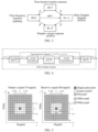
- FIG. 5 is a schematic diagram of pilot mapping of a delay-Doppler domain according to an embodiment of this application; FIG. 5 shows a manner that can be adopted for pilot mapping in the delay-Doppler domain.
- a sent signal includes a single-point pilot (a small square labeled 1) located at ( l p , k p ) , guard symbols (a shadeless part) having an area of (2 l ⁇ +1)(4 k v +1) -1 and surrounding the small square, and a data part (region other than the guard symbols) of MN- (2 l ⁇ +1)(4 k v +1).
- a delay-Doppler domain expression of the channel is obtained, that is, h ( v, ⁇ ) .
- the area of the guard symbols should satisfy the following condition: l ⁇ ⁇ ⁇ max M ⁇ ⁇ , k ⁇ ⁇ ⁇ max N ⁇ T
- ⁇ max and v max are the maximum time delay and the maximum Doppler frequency offset of all paths of the channel respectively.
- FIG. 5 corresponds to a single-port scenario, that is, only one set of reference signals needs to be sent.
- a plurality of antenna ports can be used to send multi-stream data simultaneously, to make full use of the degree of spatial freedom of the antennas and obtain the space diversity gain or improve the system throughput.
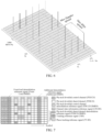
- FIG. 6 is a schematic diagram of mapping of a multi-port reference signal in a delay-Doppler domain according to an embodiment of this application.
- a pilot mapping manner shown in FIG. 6 is generated.
- 24 antenna ports correspond to 24 pilot signals.
- Each pilot signal adopts the form shown in FIG. 5 , that is, the pattern of a central point impulse signal plus guard symbols on both sides.
- FIG. 7 is a schematic diagram 1 of a reference signal and its mapping manner according to an embodiment of this application.
- PDCCH/PDSCH-DMRS are used to demodulate messages of control/data parts respectively.
- the receiving side first transforms a received sampling point into the TF domain, then performs channel estimation in the TF domain through the known DMRS, and uses a channel estimation result to perform equalization.
- overheads of the DMRS and available resources of data need to be traded off, it is necessary to use the limited DMRS to estimate the TF domain channel in the entire time slot, which inevitably leads to sparse mapping and interpolation operations.
- the DMRS in the radio frame is embodied as sparse mapping of the time domain and the frequency domain, and covers the entire bandwidth as much as possible to reduce the impact of frequency selective fading.
- a channel state information reference signal (Channel State Information Reference Signal, CSI-RS) is mainly used to measure CSI of a channel and perform beam management.
- the receiving side can obtain some key parameters of the physical layer such as delay, Doppler, and reference signal received power (Reference Signal Received Power, RSRP) through direct measurement, and then performs calculation according to an algorithm specified by a protocol to obtain and report measurement quantities defined by the protocol, such as a channel quality indicator (Channel quality indicator, CQI), a precoding matrix indicator (Precoding matrix indicator, PMI), a rank indicator (Rank indicator, RI), a CSI-RS resource indicator (CSI-RS Resource Indicator, CRI), and a layer indicator (Layer Indicator, LI).
- the CSI-RS is divided into NZP (non-zero-power)-CSI-RS and ZP (zero-power)-CSI-RP.
- the former is a CSI-RS signal generated based on a Gold sequence, and the latter can be considered as a zero-power CSI-RS "signal" sent on a CSI-RS port specified by the protocol.
- CSI-RS-based measurement can be divided into two types of measurement, where one is called channel measurement (channel measurement, CM), and the other is called IM (interference measurement), namely, interference measurement.
- the CM measurement mainly measures the above-mentioned various measurement quantities, and needs to use non-zero power (Non-Zero Power, NZP) CSI-RS/zero power (Zero Power, ZP) CSI-RS; and the interference measurement (Interference Measurement, IM) mainly measures inter-cell signal interference, and needs to use only a ZP-CSI-RS for measurement.
- NZP non-Zero Power
- ZP Zero Power
- IM Interference Measurement
- a phase tracking reference signal (Phase Tracking Reference Signal, PT-RS) is used to measure a phase noise superimposed by impact of non-ideality of hardware when a signal is sent and received, which is reflected as phase rotation of a received constellation diagram relative to a transmitted constellation diagram.
- PT-RS Phase Tracking Reference Signal
- the PT-RS defined by the communication system also correspondingly features sparse frequency domain mapping and dense time-domain mapping, as shown in FIG. 7 .
- FIG. 8 is a schematic diagram 2 of a reference signal and its mapping manner according to an embodiment of this application.
- a positioning reference signal that is, P (positioning)-RS, which exists as an optional feature of NR.
- the mapping of the P-RS is shown in FIG. 8 .
- Using the P-RS for performing positioning measurement depends on the following key measurement quantities: 1) RSRP, where using an attenuation degree of an electromagnetic wave reflected by the RSRP, and according to a mapping relationship of a channel model, a distance of the receiving side relative to the sending side; and 2) angle of departure (angle of departure, AoD) of a received signal, which is used to estimate an orientation of the receiving side relative to the sending side.
- the sending side needs to frequently adjust a sending beam to obtain fine angular resolution, so that the P-RS is mapped on each OFDM symbol.
- the measurement accuracy of the RSRP is related to the number of RS sample points, so that a comb-4/6 sparse mapping method is used in the frequency domain to balance overheads, a measurement effect, and multi-user resource multiplexing requirements.
- mapping rules and measurement methods of various pilots well meet needs of signal processing on the receiving side, but have disadvantages as follows: There are many types of reference signals, and it is necessary to design one set of individual configuration and indication procedures for each type of reference signal, making protocol design very complicated; and different mapping modes are defined for reference signals with different functions, which does not consider multiplexing of the reference signals, resulting in large resource overheads, where due to non-uniform reference signal design, a frame structure needs to be adjusted frequently as needed, and signaling indication overheads are also large.
- the embodiments of this application provide an interference measurement method and apparatus, and a device.
- the interference measurement method and apparatus, and the device provided in the embodiments of this application is described in detail below with reference to the accompanying drawings by using some embodiments and application scenarios thereof.
- FIG. 9 is a schematic flowchart 1 of an interference measurement method according to an embodiment of this application. As shown in FIG. 9 , the interference measurement method includes the following step 910 and step 920:
- this embodiment of this application can realize the transmission of the first pilot based on the OTFS system; and under the framework of the single-point pulse or sequence pilot in the delay-Doppler domain, the interference measurement and control method based on the OTFS system is realized. Therefore, excessive definition and cumbersome interpretation of the reference signal in the communication system can be avoided, and pilot overheads and signaling overheads can be saved.
- pilot mapping in a delay-Doppler (Delay-Doppler, DD) domain may be used for interference management.
- the received interference of the signal on the receiving side is regarded as a part of the equivalent channel, the estimation and elimination of the interference is essentially a part of the generalized channel estimation and equalization. Therefore, in the domain where the channel estimation and equalization is implemented, the interference management can also be implemented. Therefore, the interference measurement performed in the TF domain in the OFDM system can be migrated to the DD domain in the OTFS system.
- this embodiment of this application can use an IM-CSI-RS (a specially configured ZP-CSI-RS) for interference management. Since the modulation symbols of the OFDM system are multiplexed in the time-frequency domain, the interference power measurement (namely, interference measurement) can be performed through the blank resource in a specific position in the time slot (namely, reserved IM-CSI-RS position), and the magnitude of the interference on a specific time-frequency resource can be roughly measured, to complete the interference measurement.
- IM-CSI-RS a specially configured ZP-CSI-RS
- the sending side and the receiving side are a pair of communication nodes performing wireless communication.
- the interference sending side is an interference source when the receiving side performs measurement.
- the receiving side may be UE, and the sending side may be a base station of a current cell where the UE is located; and the interference sending side may be a base station of a neighboring cell.
- the sending side may first send an initial signal to the receiving side, but when the initial signal is received and measured on the receiving side, interference caused when the second pilot is sent by the interference sending side is further received and measured.
- the receiving side may receive a signal, and the received signal includes the second pilot sent by the interference sending side and the initial signal, so that the receiving side can measure the second pilot in the measurement position, that is, realize the interference measurement on the interference sending side.
- the statistical characteristics of the interference distribution in the resource occupied by the subframe can be obtained, and then used for the receiver algorithm to perform interference cancellation, or used for information reporting to perform interference control.
- performing interference measurement on the second pilot of the interference sending side based on signal transmission of the receiving side and the sending side using the orthogonal time frequency space OTFS system, and implementing interference measurement on the second pilot when the first pilot is transmitted in the OTFS system are applicable to interference measurement on various reference signals, to effectively save resources.
- the performing, by the receiving side, interference measurement on the interference sending side includes: performing, by the receiving side, interference measurement on the interference sending side in a delay-Doppler domain.
- the interference sending side uses the OTFS system
- the receiving side, the sending side, and the interference sending side all use the OTFS system.
- D-RE delay-Doppler domain Resource element
- the receiving side may perform interference measurement on the interference sending side in the delay-Doppler domain.
- the performing, by the receiving side, interference measurement on the interference sending side in a delay-Doppler domain includes:
- the interference management process may be triggered by the sending side.
- target configuration information required for the interference measurement may be determined first, for example, the target configuration information may be determined based on the first indication information of the sending side.
- the receiving side may further determine that the interference measurement is triggered. For example, it may be directly determined that the interference measurement is triggered because the target configuration information is received.
- the receiving side may perform the interference measurement on the interference sending side in the delay-Doppler domain based on the target configuration information.
- the determining, by the receiving side, target configuration information required for the interference measurement includes:
- the receiving side when determining target configuration information required for the interference measurement, may receive first indication information that is used for indicating the target configuration information and that is sent by the sending side, and then determine the target configuration information based on the first indication information.
- the determining, by the receiving side, that the interference measurement is triggered includes at least one of the following:
- the receiving side may receive first indication information used for indicating the target configuration information, and then determine that the interference measurement is triggered.
- the sending side may send part or all of the target configuration information to the receiving side through the first indication information, where the target configuration information may be information used for indicating an interference measurement position; and the sending side and the interference sending side can exchange pilot configuration information with each other through a specific communication protocol.
- the sending side and the interference sending side can exchange pilot configuration information through an X2 interface.
- the sending side may send the remaining target configuration information again to trigger interference measurement on the receiving side.
- the receiving side may directly determine that the interference measurement is triggered.
- the interference management process may be triggered by the receiving side itself.
- the receiving side determines, in a case of determining that a signal-to-interference-plus-noise ratio SINR is greater than a first threshold, that the interference measurement is triggered.
- the sending side may send part or all of the target configuration information to the receiving side through the first indication information, where the target configuration information may be information used for indicating an interference measurement position; and Subsequently, the receiving side may determine, in a case of determining that a signal-to-interference-plus-noise ratio SINR is greater than a first threshold, that the interference measurement is triggered; and then may perform the interference measurement on the interference sending side in the delay-Doppler domain based on the target configuration information.
- SINR signal-to-interference-plus-noise ratio
- the receiving side determines, in a case of determining that a bit error rate of a receiver is greater than a second threshold, that the interference measurement is triggered.
- the sending side may send part or all of the target configuration information to the receiving side through the first indication information, where the target configuration information may be information used for indicating an interference measurement position; and Subsequently, the receiving side may determine, in a case of determining that a bit error rate of a receiver is greater than a second threshold, that the interference measurement is triggered, and then may perform the interference measurement on the interference sending side in the delay-Doppler domain based on the target configuration information.
- the performing, by the receiving side, interference measurement on the interference sending side in a delay-Doppler domain includes:
- the receiving side may first trigger the interference management process and then obtain target configuration information.
- the receiving side performs interference measurement on the interference sending side, it may be first determined that the interference measurement is triggered. For example, it may be determined that the interference measurement is triggered based on information such as a signal-to-noise ratio.
- the receiving side may further determine target configuration information required for the interference measurement. For example, after requesting the target configuration information from the sending side, the receiving side may determine the target configuration information based on the first indication information returned by the sending side.
- the receiving side may perform the interference measurement on the interference sending side in the delay-Doppler domain based on the target configuration information.
- the determining, by the receiving side, that the interference measurement is triggered includes at least one of the following:
- the interference management process may be triggered by the receiving side itself.
- the receiving side may determine, in a case of determining that a signal-to-interference-plus-noise ratio SINR is greater than a first threshold, that the interference measurement is triggered.
- SINR signal-to-interference-plus-noise ratio
- the receiving side may determine, in a case of determining that a signal-to-interference-plus-noise ratio SINR is greater than a first threshold, that the interference measurement is triggered; then may request the target configuration information from the sending side, and obtain part or all of the target configuration information returned by the sending side through the first indication information, where the target configuration information may be information used for indicating an interference measurement position; and then may perform the interference measurement on the interference sending side in the delay-Doppler domain based on the target configuration information.
- SINR signal-to-interference-plus-noise ratio
- the receiving side determines, in a case of determining that a bit error rate of a receiver is greater than a second threshold, that the interference measurement is triggered.
- the receiving side may determine, in a case of determining that a bit error rate of a receiver is greater than a second threshold, that the interference measurement is triggered; then may request the target configuration information from the sending side, and obtain part or all of the target configuration information returned by the sending side through the first indication information, where the target configuration information may be information used for indicating an interference measurement position; and then may perform the interference measurement on the interference sending side in the delay-Doppler domain based on the target configuration information.
- the determining, by the receiving side, target configuration information required for the interference measurement includes:
- the receiving side may send interference measurement configuration request signaling to the sending side after determining that the interference measurement is triggered, to request the target configuration information.
- the sending side may send first indication information based on the interference measurement configuration request signaling, where the first indication information is used for indicating the target configuration information requested by the receiving side.
- the receiving side may determine the target configuration information based on the first indication information.
- the interference measurement configuration request signaling carries at least one of the following: uplink control information (Uplink Control Information, UCI), an uplink reference signal (e.g., Sounding Reference Signal, SRS), and an uplink medium access control control element (Medium Access Control Control Element, MAC CE).
- uplink control information Uplink Control Information, UCI
- an uplink reference signal e.g., Sounding Reference Signal, SRS
- an uplink medium access control control element Medium Access Control Control Element, MAC CE
- the interference measurement configuration request signaling carries one or more of the following: uplink control information UCI, an uplink reference signal such as SRS, or an uplink MAC CE.
- the target configuration information includes a resource position of the second pilot in a delay-Doppler domain resource grid, and a resource range of the interference measurement.
- the target configuration information may include a resource position of the second pilot in a delay-Doppler domain resource grid, and a resource range of the interference measurement.
- the resource position of the second pilot in the delay-Doppler domain resource grid and the resource range of the interference measurement can be determined after the sending side and the interference sending side exchange pilot configuration information (the resource position of the first pilot and/or the resource position of the second pilot) with each other through a specific communication protocol.
- the sending side and the interference sending side can exchange respective pilot configuration information through the X2 interface, which may include a resource position of the second pilot in a delay-Doppler domain resource grid, and may further include a resource range (interference measurement Gap) for the receiving side to perform interference measurement.
- the target configuration information includes a time length of the interference measurement, a frame structure of the interference sending side, and a resource position of the second pilot in a delay-Doppler domain resource grid; and transmission of a first signal is not performed in a measurement time, and the first signal is a signal sent by the sending side to the receiving side.
- the target configuration information may include a time length of the interference measurement, a frame structure of the interference sending side, and a resource position of the second pilot in a delay-Doppler domain resource grid.
- the time length of the interference measurement, the frame structure of the interference sending side, and the resource position of the second pilot in the delay-Doppler domain resource grid may be determined after the sending side and the interference sending side interact with each other through a specific communication protocol.
- the sending side and the interference sending side can exchange the above information through the X2 interface, which may include the time length of the interference measurement, the frame structure of the interference sending side, and the resource position of the second pilot in the delay-Doppler domain resource grid.
- the signaling sent by the sending side includes two parts:
- the signaling sent by the sending side may be a message for a specific user, such as downlink control information (Downlink Control Information, DCI) or a radio resource control (Radio Resource Control, RRC) message.
- DCI Downlink Control Information
- RRC Radio Resource Control
- the receiving side determines the interference measurement area according to the prior information in the signaling of the sending side. First, blind detection is performed on the area where the reference signal is sent by the interference sending side, and the receiving side performs interference channel measurement in the determined pilot area of the interference sending side.
- the sending side may not send the initial signal within this time length.
- transmission of a first signal is not performed in a measurement time, and the first signal is a signal sent by the sending side to the receiving side, to ensure that all the interference measured by the receiving side during the interference measurement is directed at the interference sending side.
- the target configuration information includes a time length of the interference measurement, a frame structure of the interference sending side, and a resource position of the second pilot in a delay-Doppler domain resource grid; and in the resource position of the second pilot in the delay-Doppler domain resource grid, transmission of a first signal is not performed in a resource grid corresponding to the delay-Doppler domain, and the first signal is a signal sent by the sending side to the receiving side.
- the target configuration information may include a time length of the interference measurement, a frame structure of the interference sending side, and a resource position of the second pilot in a delay-Doppler domain resource grid.
- the time length of the interference measurement, the frame structure of the interference sending side, and the resource position of the second pilot in the delay-Doppler domain resource grid may be determined after the sending side and the interference sending side interact with each other through a specific communication protocol.
- the sending side and the interference sending side can exchange the above information through the X2 interface, which may include the time length of the interference measurement, the frame structure of the interference sending side, and the resource position of the second pilot in the delay-Doppler domain resource grid.
- the sending side may not send the initial signal in the resource position of the second pilot in the delay-Doppler domain resource grid.
- transmission of a first signal is not performed, and the first signal is a signal sent by the sending side to the receiving side, to ensure that all the interference measured by the receiving side in the measurement range corresponding to the resource position of the second pilot in the delay-Doppler domain resource grid is directed at the interference sending side.
- the first indication information is carried in at least one of the following: a synchronization signal block (Synchronization Signal and PBCH block, SSB), a physical broadcast channel (Physical broadcast channel, PBCH), a system information block (System Information Block, SIB), DCI, RRC, and a MAC CE.
- a synchronization signal block Synchronization Signal and PBCH block, SSB
- PBCH Physical broadcast channel
- SIB System Information Block
- DCI RRC
- MAC CE MAC CE
- the first indication information may be carried in one or more of the following: an SSB, a PBCH, a SIB, DCI, RRC, or a MAC CE.
- the first indication information includes at least one of the following:
- the first indication information may directly include the target configuration information.
- the first indication information may include first direct indication information, used for directly indicating the target configuration information, for example, directly includes the target configuration information itself.
- the first indication information may include a first index, where the first index is used for indicating the target configuration information that corresponds to the first index and that is in a configuration information table, where the configuration information table includes at least one second index and at least one piece of configuration information, one second index corresponds to one piece of configuration information, and different second indexes correspond to different pieces of configuration information; and the first index is one of the at least one second index, and the target configuration information is one of the at least one piece of configuration information; and
- the indication configuration information table may include second indexes: an "index 1", an “index 2”, and an “index 3", where configuration information corresponding to the "index 1" is “configuration information A”, configuration information corresponding to the "index 2” is “configuration information B”, and configuration information corresponding to the "index 3" is “configuration information C”. If the first index indicates the "index 2”, it may be determined that the target configuration information includes the "configuration information B" corresponding to the "index 2".
- N types of interference power measurement GAP patterns may be indicated through the above table lookup, and ⁇ log 2 N ⁇ bits may be used to indicate the first index.
- the determining, by the receiving side, target configuration information required for the interference measurement includes: directly determining, by the receiving side, the target configuration information.
- the receiving side can directly determine the target configuration information by itself, for example, can directly determine an IM detection area (including the position of the second pilot in the delay-Doppler domain resource grid) by itself, which can be used as a measurement area for interference measurement in the delay-Doppler domain resource grid.
- the target configuration information for example, can directly determine an IM detection area (including the position of the second pilot in the delay-Doppler domain resource grid) by itself, which can be used as a measurement area for interference measurement in the delay-Doppler domain resource grid.
- the method further includes: sending, by the receiving side, the target configuration information to the sending side, where the target configuration information is used for instructing the interference sending side through the sending side to configure the second pilot based on the target configuration information.
- the receiving side can directly determine the target configuration information by itself, and on this basis, the receiving side needs to send the target configuration information determined by the receiving side itself to the sending side, and the sending side learns the target configuration information determined by the receiving side itself and then needs to further indicate the target configuration information to the interference sending side, so that the interference sending side determines the configuration of the second pilot, that is, configures the second pilot in the IM detection area for interference measurement, to ensure that the receiving side can accurately measure the second pilot within the resource range of the interference measurement.
- the performing, by the receiving side, interference measurement on the interference sending side in a delay-Doppler domain includes:
- the receiving side can determine a measurement area of the interference measurement in the delay-Doppler domain resource grid based on the target configuration information; and then can perform the interference measurement on the interference sending side in the measurement area.
- the determining, by the receiving side, a measurement area of the interference measurement in the delay-Doppler domain resource grid based on the target configuration information includes:
- the receiving side when the receiving side determines a measurement area of the interference measurement in the delay-Doppler domain resource grid based on the target configuration information, the receiving side can first determine a resource position of the second pilot in the delay-Doppler domain resource grid based on the target configuration information; and can determine that the measurement area is the resource position of the second pilot in the delay-Doppler domain resource grid, where the resource position of the second pilot of the interference sending side in the delay-Doppler domain resource grid does not coincide with a resource grid range corresponding to the first pilot.
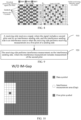
- FIG. 10 is a schematic diagram 1 of pilot mapping of a delay-Doppler domain resource grid according to an embodiment of this application.
- FIG. 11 is a schematic diagram 2 of pilot mapping of a delay-Doppler domain resource grid according to an embodiment of this application.
- FIG. 12 is a schematic diagram 1 of a measurement area of a delay-Doppler domain resource grid according to an embodiment of this application.
- FIG. 13 is a schematic diagram 2 of a measurement area of a delay-Doppler domain resource grid according to an embodiment of this application.
- FIG. 10 shows a single-point pulse pilot in the DD domain. It can be seen that after channel coupling, the distribution of sample points in the DD domain on the receiving side becomes the form in FIG. 12 .
- the part filled with oblique grids in the bold box is not interfered by the offset of the data symbols, and therefore can be used for pilot detection to perform channel measurement. If the system requires interference measurement, it is necessary to introduce a new blank D-RE (the part in the bold box in FIG. 11 can be called interference measurement Gap, interference measurement required Gap, interference measurement range, or interference measurement area) in addition to the original GAP in FIG. 10 to perform interference measurement. As shown in FIG. 11 , the additional D-RE part introduced in the box is used for interference measurement. It can be seen that according to the pilot and data symbol mapping presented in FIG. 11 , it becomes the form of FIG.
- sending of the second pilot of the interference sending side can be configured in the position of the IM detection surrounded by the box in FIG 13 .
- the known second pilot signal of the interference sending side exists in the position of the IM detection, and then the pilot power component detection on the DD domain grid points can be performed in the IM detection area to estimate the interference channel between the interference sending side and the receiving side.
- the IM detection area (the resource position of the second pilot in the delay-Doppler domain resource grid) may satisfy the following conditions:
- the second pilot of the interference sending side is in the IM detection area, and the maximum delay and Doppler offsets caused by interference channel coupling are still in the IM detection area. Therefore, the receiving side needs to know the position of the second pilot of the interference sending side; and the sending side can adjust the sending position of its own first pilot, so that the first pilot is connected to the second pilot of the interference sending side to save part of the Gap overheads.
- the resource position of the second pilot of the interference sending side in the delay-Doppler domain resource grid does not coincide with a resource grid range corresponding to the first pilot, and the resource position of the second pilot of the interference sending side in the delay-Doppler domain resource grid may be adjacent to or connected to the resource grid range corresponding to the first pilot.
- the performing, by the receiving side, interference measurement on the interference sending side in a delay-Doppler domain includes:
- FIG. 14 is a schematic diagram 3 of pilot mapping of a delay-Doppler domain resource grid according to an embodiment of this application.
- FIG. 15 is a schematic diagram 3 of a measurement area of a delay-Doppler domain resource grid according to an embodiment of this application. As shown in FIG. 14 and FIG.
- the original pilot area (the resource grid range of the delay-Doppler domain corresponding to the first pilot) (pilot pulse + gap) can be reused as an IM detection area, and the interference sending side sends a pilot in this reused area.
- the channel estimation of the current frame of the cell of the receiving side can be resolved in another manner: For example, the channel estimation of the previous frame is directly used if the channel of a plurality of consecutive frames remains unchanged, or channel prediction is performed if the channel of a plurality of consecutive frames changes regularly.
- the receiving side when the receiving side determines a measurement area of the interference measurement in the delay-Doppler domain resource grid based on the target configuration information, the receiving side can determine a measurement area in a resource grid range of the delay-Doppler domain corresponding to the first pilot.
- the determining, by the receiving side, a measurement area in a resource grid range of the delay-Doppler domain corresponding to the first pilot includes:
- the measurement area of the interference pilot may be consistent with that of the original pilot.
- the interference channel and the communication channel may be different in delay and Doppler, which also needs to be considered during Gap configuration.
- the interference measurement may be triggered by the receiving side itself or by the sending side.
- the prior information about the pilot position of the interference sending side may be configured by the sending side to the receiving side.
- the maximum delay and Doppler of the communication channel of the sending side can be ⁇ max 0 and ⁇ max 0 and the maximum delay and Doppler of the interference channel of the interference sending side can be ⁇ max 1 and ⁇ max 1 , and when ⁇ max 0 > ⁇ max 1 and ⁇ max 0 > ⁇ max 1 , the Gap required for interference channel measurement needs to be reconfigured.
- ⁇ max 0 and ⁇ max 0 can be fed back by the receiving side or obtained through uplink measurement using channel reciprocity; but the sending side has no way of knowing the prior information ⁇ max 1 and ⁇ max 1 of the channel between the interference sending side and the receiving side. Therefore, when determining the actually required Gap, the receiving side can determine the measurement area based on presetting, or determine the measurement area based on protocol pre-configuration, or determine the measurement area based on the second indication information of the sending side.
- the receiving side can determine, based on presetting, that the measurement area is the resource grid range corresponding to the first pilot.
- the receiving side can determine, based on protocol pre-configuration, that the measurement area is the resource grid range corresponding to the first pilot.
- the receiving side can determine, based on second indication information of the sending side, that the measurement area is the resource grid range corresponding to the first pilot.
- the Gap area (measurement area) required for interference measurement may not need to be indicated, and the resource grid area of the first pilot directly continues to be used.
- the sending side may directly send a 1-bit user-specific message to trigger interference management, instructing the receiving side to measure interference in the resource grid region of the first pilot.
- the determining, by the receiving side, a measurement area in a resource grid range of the delay-Doppler domain corresponding to the first pilot includes: determining, by the receiving side, a target position coordinate of the measurement area based on third indication information of the sending side.
- the receiving side when the receiving side determines a measurement area in a resource grid range of the delay-Doppler domain corresponding to the first pilot, where the measurement area may be part of the resource grid range corresponding to the first pilot, the receiving side can determine a target position coordinate of the measurement area based on third indication information of the sending side.
- the third indication information includes:
- the third indication information sent by the sending side may be a broadcast message such as PBCH in SSB or SIB message, or may be a user-specific message such as DCI or RRC message.
- PBCH PBCH in SSB or SIB message
- DCI DCI or RRC message
- the sending side may directly send the target position coordinate of the measurement area to the receiving side through the third indication information.
- the third indication information may include second direct indication information, which is used to directly indicate the target position coordinate of the measurement area.
- the third indication information may include a third index, where the third index is used for indicating the target position coordinate that corresponds to the second index and that is in at least one position coordinate set, where the at least one position coordinate set includes at least one fourth index and at least one position coordinate, one fourth index corresponds to one position coordinate, and different fourth indexes correspond to different position coordinates; and the third index is one of the at least one fourth index, and the target position coordinate is one of the at least one position coordinate; and
- the indication configuration information table may include fourth indexes: an "index 4", an "index 5", and an "index 6", where the position coordinate corresponding to "index 4" is “position coordinate D", the position coordinate corresponding to "index 5" is “position coordinate E”, and the position coordinate corresponding to "index 6" is “position coordinate F”. If the third index indicates "index 4", it can be determined that the target position coordinate of the measurement area includes the "position coordinate D" corresponding to the "index 4".
- the method further includes: sending, by the receiving side, fourth indication information to the sending side, where the fourth indication information is used for indicating whether the target position coordinate is available.
- the receiving side can send fourth indication information to the sending side, to indicate whether the target position coordinate is available.
- the receiving side may send 1-bit feedback information (fourth indication information), indicating whether the currently selected interference measurement area is appropriate (whether the target position coordinate is available).
- the sending side may reconfigure the interference measurement area according to the feedback message, which may also be referred to as an interference measurement Gap area or an interference measurement range.
- the current configuration is ⁇ [ k p - 2 k v - k j , k p + 2 k v + k j ], [ l p - l v - l j , l p + l v + l j ] ⁇
- the configuration becomes ⁇ [ k p - 2k v - k j +1 , k p + 2 k v + k j +1 ], [ l p - l v - l j +1 , l p + l v + l j +1 ] ⁇ and is indicated to the receiving side.
- the received fourth indication information is 1, the configuration remains unchanged, and 1 bit may be used to indicate to the receiving side or not.
- the signal includes a first time unit used for indicating the interference measurement; and the performing, by the receiving side, interference measurement on the interference sending side includes:
- both the receiving side and the sending side adopt the OTFS system
- the interference sending side adopts the OFDM system
- the problems to be faced in the interference control are more complicated.
- the modulation symbols are mapped in the TF domain
- the interference on some subcarriers in the TF domain undergoes SFFT and then is reflected as the interference of the entire area in the DD domain. Therefore, for the OTFS system, if the interference brought by the OFDM system is to be measured, it is necessary to measure the D-RE resources in the entire time slot.
- the pilot mapping mode of the OFDM system is to hash and place a reference signal sequence on the TF domain resource grid according to a certain pattern
- the transformed reference signal sequence is distributed throughout the entire DD domain resource grid. If the reference signal and data in the TF domain are orthogonally multiplexed in the same subframe in this case, the reference signal and data transformed to the DD domain are non-orthogonally superimposed on a D-RE, which is not conducive to detection. Therefore, for the coexistence system of OTFS and OFDM, the interference measurement can be carried out in the TF domain.
- the receiving side when performing interference measurement in the TF domain, can first determine a time frequency domain resource position corresponding to the second pilot; and then perform the interference measurement on the interference sending side based on the first time unit and the time frequency domain resource position corresponding to the second pilot.
- the first time unit is blank, or the first time unit includes the first pilot, or the first time unit includes the first pilot and transmission data; and the determining, by the receiving side, a time frequency domain resource position corresponding to the second pilot includes:
- the receiving side can receive sixth indication information sent by the sending side, where the sixth indication information is used for indicating the time frequency domain resource position corresponding to the second pilot; and then the receiving side can determine the time frequency domain resource position corresponding to the second pilot based on the sixth indication information.
- the first time unit may be an interference measurement subframe or another communication time unit, which is not limited in this embodiment of this application.
- the sending side can configure an interference measurement subframe, which is a blank subframe, and no signal or data is sent on its resources, and the sending side can indicate the position of the interference measurement subframe in the radio frame by broadcasting or receiving-side dedicated signaling, to trigger the receiving-side measurement behavior. Then, the receiving side can obtain the position of the second pilot in the TF domain based on the sixth indication information. Then, the receiving side can perform neighboring cell interference channel measurement (measurement for the second pilot of the interference sending side) in the known pilot position in the TF domain, and can achieve accurate measurement.
- the sending side can configure an interference measurement subframe, which is a subframe containing only the first pilot, and only the first pilot in the DD domain is sent on its resources; and the sending side can indicate the position of the interference measurement subframe in the radio frame by broadcasting or receiving-side dedicated signaling, to trigger the receiving-side measurement behavior. Then, the receiving side can obtain the position of the second pilot in the TF domain based on the sixth indication information. Then, the receiving side can perform neighboring cell interference channel measurement (measurement for the second pilot of the interference sending side) in the known pilot position in the TF domain, and can achieve accurate measurement.
- an interference measurement subframe which is a subframe containing only the first pilot, and only the first pilot in the DD domain is sent on its resources
- the sending side can indicate the position of the interference measurement subframe in the radio frame by broadcasting or receiving-side dedicated signaling, to trigger the receiving-side measurement behavior.
- the receiving side can obtain the position of the second pilot in the TF domain based on the sixth indication information. Then, the receiving
- the sending side can configure an interference measurement subframe, which is a subframe containing only the first pilot, and only the first pilot in the DD domain is sent on its resources; and the sending side can indicate the position of the interference measurement subframe in the radio frame by broadcasting or receiving-side dedicated signaling, to trigger the receiving-side measurement behavior.
- the receiving side can convert the received signal sample points to the DD domain, and use the DD domain pilot detection method to obtain the DD domain channel, and then the component value of the received pilot on each RE in the TF domain is calculated, where the pilot components are subtracted from the received signal to obtain the neighboring cell interference signal and the noise part.
- the receiving side can obtain the position of the second pilot in the TF domain based on the sixth indication information.
- the receiving side can perform neighboring cell interference channel measurement (measurement for the second pilot of the interference sending side) in the known pilot position in the TF domain.
- the sending side can configure an interference measurement subframe, which is a subframe containing the first pilot and data that are orthogonal on the DD domain resource; the sending side can indicate the position of the interference measurement subframe in the radio frame by broadcasting or receiving-side dedicated signaling, to trigger the receiving-side measurement behavior. Then, the receiving side can convert the received signal sample points to the DD domain, use the DD domain pilot detection method to obtain the DD domain channel, and use the estimated channel to demodulate the DD domain data symbols. Then, the component value of the received DD domain pilot data transformed into the TF domain on each RE can be calculated. The components are subtracted from the received signal to obtain the neighboring cell interference signal and the noise part.
- the receiving side can obtain the position of the second pilot in the TF domain based on the sixth indication information. Then, the receiving side can perform neighboring cell interference channel measurement (measurement for the second pilot of the interference sending side) in the known pilot position in the TF domain.
- the introduction of additional overheads can be avoided by configuring the interference measurement subframe.
- the first time unit is blank, or the first time unit includes the first pilot, or the first time unit includes the first pilot and transmission data; and the determining, by the receiving side, a time frequency domain resource position corresponding to the second pilot of the interference sending side includes: performing, by the receiving side, blind detection, to determine the time frequency domain resource position corresponding to the second pilot.
- the receiving side can perform blind detection, to determine the time frequency domain resource position corresponding to the second pilot.
- the first time unit may be an interference measurement subframe or another communication time unit, which is not limited in this embodiment of this application.
- the sending side can configure an interference measurement subframe, which is a blank subframe, and no signal or data is sent on its resources, and the sending side can indicate the position of the interference measurement subframe in the radio frame by broadcasting or receiving-side dedicated signaling, to trigger the receiving-side measurement behavior. Then, the receiving side can perform blind detection to determine the time-frequency domain resource position corresponding to the second pilot. Then, the receiving side can perform neighboring cell interference channel measurement (measurement for the second pilot of the interference sending side) in the known pilot position in the TF domain, and can achieve accurate measurement.
- the sending side can configure an interference measurement subframe, which is a subframe containing only the first pilot, and only the first pilot in the DD domain is sent on its resources; and the sending side can indicate the position of the interference measurement subframe in the radio frame by broadcasting or receiving-side dedicated signaling, to trigger the receiving-side measurement behavior. Then, the receiving side can perform blind detection to determine the time-frequency domain resource position corresponding to the second pilot. Then, the receiving side can perform neighboring cell interference channel measurement (measurement for the second pilot of the interference sending side) in the known pilot position in the TF domain, and can achieve accurate measurement.
- an interference measurement subframe which is a subframe containing only the first pilot, and only the first pilot in the DD domain is sent on its resources
- the sending side can indicate the position of the interference measurement subframe in the radio frame by broadcasting or receiving-side dedicated signaling, to trigger the receiving-side measurement behavior.
- the receiving side can perform blind detection to determine the time-frequency domain resource position corresponding to the second pilot.
- the receiving side can perform
- the sending side can configure an interference measurement subframe, which is a subframe containing only the first pilot, and only the first pilot in the DD domain is sent on its resources; and the sending side can indicate the position of the interference measurement subframe in the radio frame by broadcasting or receiving-side dedicated signaling, to trigger the receiving-side measurement behavior.
- the receiving side can convert the received signal sample points to the DD domain, and use the DD domain pilot detection method to obtain the DD domain channel, and then the component value of the received pilot on each RE in the TF domain is calculated, where the pilot components are subtracted from the received signal to obtain the neighboring cell interference signal and the noise part.
- the receiving side can perform blind detection to determine the time-frequency domain resource position corresponding to the second pilot.
- the receiving side can perform neighboring cell interference channel measurement (measurement for the second pilot of the interference sending side) in the known pilot position in the TF domain.
- the sending side can configure an interference measurement subframe, which is a subframe containing the first pilot and data that are orthogonal on the DD domain resource; the sending side can indicate the position of the interference measurement subframe in the radio frame by broadcasting or receiving-side dedicated signaling, to trigger the receiving-side measurement behavior. Then, the receiving side can convert the received signal sample points to the DD domain, use the DD domain pilot detection method to obtain the DD domain channel, and use the estimated channel to demodulate the DD domain data symbols. Then, the component value of the received DD domain pilot data transformed into the TF domain on each RE can be calculated. The components are subtracted from the received signal to obtain the neighboring cell interference signal and the noise part.
- the receiving side can perform blind detection to determine the time-frequency domain resource position corresponding to the second pilot. Then, the receiving side can perform neighboring cell interference channel measurement (measurement for the second pilot of the interference sending side) in the known pilot position in the TF domain.
- the performing interference measurement on the interference sending side includes: performing, by the receiving side, measurement on an interference channel based on the time frequency domain resource position corresponding to the second pilot.
- the receiving side can perform measurement on an interference channel based on the time frequency domain resource position corresponding to the second pilot.
- the performing interference measurement on the interference sending side further includes:
- the sending side can configure an interference measurement subframe, which is a subframe containing the first pilot and data that are orthogonal on the DD domain resource; the sending side can indicate the position of the interference measurement subframe in the radio frame by broadcasting or receiving-side dedicated signaling, to trigger the receiving-side measurement behavior. Then, the receiving side can convert the received signal sample points to the DD domain, use the DD domain pilot detection method to obtain the DD domain channel, and use the estimated channel to demodulate the DD domain data symbols. Then, the component value of the received DD domain pilot data transformed into the TF domain on each RE can be calculated. The components are subtracted from the received signal to obtain the neighboring cell interference signal and the noise part.
- an interference measurement subframe which is a subframe containing the first pilot and data that are orthogonal on the DD domain resource
- the sending side can indicate the position of the interference measurement subframe in the radio frame by broadcasting or receiving-side dedicated signaling, to trigger the receiving-side measurement behavior.
- the receiving side can convert the received signal sample
- the receiving side can perform blind detection to determine the time-frequency domain resource position corresponding to the second pilot. Then, the receiving side can perform neighboring cell interference channel measurement (measurement for the second pilot of the interference sending side) in the known pilot position in the TF domain.
- the sending side can configure an interference measurement subframe, which is a subframe containing only the first pilot, and only the first pilot in the DD domain is sent on its resources; and the sending side can indicate the position of the interference measurement subframe in the radio frame by broadcasting or receiving-side dedicated signaling, to trigger the receiving-side measurement behavior.
- the receiving side can convert the received signal sample points to the DD domain, and use the DD domain pilot detection method to obtain the DD domain channel, and then the component value of the received pilot on each RE in the TF domain is calculated, where the pilot components are subtracted from the received signal to obtain the neighboring cell interference signal and the noise part.
- the receiving side can perform blind detection to determine the time-frequency domain resource position corresponding to the second pilot.
- the receiving side can perform neighboring cell interference channel measurement (measurement for the second pilot of the interference sending side) in the known pilot position in the TF domain.
- the performing, by the receiving side, interference measurement on the interference sending side includes:
- the interference measurement may not be pilot-based interference channel estimation, and may only be used to estimate the neighboring cell interference power level.
- the DD domain Gap resource used for the interference measurement on the receiving side does not need to overlap with the pilot on the interference sending side and its Gap resource.
- a blank IM Gap can be added to the right of the Gap resource of the pilot required for communication.
- the IM Gap can be configured by the sending side, and the pilot position of the interference sending side does not need to be considered.
- the DD domain sample point set received by the receiving side is shown in FIG. 12 , and the receiving side counts the average interference power at the sample points within the range of the bold box.
- a more overhead-saving sending manner may be further used.
- the sending side sends no pilot in the IM stage, but still sends data.
- the original pilot area (pilot pulse + gap) can be reused as an IM detection area, and the interference sending side sends a pilot in this reused area, as shown in FIG. 11 and FIG. 12 .
- the channel estimation of the current frame of the cell of the receiving side can be resolved in another manner: For example, the channel estimation of the previous frame is directly used if the channel of a plurality of consecutive frames remains unchanged, or channel prediction is performed if the channel of a plurality of consecutive frames changes regularly.
- rate matching in the DD domain can be further performed for the IM Gap.
- the channel coding LDPC, Polar, or the like
- the channel coding can be controlled to achieve the required code rate by adjusting the size of the IM Gap resource and changing the number of D-REs that actually carry data.
- performing interference measurement on the second pilot of the interference sending side based on signal transmission of the receiving side and the sending side using the orthogonal time frequency space OTFS system, and implementing interference measurement on the second pilot when the first pilot is transmitted in the OTFS system are applicable to interference measurement on various reference signals, to effectively save resources.
- FIG. 16 is a schematic flowchart 2 of an interference measurement method according to an embodiment of this application. As shown in FIG. 16 , the method includes the following step 1600:
- Step 1600 A sending side sends an initial signal, where the initial signal is used by the receiving side to perform receiving measurement on a first pilot of the sending side;
- this embodiment of this application can realize the transmission of the first pilot based on the OTFS system; and under the framework of the single-point pulse or sequence pilot in the delay-Doppler domain, the interference measurement and control method based on the OTFS system is realized. Therefore, excessive definition and cumbersome interpretation of the reference signal in the communication system can be avoided, and pilot overheads and signaling overheads can be saved.
- pilot mapping in a DD domain may be used for interference management. If the received interference of the signal on the receiving side is regarded as a part of the equivalent channel, the estimation and elimination of the interference is essentially a part of the generalized channel estimation and equalization. Therefore, in the domain where the channel estimation and equalization is implemented, the interference management can also be implemented. Therefore, the interference measurement performed in the TF domain in the OFDM system can be migrated to the DD domain in the OTFS system.
- this embodiment of this application can use an IM-CSI-RS (a specially configured ZP-CSI-RS) for interference management. Since the modulation symbols of the OFDM system are multiplexed in the time-frequency domain, the interference power measurement (namely, interference measurement) can be performed through the blank resource in a specific position in the time slot (namely, reserved IM-CSI-RS position), and the magnitude of the interference on a specific time-frequency resource can be roughly measured, to complete the interference measurement.
- IM-CSI-RS a specially configured ZP-CSI-RS
- the sending side and the receiving side are a pair of communication nodes performing wireless communication.
- the interference sending side is an interference source when the receiving side performs measurement.
- the sending side and the receiving side are a base station and a UE of a current cell
- the interference sending side is a base station of a neighboring cell.
- the sending side may first send an initial signal to the receiving side, but when the initial signal is received and measured on the receiving side, interference caused when the second pilot is sent by the interference sending side is further received and measured.
- the receiving side may receive a signal, and the received signal includes the second pilot sent by the interference sending side and the initial signal, so that the receiving side can measure the second pilot in the measurement position, that is, realize the interference measurement on the interference sending side.
- the statistical characteristics of the interference distribution in the resource occupied by the subframe can be obtained, and then used for the receiver algorithm to perform interference cancellation, or used for information reporting to perform interference control.
- performing interference measurement on the second pilot of the interference sending side based on signal transmission of the receiving side and the sending side using the orthogonal time frequency space OTFS system, and implementing interference measurement on the second pilot when the first pilot is transmitted in the OTFS system are applicable to interference measurement on various reference signals, to effectively save resources.
- performing interference measurement on the second pilot of the interference sending side based on signal transmission of the receiving side and the sending side using the orthogonal time frequency space OTFS system, and implementing interference measurement on the second pilot when the first pilot is transmitted in the OTFS system are applicable to interference measurement on various reference signals, to effectively save resources.
- the method further includes: sending, by the sending side, first indication information to the receiving side, where the first indication information is used for indicating target configuration information required for the interference measurement.
- the interference management process may be triggered by the sending side.
- the sending side can send first indication information to the receiving side, to indicate target configuration information required for the interference measurement to the receiving side; and when determining target configuration information required for the interference measurement, the receiving side may receive first indication information that is used for indicating the target configuration information and that is sent by the sending side, and then determine the target configuration information based on the first indication information.
- target configuration information required for the interference measurement may be determined first, for example, the target configuration information may be determined based on the first indication information of the sending side.
- the method further includes:
- the receiving side may send interference measurement configuration request signaling to the sending side after determining that the interference measurement is triggered, to request the target configuration information.
- the sending side may send first indication information based on the interference measurement configuration request signaling, where the first indication information is used for indicating the target configuration information requested by the receiving side.
- the receiving side may determine the target configuration information based on the first indication information.
- the receiving side may determine, in a case of determining that a signal-to-interference-plus-noise ratio SINR is greater than a first threshold, that the interference measurement is triggered.
- the receiving side may determine, in a case of determining that a signal-to-interference-plus-noise ratio SINR is greater than a first threshold, that the interference measurement is triggered; then may request the target configuration information from the sending side, and obtain part or all of the target configuration information returned by the sending side through the first indication information, where the target configuration information may be information used for indicating an interference measurement position; and then may perform the interference measurement on the interference sending side in the delay-Doppler domain based on the target configuration information.
- SINR signal-to-interference-plus-noise ratio
- the receiving side determines, in a case of determining that a bit error rate of a receiver is greater than a second threshold, that the interference measurement is triggered.
- the receiving side may determine, in a case of determining that a bit error rate of a receiver is greater than a second threshold, that the interference measurement is triggered; then may request the target configuration information from the sending side, and obtain part or all of the target configuration information returned by the sending side through the first indication information, where the target configuration information may be information used for indicating an interference measurement position; and then may perform the interference measurement on the interference sending side in the delay-Doppler domain based on the target configuration information.
- the interference measurement configuration request signaling carries at least one of the following: uplink control information UCI, an uplink reference signal such as SRS, and an uplink MAC CE.
- the interference measurement configuration request signaling carries one or more of the following: uplink control information UCI, an uplink reference signal such as SRS, or an uplink MAC CE.
- the first indication information is carried in at least one of the following: an SSB, a PBCH, a SIB, DCI, RRC, and a MAC CE.
- the first indication information may be carried in one or more of the following: SSB, PBCH, SIB, DCI, Radio Resource Control RRC, or Medium Access Control Control Element MAC CE.
- the first indication information includes at least one of the following:
- the first indication information may directly include the target configuration information.
- the first indication information may include first direct indication information, used for directly indicating the target configuration information, for example, directly includes the target configuration information itself.
- the first indication information may include a first index, where the first index is used for indicating the target configuration information that corresponds to the first index and that is in a configuration information table, where the configuration information table includes at least one second index and at least one piece of configuration information, one second index corresponds to one piece of configuration information, and different second indexes correspond to different pieces of configuration information; and the first index is one of the at least one second index, and the target configuration information is one of the at least one piece of configuration information; and
- the indication configuration information table may include second indexes: an "index 1", an “index 2”, and an “index 3", where configuration information corresponding to the "index 1" is “configuration information A”, configuration information corresponding to the "index 2” is “configuration information B”, and configuration information corresponding to the "index 3" is “configuration information C”. If the first index indicates the " index 2", it may be determined that the target configuration information includes the "configuration information B" corresponding to the "index 2".
- K types of interference power measurement GAP patterns may be indicated through the above table lookup, and ⁇ log 2 N ⁇ bits may be used to indicate the first index.
- the target configuration information includes a resource position of the second pilot in a delay-Doppler domain resource grid, and a resource range of the interference measurement.
- the target configuration information may include a resource position of the second pilot in a delay-Doppler domain resource grid, and a resource range of the interference measurement.
- the resource position of the second pilot in the delay-Doppler domain resource grid and the resource range of the interference measurement can be determined after the sending side and the interference sending side exchange pilot configuration information (the resource position of the first pilot and/or the resource position of the second pilot) with each other through a specific communication protocol.
- the sending side and the interference sending side can exchange respective pilot configuration information through the X2 interface, which may include a resource position of the second pilot in a delay-Doppler domain resource grid, and may further include a resource range for the receiving side to perform interference measurement.
- the target configuration information includes a time length of the interference measurement, a frame structure of the interference sending side, and a resource position of the second pilot in a delay-Doppler domain resource grid; and transmission of a first signal is not performed in a measurement time, and the first signal is a signal sent by the sending side to the receiving side.
- the target configuration information may include a time length of the interference measurement, a frame structure of the interference sending side, and a resource position of the second pilot in a delay-Doppler domain resource grid.
- the time length of the interference measurement, the frame structure of the interference sending side, and the resource position of the second pilot in the delay-Doppler domain resource grid may be determined after the sending side and the interference sending side interact with each other through a specific communication protocol.
- the sending side and the interference sending side can exchange the above information through the X2 interface, which may include the time length of the interference measurement, the frame structure of the interference sending side, and the resource position of the second pilot in the delay-Doppler domain resource grid.
- the signaling sent by the sending side includes two parts:
- the signaling sent by the sending side may be a message for a specific user, such as DCI or RRC message.
- the receiving side determines the interference measurement area according to the prior information in the signaling of the sending side. First, blind detection is performed on the area where the reference signal is sent by the interference sending side, and the receiving side performs interference channel measurement in the determined pilot area of the interference sending side.
- the sending side may not send the initial signal within this time length.
- transmission of a first signal is not performed in a measurement time, and the first signal is a signal sent by the sending side to the receiving side, to ensure that all the interference measured by the receiving side during the interference measurement is directed at the interference sending side.
- the target configuration information includes a time length of the interference measurement, a frame structure of the interference sending side, and a resource position of the second pilot in a delay-Doppler domain resource grid; and in the resource position of the second pilot in the delay-Doppler domain resource grid, transmission of a first signal is not performed in a resource grid corresponding to the delay-Doppler domain, and the first signal is a signal sent by the sending side to the receiving side.
- the target configuration information may include a time length of the interference measurement, a frame structure of the interference sending side, and a resource position of the second pilot in a delay-Doppler domain resource grid.
- the time length of the interference measurement, the frame structure of the interference sending side, and the resource position of the second pilot in the delay-Doppler domain resource grid may be determined after the sending side and the interference sending side interact with each other through a specific communication protocol.
- the sending side and the interference sending side can exchange the above information through the X2 interface, which may include the time length of the interference measurement, the frame structure of the interference sending side, and the resource position of the second pilot in the delay-Doppler domain resource grid.
- the sending side may not send the initial signal in the resource position of the second pilot in the delay-Doppler domain resource grid.
- transmission of a first signal is not performed, and the first signal is a signal sent by the sending side to the receiving side, to ensure that all the interference measured by the receiving side in the measurement range corresponding to the resource position of the second pilot in the delay-Doppler domain resource grid is directed at the interference sending side.
- the method further includes:
- the receiving side can directly determine the target configuration information by itself, for example, can directly determine the interference measurement area (IM detection area) by itself, that is, the position of the second pilot in the delay-Doppler domain resource grid can be used as a measurement area for interference measurement in the delay-Doppler domain resource grid.
- IM detection area the interference measurement area
- the receiving side can directly determine the target configuration information by itself, and on this basis, the receiving side needs to send the target configuration information determined by the receiving side itself to the sending side, and the sending side learns the target configuration information determined by the receiving side itself and then needs to further indicate the target configuration information to the interference sending side, so that the interference sending side determines the configuration of the second pilot, that is, configures the second pilot in the IM detection area for interference measurement, to ensure that the receiving side can accurately measure the second pilot within the resource range of the interference measurement.
- the method further includes: sending, by the sending side, second indication information to the receiving side, where the second indication information is used for indicating that a measurement area is a resource grid range corresponding to the first pilot.
- the measurement area of the interference pilot may be consistent with that of the original pilot.
- the interference channel and the communication channel may be different in delay and Doppler, which also needs to be considered during Gap configuration.
- the interference measurement may be triggered by the receiving side itself or by the sending side.
- the prior information about the pilot position of the interference sending side may be configured by the sending side to the receiving side.
- the maximum delay and Doppler of the communication channel of the sending side can be ⁇ max 0 and ⁇ max 0 and the maximum delay and Doppler of the interference channel of the interference sending side can be ⁇ max 1 and ⁇ max 1 , and when ⁇ max 0 > ⁇ max 1 and ⁇ max 0 > ⁇ max 1 , the Gap required for interference channel measurement needs to be reconfigured.
- ⁇ max 0 and ⁇ max 0 can be fed back by the receiving side or obtained through uplink measurement using channel reciprocity; but the sending side has no way of knowing the prior information ⁇ max 1 and ⁇ max 1 of the channel between the sending side and the receiving side. Therefore, when determining the actually required Gap, the receiving side can determine the measurement area based on presetting, or determine the measurement area based on protocol pre-configuration, or determine the measurement area based on the second indication information of the sending side.
- the sending side can send second indication information to the receiving side, to indicating that the measurement area is a resource grid range corresponding to the first pilot to the receiving side; and the receiving side can determine, based on second indication information of the sending side, that the measurement area is the resource grid range corresponding to the first pilot.
- the sending side may directly send a 1-bit user-specific message to trigger interference management, instructing the receiving side to measure interference in the resource grid region of the first pilot.
- the receiving side when the receiving side determines a measurement area in a resource grid range of the delay-Doppler domain corresponding to the first pilot, where the measurement area may be part of the resource grid range corresponding to the first pilot, the receiving side can determine a target position coordinate of the measurement area based on third indication information of the sending side.
- the first pilot position is ( k p , l p )
- ( k p , l p ) represents the coordinate of the pilot pulse on the delay-Doppler domain resource grid
- k p corresponds to the Doppler dimension
- l p corresponds to the delay dimension.
- the area of Gap is [ k p - 2 k v , k p + 2 k v ] and [ l p - l v , l p + l v ] , [ k p - 2 k v , k p + 2 k v ] represents the coordinate range in the Doppler dimension, and [ l p - l v , l p + l v ] represents the coordinate range in the delay dimension.
- the third indication information includes:
- the third indication information sent by the sending side may be a broadcast message such as PBCH in SSB or SIB message, or may be a user-specific message such as DCI or RRC message.
- PBCH PBCH in SSB or SIB message
- DCI DCI or RRC message
- the sending side may directly send the target position coordinate of the measurement area to the receiving side through the third indication information.
- the third indication information may include second direct indication information, which is used to directly indicate the target position coordinate of the measurement area.
- the third indication information may include a third index, where the third index is used for indicating the target position coordinate that corresponds to the second index and that is in at least one position coordinate set, where the at least one position coordinate set includes at least one fourth index and at least one position coordinate, one fourth index corresponds to one position coordinate, and different fourth indexes correspond to different position coordinates; and the third index is one of the at least one fourth index, and the target position coordinate is one of the at least one position coordinate; and
- the indication configuration information table may include fourth indexes: an "index 4", an "index 5", and an "index 6", where the position coordinate corresponding to "index 4" is “position coordinate D", the position coordinate corresponding to "index 5" is “position coordinate E”, and the position coordinate corresponding to "index 6" is “position coordinate F”. If the third index indicates "index 4", it can be determined that the target position coordinate of the measurement area includes the "position coordinate D" corresponding to the "index 4".
- the sending side may receive fourth indication information, where the fourth indication information is information indicating whether the target position coordinate is available on the receiving side.
- the receiving side may send 1-bit feedback information (fourth indication information), indicating whether the currently selected interference measurement area is appropriate (whether the target position coordinate is available).
- the sending side may reconfigure the Gap area according to the feedback message.
- the configuration may become ⁇ [ k p - 2 k v - k j +1 , k p + 2 k v + k j +1 ] , [ l p - l v - l j +1 , l p + l v + l j +1 ] ⁇ .
- the received fourth indication information is 1, the configuration remains unchanged.
- the interference sending side uses the OFDM system
- the pilot mapping mode of the OFDM system is to hash and place a reference signal sequence on the TF domain resource grid according to a certain pattern
- the transformed reference signal sequence is distributed throughout the entire DD domain resource grid. If the reference signal and data in the TF domain are orthogonally multiplexed in the same subframe in this case, the reference signal and data transformed to the DD domain are non-orthogonally superimposed on a D-RE, which is not conducive to detection. Therefore, for the coexistence system of OTFS and OFDM, the interference measurement can be carried out in the time-frequency domain (TF domain).
- the sending side may send sixth indication information to the receiving side, and the receiving side determines the time frequency domain resource position corresponding to the second pilot based on the sixth indication information.
- the sending side can configure an interference measurement subframe, which is a blank subframe, and no signal or data is sent on its resources, and the sending side can indicate the position of the interference measurement subframe in the radio frame by broadcasting or receiving-side dedicated signaling, to trigger the receiving-side measurement behavior.
- the receiving side can obtain the position of the second pilot in the TF domain based on the sixth indication information.
- the receiving side can perform neighboring cell interference channel measurement (measurement for the second pilot of the interference sending side) in the known pilot position in the TF domain, and can achieve accurate measurement.
- the sending side can configure an interference measurement subframe, which is a subframe containing only the first pilot, and only the first pilot in the DD domain is sent on its resources; and the sending side can indicate the position of the interference measurement subframe in the radio frame by broadcasting or receiving-side dedicated signaling, to trigger the receiving-side measurement behavior. Then, the receiving side can obtain the position of the second pilot in the TF domain based on the sixth indication information. Then, the receiving side can perform neighboring cell interference channel measurement (measurement for the second pilot of the interference sending side) in the known pilot position in the TF domain, and can achieve accurate measurement.
- an interference measurement subframe which is a subframe containing only the first pilot, and only the first pilot in the DD domain is sent on its resources
- the sending side can indicate the position of the interference measurement subframe in the radio frame by broadcasting or receiving-side dedicated signaling, to trigger the receiving-side measurement behavior.
- the receiving side can obtain the position of the second pilot in the TF domain based on the sixth indication information. Then, the receiving
- the sending side can configure an interference measurement subframe, which is a subframe containing only the first pilot, and only the first pilot in the DD domain is sent on its resources; and the sending side can indicate the position of the interference measurement subframe in the radio frame by broadcasting or receiving-side dedicated signaling, to trigger the receiving-side measurement behavior.
- the receiving side can convert the received signal sample points to the DD domain, and use the DD domain pilot detection method to obtain the DD domain channel, and then the component value of the received pilot on each RE in the TF domain is calculated, where the pilot components are subtracted from the received signal to obtain the neighboring cell interference signal and the noise part.
- the receiving side can obtain the position of the second pilot in the TF domain based on the sixth indication information.
- the receiving side can perform neighboring cell interference channel measurement (measurement for the second pilot of the interference sending side) in the known pilot position in the TF domain.
- the sending side can configure an interference measurement subframe, which is a subframe containing the first pilot and data that are orthogonal on the DD domain resource; the sending side can indicate the position of the interference measurement subframe in the radio frame by broadcasting or receiving-side dedicated signaling, to trigger the receiving-side measurement behavior. Then, the receiving side can convert the received signal sample points to the DD domain, use the DD domain pilot detection method to obtain the DD domain channel, and use the estimated channel to demodulate the DD domain data symbols. Then, the component value of the received DD domain pilot data transformed into the TF domain on each RE can be calculated. The components are subtracted from the received signal to obtain the neighboring cell interference signal and the noise part.
- the receiving side can obtain the position of the second pilot in the TF domain based on the sixth indication information. Then, the receiving side can perform neighboring cell interference channel measurement (measurement for the second pilot of the interference sending side) in the known pilot position in the TF domain.
- the introduction of additional overheads can be avoided by configuring the interference measurement subframe.
- the sending side may send seventh indication information to the receiving side, and the seventh indication information is used for indicating a measurement range in a delay-Doppler domain resource grid corresponding to the interference measurement, where a delay-Doppler domain resource grid range corresponding to the interference measurement does not coincide with a resource grid range corresponding to the first pilot; and the interference measurement may not be pilot-based interference channel estimation, and may only be used to estimate the neighboring cell interference power level.
- the DD domain Gap resource used for the interference measurement on the receiving side does not need to overlap with the pilot on the interference sending side and its Gap resource.
- a blank IM Gap can be added to the right of the Gap resource of the pilot required for communication.
- the IM Gap can be configured by the sending side, and the pilot position of the interference sending side does not need to be considered.
- the DD domain sample point set received by the receiving side is shown in FIG. 12 , and the receiving side counts the average interference power at the sample points within the range of the bold box.
- a more overhead-saving sending manner may be further used.
- the sending side sends no pilot in the IM stage, but still sends data.
- the original pilot area (pilot pulse + gap) can be reused as an IM detection area, and the interference sending side sends a pilot in this reused area, as shown in FIG. 11 and FIG. 12 .
- the channel estimation of the current frame of the cell of the receiving side can be resolved in another manner: For example, the channel estimation of the previous frame is directly used if the channel of a plurality of consecutive frames remains unchanged, or channel prediction is performed if the channel of a plurality of consecutive frames changes regularly.
- rate matching in the DD domain can be further performed for the IM Gap.
- the channel coding LDPC, Polar, or the like
- the channel coding can be controlled to achieve the required code rate by adjusting the size of the IM Gap resource and changing the number of D-REs that actually carry data.
- performing interference measurement on the second pilot of the interference sending side based on signal transmission of the receiving side and the sending side using the orthogonal time frequency space OTFS system, and implementing interference measurement on the second pilot when the first pilot is transmitted in the OTFS system are applicable to interference measurement on various reference signals, to effectively save resources.
- the interference measurement method provided in this embodiment of this application may be executed by an interference measurement apparatus.
- an interference measurement apparatus provided in the embodiments of this application is described using an example in which an interference measurement apparatus executes the interference measurement method.
- FIG. 17 is a schematic structural diagram 1 of an interference measurement apparatus according to an embodiment of this application.
- the interference measurement device 1700 includes: a first receiving module 1710 and an interference measurement module 1720.
- the first receiving module 1710 is configured to receive a signal, where the signal includes a second pilot sent by an interference sending side, and the interference sending side is an interference source when the receiving side performs receiving measurement on a first pilot of a sending side;
- the interference measurement apparatus 1700 may receive a signal through the first receiving module 1710, where the signal includes a second pilot sent by an interference sending side, and the interference sending side is an interference source when the receiving side performs receiving measurement on a first pilot of a sending side; and then perform interference measurement on the interference sending side through the interference measurement module 1720, where the interference measurement includes measurement of the second pilot, and both the receiving side and the sending side use an orthogonal time frequency space OTFS system.
- performing interference measurement on the second pilot of the interference sending side based on signal transmission of the receiving side and the sending side using the orthogonal time frequency space OTFS system, and implementing interference measurement on the second pilot when the first pilot is transmitted in the OTFS system are applicable to interference measurement on various reference signals, to effectively save resources.
- the interference measurement module 1720 is specifically configured to: perform interference measurement on the interference sending side in a delay-Doppler domain in a case that the interference sending side uses the OTFS system.
- the interference measurement module 1720 is specifically configured to:
- the interference measurement module 1720 is specifically configured to:
- the interference measurement module 1720 is specifically configured to perform at least one of the following:
- the interference measurement module 1720 is specifically configured to:
- the interference measurement module 1720 is specifically configured to perform at least one of the following:
- the interference measurement module 1720 is specifically configured to:
- the interference measurement configuration request signaling carries at least one of the following: uplink control information UCI, an uplink reference signal such as SRS, and an uplink MAC CE.
- the target configuration information includes a resource position of the second pilot in a delay-Doppler domain resource grid, and a resource range of the interference measurement.
- the target configuration information includes a time length of the interference measurement, a frame structure of the interference sending side, and a resource position of the second pilot in a delay-Doppler domain resource grid; and transmission of a first signal is not performed in a measurement time, and the first signal is a signal sent by the sending side to the receiving side.
- the target configuration information includes a time length of the interference measurement, a frame structure of the interference sending side, and a resource position of the second pilot in a delay-Doppler domain resource grid; and in the resource position of the second pilot in the delay-Doppler domain resource grid, transmission of a first signal is not performed in a resource grid corresponding to the delay-Doppler domain, and the first signal is a signal sent by the sending side to the receiving side.
- the first indication information is carried in at least one of the following: an SSB, a PBCH, a SIB, DCI, RRC, and a MAC CE.
- the first indication information includes at least one of the following:
- the interference measurement module 1720 is specifically configured to: directly determine, by the receiving side, the target configuration information.
- the apparatus further includes: a second sending module, configured to send the target configuration information to the sending side, where the target configuration information is used for instructing the interference sending side through the sending side to configure the second pilot based on the target configuration information.
- a second sending module configured to send the target configuration information to the sending side, where the target configuration information is used for instructing the interference sending side through the sending side to configure the second pilot based on the target configuration information.
- the interference measurement module 1720 is specifically configured to:
- the interference measurement module 1720 is specifically configured to:
- the interference measurement module 1720 is specifically configured to:
- the interference measurement module 1720 is specifically configured to:
- the interference measurement module 1720 is specifically configured to: determine, by the receiving side, a target position coordinate of the measurement area based on third indication information of the sending side.
- the third indication information includes:
- the apparatus further includes: a third sending module, configured to send fourth indication information to the sending side, where the fourth indication information is used for indicating whether the target position coordinate is available.
- a third sending module configured to send fourth indication information to the sending side, where the fourth indication information is used for indicating whether the target position coordinate is available.
- the signal includes a first time unit used for indicating the interference measurement; and the interference measurement module 1720 is specifically configured to:
- the first time unit is blank, or the first time unit includes the first pilot, or the first time unit includes the first pilot and transmission data; and the interference measurement module 1720 is specifically configured to:
- the first time unit is blank, or the first time unit includes the first pilot, or the first time unit includes the first pilot and transmission data; and the interference measurement module 1720 is specifically configured to: perform blind detection, to determine the time frequency domain resource position corresponding to the second pilot.
- the interference measurement module 1720 is specifically configured to: perform measurement on an interference channel based on the time frequency domain resource position corresponding to the second pilot.
- the interference measurement module 1720 is specifically configured to:
- the interference measurement module 1720 is specifically configured to:
- performing interference measurement on the second pilot of the interference sending side based on signal transmission of the receiving side and the sending side using the orthogonal time frequency space OTFS system, and implementing interference measurement on the second pilot when the first pilot is transmitted in the OTFS system are applicable to interference measurement on various reference signals, to effectively save resources.
- FIG. 18 is a schematic structural diagram 2 of an interference measurement apparatus according to an embodiment of this application.
- the interference measurement device 1800 includes: a first sending module 1810.
- the first sending module 1810 is configured to send an initial signal, where the initial signal is used by the receiving side to perform receiving measurement on a first pilot of the sending side;
- the interference measurement apparatus 1800 may send an initial signal through the first sending module 1810, where the initial signal is used by the receiving side to perform receiving measurement on a first pilot of the sending side; a signal corresponding to the receiving measurement includes the initial signal and a second pilot sent by an interference sending side, the interference sending side is an interference source of the receiving measurement, and the second pilot is used by the receiving side to perform interference measurement on the interference sending side; and both the receiving side and the sending side use an orthogonal time frequency space OTFS system.
- performing interference measurement on the second pilot of the interference sending side based on signal transmission of the receiving side and the sending side using the orthogonal time frequency space OTFS system, and implementing interference measurement on the second pilot when the first pilot is transmitted in the OTFS system are applicable to interference measurement on various reference signals, to effectively save resources.
- the apparatus further includes: a fourth sending module, configured to send first indication information to the receiving side, where the first indication information is used for indicating target configuration information required for the interference measurement.
- a fourth sending module configured to send first indication information to the receiving side, where the first indication information is used for indicating target configuration information required for the interference measurement.
- the apparatus further includes:
- the target configuration information includes a resource position of the second pilot in a delay-Doppler domain resource grid, and a resource range of the interference measurement.
- the target configuration information includes a time length of the interference measurement, a frame structure of the interference sending side, and a resource position of the second pilot in a delay-Doppler domain resource grid; and transmission of a first signal is not performed in a measurement time, and the first signal is a signal sent by the sending side to the receiving side.
- the target configuration information includes a time length of the interference measurement, a frame structure of the interference sending side, and a resource position of the second pilot in a delay-Doppler domain resource grid; and in the resource position of the second pilot in the delay-Doppler domain resource grid, transmission of a first signal is not performed in a resource grid corresponding to the delay-Doppler domain, and the first signal is a signal sent by the sending side to the receiving side.
- the apparatus further includes:
- the apparatus further includes: a seventh sending module, configured to send second indication information to the receiving side, where the second indication information is used for indicating that a measurement area is a resource grid range corresponding to the first pilot.
- a seventh sending module configured to send second indication information to the receiving side, where the second indication information is used for indicating that a measurement area is a resource grid range corresponding to the first pilot.
- performing interference measurement on the second pilot of the interference sending side based on signal transmission of the receiving side and the sending side using the orthogonal time frequency space OTFS system, and implementing interference measurement on the second pilot when the first pilot is transmitted in the OTFS system are applicable to interference measurement on various reference signals, to effectively save resources.
- the interference measurement apparatus in this embodiment of this application may be an electronic device such as an electronic device with an operating system, or may be a component in an electronic device such as an integrated circuit or a chip.
- the electronic device may be a terminal, or another device different from a terminal.
- the terminal may include but is not limited to the foregoing listed types of the terminal 11, and the another device may be a server or a network attached storage (Network Attached Storage, NAS), which is not specifically limited in the embodiments of this application.
- NAS Network Attached Storage
- the interference measurement apparatus provided in this embodiment of this application can implement each process implemented in the method embodiments of FIG. 9 to FIG. 16 , and achieve the same technical effect. To avoid repetition, details are not described herein again.
- FIG. 19 is a schematic structural diagram of a communication device according to an embodiment of this application.
- an embodiment of this application further provides a communication device 1900, including a processor 1901 and a memory 1902, and a program or an instruction is stored in the memory 1902 and executable on the processor 1901.
- a communication device 1900 including a processor 1901 and a memory 1902, and a program or an instruction is stored in the memory 1902 and executable on the processor 1901.
- the communication device 1900 is a terminal
- the program or instruction is executed by the processor 1901, each step of the above interference measurement method embodiment can be achieved, and the same technical effect can be achieved.
- the communication device 1900 is a network-side device, and when the program or instruction is executable by the processor 1901, steps of the embodiments of the foregoing interference measurement method are implemented, and the same technical effects can be achieved, which will not be described in detail herein again to avoid repetition.
- An embodiment of this application further provides a receiving-side device, including: a processor and a communication interface.
- the communication interface is configured to:
- FIG. 20 is a schematic diagram of a hardware structure of a receiving-side device according to an embodiment of this application.
- the receiving-side device 2000 includes, but is not limited to at least some components of a radio frequency unit 2001, a network module 2002, an audio output unit 2003, an input unit 2004, a sensor 2005, a display unit 2006, a user input unit 2007, an interface unit 2008, a memory 2009, a processor 2010, and the like.
- the receiving-side device 2000 may further include a power supply (for example, a battery) for supplying power to the components.
- the power supply may be logically connected to the processor 2010 by using a power management system, thereby implementing functions such as charging, discharging, and power consumption management by using the power management system.
- a receiving-side device structure shown in FIG. 20 does not constitute a limitation to the receiving-side device, and the receiving-side device may include more or fewer components than those shown in the figure, or some components may be combined, or a different component deployment may be used. Details are not described herein again.
- the input unit 2004 may include a graphics processing unit (Graphics Processing Unit, GPU) 20041 and a microphone 20042.
- the graphics processing unit 20041 performs processing on image data of a static picture or a video that is obtained by an image acquisition device (for example, a camera) in a video acquisition mode or an image acquisition mode.
- the display unit 2006 may include a display panel 20061, for example, a display panel 20061 configured in a form such as a liquid crystal display or an organic light-emitting diode.
- the user input unit 2007 includes at least one of a touch panel 20071 and another input device 20072.
- the touch panel 20071 is also referred to as a touchscreen
- the touch panel 20071 may include two parts: a touch detection apparatus and a touch controller.
- the another input device 20072 may include, but not limited to, a physical keyboard, a functional key (for example, a volume control key or a switch key), a track ball, a mouse, and a joystick, which are not described herein in detail.
- the radio frequency unit 2001 can transmit the downlink data to the processor 2010 for processing.
- the radio frequency unit 2001 can send uplink data to the network-side device.
- the radio frequency unit 2001 includes, but is not limited to, an antenna, an amplifier, a transceiver, a coupler, a low noise amplifier, a duplexer, and the like.
- the memory 2009 may be configured to store a software program or instruction and various data.
- the memory 2009 may mainly include a first storage area for storing programs or instructions and a second storage area for storing data.
- the first storage area may store an operating system, an application or instruction required by at least one function (for example, a voice playing function or an image playing function), and the like.
- the memory 2009 may include a volatile memory or a nonvolatile memory, or the memory 2009 may include a volatile memory and a nonvolatile memory.
- the nonvolatile memory may be a read-only memory (Read-Only Memory, ROM), a programmable read-only memory (Programmable ROM, PROM), an erasable programmable read-only memory (Erasable PROM, EPROM), an electrically erasable programmable read-only memory (Electrically EPROM, EEPROM), or a flash memory.
- ROM Read-Only Memory
- PROM programmable read-only memory
- Erasable PROM Erasable PROM
- EPROM electrically erasable programmable read-only memory
- EEPROM electrically erasable programmable read-only memory
- Volatile memories may be a random access memory (Random Access Memory, RAM), a static random access memory (Static RAM, SRAM), a dynamic random access memory (Dynamic RAM, DRAM), a synchronous dynamic random access memory (Synchronous DRAM, SDRAM), a double data rate synchronous dynamic random access memory (Double Data Rate SDRAM, DDR SDRAM), an enhanced synchronous dynamic random access memory (Enhanced SDRAM, ESDRAM), a synchronous link dynamic random access memory (Synch link DRAM, SLDRAM), and a direct rambus dynamic random access memory (Direct Rambus RAM, DRRAM).
- RAM Random Access Memory
- SRAM static random access memory
- DRAM dynamic random access memory
- DRAM synchronous dynamic random access memory
- SDRAM double data rate synchronous dynamic random access memory
- Enhanced SDRAM, ESDRAM enhanced synchronous dynamic random access memory
- Synch link DRAM, SLDRAM synchronous link dynamic random access memory
- Direct Rambus RAM Direct Rambus RAM
- the processor 2010 may include one or more processing units.
- the processor 2010 integrates an application processor and a modem processor.
- the application processor mainly processes operations related to an operating system, a user interface, an application, and the like.
- the modem processor mainly processes a wireless communication signal, and is, for example, a baseband processor. It may be understood that the foregoing modem processor may not be integrated into the processor 2010.
- the radio frequency unit 2001 is configured to:
- performing interference measurement on the second pilot of the interference sending side based on signal transmission of the receiving side and the sending side using the orthogonal time frequency space OTFS system, and implementing interference measurement on the second pilot when the first pilot is transmitted in the OTFS system are applicable to interference measurement on various reference signals, to effectively save resources.
- the processor 2010 is configured to: perform interference measurement on the interference sending side in a delay-Doppler domain.
- the processor 2010 is configured to:
- the processor 2010 is configured to:
- the processor 2010 is configured to perform at least one of the following:
- the processor 2010 is configured to:
- the processor 2010 is configured to perform at least one of the following:
- the processor 2010 is configured to:
- the interference measurement configuration request signaling carries at least one of the following: uplink control information UCI, an uplink reference signal such as SRS, and an uplink MAC CE.
- the target configuration information includes a resource position of the second pilot in a delay-Doppler domain resource grid, and a resource range of the interference measurement.
- the target configuration information includes a time length of the interference measurement, a frame structure of the interference sending side, and a resource position of the second pilot in a delay-Doppler domain resource grid; and transmission of a first signal is not performed in a measurement time, and the first signal is a signal sent by the sending side to the receiving side.
- the target configuration information includes a time length of the interference measurement, a frame structure of the interference sending side, and a resource position of the second pilot in a delay-Doppler domain resource grid; and in the resource position of the second pilot in the delay-Doppler domain resource grid, transmission of a first signal is not performed in a resource grid corresponding to the delay-Doppler domain, and the first signal is a signal sent by the sending side to the receiving side.
- the first indication information is carried in at least one of the following: an SSB, a PBCH, a SIB, DCI, RRC, and a MAC CE.
- the first indication information includes at least one of the following:
- the processor 2010 is configured to: directly determine the target configuration information.
- the processor 2010 is configured to: send the target configuration information to the sending side, where the target configuration information is used for instructing the interference sending side through the sending side to configure the second pilot based on the target configuration information.
- the processor 2010 is configured to:
- the processor 2010 is configured to:
- the processor 2010 is configured to:
- the processor 2010 is configured to:
- the processor 2010 is configured to: determine, by the receiving side, a target position coordinate of the measurement area based on third indication information of the sending side.
- the third indication information includes:
- the processor 2010 is configured to: send fourth indication information to the sending side, where the fourth indication information is used for indicating whether the target position coordinate is available.
- the signal includes a first time unit used for indicating the interference measurement; and the processor 2010 is configured to:
- the first time unit is blank, or the first time unit includes the first pilot, or the first time unit includes the first pilot and transmission data; and the processor 2010 is configured to:
- the first time unit is blank, or the first time unit includes the first pilot, or the first time unit includes the first pilot and transmission data; and the processor 2010 is configured to: perform blind detection, to determine the time frequency domain resource position corresponding to the second pilot.
- the processor 2010 is configured to: perform measurement on an interference channel based on the time frequency domain resource position corresponding to the second pilot.
- the processor 2010 is configured to:
- the processor 2010 is configured to:
- performing interference measurement on the second pilot of the interference sending side based on signal transmission of the receiving side and the sending side using the orthogonal time frequency space OTFS system, and implementing interference measurement on the second pilot when the first pilot is transmitted in the OTFS system are applicable to interference measurement on various reference signals, to effectively save resources.
- An embodiment of this application further provides a sending-side device, including: a processor and a communication interface.
- the communication interface is configured to:
- the sending-side device embodiment corresponds to the foregoing method embodiment on the sending-side device, and each implementation process and implementation of the foregoing method embodiment is applicable to the sending-side device embodiment, and can achieve the same technical effect.
- FIG. 21 is a schematic diagram of a hardware structure of a sending-side device according to an embodiment of this application.
- the sending-side device 2100 includes: an antenna 2101, a radio frequency apparatus 2102, a baseband apparatus 2103, a processor 2104, and a memory 2105.
- the antenna 2101 is connected to the radio frequency apparatus 2102.
- the radio frequency apparatus 2102 receives information by using the antenna 2101, and sends the received information to the baseband apparatus 2103 for processing.
- the baseband apparatus 2103 processes information to be sent, and sends the information to the radio frequency apparatus 2102.
- the radio frequency apparatus 2102 processes the received information and sends the information by using the antenna 2101.
- the method performed by the sending-side device in the foregoing embodiments may be implemented in the baseband apparatus 2103.
- the baseband apparatus 2103 includes a baseband processor.
- the baseband apparatus 2103 may include, for example, at least one baseband plate.
- a plurality of chips are disposed on the baseband plate.
- one of the plurality of chips is, for example, the baseband processor, and is connected to the memory 2105 through a user interface, to invoke a program in the memory 2105 to perform operations of the network device in the foregoing method embodiments.
- the sending-side device may further include a network interface 2106.
- the interface is, for example, a common public radio interface (common public radio interface, CPRI).
- the sending-side device 2100 in this embodiment of this application further includes: an instruction or a program stored in the memory 2105 and executable on the processor 2104.
- the processor 2104 invokes the instruction or program in the memory 2105 to perform the method performed by the modules shown in FIG. 18 , and achieve the same technical effect. To avoid repetition, details are not described herein again.
- the radio frequency apparatus 2102 is configured to:
- performing interference measurement on the second pilot of the interference sending side based on signal transmission of the receiving side and the sending side using the orthogonal time frequency space OTFS system, and implementing interference measurement on the second pilot when the first pilot is transmitted in the OTFS system are applicable to interference measurement on various reference signals, to effectively save resources.
- the radio frequency apparatus 2102 is further configured to: send first indication information to the receiving side, where the first indication information is used for indicating target configuration information required for the interference measurement.
- the radio frequency apparatus 2102 is further configured to:
- the target configuration information includes a resource position of the second pilot in a delay-Doppler domain resource grid, and a resource range of the interference measurement.
- the target configuration information includes a time length of the interference measurement, a frame structure of the interference sending side, and a resource position of the second pilot in a delay-Doppler domain resource grid; and transmission of a first signal is not performed in a measurement time, and the first signal is a signal sent by the sending side to the receiving side.
- the target configuration information includes a time length of the interference measurement, a frame structure of the interference sending side, and a resource position of the second pilot in a delay-Doppler domain resource grid; and in the resource position of the second pilot in the delay-Doppler domain resource grid, transmission of a first signal is not performed in a resource grid corresponding to the delay-Doppler domain, and the first signal is a signal sent by the sending side to the receiving side.
- the radio frequency apparatus 2102 is further configured to: receive target configuration information sent by the receiving side; and forward the target configuration information to the interference sending side, where the target configuration information is used for instructing the interference sending side to configure the second pilot based on the target configuration information.
- the radio frequency apparatus 2102 is further configured to: send second indication information to the receiving side, where the second indication information is used for indicating that a measurement area is a resource grid range corresponding to the first pilot.
- performing interference measurement on the second pilot of the interference sending side based on signal transmission of the receiving side and the sending side using the orthogonal time frequency space OTFS system, and implementing interference measurement on the second pilot when the first pilot is transmitted in the OTFS system are applicable to interference measurement on various reference signals, to effectively save resources.
- An embodiment of this application further provides a readable storage medium.
- the readable storage medium stores a program or instructions, and when the program or the instructions are executed by a processor, the processes of the foregoing interference measurement method embodiment are implemented, and the same technical effects can be achieved. To avoid repetition, details are not described herein again.
- the processor is a processor in the receiving-side device described in the foregoing embodiments.
- the readable storage medium includes a computer-readable storage medium, for example, a computer read-only memory ROM, a random access memory RAM, a magnetic disk, an optical disc, or the like.
- An embodiment of this application further provides a chip.
- the chip includes a processor and a communication interface.
- the communication interface is coupled to the processor.
- the processor is configured to run a program or instructions to implement all embodiments of the interference measurement method described above, and the same technical effects can be achieved, which will not be described in detail herein again to avoid repetition.
- the chip mentioned in the embodiments of this application may also be referred to as a system-level chip, a system chip, a chip system, a system on chip, or the like.
- An embodiment of this application further provides a computer program/program product.
- the computer program/program product is stored in a storage medium, and the computer program/program product is executed by at least one processor to implement the processes of the foregoing interference measurement method embodiment, and can achieve the same technical effects. To avoid repetition, details are not described herein again.
- An embodiment of this application further provides an interference measurement system, including: a receiving-side device and a sending-side device, the receiving-side device can be configured to perform the embodiments of the above-mentioned interference measurement methods, and the sending-side device can be configured to perform the embodiments of the above-mentioned interference measurement method.
- the method according to the foregoing embodiments may be implemented through software and a necessary general hardware platform, and certainly, may alternatively be implemented by hardware, but in many cases, the former manner is a better implementation.
- the technical solutions of this application essentially or the part contributing to the conventional technology may be implemented in a form of a computer software product.
- the computer software product is stored in a storage medium (for example, a ROM/RAM, a magnetic disk, or an optical disc) and includes several instructions for instructing a terminal (which may be a mobile phone, a computer, a server, an air conditioner, a network device, or the like) to perform the methods described in the embodiments of this application.
Landscapes
- Engineering & Computer Science (AREA)
- Signal Processing (AREA)
- Computer Networks & Wireless Communication (AREA)
- Quality & Reliability (AREA)
- Physics & Mathematics (AREA)
- Electromagnetism (AREA)
- Mobile Radio Communication Systems (AREA)
- Radar Systems Or Details Thereof (AREA)
- Monitoring And Testing Of Transmission In General (AREA)
Applications Claiming Priority (2)
| Application Number | Priority Date | Filing Date | Title |
|---|---|---|---|
| CN202111530595.8A CN116264488A (zh) | 2021-12-14 | 2021-12-14 | 干扰测量方法、装置、设备及存储介质 |
| PCT/CN2022/138316 WO2023109734A1 (zh) | 2021-12-14 | 2022-12-12 | 干扰测量方法、装置、设备及存储介质 |
Publications (2)
| Publication Number | Publication Date |
|---|---|
| EP4451580A1 true EP4451580A1 (de) | 2024-10-23 |
| EP4451580A4 EP4451580A4 (de) | 2025-04-23 |
Family
ID=86722328
Family Applications (1)
| Application Number | Title | Priority Date | Filing Date |
|---|---|---|---|
| EP22906479.5A Withdrawn EP4451580A4 (de) | 2021-12-14 | 2022-12-12 | Interferenzmessverfahren und -vorrichtung, vorrichtung und speichermedium |
Country Status (4)
| Country | Link |
|---|---|
| US (1) | US20240333407A1 (de) |
| EP (1) | EP4451580A4 (de) |
| CN (1) | CN116264488A (de) |
| WO (1) | WO2023109734A1 (de) |
Families Citing this family (5)
| Publication number | Priority date | Publication date | Assignee | Title |
|---|---|---|---|---|
| CN113965270B (zh) * | 2020-07-20 | 2023-08-22 | 华为技术有限公司 | 一种emf强度控制方法及通信装置 |
| US12526122B2 (en) * | 2023-02-17 | 2026-01-13 | Verizon Patent And Licensing Inc. | Flexible configuration of indoor radios to facilitate coexistence with outdoor radios |
| WO2024259605A1 (zh) * | 2023-06-20 | 2024-12-26 | 北京小米移动软件有限公司 | 一种通信方法及装置 |
| WO2025010562A1 (zh) * | 2023-07-07 | 2025-01-16 | 北京小米移动软件有限公司 | 通信处理方法及装置 |
| WO2025081388A1 (zh) * | 2023-10-18 | 2025-04-24 | 北京小米移动软件有限公司 | 基于正交时频空调制otfs的测量方法及装置、设备及系统 |
Family Cites Families (8)
| Publication number | Priority date | Publication date | Assignee | Title |
|---|---|---|---|---|
| US20140219117A1 (en) * | 2013-02-07 | 2014-08-07 | Qualcomm Incorporated | Apparatus and method for inter cell interference coordination |
| CN115694764B (zh) * | 2016-02-25 | 2025-03-21 | 凝聚技术公司 | 用于无线通信的参考信号封装 |
| CN107370584B (zh) * | 2016-05-13 | 2021-12-10 | 中兴通讯股份有限公司 | 一种导频信息的发送方法和装置以及接收方法和装置 |
| KR102319178B1 (ko) * | 2017-03-24 | 2021-10-28 | 후아웨이 테크놀러지 컴퍼니 리미티드 | 간섭 측정 방법 및 관련 장치 |
| CN111385042B (zh) * | 2018-12-28 | 2021-07-20 | 成都华为技术有限公司 | 干扰测量的方法和通信装置 |
| EP3809656B1 (de) * | 2019-10-14 | 2024-08-14 | Volkswagen AG | Drahtloskommunikationsvorrichtung und zugehörige einrichtung, verfahren und computerprogramm |
| EP3826254B1 (de) * | 2019-11-19 | 2022-06-15 | Volkswagen AG | Differentielle leistungsanalyse zur detektion von otfs-pilotstörungen |
| CN113193935B (zh) * | 2021-04-26 | 2022-07-15 | 北京信息科技大学 | 用于无线通信的装置和方法 |
-
2021
- 2021-12-14 CN CN202111530595.8A patent/CN116264488A/zh not_active Withdrawn
-
2022
- 2022-12-12 EP EP22906479.5A patent/EP4451580A4/de not_active Withdrawn
- 2022-12-12 WO PCT/CN2022/138316 patent/WO2023109734A1/zh not_active Ceased
-
2024
- 2024-06-13 US US18/741,996 patent/US20240333407A1/en active Pending
Also Published As
| Publication number | Publication date |
|---|---|
| WO2023109734A1 (zh) | 2023-06-22 |
| CN116264488A (zh) | 2023-06-16 |
| US20240333407A1 (en) | 2024-10-03 |
| EP4451580A4 (de) | 2025-04-23 |
Similar Documents
| Publication | Publication Date | Title |
|---|---|---|
| EP4451580A1 (de) | Interferenzmessverfahren und -vorrichtung, vorrichtung und speichermedium | |
| CN114916039B (zh) | 接入方法、装置、通信设备及可读存储介质 | |
| CN114629610B (zh) | 导频传输方法、装置、网络侧设备及存储介质 | |
| US20230318894A1 (en) | Pilot transmission method and apparatus, network side device, and storage medium | |
| US20230208575A1 (en) | Data sending method, data receiving and processing method, and related device | |
| US20230224115A1 (en) | Pilot Reception Processing Method, Pilot Transmission Method, and Related Device | |
| US20230344582A1 (en) | Pilot transmission method and apparatus, device, and storage medium | |
| US12231281B2 (en) | Frame structure indication method, frame structure updating method, and related device | |
| US20240223319A1 (en) | Signal Transmission Method and Device | |
| WO2022183979A1 (zh) | 同步信号传输方法、装置、设备及存储介质 | |
| CN115842611A (zh) | 映射方法、装置、设备及存储介质 | |
| US20240146359A1 (en) | Transmission processing method and apparatus, communication device, and readable storage medium | |
| WO2023169544A1 (zh) | 质量信息确定方法、装置、终端及存储介质 | |
| Choi et al. | Effect of timing misalignment on in-band full-duplex communications |
Legal Events
| Date | Code | Title | Description |
|---|---|---|---|
| STAA | Information on the status of an ep patent application or granted ep patent |
Free format text: STATUS: THE INTERNATIONAL PUBLICATION HAS BEEN MADE |
|
| PUAI | Public reference made under article 153(3) epc to a published international application that has entered the european phase |
Free format text: ORIGINAL CODE: 0009012 |
|
| STAA | Information on the status of an ep patent application or granted ep patent |
Free format text: STATUS: REQUEST FOR EXAMINATION WAS MADE |
|
| 17P | Request for examination filed |
Effective date: 20240711 |
|
| AK | Designated contracting states |
Kind code of ref document: A1 Designated state(s): AL AT BE BG CH CY CZ DE DK EE ES FI FR GB GR HR HU IE IS IT LI LT LU LV MC ME MK MT NL NO PL PT RO RS SE SI SK SM TR |
|
| DAV | Request for validation of the european patent (deleted) | ||
| DAX | Request for extension of the european patent (deleted) | ||
| A4 | Supplementary search report drawn up and despatched |
Effective date: 20250320 |
|
| RIC1 | Information provided on ipc code assigned before grant |
Ipc: H04L 5/00 20060101ALN20250314BHEP Ipc: H04W 24/08 20090101ALI20250314BHEP Ipc: H04B 17/336 20150101ALI20250314BHEP Ipc: H04B 17/373 20150101ALI20250314BHEP Ipc: H04B 17/345 20150101AFI20250314BHEP |
|
| STAA | Information on the status of an ep patent application or granted ep patent |
Free format text: STATUS: THE APPLICATION IS DEEMED TO BE WITHDRAWN |
|
| 18D | Application deemed to be withdrawn |
Effective date: 20251009 |