EP4451491A1 - Pressure relief device and electrical equipment - Google Patents
Pressure relief device and electrical equipment Download PDFInfo
- Publication number
- EP4451491A1 EP4451491A1 EP22905790.6A EP22905790A EP4451491A1 EP 4451491 A1 EP4451491 A1 EP 4451491A1 EP 22905790 A EP22905790 A EP 22905790A EP 4451491 A1 EP4451491 A1 EP 4451491A1
- Authority
- EP
- European Patent Office
- Prior art keywords
- housing
- pressure relief
- relief device
- fastening assembly
- mounting hole
- Prior art date
- Legal status (The legal status is an assumption and is not a legal conclusion. Google has not performed a legal analysis and makes no representation as to the accuracy of the status listed.)
- Pending
Links
Images





Classifications
-
- H—ELECTRICITY
- H02—GENERATION; CONVERSION OR DISTRIBUTION OF ELECTRIC POWER
- H02B—BOARDS, SUBSTATIONS OR SWITCHING ARRANGEMENTS FOR THE SUPPLY OR DISTRIBUTION OF ELECTRIC POWER
- H02B1/00—Frameworks, boards, panels, desks, casings; Details of substations or switching arrangements
- H02B1/26—Casings; Parts thereof or accessories therefor
-
- H—ELECTRICITY
- H02—GENERATION; CONVERSION OR DISTRIBUTION OF ELECTRIC POWER
- H02B—BOARDS, SUBSTATIONS OR SWITCHING ARRANGEMENTS FOR THE SUPPLY OR DISTRIBUTION OF ELECTRIC POWER
- H02B13/00—Arrangement of switchgear in which switches are enclosed in, or structurally associated with, a casing, e.g. cubicle
- H02B13/02—Arrangement of switchgear in which switches are enclosed in, or structurally associated with, a casing, e.g. cubicle with metal casing
- H02B13/025—Safety arrangements, e.g. in case of excessive pressure or fire due to electrical defect
-
- H—ELECTRICITY
- H01—ELECTRIC ELEMENTS
- H01H—ELECTRIC SWITCHES; RELAYS; SELECTORS; EMERGENCY PROTECTIVE DEVICES
- H01H9/00—Details of switching devices, not covered by groups H01H1/00 - H01H7/00
- H01H9/02—Bases, casings, or covers
- H01H9/04—Dustproof, splashproof, drip-proof, waterproof, or flameproof casings
- H01H9/042—Explosion-proof cases
-
- H—ELECTRICITY
- H02—GENERATION; CONVERSION OR DISTRIBUTION OF ELECTRIC POWER
- H02B—BOARDS, SUBSTATIONS OR SWITCHING ARRANGEMENTS FOR THE SUPPLY OR DISTRIBUTION OF ELECTRIC POWER
- H02B1/00—Frameworks, boards, panels, desks, casings; Details of substations or switching arrangements
- H02B1/26—Casings; Parts thereof or accessories therefor
- H02B1/28—Casings; Parts thereof or accessories therefor dustproof, splashproof, drip-proof, waterproof or flameproof
Definitions
- the present application relates to the technical field of electrical equipment, and in particular to a pressure relief device and electrical equipment employing the pressure relief device.
- some electrical equipment and devices with a high requirement for environment such as an inverter, a converter, a power supply apparatus or the like, are required to be mounted inside an enclosure to prevent dust and moisture.
- These kinds of electrical equipment usually has devices such as a capacitor, a switch, a relay or the like inside, and has a risk of explosion if a short-circuit fault occurs in the equipment.
- a pressure relief device such as a cover body and/or a bolt are likely to be blasted away due to the explosive impact, which may cause personal injury and has safety hazards.
- a primary object of the present application is to provide a pressure relief device, to reduce the possibility of assemblies of the pressure relief device being blasted away due to explosion, to guarantee the safety of equipment and people around.
- a pressure relief device including:
- the first locking structure includes a support portion provided at the through mounting hole and a stop portion provided at the fastening assembly; and in the initial state, the stop portion abuts against the support portion, and under the impact of the external force, the support portion is damaged by the stop portion.
- the fastening assembly includes a locking member, the locking member includes a first connecting segment and a second connecting segment, the stop portion and the second locking structure are formed on the first connecting segment, and the second connecting segment passes through the through mounting hole to be in fixed connection with the connection hole.
- the stop portion is a step surface formed on the first connecting segment
- the support portion is formed at an inner side of the through mounting hole and extends toward an interior of the through mounting hole, where in the initial state, the step surface abuts against the support portion.
- a thickness of the support portion is less than a depth of the through mounting hole, and/or the support portion is provided with at least one notch extending along a radial direction of the through mounting hole.
- a screw portion is formed at the second connecting segment, the connection hole is embodied as a threaded hole, and the screw portion is in threaded connection with the connection hole.
- a screw portion is formed at the second connecting segment, and the screw portion is arranged through the connection hole, where a portion of the screw portion passed through the connection hole is in threaded connection with a locking nut, and the locking nut abuts against a side of the second housing away from the first housing.
- the fastening assembly includes a first fastener and a second fastener, where the first fastener is arranged at a side of the first housing away from the second housing, the first fastener is provided with the stop portion and the second locking structure, and the second fastener passes through the connection hole to be in fixed connection with the first fastener.
- the first locking structure is a limit member arranged on the fastening assembly; in the initial state, the limit member abuts against a rim of the through mounting hole, and under the impact of the external force, the limit member is damaged by the through mounting hole.
- the limit member is a retaining ring
- the fastening assembly is provided with an annular mounting groove
- the retaining ring is mounted in the annular mounting groove
- a screw portion is formed on the fastening assembly, the connection hole is embodied as a threaded hole, and the screw portion is in threaded connection with the connection hole.
- an outer diameter of the second locking structure is larger than a diameter of the through mounting hole.
- the number of the fastening assembly is plural, and the multiple fastening assemblies are arranged on the pressure relief device in a spaced manner.
- the electrical equipment includes a pressure relief device, where the pressure relief device includes a first housing and a second housing being connected to each other in an enclosing manner, and a fastening assembly connecting the first housing and the second housing; the first housing is provided with a through mounting hole, and the second housing is provided with a connection hole corresponding to the through mounting hole.
- the through mounting hole and the connection hole are connected by the fastening assembly, where a first locking structure and a second locking structure spaced apart from each other are formed by cooperation between the fastening assembly and the first housing; in an initial state, the first locking structure is configured to prevent the first housing from moving in a direction away from the second housing, and under an impact of an external force, the first locking structure is damaged, and the second locking structure stops the first housing from moving in the direction away from the second housing.
- the first housing and the second housing are connected to each other in an enclosing manner, the first housing is provided with the through mounting hole, and the second housing is provided with the connection hole corresponding to the through mounting hole.
- the fastening assembly connects the first housing and the second housing through the through mounting hole and the connection hole.
- the first locking structure and the second locking structure are formed by cooperation between the fastening assembly and the first housing. In the initial state, the first locking structure is located between the fastening assembly and the through mounting hole, and prevents the first housing from moving in the direction away from the second housing, to fasten the first housing and the second housing. Under the impact of the external force, due to the impact force, the first housing moves away from the second housing, and the first locking structure is damaged.
- the second locking structure stops the first housing to reduce the possibility of the first housing being separated from the second housing, which reduces the possibility that the first housing, the second housing, the fastening assembly and the electrical assemblies mounted in the first housing and the second housing are blasted away because of the impact to cause personal injury, so as to guarantee the safety of equipment and people around, and thus the safety hazards are eliminated.
- Reference numerals 100 pressure relief device, 110 first housing, 111 through mounting hole, 120 second housing, 130 first locking structure, 131 support portion, 132 stop portion, 133 notch, 134 limit member, 135 retaining ring, 140 second locking structure, 150 locking member, 151 first connecting segment, 152 second connecting segment, 153 screw portion, 154 locking nut, 155 annular mounting groove, 160 first fastener, 170 second fastener.
- a pressure relief device 100 is provided in the present application, to provide protection for electrical equipment with a high requirement for environment, such as an inverter, a converter, a power supply apparatus or the like.
- the pressure relief device 100 includes a first housing 110 and a second housing 120 being connected to each other in an enclosing manner, and a fastening assembly connecting the first housing 110 and the second housing 120.
- the first housing 110 is provided with a through mounting hole 111
- the second housing 120 is provided with a connection hole corresponding to the through mounting hole 111.
- the fastening assembly connects the through mounting hole 111 and the connection hole, where a first locking structure 130 and a second locking structure 140 spaced apart from each other are formed by cooperation between the fastening assembly and the first housing 110.
- the first locking structure 130 prevents the first housing 110 from moving in a direction away from the second housing 120. Under an impact of an external force, the first locking structure 130 is damaged, and the second locking structure 140 stops the first housing 110 from moving in the direction away from the second housing 120.
- the fastening assembly connects the first housing 110 and the second housing 120 by connecting the through mounting hole 111 and the connection hole.
- the first locking structure 130 and the second locking structure 140 spaced apart from each other are formed by cooperation between the fastening assembly and the first housing 110.
- the first locking structure 130 is located between the fastening assembly and the through mounting hole 111, and prevents the first housing 110 from moving in the direction away from the second housing 120, so as to fasten the first housing 110 with the second housing 120.
- the first housing 110 moves away from the second housing 120, and the first locking structure 130 is damaged.
- the second locking structure 140 stops the first housing 110, to reduce the possibility of the first housing 110 being separated from the second housing 120.
- an outer diameter of the second locking structure 140 is larger than a diameter of the through mounting hole 111. Since the diameter of the second locking structure 140 is larger than that of the through mounting hole 111, the second fastening assembly abuts against a rim of the through mounting hole 111. Therefore, the through mounting hole 111 can hardly get out of the fastening assembly, such that the second locking structure 140 stops the through mounting hole 111.
- the second housing 120 and the first housing 110 are each provided with an avoidance groove, to facilitate dismounting and mounting of the fastening assembly.
- the avoidance groove By providing the avoidance groove on the first housing 110, where the avoidance groove extends along a direction away from an axis of the through mounting hole 111, so that mounting and dismounting of the fastening assembly become easier for a user.
- the first housing 110 and the second housing 120 are connected to each other in an enclosing manner, where the first housing 110 is provided with the through mounting hole 111, and the second housing 120 is provided with the connection hole corresponding to the through mounting hole 111.
- the fastening assembly connects the first housing 110 and the second housing 120 through the through mounting hole 111 and the connection hole.
- the first locking structure 130 and the second locking structure 140 spaced apart from each other are formed by cooperation between the fastening assembly and the first housing 110. In the initial state, the first locking structure 130 is located between the fastening assembly and the through mounting hole 111, and prevents the first housing 110 from moving in the direction away from the second housing 120, thereby fastening the first housing 110 with the second housing 120.
- the first housing 110 moves away from the second housing 120, and the first locking structure 130 is damaged; at this time, the second locking structure 140 stops the first housing 110, to reduce the possibility of the first housing 110 being separated from the second housing 120, which reduces the possibility that the first housing 110, the second housing 120, the fastening assembly and the electrical assemblies mounted in the first housing 110 and the second housing 120 are blasted away due to the impact to cause personal injury, so as to guarantee the safety of equipment and people around, and thus the safety hazards are eliminated.
- the first locking structure 130 includes a support portion 131 provided at the through mounting hole 111 and a stop portion 132 provided on the fastening assembly.
- the stop portion 132 abuts against the support portion 131, and under the impact of the external force, the support portion 131 is damaged by the stop portion 132.
- the support portion 131 is able to prevent the fastening assembly from moving in a direction toward the second housing 120, where the fastening assembly passes through an inner side of the support portion 131 and is connected to the connection hole.
- the second housing 120 moves outwards with respect to the first housing 110, such that an impact occurs between the stop portion 132 and the support portion 131, and the support portion 131 is damaged by the stop portion 132 due to the impact, leading to the failure of the first locking structure 130.
- the support portion 131 is integrally formed with the first housing 110, which not only reduces the mounting process of the support portion 131 and the first housing 110, but also decreases the possibility of the support portion 131 being separated from the first housing 110, thereby improving the structural stability of the first housing 110.
- the support portion 131 may be connected to the first housing 110 by bonding or clamping.
- the stop portion 132 is integrally formed with the fastening assembly, which not only reduces the mounting process of the stop portion 132 and the fastening assembly, but also decreases the possibility of the stop portion 132 being separated from the fastening assembly, thereby improving the structural stability of the fastening assembly.
- the stop portion 132 may be connected to the fastening assembly by bonding or clamping.
- a thickness of the support portion 131 is less than a depth of the through mounting hole 111.
- the support portion 131 is arranged at an inner side of the through mounting hole 111 in an annular manner, and the stop portion 132 on the fastening assembly abuts against the support portion 131.
- the thickness of the support portion 131 is less than the depth of the through mounting hole 111, and the support portion 131 and the first housing 110 are made of the same material, a strength of the support portion 131 is lower than a strength of the first housing 110, such that when the pressure relief device 100 is under the impact force, the support portion 131 is easier to be separated from the through mounting hole 111.
- the thickness of the support portion 131 may be equal to or larger than the depth of the through mounting hole 111, where the support portion 131 and the first housing 110 are made of different materials, and the strength of the support portion 131 is lower than the strength of the first housing 110.
- the support portion 131 is provided with at least one notch 133, and the notch 133 extends along a radial direction of the through mounting hole 111.
- the support portion 131 is provided with at least one notch 133, i.e. the support portion 131 may be provided with one notch 133 or multiple notches 133, and the notch 133 extends along the radial direction of the through mounting hole 111. That is, the support portion 131 may be provided with a recessed groove, or may be provided with a cross-shaped groove.
- the notch 133 can cause stress concentration at the notch 133 of the support portion 131, such that the support portion 131 is easier to be broken at the notch 133, which makes it easier for the support portion 131 to be separated from the through mounting hole 111.
- the fastening assembly includes a locking member 150
- the locking member 150 includes a first connecting segment 151 and a second connecting segment 152, where the first connecting segment 151 is provided with the stop portion 132 and the second locking structure 140, and the second connecting segment 152 passes through the through mounting hole 111 to be in fixed connection with the connection hole.
- the locking member 150 is provided with the first connecting segment 151 and the second connecting segment 152, where the second locking structure 140 is provided at an end of the first connecting segment 151 away from the second connecting segment 152, and the second connecting segment 152 passes through the through mounting hole 111 to be in fixed connection with the connection hole.
- the first connecting segment 151 is further provided with the stop portion 132, and the stop portion 132 acts against the support portion 131 to form the first locking structure 130, so as to stop the first housing 110 in the direction away from the second housing 120.
- the stop portion 132 is a step surface formed on the first connecting segment 151, and the support portion 131 is formed at the inner side of the through mounting hole 111 and extends toward an interior thereof. In the initial state, the step surface abuts against the support portion 131.
- the stop portion 132 is the step surface formed on the first connecting segment 151, and specifically, a diameter of the first connecting segment 151 is larger than a diameter of the second connecting segment 152, such that the step surface is formed at a place where the first connecting segment 151 is in connection with the second connecting segment 152.
- the support portion 131 is formed at the inner side of the through mounting hole 111 and extends toward the interior thereof, and the first connecting segment 151 passes through the through mounting hole 111, such that in the initial state, the step surface abuts against the support portion 131, to prevent the first housing 110 from moving in the direction away from the second housing 120.
- the second connecting segment 152 is provided with a screw portion 153, and the connection hole is embodied as a threaded hole, where the screw portion 153 is in threaded connection with the connection hole.
- the screw portion 153 is formed on the second connecting segment 152, and the connection hole is embodied as the threaded hole, where the screw portion 153 is in threaded connection with the connection hole, such that the locking member 150 is fixed by threaded connection.
- This kind of connection manner is simple and easy for mounting.
- the locking member 150 may be fixed with the second housing 120 by bonding, clamping or interference fit.
- the second housing 120 is provided with a mounting protrusion, which extends toward the through mounting hole 111, the connection hole passes through the mounting protrusion, and the locking member 150 is connected to the second housing 120 through the mounting protrusion.
- the locking member 150 is connected to the second housing 120 through the mounting protrusion, and the locking member 150 is in threaded connection with the connection hole, which increases a contact area between the second housing 120 and the locking member 150, and further improves the connection strength between the locking member 150 and the second housing 120, such that when the pressure relief device 100 is under the impact force, the locking member 150 can hardly be blasted away from the pressure relief device 100.
- the second housing 120 and the mounting protrusion are integrally formed.
- the second housing 120 and the mounting protrusion may be connected by bonding, clamping or interference fit.
- the second connecting segment 152 is provided with the screw portion 153, the screw portion 153 is arranged passing through the connection hole, and a part of the screw portion 153 passed through the connection hole is in threaded connection with a locking nut 154, where the locking nut 154 abuts against a side of the second housing 120 away from the first housing 110.
- the second connecting segment 152 is provided with the screw portion 153, and the screw portion 153 passes through the connection hole to be in threaded connection with the locking nut 154.
- the locking nut 154 abuts against the side of the second housing 120 away from the first housing 110, thus the locking nut 154 is able to stop the locking member 150 from getting away from the second housing 120, to reduce the possibility of the first housing 110 and the second housing 120 being separated under the impact force.
- the fastening assembly includes a first fastener 160 and a second fastener 170, where the first fastener 160 is arranged at a side of the first housing 110 away from the second housing 120, and the first fastener 160 is provided with the stop portion 132 and the second locking structure 140, and the second fastener 170 passes through the connection hole to be in fixed connection with the first locking structure 160.
- the fastening assembly includes the first fastener 160 and the second fastener 170, where the first fastener 160 is arranged at the side of the first housing 110 away from the second housing 120, and the second fastener 170 passes through the connection hole and is in fixed connection with the first locking structure 160.
- the first fastener 160 is provided with the stop portion 132 and the second locking structure 140.
- the second locking structure 140 is provided at an end of the first fastener 160, and the other end of the first fastener 160 is provided with an inner threaded hole.
- the second fastener 170 is provided with the screw portion 153, and the screw portion 153 passes through the connection hole to be in threaded connection with the first fastener 160, such that a step surface is formed at a place where the screw portion 153 is in connection with the first fastener 160, to serve as a stopping surface which abuts against the support portion 131.
- a third locking structure is provided on an end of the second fastener 170 away from the screw portion 153, to stop the second locking structure 150 from being separated from the second housing 120, such that the first housing 110 and the second housing 120 are fastened.
- the first locking structure 130 is embodied as a limit member 134 provided on the fastening assembly.
- the limit member 134 abuts against a rim of the through mounting hole 111, and under the impact of the external force, the limit member 134 is damaged by the through mounting hole 111.
- the limit member 134 is arranged on the fastening assembly, and the fastening assembly passes through the through mounting hole 111 and is connected to the connection hole, the limit member 134 abuts against the rim of the through mounting hole 111, such that the through mounting hole 111 stops the fastening assembly from moving in the direction toward the second housing 120 through the limit member 134.
- the limit member 134 is separated from the fastening assembly due to the impact force, thus the second housing 120 moves outwards, the fastening assembly passes through the through mounting hole 111, such that the second locking structure 140 abuts against the rim of the through mounting hole 111.
- the limit member 134 is embodied as a retaining ring 135, and an annular mounting groove 155 is provided on the fastening assembly, where the retaining ring 135 is arranged in the annular mounting groove 155.
- the retaining ring 135 is fixed on the fastening assembly, and since the diameter of the through mounting hole 111 is less than an outer diameter of the retaining ring 135, the retaining ring 135 is able to stop the fastening assembly from moving in the direction toward the second housing 120.
- the retaining ring 135 has an open end, such that when the pressure relief device 100 is under the impact force, the retaining ring 135 can smoothly fall off from the fastening assembly, which further allows the first locking structure 130 to abut against the rim of the through mounting hole 111.
- the fastening assembly is provided with the annular mounting groove 155. The solution that the annular mounting groove 155 being provided on the fastening assembly facilitates the fixation of the retaining ring 135 with the fastening assembly.
- the retaining ring 135 is easier to be separated from the fastening assembly.
- the retaining ring 135 may be fixed to the fastening assembly by bonding or integrated formation.
- the screw portion 153 is formed on the fastening assembly, and the connection hole is embodied as the threaded hole, where the screw portion 153 is in threaded connection with the connection hole.
- the screw portion 153 is formed at an end of the fastening assembly away from the second locking structure 140, and the screw portion 153 is in threaded connection with the connection hole, such that the fastening assembly is fixed by threaded connection.
- This connection manner is simple and easy for mounting.
- the fastening assembly may be fixed with the second housing 120 by bonding, clamping or interference fit.
- the locking nut 154 may be arranged at a side of the second housing 120 away from the fastening assembly, and the screw portion 153 passes through the connection hole to be in threaded connection with the locking nut 154, so as to fasten the first housing 110 and the second housing 120.
- multiple fastening assemblies are mounted on the pressure relief device 100, where the multiple fastening assemblies are arranged spaced apart from each other.
- the multiple fastening assemblies are mounted on the pressure relief device 100, and correspondingly, the first housing 110 and the second housing 120 are provided with multiple through mounting holes 111 and multiple connection holes respectively.
- the first locking structures 130 on the fastening assemblies all of which may employ the solution that the support portion 131 being arranged in the through mounting hole 111 and the stop portion 132 being arranged on the fastening assembly, or all of which may employ the solution that the limit member 134 being arranged on the fastening assembly, or both of the solutions may be employed at the same time.
- connection manner between the fastening assembly and the second housing 120 may employ the manner that the fastening assembly being fixed with the connection hole directly, or the manner that the fastening assembly passing through the connection hole to be in threaded connection with the locking nut, or both of the manners may be employed.
- the first housing 110 and the second housing 120 may be connected through fixed connection between two fasteners.
- the impact force can be distributed on multiple screws, to reduce the possibility of the fastening assembly, the first housing 110, the second housing 120 and electrical assemblies therein being separated from the pressure relief device 100 under the impact force.
- the electrical equipment includes the pressure relief device 100, where the specific structure of the pressure relief device 100 is referred to the above embodiments. Since this second subject may employ all of the solutions according to all of the above embodiments, therefore has at least all of the beneficial effects of the solutions in the above embodiments, which will not be described herein.
Landscapes
- Engineering & Computer Science (AREA)
- Power Engineering (AREA)
- Connection Of Plates (AREA)
- Measuring Fluid Pressure (AREA)
Abstract
Description
- The present application claims the priority to
Chinese Patent Application No. 202111556505.2, titled "PRESSURE RELIEF DEVICE AND ELECTRICAL EQUIPMENT", filed with the China National Intellectual Property Administration on Dec. 17, 2021 - The present application relates to the technical field of electrical equipment, and in particular to a pressure relief device and electrical equipment employing the pressure relief device.
- At present, some electrical equipment and devices with a high requirement for environment, such as an inverter, a converter, a power supply apparatus or the like, are required to be mounted inside an enclosure to prevent dust and moisture. These kinds of electrical equipment usually has devices such as a capacitor, a switch, a relay or the like inside, and has a risk of explosion if a short-circuit fault occurs in the equipment. When the explosion occurs, structure assemblies of a pressure relief device such as a cover body and/or a bolt are likely to be blasted away due to the explosive impact, which may cause personal injury and has safety hazards.
- A primary object of the present application is to provide a pressure relief device, to reduce the possibility of assemblies of the pressure relief device being blasted away due to explosion, to guarantee the safety of equipment and people around.
- In order to achieve the above object, a pressure relief device is provided according to the present application, including:
- a first housing and a second housing being connected to each other in an enclosing manner, where the first housing is provided with a through mounting hole, and the second housing is provided with a connection hole corresponding to the through mounting hole; and
- a fastening assembly, which is configured to connect the through mounting hole and the connection hole to fix the first housing with the second housing, where a first locking structure and a second locking structure spaced apart from each other are formed by cooperation between the fastening assembly and the first housing; and where
- in an initial state, the first locking structure is configured to prevent the first housing from moving in a direction away from the second housing; and under an impact of an external force, the first locking structure is damaged, and the second locking structure is configured to stop the first housing from moving in the direction away from the second housing.
- In an embodiment, the first locking structure includes a support portion provided at the through mounting hole and a stop portion provided at the fastening assembly; and in the initial state, the stop portion abuts against the support portion, and under the impact of the external force, the support portion is damaged by the stop portion.
- In an embodiment, the fastening assembly includes a locking member, the locking member includes a first connecting segment and a second connecting segment, the stop portion and the second locking structure are formed on the first connecting segment, and the second connecting segment passes through the through mounting hole to be in fixed connection with the connection hole.
- In an embodiment, the stop portion is a step surface formed on the first connecting segment, and the support portion is formed at an inner side of the through mounting hole and extends toward an interior of the through mounting hole, where in the initial state, the step surface abuts against the support portion.
- In an embodiment, a thickness of the support portion is less than a depth of the through mounting hole, and/or the support portion is provided with at least one notch extending along a radial direction of the through mounting hole.
- In an embodiment, a screw portion is formed at the second connecting segment, the connection hole is embodied as a threaded hole, and the screw portion is in threaded connection with the connection hole.
- In an embodiment, a screw portion is formed at the second connecting segment, and the screw portion is arranged through the connection hole, where a portion of the screw portion passed through the connection hole is in threaded connection with a locking nut, and the locking nut abuts against a side of the second housing away from the first housing.
- In an embodiment, the fastening assembly includes a first fastener and a second fastener, where the first fastener is arranged at a side of the first housing away from the second housing, the first fastener is provided with the stop portion and the second locking structure, and the second fastener passes through the connection hole to be in fixed connection with the first fastener.
- In an embodiment, the first locking structure is a limit member arranged on the fastening assembly; in the initial state, the limit member abuts against a rim of the through mounting hole, and under the impact of the external force, the limit member is damaged by the through mounting hole.
- In an embodiment, the limit member is a retaining ring, the fastening assembly is provided with an annular mounting groove, and the retaining ring is mounted in the annular mounting groove.
- In an embodiment, a screw portion is formed on the fastening assembly, the connection hole is embodied as a threaded hole, and the screw portion is in threaded connection with the connection hole.
- In an embodiment, an outer diameter of the second locking structure is larger than a diameter of the through mounting hole.
- In an embodiment, the number of the fastening assembly is plural, and the multiple fastening assemblies are arranged on the pressure relief device in a spaced manner.
- Electrical equipment is further provided according to the present application. The electrical equipment includes a pressure relief device, where the pressure relief device includes a first housing and a second housing being connected to each other in an enclosing manner, and a fastening assembly connecting the first housing and the second housing; the first housing is provided with a through mounting hole, and the second housing is provided with a connection hole corresponding to the through mounting hole. The through mounting hole and the connection hole are connected by the fastening assembly, where a first locking structure and a second locking structure spaced apart from each other are formed by cooperation between the fastening assembly and the first housing; in an initial state, the first locking structure is configured to prevent the first housing from moving in a direction away from the second housing, and under an impact of an external force, the first locking structure is damaged, and the second locking structure stops the first housing from moving in the direction away from the second housing.
- According to the solutions of the present application, the first housing and the second housing are connected to each other in an enclosing manner, the first housing is provided with the through mounting hole, and the second housing is provided with the connection hole corresponding to the through mounting hole. The fastening assembly connects the first housing and the second housing through the through mounting hole and the connection hole. The first locking structure and the second locking structure are formed by cooperation between the fastening assembly and the first housing. In the initial state, the first locking structure is located between the fastening assembly and the through mounting hole, and prevents the first housing from moving in the direction away from the second housing, to fasten the first housing and the second housing. Under the impact of the external force, due to the impact force, the first housing moves away from the second housing, and the first locking structure is damaged. At this time, the second locking structure stops the first housing to reduce the possibility of the first housing being separated from the second housing, which reduces the possibility that the first housing, the second housing, the fastening assembly and the electrical assemblies mounted in the first housing and the second housing are blasted away because of the impact to cause personal injury, so as to guarantee the safety of equipment and people around, and thus the safety hazards are eliminated.
- For more clearly illustrating embodiments of the present application or the technical solutions in the conventional technology, drawings referred to describe the embodiments or the conventional technology will be briefly described hereinafter. Apparently, the drawings in the following description are only some examples of the present application, and for those skilled in the art, other drawings may be obtained based on these drawings without any creative efforts.
-
FIG. 1 is a perspective schematic view showing the structure of a pressure relief device according to an embodiment of the present application; -
FIG. 2 is a schematic view showing the assembly of a fastening assembly of the pressure relief device inFIG. 1 in an initial state; -
FIG. 3 is a schematic view showing the assembly of the fastening assembly of the pressure relief device inFIG. 1 under an impact; -
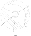
FIG. 4 is a perspective schematic view showing the structure of a support portion of the pressure relief device inFIG. 1 ; -
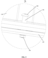
FIG. 5 is a schematic view showing the assembly of a fastening assembly of a pressure relief device in an initial state according to another embodiment of the present application; -
FIG. 6 is a schematic view showing the assembly of the fastening assembly of the pressure relief device inFIG. 5 under an impact; -
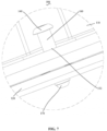
FIG. 7 is a schematic view showing the assembly of a fastening assembly of a pressure relief device in an initial state according to yet another embodiment of the present application; -
FIG. 8 is a schematic view showing the assembly of the fastening assembly of the pressure relief device inFIG. 7 under an impact; -
FIG. 9 is a schematic view showing the assembly of a fastening assembly of a pressure relief device in an initial state according to still another embodiment of the present application; and -
FIG. 10 is a schematic view showing the assembly of the fastening assembly of the pressure relief device inFIG. 9 under an impact. -
Reference numerals: 100 pressure relief device, 110 first housing, 111 through mounting hole, 120 second housing, 130 first locking structure, 131 support portion, 132 stop portion, 133 notch, 134 limit member, 135 retaining ring, 140 second locking structure, 150 locking member, 151 first connecting segment, 152 second connecting segment, 153 screw portion, 154 locking nut, 155 annular mounting groove, 160 first fastener, 170 second fastener. - The realization of the purpose of the present application, functional characteristics and advantages will be further described in conjunction with the embodiments and with reference to the accompanying drawings.
- Technical solutions according to the embodiments of the present application will be described clearly and completely as follows in conjunction with the accompany drawings in the embodiments of the present application. It is obvious that the described embodiments are only a part of the embodiments according to the present application, rather than all of the embodiments. All the other embodiments obtained by those skilled in the art based on the embodiments in the present application without any creative work belong to the scope of protection of the present application.
- It should be noted that, all of the directional indications (such as up, down, left, right, front, back...) in the embodiments of the present application are merely for relative positional relationship, movements, etc. of the assemblies in a certain posture (as shown in the accompany drawings). If the certain posture changes, the directional indication will also change correspondingly.
- In addition, terms such as "first", "second" and the like in the present application are merely for description, and should not be construed as indicating or implying relative importance, or implicitly indicating the number of the technical features. Therefore, the features defined as "first" and "second" may explicitly or implicitly include at least one of these features. In addition, the technical solutions of various embodiments can be combined with each other, but it must be based on the realization of those skilled in the art. When the combination of technical solutions is contradictory or cannot be realized, it should be regarded as not existing, nor within the scope of protection required by the present application.
- A
pressure relief device 100 is provided in the present application, to provide protection for electrical equipment with a high requirement for environment, such as an inverter, a converter, a power supply apparatus or the like. - In the embodiments of the present application, as shown in
FIGS. 1 to 10 , thepressure relief device 100 includes afirst housing 110 and asecond housing 120 being connected to each other in an enclosing manner, and a fastening assembly connecting thefirst housing 110 and thesecond housing 120. Thefirst housing 110 is provided with a throughmounting hole 111, and thesecond housing 120 is provided with a connection hole corresponding to the throughmounting hole 111. The fastening assembly connects the throughmounting hole 111 and the connection hole, where afirst locking structure 130 and asecond locking structure 140 spaced apart from each other are formed by cooperation between the fastening assembly and thefirst housing 110. In an initial state, thefirst locking structure 130 prevents thefirst housing 110 from moving in a direction away from thesecond housing 120. Under an impact of an external force, thefirst locking structure 130 is damaged, and thesecond locking structure 140 stops thefirst housing 110 from moving in the direction away from thesecond housing 120. - The fastening assembly connects the
first housing 110 and thesecond housing 120 by connecting the through mountinghole 111 and the connection hole. Thefirst locking structure 130 and thesecond locking structure 140 spaced apart from each other are formed by cooperation between the fastening assembly and thefirst housing 110. In the initial state, thefirst locking structure 130 is located between the fastening assembly and the through mountinghole 111, and prevents thefirst housing 110 from moving in the direction away from thesecond housing 120, so as to fasten thefirst housing 110 with thesecond housing 120. Under the impact of an external force, due to the impact force, thefirst housing 110 moves away from thesecond housing 120, and thefirst locking structure 130 is damaged. At this time, thesecond locking structure 140 stops thefirst housing 110, to reduce the possibility of thefirst housing 110 being separated from thesecond housing 120. - In an embodiment, an outer diameter of the
second locking structure 140 is larger than a diameter of the through mountinghole 111. Since the diameter of thesecond locking structure 140 is larger than that of the through mountinghole 111, the second fastening assembly abuts against a rim of the through mountinghole 111. Therefore, the through mountinghole 111 can hardly get out of the fastening assembly, such that thesecond locking structure 140 stops the through mountinghole 111. - In an embodiment, the
second housing 120 and thefirst housing 110 are each provided with an avoidance groove, to facilitate dismounting and mounting of the fastening assembly. By providing the avoidance groove on thefirst housing 110, where the avoidance groove extends along a direction away from an axis of the through mountinghole 111, so that mounting and dismounting of the fastening assembly become easier for a user. - In the solutions of the present application, the
first housing 110 and thesecond housing 120 are connected to each other in an enclosing manner, where thefirst housing 110 is provided with the through mountinghole 111, and thesecond housing 120 is provided with the connection hole corresponding to the through mountinghole 111. The fastening assembly connects thefirst housing 110 and thesecond housing 120 through the through mountinghole 111 and the connection hole. Thefirst locking structure 130 and thesecond locking structure 140 spaced apart from each other are formed by cooperation between the fastening assembly and thefirst housing 110. In the initial state, thefirst locking structure 130 is located between the fastening assembly and the through mountinghole 111, and prevents thefirst housing 110 from moving in the direction away from thesecond housing 120, thereby fastening thefirst housing 110 with thesecond housing 120. Under the impact of an external force, due to the impact force, thefirst housing 110 moves away from thesecond housing 120, and thefirst locking structure 130 is damaged; at this time, thesecond locking structure 140 stops thefirst housing 110, to reduce the possibility of thefirst housing 110 being separated from thesecond housing 120, which reduces the possibility that thefirst housing 110, thesecond housing 120, the fastening assembly and the electrical assemblies mounted in thefirst housing 110 and thesecond housing 120 are blasted away due to the impact to cause personal injury, so as to guarantee the safety of equipment and people around, and thus the safety hazards are eliminated. - Please refer to
FIGS. 1 to 4 in conjunction, in an embodiment, thefirst locking structure 130 includes asupport portion 131 provided at the through mountinghole 111 and astop portion 132 provided on the fastening assembly. In the initial state, thestop portion 132 abuts against thesupport portion 131, and under the impact of the external force, thesupport portion 131 is damaged by thestop portion 132. Specifically, since thesupport portion 131 is connected to an inner wall of the through mountinghole 111, and thestop portion 132 is provided on the fastening assembly, thesupport portion 131 is able to prevent the fastening assembly from moving in a direction toward thesecond housing 120, where the fastening assembly passes through an inner side of thesupport portion 131 and is connected to the connection hole. Under the impact of the external force, thesecond housing 120 moves outwards with respect to thefirst housing 110, such that an impact occurs between thestop portion 132 and thesupport portion 131, and thesupport portion 131 is damaged by thestop portion 132 due to the impact, leading to the failure of thefirst locking structure 130. - In this embodiment, the
support portion 131 is integrally formed with thefirst housing 110, which not only reduces the mounting process of thesupport portion 131 and thefirst housing 110, but also decreases the possibility of thesupport portion 131 being separated from thefirst housing 110, thereby improving the structural stability of thefirst housing 110. Certainly, in other embodiments, thesupport portion 131 may be connected to thefirst housing 110 by bonding or clamping. In this embodiment, thestop portion 132 is integrally formed with the fastening assembly, which not only reduces the mounting process of thestop portion 132 and the fastening assembly, but also decreases the possibility of thestop portion 132 being separated from the fastening assembly, thereby improving the structural stability of the fastening assembly. Certainly, in other embodiments, thestop portion 132 may be connected to the fastening assembly by bonding or clamping. - In the solution that the
support portion 131 is provided in the through mountinghole 111, in order to ensure that thesupport portion 131 can fall off smoothly under the impact force, in an embodiment, a thickness of thesupport portion 131 is less than a depth of the through mountinghole 111. Thesupport portion 131 is arranged at an inner side of the through mountinghole 111 in an annular manner, and thestop portion 132 on the fastening assembly abuts against thesupport portion 131. Since the thickness of thesupport portion 131 is less than the depth of the through mountinghole 111, and thesupport portion 131 and thefirst housing 110 are made of the same material, a strength of thesupport portion 131 is lower than a strength of thefirst housing 110, such that when thepressure relief device 100 is under the impact force, thesupport portion 131 is easier to be separated from the through mountinghole 111. In other embodiments, the thickness of thesupport portion 131 may be equal to or larger than the depth of the through mountinghole 111, where thesupport portion 131 and thefirst housing 110 are made of different materials, and the strength of thesupport portion 131 is lower than the strength of thefirst housing 110. - In order to further ensure that the
support portion 131 can fall off smoothly under the impact force, in another embodiment, thesupport portion 131 is provided with at least onenotch 133, and thenotch 133 extends along a radial direction of the through mountinghole 111. Specifically, thesupport portion 131 is provided with at least onenotch 133, i.e. thesupport portion 131 may be provided with onenotch 133 ormultiple notches 133, and thenotch 133 extends along the radial direction of the through mountinghole 111. That is, thesupport portion 131 may be provided with a recessed groove, or may be provided with a cross-shaped groove. Thenotch 133 can cause stress concentration at thenotch 133 of thesupport portion 131, such that thesupport portion 131 is easier to be broken at thenotch 133, which makes it easier for thesupport portion 131 to be separated from the through mountinghole 111. - In an embodiment, the fastening assembly includes a locking
member 150, and the lockingmember 150 includes a first connectingsegment 151 and a second connectingsegment 152, where the first connectingsegment 151 is provided with thestop portion 132 and thesecond locking structure 140, and the second connectingsegment 152 passes through the through mountinghole 111 to be in fixed connection with the connection hole. Specifically, the lockingmember 150 is provided with the first connectingsegment 151 and the second connectingsegment 152, where thesecond locking structure 140 is provided at an end of the first connectingsegment 151 away from the second connectingsegment 152, and the second connectingsegment 152 passes through the through mountinghole 111 to be in fixed connection with the connection hole. The first connectingsegment 151 is further provided with thestop portion 132, and thestop portion 132 acts against thesupport portion 131 to form thefirst locking structure 130, so as to stop thefirst housing 110 in the direction away from thesecond housing 120. - Further, in an embodiment, the
stop portion 132 is a step surface formed on the first connectingsegment 151, and thesupport portion 131 is formed at the inner side of the through mountinghole 111 and extends toward an interior thereof. In the initial state, the step surface abuts against thesupport portion 131. Specifically, thestop portion 132 is the step surface formed on the first connectingsegment 151, and specifically, a diameter of the first connectingsegment 151 is larger than a diameter of the second connectingsegment 152, such that the step surface is formed at a place where the first connectingsegment 151 is in connection with the second connectingsegment 152. Thesupport portion 131 is formed at the inner side of the through mountinghole 111 and extends toward the interior thereof, and the first connectingsegment 151 passes through the through mountinghole 111, such that in the initial state, the step surface abuts against thesupport portion 131, to prevent thefirst housing 110 from moving in the direction away from thesecond housing 120. - As for the connection manner between the locking
member 150 and thesecond housing 120, in an embodiment, the second connectingsegment 152 is provided with ascrew portion 153, and the connection hole is embodied as a threaded hole, where thescrew portion 153 is in threaded connection with the connection hole. Specifically, thescrew portion 153 is formed on the second connectingsegment 152, and the connection hole is embodied as the threaded hole, where thescrew portion 153 is in threaded connection with the connection hole, such that the lockingmember 150 is fixed by threaded connection. This kind of connection manner is simple and easy for mounting. Certainly, in other embodiments, the lockingmember 150 may be fixed with thesecond housing 120 by bonding, clamping or interference fit. - In order to improve the connection strength between the locking
member 150 and thesecond housing 120, in an embodiment, thesecond housing 120 is provided with a mounting protrusion, which extends toward the through mountinghole 111, the connection hole passes through the mounting protrusion, and the lockingmember 150 is connected to thesecond housing 120 through the mounting protrusion. Since the mounting protrusion extending toward the through mountinghole 111 is provided on thesecond housing 120, and the connection hole passes through the mounting protrusion and thesecond housing 120, the lockingmember 150 is connected to thesecond housing 120 through the mounting protrusion, and the lockingmember 150 is in threaded connection with the connection hole, which increases a contact area between thesecond housing 120 and the lockingmember 150, and further improves the connection strength between the lockingmember 150 and thesecond housing 120, such that when thepressure relief device 100 is under the impact force, the lockingmember 150 can hardly be blasted away from thepressure relief device 100. Moreover, in view of the connection strength between thesecond housing 120 and the mounting protrusion, thesecond housing 120 and the mounting protrusion are integrally formed. Certainly, in other embodiments, thesecond housing 120 and the mounting protrusion may be connected by bonding, clamping or interference fit. - As for the connection manner between the locking
member 150 and thesecond housing 120, in another embodiment, referring toFIGS. 1 ,4 ,5 and6 , the second connectingsegment 152 is provided with thescrew portion 153, thescrew portion 153 is arranged passing through the connection hole, and a part of thescrew portion 153 passed through the connection hole is in threaded connection with a lockingnut 154, where the lockingnut 154 abuts against a side of thesecond housing 120 away from thefirst housing 110. Specifically, the second connectingsegment 152 is provided with thescrew portion 153, and thescrew portion 153 passes through the connection hole to be in threaded connection with the lockingnut 154. The lockingnut 154 abuts against the side of thesecond housing 120 away from thefirst housing 110, thus the lockingnut 154 is able to stop the lockingmember 150 from getting away from thesecond housing 120, to reduce the possibility of thefirst housing 110 and thesecond housing 120 being separated under the impact force. - Compared with the solution that the
first locking structure 130 includes the lockingmember 150, in another embodiment, referring toFIGS. 1 ,4 ,7 and8 , the fastening assembly includes afirst fastener 160 and asecond fastener 170, where thefirst fastener 160 is arranged at a side of thefirst housing 110 away from thesecond housing 120, and thefirst fastener 160 is provided with thestop portion 132 and thesecond locking structure 140, and thesecond fastener 170 passes through the connection hole to be in fixed connection with thefirst locking structure 160. Specifically, the fastening assembly includes thefirst fastener 160 and thesecond fastener 170, where thefirst fastener 160 is arranged at the side of thefirst housing 110 away from thesecond housing 120, and thesecond fastener 170 passes through the connection hole and is in fixed connection with thefirst locking structure 160. Thefirst fastener 160 is provided with thestop portion 132 and thesecond locking structure 140. Thesecond locking structure 140 is provided at an end of thefirst fastener 160, and the other end of thefirst fastener 160 is provided with an inner threaded hole. Thesecond fastener 170 is provided with thescrew portion 153, and thescrew portion 153 passes through the connection hole to be in threaded connection with thefirst fastener 160, such that a step surface is formed at a place where thescrew portion 153 is in connection with thefirst fastener 160, to serve as a stopping surface which abuts against thesupport portion 131. A third locking structure is provided on an end of thesecond fastener 170 away from thescrew portion 153, to stop thesecond locking structure 150 from being separated from thesecond housing 120, such that thefirst housing 110 and thesecond housing 120 are fastened. - Compared with the solution that the
first locking structure 130 includes thesupport portion 131 provided in the through mountinghole 111 and thestop portion 132 provided on the fastening assembly, in another embodiment, referring toFIGS. 1 ,9 and10 , thefirst locking structure 130 is embodied as alimit member 134 provided on the fastening assembly. In the initial sate, thelimit member 134 abuts against a rim of the through mountinghole 111, and under the impact of the external force, thelimit member 134 is damaged by the through mountinghole 111. Specifically, thelimit member 134 is arranged on the fastening assembly, and the fastening assembly passes through the through mountinghole 111 and is connected to the connection hole, thelimit member 134 abuts against the rim of the through mountinghole 111, such that the through mountinghole 111 stops the fastening assembly from moving in the direction toward thesecond housing 120 through thelimit member 134. When under the impact of the external force, thelimit member 134 is separated from the fastening assembly due to the impact force, thus thesecond housing 120 moves outwards, the fastening assembly passes through the through mountinghole 111, such that thesecond locking structure 140 abuts against the rim of the through mountinghole 111. Compared with the solution that thesupport portion 131 is provided in the through mountinghole 111, in this solution, only the processing of the fastening assembly is required, which makes the processing easier. - In the solution where the
limit member 134 is provided on the fastening assembly, in an embodiment, thelimit member 134 is embodied as a retainingring 135, and anannular mounting groove 155 is provided on the fastening assembly, where the retainingring 135 is arranged in the annular mountinggroove 155. Specifically, the retainingring 135 is fixed on the fastening assembly, and since the diameter of the through mountinghole 111 is less than an outer diameter of the retainingring 135, the retainingring 135 is able to stop the fastening assembly from moving in the direction toward thesecond housing 120. Further, the retainingring 135 has an open end, such that when thepressure relief device 100 is under the impact force, the retainingring 135 can smoothly fall off from the fastening assembly, which further allows thefirst locking structure 130 to abut against the rim of the through mountinghole 111. In order to facilitate the mounting of the retainingring 135 and the clamping of the retainingring 135 on the fastening assembly, the fastening assembly is provided with the annular mountinggroove 155. The solution that the annular mountinggroove 155 being provided on the fastening assembly facilitates the fixation of the retainingring 135 with the fastening assembly. Moreover, compared with a solution that the retainingring 135 and the fastening assembly are integrally formed, by the connection manner via the annular mountinggroove 155, the retainingring 135 is easier to be separated from the fastening assembly. Certainly, in other embodiments, the retainingring 135 may be fixed to the fastening assembly by bonding or integrated formation. - In the solution where the
limit member 134 is provided on the fastening assembly, in order to facilitate the connection between the fastening assembly and thesecond housing 120, in an embodiment, thescrew portion 153 is formed on the fastening assembly, and the connection hole is embodied as the threaded hole, where thescrew portion 153 is in threaded connection with the connection hole. Specifically, thescrew portion 153 is formed at an end of the fastening assembly away from thesecond locking structure 140, and thescrew portion 153 is in threaded connection with the connection hole, such that the fastening assembly is fixed by threaded connection. This connection manner is simple and easy for mounting. Certainly, in other embodiments, the fastening assembly may be fixed with thesecond housing 120 by bonding, clamping or interference fit. - In another embodiment, referring to
FIGS. 1 ,5 ,9 and10 , the lockingnut 154 may be arranged at a side of thesecond housing 120 away from the fastening assembly, and thescrew portion 153 passes through the connection hole to be in threaded connection with the lockingnut 154, so as to fasten thefirst housing 110 and thesecond housing 120. - In an embodiment, multiple fastening assemblies are mounted on the
pressure relief device 100, where the multiple fastening assemblies are arranged spaced apart from each other. Specifically, the multiple fastening assemblies are mounted on thepressure relief device 100, and correspondingly, thefirst housing 110 and thesecond housing 120 are provided with multiple through mountingholes 111 and multiple connection holes respectively. For thefirst locking structures 130 on the fastening assemblies, all of which may employ the solution that thesupport portion 131 being arranged in the through mountinghole 111 and thestop portion 132 being arranged on the fastening assembly, or all of which may employ the solution that thelimit member 134 being arranged on the fastening assembly, or both of the solutions may be employed at the same time. The connection manner between the fastening assembly and thesecond housing 120 may employ the manner that the fastening assembly being fixed with the connection hole directly, or the manner that the fastening assembly passing through the connection hole to be in threaded connection with the locking nut, or both of the manners may be employed. Or, thefirst housing 110 and thesecond housing 120 may be connected through fixed connection between two fasteners. When fastening assemblies are employed, the impact force can be distributed on multiple screws, to reduce the possibility of the fastening assembly, thefirst housing 110, thesecond housing 120 and electrical assemblies therein being separated from thepressure relief device 100 under the impact force. - Electrical equipment is further provided according to the present application. The electrical equipment includes the
pressure relief device 100, where the specific structure of thepressure relief device 100 is referred to the above embodiments. Since this second subject may employ all of the solutions according to all of the above embodiments, therefore has at least all of the beneficial effects of the solutions in the above embodiments, which will not be described herein. - The embodiments described hereinabove are only preferred embodiments of the present application, and are not intended to limit the scope of the present application. Any equivalent structural modifications based on the description and the accompany drawings of the present application, or direct/indirect utilization in other relevant technical fields, are deemed to fall into the scope of the technical solution of the present application.
Claims (14)
- A pressure relief device, comprising:a first housing and a second housing being connected to each other in an enclosing manner, wherein the first housing is provided with a through mounting hole, and the second housing is provided with a connection hole corresponding to the through mounting hole; anda fastening assembly, which is configured to connect the through mounting hole and the connection hole to fix the first housing with the second housing, wherein a first locking structure and a second locking structure spaced apart from each other are formed by cooperation between the fastening assembly and the first housing; and whereinin an initial state, the first locking structure is configured to prevent the first housing from moving in a direction away from the second housing; and under an impact of an external force, the first locking structure is damaged, and the second locking structure is configured to stop the first housing from moving in the direction away from the second housing.
- The pressure relief device according to claim 1, whereinthe first locking structure comprises a support portion provided at the through mounting hole and a stop portion provided at the fastening assembly; andin the initial state, the stop portion abuts against the support portion; and under the impact of the external force, the support portion is damaged by the stop portion.
- The pressure relief device according to claim 2, wherein the fastening assembly comprises a locking member, the locking member comprises a first connecting segment and a second connecting segment, the stop portion and the second locking structure are formed on the first connecting segment, and the second connecting segment passes through the through mounting hole to be in fixed connection with the connection hole.
- The pressure relief device according to claim 3, wherein the stop portion is a step surface formed on the first connecting segment, and the support portion is formed at an inner side of the through mounting hole and extends toward an interior of the through mounting hole; wherein in the initial state, the step surface abuts against the support portion.
- The pressure relief device according to claim 4, whereina thickness of the support portion is less than a depth of the through mounting hole; and/orthe support portion is provided with at least one notch extending along a radial direction of the through mounting hole.
- The pressure relief device according to claim 4, wherein a screw portion is formed at the second connecting segment, the connection hole is embodied as a threaded hole, and the screw portion is in threaded connection with the connection hole.
- The pressure relief device according to claim 4, whereina screw portion is formed at the second connecting segment, and the screw portion is arranged through the connection hole; and whereina portion of the screw portion passed through the connection hole is in threaded connection with a locking nut, and the locking nut abuts against a side of the second housing away from the first housing.
- The pressure relief device according to claim 2, wherein the fastening assembly comprises a first fastener and a second fastener, the first fastener is arranged at a side of the first housing away from the second housing, the first fastener is provided with the stop portion and the second locking structure, and the second fastener passes through the connection hole to be in fixed connection with the first fastener.
- The pressure relief device according to claim 1, whereinthe first locking structure is a limit member arranged on the fastening assembly; and in the initial state, the limit member abuts against a rim of the through mounting hole;and under the impact of the external force, the limit member is damaged by the through mounting hole.
- The pressure relief device according to claim 9, wherein the limit member is a retaining ring, the fastening assembly is provided with an annular mounting groove, and the retaining ring is mounted in the annular mounting groove.
- The pressure relief device according to claim 9, wherein a screw portion is formed on the fastening assembly, the connection hole is embodied as a threaded hole, and the screw portion is in threaded connection with the connection hole.
- The pressure relief device according to any one of claims 1 to 11, wherein an outer diameter of the second locking structure is larger than a diameter of the through mounting hole.
- The pressure relief device according to claim 1, wherein the number of the fastening assembly is plural, and the plurality of fastening assemblies are arranged on the pressure relief device in a spaced manner.
- Electrical equipment, comprising the pressure relief device according to any one of claims 1 to 13.
Applications Claiming Priority (2)
| Application Number | Priority Date | Filing Date | Title |
|---|---|---|---|
| CN202111556505.2A CN114256748B (en) | 2021-12-17 | 2021-12-17 | Pressure relief devices and electrical equipment |
| PCT/CN2022/096156 WO2023109022A1 (en) | 2021-12-17 | 2022-05-31 | Pressure relief device and electrical equipment |
Publications (2)
| Publication Number | Publication Date |
|---|---|
| EP4451491A1 true EP4451491A1 (en) | 2024-10-23 |
| EP4451491A4 EP4451491A4 (en) | 2026-01-14 |
Family
ID=80792897
Family Applications (1)
| Application Number | Title | Priority Date | Filing Date |
|---|---|---|---|
| EP22905790.6A Pending EP4451491A4 (en) | 2021-12-17 | 2022-05-31 | PRESSURE RELIEF DEVICE AND ELECTRICAL EQUIPMENT |
Country Status (3)
| Country | Link |
|---|---|
| EP (1) | EP4451491A4 (en) |
| CN (1) | CN114256748B (en) |
| WO (1) | WO2023109022A1 (en) |
Families Citing this family (2)
| Publication number | Priority date | Publication date | Assignee | Title |
|---|---|---|---|---|
| CN114256748B (en) * | 2021-12-17 | 2024-08-13 | 阳光电源股份有限公司 | Pressure relief devices and electrical equipment |
| CN222851613U (en) * | 2024-07-23 | 2025-05-09 | 阳光电源股份有限公司 | Energy storage box and electric equipment |
Family Cites Families (19)
| Publication number | Priority date | Publication date | Assignee | Title |
|---|---|---|---|---|
| US3599528A (en) * | 1969-08-21 | 1971-08-17 | Allied Chem | Pressure relief bolt |
| EP0687587A1 (en) * | 1994-06-13 | 1995-12-20 | Technical Products Group Incorporated | Safety pressure vessel system |
| JP3313097B2 (en) * | 1999-11-10 | 2002-08-12 | 永山電子工業株式会社 | Metal fastening members and shell exterior members |
| CA2349262A1 (en) * | 2000-12-27 | 2002-06-27 | S&C Electric Company | Pressure relief arrangement for a housing |
| JP2005244103A (en) * | 2004-02-27 | 2005-09-08 | Kyocera Corp | Enclosure airtight structure |
| CN202308814U (en) * | 2011-11-02 | 2012-07-04 | 北京中纺锐力机电有限公司 | Cabinet door of flame-proof electrical cabinet, and flame-proof electrical cabinet |
| DE102012013325A1 (en) * | 2012-07-06 | 2014-10-30 | Volkswagen Aktiengesellschaft | Joining of components made of different materials by means of a joining aid |
| CN203522008U (en) * | 2013-09-11 | 2014-04-02 | 山东泰开成套电器有限公司 | Novel pressure-releasing device used for switchgear |
| CN205092440U (en) * | 2015-10-29 | 2016-03-16 | 上海天正机电(集团)有限公司 | Pressure release roof for cubical switchboard |
| CN106122547B (en) * | 2016-08-30 | 2018-08-17 | 徐燕 | A kind of venting of dust explosion fastener |
| CN206422403U (en) * | 2017-02-13 | 2017-08-18 | 湖北鄂电德力电气有限公司 | The blast resistance construction of high-tension switch cabinet |
| CN207234370U (en) * | 2017-09-18 | 2018-04-13 | 四川赛康智能科技股份有限公司 | A kind of orientable cable intermediate joint protecting box |
| CN208793417U (en) * | 2018-09-30 | 2019-04-26 | 郑州大学 | An explosion vent bolt system |
| CN209115498U (en) * | 2018-11-09 | 2019-07-16 | 北方特种能源集团有限公司西安庆华公司 | One kind having weak link high intensity blasting bolt |
| CN209855445U (en) * | 2019-03-14 | 2019-12-27 | 北京金风科创风电设备有限公司 | Locking device and electrical cabinet |
| CN110067899B (en) * | 2019-04-25 | 2024-06-07 | 苏州苏明达防爆设备有限公司 | Strong stainless steel explosion-proof flexible connecting pipe |
| CN111503110B (en) * | 2020-04-23 | 2022-05-10 | 河北远东特种门窗集团有限公司 | Explosion venting bolt and mounting method |
| CN212726246U (en) * | 2021-01-29 | 2021-03-16 | 山东万海电气科技有限公司 | Pressure relief device of high-voltage power distribution cabinet |
| CN114256748B (en) * | 2021-12-17 | 2024-08-13 | 阳光电源股份有限公司 | Pressure relief devices and electrical equipment |
-
2021
- 2021-12-17 CN CN202111556505.2A patent/CN114256748B/en active Active
-
2022
- 2022-05-31 WO PCT/CN2022/096156 patent/WO2023109022A1/en not_active Ceased
- 2022-05-31 EP EP22905790.6A patent/EP4451491A4/en active Pending
Also Published As
| Publication number | Publication date |
|---|---|
| CN114256748B (en) | 2024-08-13 |
| EP4451491A4 (en) | 2026-01-14 |
| WO2023109022A1 (en) | 2023-06-22 |
| CN114256748A (en) | 2022-03-29 |
Similar Documents
| Publication | Publication Date | Title |
|---|---|---|
| US20210045254A1 (en) | Loading Assembly | |
| KR960009735B1 (en) | Fasteners for Cable Bushings | |
| EP3671974B1 (en) | Connector | |
| US12272895B2 (en) | Recessed D-subminiature connector assembly with flush mount cover | |
| EP4525566A1 (en) | Case and electrical device | |
| CN114256748B (en) | Pressure relief devices and electrical equipment | |
| EP3698106B1 (en) | Dual wet and dry combination mounting | |
| RU2586988C2 (en) | Fastened structure | |
| US11971065B2 (en) | Nut locking system and electronic device comprising such nut locking system | |
| US20140085785A1 (en) | Electronic device with rubber pads | |
| CN215861289U (en) | Connecting structure | |
| CN112823458B (en) | Cable connector | |
| US20250357685A1 (en) | Terminal block | |
| CN209805547U (en) | Motor casing | |
| CN113483013A (en) | Connecting structure | |
| US20250253633A1 (en) | Cover tabs for electromagnetic compatibility in junction box | |
| CN219553533U (en) | Fastening structure and circuit breaker | |
| US12451642B2 (en) | Sealing installation device and connector assembly | |
| CN222356682U (en) | Explosion-proof boxes, electronic equipment and power systems | |
| KR102753802B1 (en) | Furniture concent for being installed in the proximity of edge | |
| CN222775804U (en) | Cable fixtures and power enclosures | |
| CN223858953U (en) | Motor casting end cover | |
| CN222381527U (en) | Dust cover and photovoltaic inverter | |
| CN218644592U (en) | Hoop with anti-loosening structure | |
| CN214196937U (en) | Rotating shaft assembly for electronic equipment and electronic equipment |
Legal Events
| Date | Code | Title | Description |
|---|---|---|---|
| STAA | Information on the status of an ep patent application or granted ep patent |
Free format text: STATUS: THE INTERNATIONAL PUBLICATION HAS BEEN MADE |
|
| PUAI | Public reference made under article 153(3) epc to a published international application that has entered the european phase |
Free format text: ORIGINAL CODE: 0009012 |
|
| STAA | Information on the status of an ep patent application or granted ep patent |
Free format text: STATUS: REQUEST FOR EXAMINATION WAS MADE |
|
| 17P | Request for examination filed |
Effective date: 20240404 |
|
| AK | Designated contracting states |
Kind code of ref document: A1 Designated state(s): AL AT BE BG CH CY CZ DE DK EE ES FI FR GB GR HR HU IE IS IT LI LT LU LV MC MK MT NL NO PL PT RO RS SE SI SK SM TR |
|
| DAV | Request for validation of the european patent (deleted) | ||
| DAX | Request for extension of the european patent (deleted) | ||
| A4 | Supplementary search report drawn up and despatched |
Effective date: 20251211 |
|
| RIC1 | Information provided on ipc code assigned before grant |
Ipc: H02B 1/26 20060101AFI20251205BHEP Ipc: H01H 9/04 20060101ALI20251205BHEP Ipc: H02B 13/025 20060101ALI20251205BHEP Ipc: H02B 1/28 20060101ALI20251205BHEP |