Pressure relief device of high-voltage power distribution cabinet
Technical Field
The utility model relates to a switch board technical field especially relates to a high voltage distribution cabinet's pressure release lid structure.
Background
The centrally-mounted switch cabinet is called metal armored centrally-mounted withdrawable switch equipment, belongs to a high-voltage distribution device, and is used for receiving and distributing 3.6-12 kV network electric energy and implementing control protection, monitoring and measurement on a power circuit. The central switch cabinet is mainly used for power plants, power transmission of small and medium-sized generators, power receiving and power transmission of secondary substations of power systems, power distribution of industrial and mining enterprises and institutions, starting of large-scale high-voltage motors and the like.
The middle-mounted switch cabinet is usually provided with a pressure relief device, and because the voltage in the switch cabinet is higher and the current is larger, once a fault occurs, a large amount of heat is generated to rapidly expand air, so that the pressure is released through a pressure relief channel, and the switch cabinet can be cracked in serious cases, which is very dangerous.
The existing switch cabinet is usually provided with a rectangular metal top plate at the top of the cabinet, the rectangular metal top plate is fixedly connected with the cabinet by metal bolts or nylon screws, and the switch cabinet has the following defects:
1. when electrical equipment in the cabinet body breaks down, the pressure relief plate is sometimes difficult to open, so that safety accidents are easy to occur, because the voltage in the switch cabinet is higher and the current is larger, the failure can generate more heat, so that the air is rapidly expanded, the pressure is released through the pressure relief channel, and the switch cabinet is cracked in serious cases; or the top plate is easy to separate from the top plate and falls into the cabinet along the pressure relief hole of the top cover to cause short circuit, so that the accident is further expanded; the pressure relief plate or the top plate can fly away from the cabinet to cause injury to other people, which is very dangerous for the equipment and surrounding operators;
2. the top of the existing switch cabinet is generally provided with a rectangular metal top plate which is fixed by nylon screws, when the interior of the cabinet breaks down and is automatically decompressed, the nylon screws are damaged to open the top plate, the process is rapid, the top plate is also easily damaged, and the loss is serious;
3. after the electric equipment in the cabinet body breaks down, the pressure relief channel is open, the electrified body in the cabinet is not shielded, so that great potential safety hazard exists, and the requirement of national standard on the protection level of the cabinet body is not met;
4. after the electric equipment in the cabinet body breaks down, the pressure relief cover deforms seriously, is damaged and lost, cannot restore automatically, causes long maintenance and repair period, is difficult to maintain, has long purchase period, is not beneficial to maintenance, and invisibly increases the operation cost of users.
SUMMERY OF THE UTILITY MODEL
In order to solve the deficiencies in the prior art, the utility model aims to provide a can ensure that the pressure relief board effectively opens and automatic closed high voltage distribution cabinet pressure relief device at the pressure release in-process.
The utility model provides a technical scheme that its technical problem adopted is:
the utility model provides a high voltage distribution cabinet pressure relief device, includes the cabinet body and pressure release board, is equipped with the pressure release mouth on the top surface of the cabinet body, just the pressure release board is located the top surface of the cabinet body and covers and close pressure release mouth, its characterized in that: the utility model discloses a pressure release board, including pressure release board, mounting hole, nylon bolt, hinge, mounting hole, cushion lid, the pressure release board one side is passed through nylon bolt and cabinet body coupling, the opposite side that the pressure release board is relative still pass through the hinge with cabinet body coupling, on the pressure release board in a little bit more than the mounting hole that nylon bolt set up is seted up to nylon bolt's position, and the upper portion of mounting hole is equipped with a laminating at the cushion that the pressure release board surface set up, and the cushion lid closes mounting hole upper portion, just nylon bolt passes cushion and.
One end of each of two sides of the pressure relief plate, which is close to the hinge, is connected with the cabinet body through a limiting part, and the pressure relief plate passes through an opening angle between the limiting part and the top surface of the cabinet body, which is an acute angle.
The limiting part comprises two groups of limiting plates which are movably connected with each other, and the outer ends of the two groups of limiting plates are respectively connected with the cabinet body and the pressure relief plate.
The limiting plates are provided with elongated holes distributed along the length direction of the limiting plates, and the end parts of the limiting plates of the other group are rotatably connected with the elongated holes and arranged in a sliding mode along the length direction of the elongated holes.
The utility model has the advantages that:
1. the mounting structure of hinge direction formula is adopted to pressure release board one side among the device, and the opposite side then adopts the cooperation structure of nylon screw and cushion, utilizes the cushion pressure to consolidate the pressure release board, can make the pressure release lid activate easily at the pressure release in-process, and the pressure release passageway is in time effectually opened, effectively prevents to arouse other incident because of the pressure release trouble, the safety of effective better protection personal equipment.
2. The pressure relief plate can be timely and effectively opened, so that the pressure relief plate and the cabinet body cannot deform due to damage of the pressure relief device, and meanwhile, due to the adoption of a hinge guide type mounting structure, the opening moving direction of the pressure relief plate is ordered in the pressure relief process, and the pressure relief plate and the top plate cabinet body cannot be easily deformed;
3. the installation structure based on hinge direction formula mutually supports with the locating part, can be covered pressure release channel by the pressure release board is automatic after equipment pressure release, accords with cabinet body protection standard.
4. The device improves the optimization to pressure relief device and makes pressure relief device repeatedly use, appears less pressure relief trouble, maintains simply, and use cost is low, reduces because of the hardware damages, the operation cost increase that secondary failure caused, effectively reduces user's operation cost.
Drawings
The present invention will be further explained with reference to the drawings and examples.
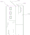
Fig. 1 is a schematic structural diagram of the present invention.
Fig. 2 is a schematic structural view of the top surface of the cabinet and the pressure relief plate (in an open state).
Fig. 3 is a schematic view of a partial structure of the limiting member in fig. 2.
In the figure: the novel multifunctional cabinet comprises a cabinet body 100, a pressure relief opening 101, a pressure relief plate 200, a hinge 300, a limiting piece 400, a first limiting plate 401, a second limiting plate 402, a long hole 403 and a cushion 500.
Detailed Description
The following description is provided for illustrative purposes, and other advantages and features of the present invention will become apparent to those skilled in the art from the following detailed description.
According to the illustrations of fig. 1 to 3: the embodiment provides a high voltage distribution cabinet pressure relief device, including cabinet body 100 and pressure relief board 200, be equipped with pressure relief mouth 101 on the top surface of cabinet body 100, pressure relief mouth 101 is including three rectangle opening, and respectively with the handcart room that corresponds, bus-bar room and cable chamber communicate each other, a pressure relief use for the inside three subchamber of cabinet body 100, and pressure relief board 200 is located the top surface of cabinet body 100, and pressure relief board 200 also is equipped with three groups with three pressure relief mouth 101 one-to-one respectively, simultaneously close corresponding pressure relief mouth 101 by pressure relief board 200 lid, make pressure relief mouth 101 hide, and this pressure relief board 200 can normally open at the pressure relief in-process, and can also rely on gravity to fall down and close corresponding pressure relief mouth 101 once more by the lid after the pressure relief is ended, wherein describe as follows to the concrete implementation mode of pressure relief board 200.
The pressure release board 200 is the apron structure that matches with pressure release 101 shape, and the left side of pressure release board 200 is connected with the cabinet body 100 through two sets of nylon bolts, the right side that pressure release board 200 is relative still through two sets of hinges 300 with be connected with the cabinet body 100, the position that is close to the right-hand member of both sides around pressure release board 200 still respectively through locating part 400 with the cabinet body 100 is connected, wherein:
in the structure, the pressure relief plate 200 is fixed by the conventional nylon bolt instead of fixing the pressure relief plate 200 by the way of matching the nylon bolt with the cushion 500, the cushion 500 is more easily deformed in the pressure relief process, so that the pressure relief plate 200 is more easily separated from the cabinet body 100 by the matching structure of the cushion 500 and the mounting hole, thereby timely and effectively opening the pressure relief plate 200 and realizing the pressure relief operation;
the limiting member 400 comprises two groups of limiting plates movably connected with each other, the outer ends of the two groups of limiting plates are respectively connected and fixed with the cabinet 100 and the pressure relief plate 200, wherein a group of first limiting plates 401 at the lower part is provided with strip holes 403 distributed along the length direction thereof, the strip holes 403 are vertically distributed, the bottom end of the first limiting plate 401 is connected and fixed with the cabinet 100, the bottom end of the other group of second limiting plates 402 is rotatably connected with the strip holes 403 through a rotating shaft and is arranged in a sliding manner along the length direction of the strip holes 403, meanwhile, the top end of the second limiting plate 402 is rotatably connected with the side surface of the pressure relief plate 200, through the assembling effect of the limiting member 400, in the pressure relief process, the limiting member is mainly dependent on the movement of the second limiting plate 402 at the upper part and plays a limiting role, the pressure relief plate 200 is acute angle through the opening angle between the limiting member 400 and, thereby make pressure release board 200 in the pressure release process after opening, set up towards pressure release mouth 101 one side slope all the time, so after the pressure release is accomplished, the air pressure in the cabinet body 100 is normal, and pressure release board 200 can rely on self gravity to fall to pressure release mouth 101 one side this moment to close pressure release mouth 101 lid once more, thereby hide pressure release mouth 101, ensured the inside equipment safety of cabinet body 100.
The limiting member 400 adopted in the above structure is not limited to the structure provided in this embodiment, and can also achieve the above functions for the simple structure components such as the mature metal chains and the mature metal wires in the prior art, and the equivalent limiting effect can be achieved only by fixing the two ends of the metal plate, the metal chains and the metal wires respectively, but the requirements on the strength requirements, the flexibility and other properties of the metal plate, the metal chains and the metal wires are higher.
The above is only the preferred embodiment of the present invention, as long as the preferred embodiment is realized by the same means, the objective technical solution of the present invention all belongs to the protection scope of the present invention.