EP4451418A1 - Batterieverwaltungsvorrichtung und betriebsverfahren dafür - Google Patents
Batterieverwaltungsvorrichtung und betriebsverfahren dafür Download PDFInfo
- Publication number
- EP4451418A1 EP4451418A1 EP23812041.4A EP23812041A EP4451418A1 EP 4451418 A1 EP4451418 A1 EP 4451418A1 EP 23812041 A EP23812041 A EP 23812041A EP 4451418 A1 EP4451418 A1 EP 4451418A1
- Authority
- EP
- European Patent Office
- Prior art keywords
- battery
- value
- banks
- impedance
- battery banks
- Prior art date
- Legal status (The legal status is an assumption and is not a legal conclusion. Google has not performed a legal analysis and makes no representation as to the accuracy of the status listed.)
- Pending
Links
Images


Classifications
-
- G—PHYSICS
- G01—MEASURING; TESTING
- G01R—MEASURING ELECTRIC VARIABLES; MEASURING MAGNETIC VARIABLES
- G01R31/00—Arrangements for testing electric properties; Arrangements for locating electric faults; Arrangements for electrical testing characterised by what is being tested not provided for elsewhere
- G01R31/36—Arrangements for testing, measuring or monitoring the electrical condition of accumulators or electric batteries, e.g. capacity or state of charge [SoC]
- G01R31/389—Measuring internal impedance, internal conductance or related variables
-
- H—ELECTRICITY
- H01—ELECTRIC ELEMENTS
- H01M—PROCESSES OR MEANS, e.g. BATTERIES, FOR THE DIRECT CONVERSION OF CHEMICAL ENERGY INTO ELECTRICAL ENERGY
- H01M10/00—Secondary cells; Manufacture thereof
- H01M10/42—Methods or arrangements for servicing or maintenance of secondary cells or secondary half-cells
- H01M10/48—Accumulators combined with arrangements for measuring, testing or indicating the condition of cells, e.g. the level or density of the electrolyte
-
- G—PHYSICS
- G01—MEASURING; TESTING
- G01R—MEASURING ELECTRIC VARIABLES; MEASURING MAGNETIC VARIABLES
- G01R19/00—Arrangements for measuring currents or voltages or for indicating presence or sign thereof
- G01R19/165—Indicating that current or voltage is either above or below a predetermined value or within or outside a predetermined range of values
- G01R19/16528—Indicating that current or voltage is either above or below a predetermined value or within or outside a predetermined range of values using digital techniques or performing arithmetic operations
-
- G—PHYSICS
- G01—MEASURING; TESTING
- G01R—MEASURING ELECTRIC VARIABLES; MEASURING MAGNETIC VARIABLES
- G01R27/00—Arrangements for measuring resistance, reactance, impedance, or electric characteristics derived therefrom
- G01R27/02—Measuring real or complex resistance, reactance, impedance, or other two-pole characteristics derived therefrom, e.g. time constant
- G01R27/08—Measuring resistance by measuring both voltage and current
-
- G—PHYSICS
- G01—MEASURING; TESTING
- G01R—MEASURING ELECTRIC VARIABLES; MEASURING MAGNETIC VARIABLES
- G01R31/00—Arrangements for testing electric properties; Arrangements for locating electric faults; Arrangements for electrical testing characterised by what is being tested not provided for elsewhere
- G01R31/36—Arrangements for testing, measuring or monitoring the electrical condition of accumulators or electric batteries, e.g. capacity or state of charge [SoC]
- G01R31/382—Arrangements for monitoring battery or accumulator variables, e.g. SoC
- G01R31/3842—Arrangements for monitoring battery or accumulator variables, e.g. SoC combining voltage and current measurements
-
- G—PHYSICS
- G01—MEASURING; TESTING
- G01R—MEASURING ELECTRIC VARIABLES; MEASURING MAGNETIC VARIABLES
- G01R31/00—Arrangements for testing electric properties; Arrangements for locating electric faults; Arrangements for electrical testing characterised by what is being tested not provided for elsewhere
- G01R31/36—Arrangements for testing, measuring or monitoring the electrical condition of accumulators or electric batteries, e.g. capacity or state of charge [SoC]
- G01R31/392—Determining battery ageing or deterioration, e.g. state of health
-
- G—PHYSICS
- G01—MEASURING; TESTING
- G01R—MEASURING ELECTRIC VARIABLES; MEASURING MAGNETIC VARIABLES
- G01R31/00—Arrangements for testing electric properties; Arrangements for locating electric faults; Arrangements for electrical testing characterised by what is being tested not provided for elsewhere
- G01R31/36—Arrangements for testing, measuring or monitoring the electrical condition of accumulators or electric batteries, e.g. capacity or state of charge [SoC]
- G01R31/396—Acquisition or processing of data for testing or for monitoring individual cells or groups of cells within a battery
-
- H—ELECTRICITY
- H01—ELECTRIC ELEMENTS
- H01M—PROCESSES OR MEANS, e.g. BATTERIES, FOR THE DIRECT CONVERSION OF CHEMICAL ENERGY INTO ELECTRICAL ENERGY
- H01M10/00—Secondary cells; Manufacture thereof
- H01M10/42—Methods or arrangements for servicing or maintenance of secondary cells or secondary half-cells
- H01M10/425—Structural combination with electronic components, e.g. electronic circuits integrated to the outside of the casing
-
- H—ELECTRICITY
- H01—ELECTRIC ELEMENTS
- H01M—PROCESSES OR MEANS, e.g. BATTERIES, FOR THE DIRECT CONVERSION OF CHEMICAL ENERGY INTO ELECTRICAL ENERGY
- H01M10/00—Secondary cells; Manufacture thereof
- H01M10/42—Methods or arrangements for servicing or maintenance of secondary cells or secondary half-cells
- H01M10/48—Accumulators combined with arrangements for measuring, testing or indicating the condition of cells, e.g. the level or density of the electrolyte
- H01M10/482—Accumulators combined with arrangements for measuring, testing or indicating the condition of cells, e.g. the level or density of the electrolyte for several batteries or cells simultaneously or sequentially
-
- H—ELECTRICITY
- H01—ELECTRIC ELEMENTS
- H01M—PROCESSES OR MEANS, e.g. BATTERIES, FOR THE DIRECT CONVERSION OF CHEMICAL ENERGY INTO ELECTRICAL ENERGY
- H01M10/00—Secondary cells; Manufacture thereof
- H01M10/42—Methods or arrangements for servicing or maintenance of secondary cells or secondary half-cells
- H01M10/48—Accumulators combined with arrangements for measuring, testing or indicating the condition of cells, e.g. the level or density of the electrolyte
- H01M10/486—Accumulators combined with arrangements for measuring, testing or indicating the condition of cells, e.g. the level or density of the electrolyte for measuring temperature
-
- B—PERFORMING OPERATIONS; TRANSPORTING
- B60—VEHICLES IN GENERAL
- B60Y—INDEXING SCHEME RELATING TO ASPECTS CROSS-CUTTING VEHICLE TECHNOLOGY
- B60Y2200/00—Type of vehicle
- B60Y2200/90—Vehicles comprising electric prime movers
- B60Y2200/91—Electric vehicles
-
- H—ELECTRICITY
- H01—ELECTRIC ELEMENTS
- H01M—PROCESSES OR MEANS, e.g. BATTERIES, FOR THE DIRECT CONVERSION OF CHEMICAL ENERGY INTO ELECTRICAL ENERGY
- H01M10/00—Secondary cells; Manufacture thereof
- H01M10/42—Methods or arrangements for servicing or maintenance of secondary cells or secondary half-cells
- H01M10/425—Structural combination with electronic components, e.g. electronic circuits integrated to the outside of the casing
- H01M2010/4271—Battery management systems including electronic circuits, e.g. control of current or voltage to keep battery in healthy state, cell balancing
-
- H—ELECTRICITY
- H01—ELECTRIC ELEMENTS
- H01M—PROCESSES OR MEANS, e.g. BATTERIES, FOR THE DIRECT CONVERSION OF CHEMICAL ENERGY INTO ELECTRICAL ENERGY
- H01M2220/00—Batteries for particular applications
- H01M2220/20—Batteries in motive systems, e.g. vehicle, ship, plane
-
- Y—GENERAL TAGGING OF NEW TECHNOLOGICAL DEVELOPMENTS; GENERAL TAGGING OF CROSS-SECTIONAL TECHNOLOGIES SPANNING OVER SEVERAL SECTIONS OF THE IPC; TECHNICAL SUBJECTS COVERED BY FORMER USPC CROSS-REFERENCE ART COLLECTIONS [XRACs] AND DIGESTS
- Y02—TECHNOLOGIES OR APPLICATIONS FOR MITIGATION OR ADAPTATION AGAINST CLIMATE CHANGE
- Y02E—REDUCTION OF GREENHOUSE GAS [GHG] EMISSIONS, RELATED TO ENERGY GENERATION, TRANSMISSION OR DISTRIBUTION
- Y02E60/00—Enabling technologies; Technologies with a potential or indirect contribution to GHG emissions mitigation
- Y02E60/10—Energy storage using batteries
-
- Y—GENERAL TAGGING OF NEW TECHNOLOGICAL DEVELOPMENTS; GENERAL TAGGING OF CROSS-SECTIONAL TECHNOLOGIES SPANNING OVER SEVERAL SECTIONS OF THE IPC; TECHNICAL SUBJECTS COVERED BY FORMER USPC CROSS-REFERENCE ART COLLECTIONS [XRACs] AND DIGESTS
- Y02—TECHNOLOGIES OR APPLICATIONS FOR MITIGATION OR ADAPTATION AGAINST CLIMATE CHANGE
- Y02T—CLIMATE CHANGE MITIGATION TECHNOLOGIES RELATED TO TRANSPORTATION
- Y02T10/00—Road transport of goods or passengers
- Y02T10/60—Other road transportation technologies with climate change mitigation effect
- Y02T10/70—Energy storage systems for electromobility, e.g. batteries
-
- Y—GENERAL TAGGING OF NEW TECHNOLOGICAL DEVELOPMENTS; GENERAL TAGGING OF CROSS-SECTIONAL TECHNOLOGIES SPANNING OVER SEVERAL SECTIONS OF THE IPC; TECHNICAL SUBJECTS COVERED BY FORMER USPC CROSS-REFERENCE ART COLLECTIONS [XRACs] AND DIGESTS
- Y02—TECHNOLOGIES OR APPLICATIONS FOR MITIGATION OR ADAPTATION AGAINST CLIMATE CHANGE
- Y02T—CLIMATE CHANGE MITIGATION TECHNOLOGIES RELATED TO TRANSPORTATION
- Y02T10/00—Road transport of goods or passengers
- Y02T10/60—Other road transportation technologies with climate change mitigation effect
- Y02T10/72—Electric energy management in electromobility
Definitions
- Embodiments disclosed herein relate to a battery management apparatus and an operating method thereof.
- An electric vehicle is supplied with electricity from outside to charge a battery, and then a motor is driven by a voltage charged in the battery to obtain power.
- the battery of the electric vehicle may have heat generated therein by chemical reaction occurring in a process of charging and discharging electricity, and the heat may impair performance and lifetime of the battery.
- a battery management apparatus or a battery management system (BMS) that monitors and controls temperature, voltage, and current of the battery is driven to diagnose the state of the battery.
- a conventional battery management apparatus has a difficulty in detecting a battery cell where heat is generated inside a battery bank unless a thermistor is attached to each battery bank including a plurality of battery cells to measure a temperature.
- the conventional battery management apparatus may detect a heat-generated battery cell inside the battery by measuring a direct current resistance (DCR) of each battery bank, but large equipment is used in measurement of the direct current resistance, such that measurement of the direct current resistance may be possible only when the battery bank is being charged and measurement may be impossible during the use of the battery bank, degrading effectiveness.
- DCR direct current resistance
- Embodiments disclosed herein aim to provide a battery management apparatus and an operating method thereof, that may determine whether an abnormal battery cell exists in a battery bank based on an impedance of a battery bank, obtained by measuring a current and a voltage of the battery bank.
- a battery management apparatus includes a switch connected to a plurality of battery banks including a plurality of battery cells and a controller configured to apply a control signal for repeatedly turning on or off the switch, measuring a voltage value and a current value of each of the plurality of battery banks, and determine whether a plurality of battery cells included in each of the plurality of battery banks are abnormal based on an alternating current impedance of each of the plurality of battery banks calculated based on the voltage value and the current value.
- the controller may be further configured to obtain a real value and an imaginary value of the voltage value and the current value by performing Fourier transform on the voltage value and the current value of each of the plurality of battery banks.
- the controller may be further configured to obtain an imaginary value of an impedance of each of the plurality of battery banks based on the real value and the imaginary value of the voltage value and the current value.
- the controller may be further configured to determine that a heat-generated battery cell exists in at least any one of battery cells inside any one of the plurality of battery banks when an imaginary value of an impedance of any one of the plurality of battery banks exceeds a previously stored threshold value.
- the controller may be further configured to determine that a heat-generated battery cell exists in at least any one of battery cells inside any one of the plurality of battery banks when an imaginary value of an impedance of any one of the plurality of battery banks falls beyond a threshold error range of an imaginary value of an impedance of a battery bank serially connected to any one of the plurality of battery banks.
- An operating method of a battery management apparatus includes applying a control signal for repeatedly turning on or off a switch connected to a plurality of battery banks including a plurality of battery cells, measuring a voltage value and a current value of each of the plurality of battery banks, calculating an alternating current impedance of each of the plurality of battery banks based on the voltage value and the current value, and determining whether a plurality of battery cells included in each of the plurality of battery banks are abnormal based on an alternating current impedance of each of the plurality of battery banks.
- the calculating of the alternating current impedance of each of the plurality of battery banks based on the voltage value and the current value may include obtaining a real value and an imaginary value of the voltage value and the current value by performing Fourier transform on the voltage value and the current value of each of the plurality of battery banks.
- the calculating of the alternating current impedance of each of the plurality of battery banks based on the voltage value and the current value may include obtaining an imaginary value of an impedance of each of the plurality of battery banks based on the real value and the imaginary value of the voltage value and the current value.
- the determining of whether the plurality of battery cells included in each of the plurality of battery banks are abnormal based on an alternating current impedance of each of the plurality of battery banks may include determining that a heat-generated battery cell exists in at least any one of battery cells inside any one of the plurality of battery banks when an imaginary value of an impedance of any one of the plurality of battery banks exceeds a previously stored threshold value.
- the determining of whether the plurality of battery cells included in each of the plurality of battery banks are abnormal based on an alternating current impedance of each of the plurality of battery banks may include determining that a heat-generated battery cell exists in at least any one of battery cells inside any one of the plurality of battery banks when an imaginary value of an impedance of any one of the plurality of battery banks falls beyond a threshold error range of an imaginary value of an impedance of a battery bank serially connected to any one of the plurality of battery banks.
- the battery management apparatus and the operating method thereof may be determined whether an abnormal battery cell exists inside a battery bank based on an impedance of the battery bank measured by a current and a voltage of the battery bank.
- terms such as first, second, A, B, (a), (b), etc. may be used. These terms are used merely for distinguishing one component from another component and do not limit the component to the essence, sequence, order, etc., of the component.
- the terms used herein, including technical and scientific terms, have the same meanings as terms that are generally understood by those skilled in the art, as long as the terms are not differently defined.
- the terms defined in a generally used dictionary should be interpreted as having the same meanings as the contextual meanings of the relevant technology and should not be interpreted as having ideal or exaggerated meanings unless they are clearly defined in the present document.
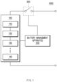
- FIG. 1 illustrates a battery pack according to an embodiment disclosed herein.
- a battery pack 1000 may include a battery module 100, a battery management apparatus 200, and a relay 300.
- the battery module 100 may include a plurality of battery banks 110, 120, 130, and 140. Although the plurality of battery banks are illustrated as four in FIG. 1 , the present disclosure is not limited thereto, and the battery module 100 may include n battery banks (n is a natural number equal to or greater than 2).
- the battery module 100 may supply power to a target device (not shown). To this end, the battery module 100 may be electrically connected to the target device.
- the target device may include an electrical, electronic, or mechanical device that operates by receiving power from the battery pack 1000 including the plurality of battery banks 110, 120, 130, and 140, and the target device may be, for example, an electric vehicle (EV) or an energy storage system (ESS), but is not limited thereto.
- EV electric vehicle
- ESS energy storage system
- the plurality of battery banks 110, 120, 130, and 140 may include a plurality of battery cells.
- the battery cell which is a basic unit of a battery available by charging and discharging electrical energy, may be a lithium ion (Li-ion) battery, an Li-ion polymer battery, a nickel-cadmium (Ni-Cd) battery, a nickel hydrogen (Ni-MH) battery, etc., and are not limited thereto.
- the plurality of battery cells included in each of the plurality of battery banks 110, 120, 130, and 140 may be connected in parallel to each other.
- the battery module 100 may be configured in plural according to an embodiment.
- the battery management apparatus (a battery management system (BMS)) 200 may predict a life (a state of health (SoH)) of the plurality of battery banks 110, 120, 130, and 140 based on temperature and voltage data of the plurality of battery banks 110, 120, 130, and 140.
- the battery management apparatus 200 may remove noise from battery data of the plurality of battery banks 110, 120, 130, and 140 and predict a life (SoH) of the plurality of battery banks 110, 120, 130, and 140 for each of temperature and charge/discharge rate of a battery based on the noise-removed data.
- the battery management apparatus 200 may manage and/or control a state and/or an operation of the battery module 100.
- the battery management apparatus 200 may manage and/or control the states and/or operations of the plurality of battery banks 110, 120, 130, and 140 included in the battery module 100.
- the battery management apparatus 200 may manage charging and/or discharging of the battery module 100.
- the battery management apparatus 200 may monitor a voltage, a current, a temperature, etc., of the battery module 100 and/or each of the plurality of battery banks 110, 120, 130, and 140 included in the battery module 100.
- a sensor or various measurement modules for monitoring performed by the battery management system which are not shown, may be additionally installed in the battery module 100, a charging/discharging path, any position of the battery module 100, etc.
- the battery management apparatus 200 may calculate a parameter indicating a state of the battery module 100, e.g., a state of charge (SoC), a SoH, etc., based on a measurement value such as monitored voltage, current, temperature, etc.
- SoC state of charge
- SoH SoH
- the battery management apparatus 200 may control an operation of the relay 300. For example, the battery management apparatus 200 may short-circuit the relay 300 to supply power to the target device. The battery management apparatus 200 may short-circuit the relay 300 when a charging device is connected to the battery pack 1000.
- the battery management apparatus 200 may calculate a cell balancing time of each of the plurality of battery banks 110, 120, 130, and 140.
- the cell balancing time may be defined as a time required for balancing of the battery cell.
- the battery management apparatus 200 may calculate a cell balancing time based on an SoC, a battery capacity, and a balancing efficiency of each of the plurality of battery banks 110, 120, 130, and 140.
- the battery management apparatus 200 may calculate an impedance of a battery bank based on data of various factors changing with deterioration of the battery.
- the battery management apparatus 200 may calculate an imaginary value of an impedance of the plurality of battery banks 110, 120, 130, and 140 based on data of various factors changing with deterioration of the plurality of battery banks 110, 120, 130, and 140 to determine whether an abnormal battery cell exists inside the plurality of battery banks 110, 120, 130, and 140.
- the imaginary value of the impedance of the battery may be an index indicating whether heat is generated in the battery in an abnormal state when compared to a normal state of the battery bank.
- the imaginary value of the impedance of the normal battery bank and the imaginary value of the impedance of the abnormal battery bank may be distinguished.
- the battery management apparatus 200 may determine whether an abnormal battery cell exists inside the plurality of battery banks 110, 120, 130, and 140 based on a voltage and a current of each of the plurality of battery banks 110, 120, 130, and 140.
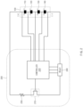
- FIG. 2 is a circuit diagram illustrating an implementation example of a battery management apparatus according to an embodiment disclosed herein.
- the battery management apparatus 200 may include a switch 210, a controller 220, a first resistor 230, and a shunt resistor 240.
- the switch 210 may be connected to a plurality of battery banks including a plurality of battery cells.
- the switch 210 may include, for example, a field effect transistor (FET).
- FET field effect transistor
- the switch 210 may receive a control signal for repeatedly turning on and off the switch 210 from the controller 220.
- the switch 210 may be repeatedly turned on or off based on the control signal received from the controller 220.
- the switch 210 may be repeatedly turned on or off and deliver a current in an alternating current waveform to the plurality of battery banks 110, 120, 130, and 140.
- the first resistor 230 may control a flow of current inside the battery management apparatus 200 to allow an internal circuit of the battery management apparatus 200 to smoothly operate.
- the controller 220 may determine whether an abnormal battery cell exists inside the plurality of battery banks 110, 120, 130, and 140 based on battery data of the plurality of battery banks 110, 120, 130, and 140. More specifically, the controller 220 may determine whether a heat-generated battery cell exists inside the plurality of battery banks 110, 120, 130, and 140 based on battery data of the plurality of battery banks 110, 120, 130, and 140.
- the controller 220 may generate the control signal for repeatedly turning on and off the switch 210 and apply the control signal to the switch 210.
- the controller 220 may measure a voltage value and a current value of each of the plurality of battery banks 110, 120, 130, and 140 having received the current in the alternating current waveform based on a switching operation of the switch 210.
- the controller 220 may measure a current value of each of the plurality of battery banks 110, 120, 130, and 140 by using the shunt resistor 240.
- the shunt resistor 240 may be a resistor mainly used for current measurement as a shunt resistor and may have a very low resistance value.
- the shunt resistor 240 may measure a current value of each of the plurality of battery banks 110, 120, 130, and 140, and the controller 220 may obtain a current value of each of the plurality of battery banks 110, 120, 130, and 140 from the shunt resistor 240.
- FIG. 3 is a graph showing a change in a current value and a voltage value of a battery bank with respect to a flow of a time frequency, according to an embodiment disclosed herein.
- current of each of the plurality of battery banks 110, 120, 130, and 140 having received a current in the alternating current waveform may be measured in the form of a square wave based on the control signal of the controller 220.
- a measured waveform of a voltage value of each of the plurality of battery banks 110, 120, 130, and 140 over time may shake.
- the controller 220 may determine whether a plurality of battery cells included in each of the plurality of battery banks 110, 120, 130, and 140 are abnormal, based on an alternating current impedance of each of the plurality of battery banks 110, 120, 130, and 140 calculated based on a voltage value and a current value of each of the plurality of battery banks 110, 120, 130, and 140.
- FIG. 4A is a graph showing a result of Fourier transform of a current value of a battery bank with respect to a flow of a time frequency, according to an embodiment disclosed herein.
- FIG. 4B is a graph showing a result of Fourier transform of a voltage value of a battery bank with respect to a flow of a time frequency, according to an embodiment disclosed herein.
- the controller 220 may perform Fourier transform (FT) on a voltage value and a current value of each of the plurality of battery banks 110, 120, 130, and 140 to obtain a real value and an imaginary value of the voltage value and the current value of each of the plurality of battery banks 110, 120, 130, and 140.
- Fourier transform may mean transform to decompose a function with respect to time or space into a time or space frequency component.
- the controller 220 may decompose a voltage value and a current value of each of the plurality of battery banks 110, 120, 130, and 140 over time into a time frequency component to convert the same into a complex number including a real value and an imaginary value. That is, the controller 220 may derive a waveform of a real value and an imaginary value of a voltage value and a current value of each of the plurality of battery banks 110, 120, 130, and 140 over time.
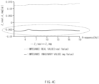
- FIG. 4C is a graph showing a real value and an imaginary value of an impedance of a battery bank with respect to a flow of a time frequency, according to an embodiment disclosed herein.
- the controller 220 may obtain an imaginary value of an impedance of each of the plurality of battery banks 110, 120, 130, and 140 based on a real value and an imaginary value of a voltage value and a current value of each of the plurality of battery banks 110, 120, 130, and 140. More specifically, the controller 220 may calculate an impedance based on the Ohm's Law used in the RLC current circuit.
- 'V' means a voltage
- 'I' means a current
- 'R' means a resistance
- 'Z' means an impedance.
- the impedance is a value that disturbs the flow of current when a voltage is applied to a circuit.
- the impedance value may be indicated by a ratio of a voltage V to a current I of an alternating current circuit in which the impedance has a value of a phase unlike a resistor used in the direct current circuit.
- the imaginary value of the impedance of the plurality of battery banks 110, 120, 130, and 140 may change with a temperature of the battery bank.
- the imaginary value of the impedance of the battery bank may have a constant value in spite of the change in the time frequency, but may change with the temperature.
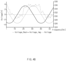
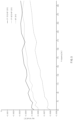
- FIG. 5 is a graph showing a change in an imaginary value of an impedance a battery bank with respect to a change in a time frequency, according to an embodiment disclosed herein.
- the graph shown in FIG. 5 means a change of an imaginary value of an impedance of a battery bank including 6 battery cells 6P connected in parallel.
- a graph shown as a dotted line at the bottom may show a change of the imaginary value of the impedance of the battery bank measured when all of the 6 battery cells are at 20 °C.
- the graph shown as a dotted line in the middle may show a change of the imaginary value of the impedance of the battery bank measured when one battery cell 1P is at 60 °C and the other 5 battery cells 5P are at 20 °C.
- the graph shown as a solid line may show a change of the imaginary value of the impedance of the battery bank measured when one battery cell 1P is at 70 °C and the other 5 battery cells 5P are at 20 °C.
- the controller 220 may diagnose a temperature change of a plurality of battery cells from a change of an imaginary value of an impedance of a plurality of battery banks.
- the imaginary value of the alternating current impedance of the battery bank when heat generation occurs in one or more battery cell inside the battery bank may be distinguished from an imaginary value of an alternating current impedance of a battery bank including normal battery cells.
- the controller 220 may determine that heat generation occurs in any one of the plurality of battery cells inside the battery bank based on the imaginary value of the impedance of the battery bank.
- the controller 220 may determine that a heat-generated battery cell exists in at least any one of battery cells inside any one of the plurality of battery banks 110, 120, 130, and 140.
- the controller 220 may determine that a heat-generated battery cell exists in at least any one of battery cells inside any one of the plurality of battery banks 110, 120, 130, and 140.
- the battery management apparatus 200 may determine whether an abnormal battery cell exists inside a battery bank based on an impedance of the battery bank measured by a current and a voltage of the battery bank.
- the battery management apparatus 200 may previously detect an abnormal battery cell inside a battery bank during an operation of the battery bank to prevent thermal runaway of the battery bank in advance.
- the battery bank When the abnormal battery cell is detected using a direct current resistance meter of an existing battery bank, the battery bank needs to be charged and discharged with a large current of 1C or more, a large equipment such as a cycler that is a large-size current charger is required, but the battery management apparatus 200 may generate an alternating current waveform through switching and apply the alternating current waveform to the battery bank, removing a need for a large-size equipment and thus reducing a cost.
- FIG. 6 is a flowchart showing an operating method of a battery management apparatus, according to an embodiment disclosed herein.
- an operating method of a battery management apparatus may include operation S101 of applying a control signal for repeatedly turning on or off the switch 210 connected to the plurality of battery banks 110, 120, 130, and 140 including a plurality of battery cells, operation S102 of measuring a voltage value and a current value of each of the plurality of battery banks 110, 120, 130, and 140, operation S103 of calculating an alternating current impedance of each of the plurality of battery banks 110, 120, 130, and 140 based on the voltage value and the current value, and operation S104 of determining whether the plurality of battery cells included in each of the plurality of battery banks 110, 120, 130, and 140 are abnormal based on the alternating current impedance of each of the plurality of battery banks 110, 120, 130, and 140.
- the switch 210 may receive a control signal for repeatedly turning on and off the switch 210 from the controller 220.
- the switch 210 may be connected to a plurality of battery banks including a plurality of battery cells.
- the switch 210 may include, for example, an FET.
- the switch 210 may be repeatedly turned on or off based on the control signal received from the controller 220.
- the switch 210 may be repeatedly turned on or off and deliver a current in an alternating current waveform to the plurality of battery banks 110, 120, 130, and 140.
- the controller 220 may generate the control signal for repeatedly turning on and off the switch 210 and apply the control signal to the switch 210.
- the controller 220 may measure a voltage value and a current value of each of the plurality of battery banks 110, 120, 130, and 140 having received the current in the alternating current waveform based on a switching operation of the switch 210.
- the controller 220 may perform Fourier transform on a voltage value and a current value of each of the plurality of battery banks 110, 120, 130, and 140 to obtain a real value and an imaginary value of the voltage value and the current value of each of the plurality of battery banks 110, 120, 130, and 140.
- Fourier transform may mean transform to decompose a function with respect to time or space into a time or space frequency component.
- the controller 220 may decompose a voltage value and a current value of each of the plurality of battery banks 110, 120, 130, and 140 over time into a time frequency component to convert the same into a complex number including a real value and an imaginary value.
- the controller 220 may derive a waveform of a real value and an imaginary value of a voltage value and a current value of each of the plurality of battery banks 110, 120, 130, and 140 over time.
- the controller 220 may obtain an imaginary value of an impedance of each of the plurality of battery banks 110, 120, 130, and 140 based on a real value and an imaginary value of a voltage value and a current value of each of the plurality of battery banks 110, 120, 130, and 140. In operation S103, the controller 220 may calculate an impedance based on the Ohm's Law used in the RLC current circuit.
- the controller 220 may diagnose a temperature change of a plurality of battery cells from a change of an imaginary value of an impedance of a plurality of battery cells.
- the imaginary value of the alternating current impedance when heat generation occurs in one or more battery cell inside the battery bank may be distinguished from an imaginary value of an alternating current impedance of a battery bank including normal battery cells.
- the controller 220 may determine that heat generation occurs in any one of the plurality of battery cells inside the battery bank based on the imaginary value of the impedance of the battery bank.
- the controller 220 may determine that a heat-generated battery cell exists in at least any one of battery cells inside any one of the plurality of battery banks 110, 120, 130, and 140.
- the controller 220 may determine that a heat-generated battery cell exists in at least any one of battery cells inside any one of the plurality of battery banks 110, 120, 130, and 140.
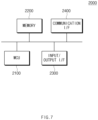
- FIG. 6 is a block diagram showing a hardware configuration of a computing system to implement a battery management apparatus according to an embodiment disclosed herein.
- a computing system 2000 may include an MCU 2100, a memory 2200, an input/output I/F 2300, and a communication I/F 2400.
- the MCU 2100 may be a processor that executes various programs (e.g., an impedance calculation program of a battery bank, etc.) stored in the memory 2200, processes various data through these programs, and perform the above-described functions of the battery management apparatus 200 shown in FIG. 1 .
- programs e.g., an impedance calculation program of a battery bank, etc.
- the memory 2200 may store various programs regarding operations of the battery management apparatus 200. Moreover, the memory 2200 may store operation data of the battery management apparatus 200.
- the memory 2200 may be provided in plural, depending on a need.
- the memory 2200 may be volatile memory or non-volatile memory.
- RAM random access memory
- DRAM dynamic RAM
- SRAM static RAM
- ROM read only memory
- PROM programmable ROM
- EAROM electrically alterable ROM
- EPROM erasable PROM
- EEPROM electrically erasable PROM
- flash memory etc.
- the above-listed examples of the memory 2200 are merely examples and are not limited thereto.
- the input/output I/F 2300 may provide an interface for transmitting and receiving data by connecting an input device (not shown) such as a keyboard, a mouse, a touch panel, etc., and an output device such as a display (not shown), etc., to the MCU 2100.
- an input device such as a keyboard, a mouse, a touch panel, etc.
- an output device such as a display (not shown), etc.
- the communication I/F 2400 which is a component capable of transmitting and receiving various data to and from a server, may be various devices capable of supporting wired or wireless communication.
- a program for resistance measurement and abnormality diagnosis of the battery cell or various data may be transmitted and received to and from a separately provided external server through the communication I/F 2400.
Landscapes
- Engineering & Computer Science (AREA)
- Manufacturing & Machinery (AREA)
- Chemical & Material Sciences (AREA)
- Chemical Kinetics & Catalysis (AREA)
- Electrochemistry (AREA)
- General Chemical & Material Sciences (AREA)
- Physics & Mathematics (AREA)
- General Physics & Mathematics (AREA)
- Microelectronics & Electronic Packaging (AREA)
- Secondary Cells (AREA)
- Tests Of Electric Status Of Batteries (AREA)
- Charge And Discharge Circuits For Batteries Or The Like (AREA)
Applications Claiming Priority (2)
| Application Number | Priority Date | Filing Date | Title |
|---|---|---|---|
| KR1020220064229A KR20230164461A (ko) | 2022-05-25 | 2022-05-25 | 배터리 관리 장치 및 그것의 동작 방법 |
| PCT/KR2023/006433 WO2023229267A1 (ko) | 2022-05-25 | 2023-05-11 | 배터리 관리 장치 및 그것의 동작 방법 |
Publications (2)
| Publication Number | Publication Date |
|---|---|
| EP4451418A1 true EP4451418A1 (de) | 2024-10-23 |
| EP4451418A4 EP4451418A4 (de) | 2025-06-11 |
Family
ID=88919560
Family Applications (1)
| Application Number | Title | Priority Date | Filing Date |
|---|---|---|---|
| EP23812041.4A Pending EP4451418A4 (de) | 2022-05-25 | 2023-05-11 | Batterieverwaltungsvorrichtung und betriebsverfahren dafür |
Country Status (6)
| Country | Link |
|---|---|
| US (1) | US20250116717A1 (de) |
| EP (1) | EP4451418A4 (de) |
| JP (1) | JP2025503928A (de) |
| KR (1) | KR20230164461A (de) |
| CN (1) | CN118541847A (de) |
| WO (1) | WO2023229267A1 (de) |
Families Citing this family (2)
| Publication number | Priority date | Publication date | Assignee | Title |
|---|---|---|---|---|
| DE102019133921A1 (de) * | 2019-12-11 | 2021-06-17 | Bayerische Motoren Werke Aktiengesellschaft | Verfahren, Vorrichtung, System, Elektrofahrzeug, Computerprogramm und Speichermedium zum Laden oder Entladen einer Zelle eines elektrischen Energiespeichers |
| KR20250088213A (ko) * | 2023-12-08 | 2025-06-17 | 주식회사 엘지에너지솔루션 | 배터리 진단 장치 및 그것의 동작 방법 |
Family Cites Families (16)
| Publication number | Priority date | Publication date | Assignee | Title |
|---|---|---|---|---|
| JPH08250159A (ja) * | 1995-03-08 | 1996-09-27 | Nippon Telegr & Teleph Corp <Ntt> | Ni−Cd電池の劣化状態検知方法 |
| KR100546246B1 (ko) * | 2003-04-23 | 2006-01-26 | 주식회사 파워트론 | 축전지 시스템의 열화진단 시스템 |
| JP4645382B2 (ja) * | 2005-09-20 | 2011-03-09 | トヨタ自動車株式会社 | バッテリ状態検知装置、バッテリ状態検知方法 |
| KR20100121354A (ko) * | 2009-05-08 | 2010-11-17 | 삼성전자주식회사 | 연료 전지의 열화를 진단하는 방법 및 장치 |
| KR101416400B1 (ko) * | 2012-12-11 | 2014-08-07 | 현대자동차 주식회사 | 연료 전지 스택의 고장 진단 방법 및 그 장치 |
| KR101572650B1 (ko) * | 2013-02-19 | 2015-12-04 | 주식회사 엘지화학 | 배터리 뱅크의 불균형 진단 장치 및 방법 |
| KR101646854B1 (ko) * | 2014-12-15 | 2016-08-09 | 현대오트론 주식회사 | 연료전지 스택 임피던스 측정 방법 및 이를 실행하는 장치 |
| PL3455917T3 (pl) * | 2016-05-13 | 2022-06-13 | Vito Nv | Sposób i urządzenie modułowego systemu zarządzania dla ogniw magazynowania energii |
| US10481214B2 (en) * | 2017-01-30 | 2019-11-19 | Infineon Technologies Ag | Battery temperature detection |
| CN112313521B (zh) * | 2018-06-27 | 2023-06-13 | 新唐科技日本株式会社 | 电池监视装置、集成电路以及电池监视系统 |
| JP7153196B2 (ja) * | 2018-12-26 | 2022-10-14 | トヨタ自動車株式会社 | 電池特性評価装置、および電池特性評価方法 |
| JP7172838B2 (ja) * | 2019-04-26 | 2022-11-16 | 株式会社デンソー | 電池監視装置 |
| CN111537904A (zh) * | 2020-04-09 | 2020-08-14 | 苏州湛云科技有限公司 | 一种基于交流阻抗虚部的锂离子电池寿命估计方法 |
| DE102020110466A1 (de) * | 2020-04-17 | 2021-10-21 | Volkswagen Aktiengesellschaft | Verfahren zur Bestimmung eines Zustands mindestens einer Zelle einer Batterie und ein Datenverarbeitungssystem |
| KR102913156B1 (ko) | 2020-11-11 | 2026-01-14 | 삼성전자 주식회사 | 송수신부 공급 전압을 캘리브레이션하는 통신 장치 및 이의 동작 방법 |
| CN113447828B (zh) * | 2021-06-21 | 2022-10-14 | 中山大学 | 一种基于贝叶斯神经网络的锂电池温度估计方法及系统 |
-
2022
- 2022-05-25 KR KR1020220064229A patent/KR20230164461A/ko active Pending
-
2023
- 2023-05-11 JP JP2024543545A patent/JP2025503928A/ja active Pending
- 2023-05-11 US US18/729,838 patent/US20250116717A1/en active Pending
- 2023-05-11 WO PCT/KR2023/006433 patent/WO2023229267A1/ko not_active Ceased
- 2023-05-11 CN CN202380016854.6A patent/CN118541847A/zh active Pending
- 2023-05-11 EP EP23812041.4A patent/EP4451418A4/de active Pending
Also Published As
| Publication number | Publication date |
|---|---|
| KR20230164461A (ko) | 2023-12-04 |
| JP2025503928A (ja) | 2025-02-06 |
| US20250116717A1 (en) | 2025-04-10 |
| CN118541847A (zh) | 2024-08-23 |
| EP4451418A4 (de) | 2025-06-11 |
| WO2023229267A1 (ko) | 2023-11-30 |
Similar Documents
| Publication | Publication Date | Title |
|---|---|---|
| US12188986B2 (en) | Apparatus and method for diagnosing a battery | |
| EP4451418A1 (de) | Batterieverwaltungsvorrichtung und betriebsverfahren dafür | |
| US20250012862A1 (en) | Battery capacity prediction apparatus and operating method thereof | |
| US20240410952A1 (en) | Battery management apparatus and operating method thereof | |
| KR20230055178A (ko) | 배터리의 전류 센서 이상 진단 장치 및 방법 | |
| KR20250111280A (ko) | 배터리 데이터 관리 장치 및 그것의 동작 방법 | |
| KR102886638B1 (ko) | 배터리 수명 예측 장치 및 그것의 동작 방법 | |
| EP4660652A1 (de) | Batteriedatenverwaltungsvorrichtung und betriebsverfahren dafür | |
| US20240356346A1 (en) | Battery management apparatus and operating method thereof | |
| EP4365613B1 (de) | Batteriepack und betriebsverfahren dafür | |
| EP4564026A1 (de) | Batterieverwaltungssystem und betriebsverfahren dafür | |
| EP4567447A1 (de) | Batterieverwaltungsvorrichtung und betriebsverfahren dafür | |
| EP4657100A1 (de) | Batterieverwaltungsvorrichtung und betriebsverfahren dafür | |
| EP4607219A1 (de) | Batterieverwaltungsvorrichtung und betriebsverfahren dafür | |
| EP4425199B1 (de) | Batteriedatenverwaltungsvorrichtung und betriebsverfahren | |
| EP4675291A1 (de) | Batterieverwaltungsvorrichtung und betriebsverfahren dafür | |
| US20250298085A1 (en) | Impedance Measurement System And Operating Method Thereof | |
| EP4671791A1 (de) | Batterieverwaltungsvorrichtung und betriebsverfahren dafür | |
| Surya | Comprehensive Review on Algorithms used in Battery Management System for Automotive Applications | |
| EP4650803A1 (de) | Batteriediagnosevorrichtung und betriebsverfahren dafür | |
| KR20240171900A (ko) | 배터리 상태 예측 장치 및 그것의 동작 방법 | |
| EP4671790A1 (de) | Batterieverwaltungsvorrichtung und betriebsverfahren dafür | |
| KR20240037104A (ko) | 배터리 관리 장치 및 그것의 동작 방법 | |
| KR20230020279A (ko) | 배터리 관리 장치 및 그것의 동작 방법 |
Legal Events
| Date | Code | Title | Description |
|---|---|---|---|
| STAA | Information on the status of an ep patent application or granted ep patent |
Free format text: STATUS: THE INTERNATIONAL PUBLICATION HAS BEEN MADE |
|
| PUAI | Public reference made under article 153(3) epc to a published international application that has entered the european phase |
Free format text: ORIGINAL CODE: 0009012 |
|
| STAA | Information on the status of an ep patent application or granted ep patent |
Free format text: STATUS: REQUEST FOR EXAMINATION WAS MADE |
|
| 17P | Request for examination filed |
Effective date: 20240718 |
|
| AK | Designated contracting states |
Kind code of ref document: A1 Designated state(s): AL AT BE BG CH CY CZ DE DK EE ES FI FR GB GR HR HU IE IS IT LI LT LU LV MC ME MK MT NL NO PL PT RO RS SE SI SK SM TR |
|
| A4 | Supplementary search report drawn up and despatched |
Effective date: 20250513 |
|
| RIC1 | Information provided on ipc code assigned before grant |
Ipc: G01R 27/08 20060101ALI20250507BHEP Ipc: G01R 19/165 20060101ALI20250507BHEP Ipc: G01R 31/389 20190101ALI20250507BHEP Ipc: H01M 10/48 20060101ALI20250507BHEP Ipc: H01M 10/42 20060101AFI20250507BHEP |
|
| DAV | Request for validation of the european patent (deleted) | ||
| DAX | Request for extension of the european patent (deleted) | ||
| GRAP | Despatch of communication of intention to grant a patent |
Free format text: ORIGINAL CODE: EPIDOSNIGR1 |
|
| STAA | Information on the status of an ep patent application or granted ep patent |
Free format text: STATUS: GRANT OF PATENT IS INTENDED |