EP4451384A1 - Negativelektrodenzusammensetzung, negativelektrode für lithiumsekundärbatterie damit und lithiumsekundärbatterie mit negativelektrode - Google Patents
Negativelektrodenzusammensetzung, negativelektrode für lithiumsekundärbatterie damit und lithiumsekundärbatterie mit negativelektrode Download PDFInfo
- Publication number
- EP4451384A1 EP4451384A1 EP23868606.7A EP23868606A EP4451384A1 EP 4451384 A1 EP4451384 A1 EP 4451384A1 EP 23868606 A EP23868606 A EP 23868606A EP 4451384 A1 EP4451384 A1 EP 4451384A1
- Authority
- EP
- European Patent Office
- Prior art keywords
- negative electrode
- active material
- silicon
- conductive material
- weight
- Prior art date
- Legal status (The legal status is an assumption and is not a legal conclusion. Google has not performed a legal analysis and makes no representation as to the accuracy of the status listed.)
- Pending
Links
Images
Classifications
-
- H—ELECTRICITY
- H01—ELECTRIC ELEMENTS
- H01M—PROCESSES OR MEANS, e.g. BATTERIES, FOR THE DIRECT CONVERSION OF CHEMICAL ENERGY INTO ELECTRICAL ENERGY
- H01M4/00—Electrodes
- H01M4/02—Electrodes composed of, or comprising, active material
-
- H—ELECTRICITY
- H01—ELECTRIC ELEMENTS
- H01M—PROCESSES OR MEANS, e.g. BATTERIES, FOR THE DIRECT CONVERSION OF CHEMICAL ENERGY INTO ELECTRICAL ENERGY
- H01M10/00—Secondary cells; Manufacture thereof
- H01M10/05—Accumulators with non-aqueous electrolyte
- H01M10/052—Li-accumulators
- H01M10/0525—Rocking-chair batteries, i.e. batteries with lithium insertion or intercalation in both electrodes; Lithium-ion batteries
-
- H—ELECTRICITY
- H01—ELECTRIC ELEMENTS
- H01M—PROCESSES OR MEANS, e.g. BATTERIES, FOR THE DIRECT CONVERSION OF CHEMICAL ENERGY INTO ELECTRICAL ENERGY
- H01M4/00—Electrodes
- H01M4/02—Electrodes composed of, or comprising, active material
- H01M4/13—Electrodes for accumulators with non-aqueous electrolyte, e.g. for lithium-accumulators; Processes of manufacture thereof
- H01M4/131—Electrodes based on mixed oxides or hydroxides, or on mixtures of oxides or hydroxides, e.g. LiCoOx
-
- H—ELECTRICITY
- H01—ELECTRIC ELEMENTS
- H01M—PROCESSES OR MEANS, e.g. BATTERIES, FOR THE DIRECT CONVERSION OF CHEMICAL ENERGY INTO ELECTRICAL ENERGY
- H01M4/00—Electrodes
- H01M4/02—Electrodes composed of, or comprising, active material
- H01M4/13—Electrodes for accumulators with non-aqueous electrolyte, e.g. for lithium-accumulators; Processes of manufacture thereof
- H01M4/134—Electrodes based on metals, Si or alloys
-
- H—ELECTRICITY
- H01—ELECTRIC ELEMENTS
- H01M—PROCESSES OR MEANS, e.g. BATTERIES, FOR THE DIRECT CONVERSION OF CHEMICAL ENERGY INTO ELECTRICAL ENERGY
- H01M4/00—Electrodes
- H01M4/02—Electrodes composed of, or comprising, active material
- H01M4/36—Selection of substances as active materials, active masses, active liquids
- H01M4/38—Selection of substances as active materials, active masses, active liquids of elements or alloys
- H01M4/386—Silicon or alloys based on silicon
-
- H—ELECTRICITY
- H01—ELECTRIC ELEMENTS
- H01M—PROCESSES OR MEANS, e.g. BATTERIES, FOR THE DIRECT CONVERSION OF CHEMICAL ENERGY INTO ELECTRICAL ENERGY
- H01M4/00—Electrodes
- H01M4/02—Electrodes composed of, or comprising, active material
- H01M4/36—Selection of substances as active materials, active masses, active liquids
- H01M4/48—Selection of substances as active materials, active masses, active liquids of inorganic oxides or hydroxides
- H01M4/483—Selection of substances as active materials, active masses, active liquids of inorganic oxides or hydroxides for non-aqueous cells
-
- H—ELECTRICITY
- H01—ELECTRIC ELEMENTS
- H01M—PROCESSES OR MEANS, e.g. BATTERIES, FOR THE DIRECT CONVERSION OF CHEMICAL ENERGY INTO ELECTRICAL ENERGY
- H01M4/00—Electrodes
- H01M4/02—Electrodes composed of, or comprising, active material
- H01M4/36—Selection of substances as active materials, active masses, active liquids
- H01M4/48—Selection of substances as active materials, active masses, active liquids of inorganic oxides or hydroxides
- H01M4/485—Selection of substances as active materials, active masses, active liquids of inorganic oxides or hydroxides of mixed oxides or hydroxides for inserting or intercalating light metals, e.g. LiTi2O4 or LiTi2OxFy
-
- H—ELECTRICITY
- H01—ELECTRIC ELEMENTS
- H01M—PROCESSES OR MEANS, e.g. BATTERIES, FOR THE DIRECT CONVERSION OF CHEMICAL ENERGY INTO ELECTRICAL ENERGY
- H01M4/00—Electrodes
- H01M4/02—Electrodes composed of, or comprising, active material
- H01M4/62—Selection of inactive substances as ingredients for active masses, e.g. binders, fillers
- H01M4/624—Electric conductive fillers
- H01M4/625—Carbon or graphite
-
- H—ELECTRICITY
- H01—ELECTRIC ELEMENTS
- H01M—PROCESSES OR MEANS, e.g. BATTERIES, FOR THE DIRECT CONVERSION OF CHEMICAL ENERGY INTO ELECTRICAL ENERGY
- H01M4/00—Electrodes
- H01M4/02—Electrodes composed of, or comprising, active material
- H01M2004/021—Physical characteristics, e.g. porosity, surface area
-
- H—ELECTRICITY
- H01—ELECTRIC ELEMENTS
- H01M—PROCESSES OR MEANS, e.g. BATTERIES, FOR THE DIRECT CONVERSION OF CHEMICAL ENERGY INTO ELECTRICAL ENERGY
- H01M4/00—Electrodes
- H01M4/02—Electrodes composed of, or comprising, active material
- H01M2004/026—Electrodes composed of, or comprising, active material characterised by the polarity
- H01M2004/027—Negative electrodes
-
- Y—GENERAL TAGGING OF NEW TECHNOLOGICAL DEVELOPMENTS; GENERAL TAGGING OF CROSS-SECTIONAL TECHNOLOGIES SPANNING OVER SEVERAL SECTIONS OF THE IPC; TECHNICAL SUBJECTS COVERED BY FORMER USPC CROSS-REFERENCE ART COLLECTIONS [XRACs] AND DIGESTS
- Y02—TECHNOLOGIES OR APPLICATIONS FOR MITIGATION OR ADAPTATION AGAINST CLIMATE CHANGE
- Y02E—REDUCTION OF GREENHOUSE GAS [GHG] EMISSIONS, RELATED TO ENERGY GENERATION, TRANSMISSION OR DISTRIBUTION
- Y02E60/00—Enabling technologies; Technologies with a potential or indirect contribution to GHG emissions mitigation
- Y02E60/10—Energy storage using batteries
Definitions
- the present application relates to a negative electrode composition, a negative electrode for a lithium secondary battery including the same, and a lithium secondary battery including a negative electrode.
- a secondary battery is a representative example of an electrochemical device that utilizes such electrochemical energy, and the range of use thereof tends to be gradually expanding.
- lithium secondary batteries having high energy density and voltage, long cycle life, and low self-discharging rate have been commercialized and widely used.
- research is being actively conducted on a method for manufacturing a high-density electrode having a higher energy density per unit volume as an electrode for such a high-capacity lithium secondary battery.
- a secondary battery in general, includes a positive electrode, a negative electrode, an electrolyte, and a separator.
- the negative electrode includes a negative electrode active material for intercalating and deintercalating lithium ions to and from the positive electrode, and silicon-based particles having a high discharge capacity may be used as the negative electrode active material.
- Patent Literature 1 Japanese Patent Application Publication No. 2009-080971
- the present application relates to a negative electrode composition, a negative electrode for a lithium secondary battery including the same, and a lithium secondary battery including a negative electrode.
- Another exemplary embodiment of the present invention provides a negative electrode for a lithium secondary battery including a negative electrode current collector layer; and a negative electrode active material layer including the negative electrode composition according to the present application formed on one surface or both surfaces of the negative electrode current collector layer.
- a lithium secondary battery including a positive electrode; the negative electrode for a lithium secondary battery according to the present application; a separator provided between the positive electrode and the negative electrode; and an electrolyte.
- the negative electrode composition according to an exemplary embodiment of the present invention uses the grain silicon-based active material within a specific range for increase in energy density to fabricate a negative electrode.
- the planar conductive material and the linear conductive material are used to greatly improve the electrical connectivity between the silicon-based active materials, resulting in preventing the electrical isolation phenomenon, which may occur when charging/discharging the negative electrode to which the silicon-based active material is applied, to improve the life of the negative electrode.
- particulate conductive material In the case of negative electrodes for which existing carbon-based active materials are used, a small amount of particulate conductive material is used as the negative electrode conductive material. However, if such a particulate conductive material is applied to the silicon-based active material of the present invention, it is difficult to implement sufficient cycle performance. If an excessive amount of particulate conductive material is included, there is room for improvement in life performance, but problems of increases in slurry viscosity and amount of gas generation at high temperatures due to the high specific surface area occur.
- the main feature of the negative electrode composition according to the present application is that the negative electrode conductive material having specific composition and content as described above is applied without using the particulate conductive material, leading to the construction of a system that can be applied together with the silicon-based active material with a high energy density.
- 'p to q' means a range of 'p or more and q or less'.
- the “specific surface area” is measured by the BET method, and specifically, is calculated from a nitrogen gas adsorption amount at a liquid nitrogen temperature (77K) by using BELSORP-mini II available from BEL Japan, Inc. That is, in the present application, the BET specific surface area may refer to the specific surface area measured by the above measurement method.
- Dn refers to a particle diameter distribution, and refers to a particle diameter at the n% point in the cumulative distribution of the number of particles according to the particle diameter. That is, D50 is a particle diameter (average particle diameter) at the 50% point in the cumulative distribution of the number of particles according to the particle diameter, D90 is a particle diameter at the 90% point in the cumulative distribution of the number of particles according to the particle diameter, and D10 is a particle diameter at the 10% point in the cumulative distribution of the number of particles according to the particle diameter. Meanwhile, the particle diameter distribution may be measured using a laser diffraction method.
- the resultant dispersion is introduced into a commercially available laser diffraction particle size measurement apparatus (for example, Microtrac S3500) in which a difference in a diffraction pattern according to the particle size is measured, when a laser beam passes through particles, and then a particle size distribution is calculated.
- a laser diffraction particle size measurement apparatus for example, Microtrac S3500
- a polymer includes a certain monomer as a monomer unit
- the description "a polymer includes a certain monomer as a monomer unit” means that the monomer participates in a polymerization reaction and is included as a repeating unit in the polymer.
- this is interpreted as the same as that the polymer includes a monomer as a monomer unit.
- a weight-average molecular weight (Mw) and a number-average molecular weight (Mn) are polystyrene converted molecular weights measured by gel permeation chromatography (GPC) while employing, as a standard material, a monodispersed polystyrene polymer (standard sample) having various degrees of polymerization commercially available for measuring a molecular weight.
- GPC gel permeation chromatography
- a molecular weight refers to a weight-average molecular weight unless particularly described otherwise.
- An exemplary embodiment of the present specification provides a negative electrode composition including a silicon-based active material; a negative electrode conductive material; and a negative electrode binder, wherein the silicon-based active material has a crystal grain size of 200 nm or less, and wherein the negative electrode conductive material includes a planar conductive material and a linear conductive material.
- pure silicon (Si) particles may be used as a silicon-based active material.
- the silicon-based active material may include a metal impurity, and in this case, the impurity is metal that may be generally included in the silicon-based active material, and specifically, a content thereof may be 0.1 part by weight or less on the basis of 100 parts by weight of the silicon-based active material.
- the capacity of the silicon-based active material is significantly higher than that of a graphite-based active material that is typically used, so that there have been more attempts to apply the same.
- the volume expansion rate of the silicon-based active material during charging/discharging is high, so that, for example, only a small amount thereof is mixed and used with a graphite-based active material.
- the negative electrode composition according to the present invention includes a silicon-based active material whose crystal grain size satisfies a range described below and also includes specific planar conductive material and linear conductive material, thereby improving the life performance of the negative electrode and reducing an amount of gas generation at high temperatures.
- the crystal grain size of the silicon-based active material may be 200 nm or less.
- the crystal grain size of the silicon-based active material may be 10 nm or greater and 150 nm or less.
- the crystal grain size of the silicon-based active material may be 200 nm or less, preferably 130 nm or less, more preferably 110 nm or less, still more preferably 100 nm or less, specifically 95 nm or less, and more specifically 91 nm or less.
- the crystal grain size of the silicon-based active material may have a range of 10 nm or greater, and preferably 15 nm or greater or 30 nm or greater.
- the silicon-based active material has the crystal grain size described above, and the crystal grain size of the silicon-based active material may be controlled by changing a process condition in a manufacturing process.
- the crystal grain boundaries are widely distributed, and thus, the lithium ions can be uniformly intercalated during intercalating of lithium ions, thereby reducing the stress applied during intercalating of lithium ions into the silicon particles, and accordingly, mitigating breakage of the particles.
- characteristics capable of improving the life stability of the negative electrode are obtained.
- the crystal grain size exceeds the above range, the crystal grain boundaries within the particles are narrowly distributed, and in this case, lithium ions are non-uniformly intercalated into the particles, leading to large stress during the intercalating of ions, and accordingly, breakage of particles.
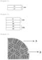
- FIG. 3 is an enlarged view of a silicon-based active material according to an exemplary embodiment of the present application.
- the silicon-based active material 1 is composed of a plurality of crystal structures 2, and in this case, it can be confirmed that the crystal structure has a crystal grain distribution of 1 nm or greater and 200 nm or less.
- a space between crystal structures may be defined as a crystal grain boundary.
- the crystal structure can be expressed as crystal grains.
- the negative electrode active material in which the silicon-based active material includes a crystal structure having a crystal grain distribution of 1 nm or greater and 200 nm or less, and an area ratio of the crystal structure based on a total area of the silicon-based active material is 5% or less.
- the area ratio of the crystal structure based on the total area of the silicon-based active material may be 5% or less, or 3% or less, and 0.1% or greater.
- the silicon-based active material according to the present application has a crystal grain size of 200 nm or less, is formed so that the size of one crystal structure is small, and may satisfy the above area ratio. Accordingly, the distribution of the crystal grain boundaries may be widened, and accordingly, the above-described effects may be exhibited.
- the negative electrode active material in which the number of the crystal structures included in the silicon-based active material is 20 or more.
- the number of crystal structures included in the silicon-based active material may satisfy a range of 20 or more, 30 or more, or 35 or more, and 60 or less or 50 or less.
- the silicon-based active material when the crystal grain size of the silicon-based active material satisfies the above range and the number of crystal structures satisfies the above range, the silicon-based active material itself has strength within an appropriate range. Therefore, when such a silicon-based active material is included in an electrode, flexibility can be imparted, and volume expansion can be effectively suppressed.
- the crystal grain refers to a crystal particle in a metal or material, which is a collection of microscopically irregular shapes, and the crystal grain size may mean a diameter of the observed crystal grain particle. That is, in the present application, the crystal grain size means a size of a domain sharing the same crystal direction in a particle, and has a different concept from a particle size or a size of a particle diameter expressing a size of a material.
- the crystal grain size can be calculated as a value of full width at half maximum (FWHM) through XRD analysis.
- the remaining values except L are measured through XRD analysis of the silicon-based active material, and the crystal grain size can be measured through the Debey-Scherrer equation showing that the FWHM and the crystal grain size are in inverse ratio.
- the Debey-Scherrer equation is as shown in Equation 1-1 below.
- FWHM K ⁇ / LCos ⁇ in Equation 1-1
- L is a crystal grain size
- K is a constant
- ⁇ is a Bragg angle
- ⁇ is a wavelength of X-ray.
- the shapes of the crystal grains are diverse and can be measured in three dimensions.
- the size of the crystal grain can be measured by a generally used circle method or diameter measurement method, but the present invention is not limited thereto.
- the circle method is a method in which a circle with a predetermined diameter is drawn on a micrograph of a target particle, and then an average area of crystal grains is calculated by the number of crystal grains in the circle and the number of crystal grains laid across the boundary line, and the average area can be calculated by Equation 1-3 below.
- Fm Fk*10 6 / 0.67 n + z V 2 ⁇ m 2
- Equation 1-3 Fm is an average particle area
- Fk is a measurement area on the photograph
- z is the number of particles in a circle
- n is the number of particles laid across the circle
- V is a magnification of a microscope.
- the silicon-based active material whose specific surface area is 0.25 m 2 /g or greater may be included.
- the silicon-based active material may have a specific surface area of 0.25 m 2 /g or greater, preferably 0.28 m 2 /g or greater, and more preferably 0.30 m 2 /g or greater, specifically 0.31 m 2 /g or greater, and more specifically 0.32 m 2 /g or greater.
- the silicon-based active material may satisfy a range of a specific surface area of 3 m 2 /g or less, preferably 2.5 m 2 /g or less, and more preferably 2.2 m 2 /g or less.
- the specific surface area may be measured according to DIN 66131 (using nitrogen).
- the negative electrode active material may include a silicon-based active material having a specific surface area of 0.30 m 2 /g or greater and 4.00 m 2 /g or less.
- the silicon-based active material may have a specific surface area of 0.30 m 2 /g or greater, preferably 0.31 m 2 /g or greater, and more preferably 0.32 m 2 /g or greater.
- the silicon-based active material may satisfy a range of a specific surface area of 4.00 m 2 /g or less, preferably 2.50 m 2 /g or less, and more preferably 2.20 m 2 /g or less.
- the silicon-based active material has the specific surface area described above, and the specific surface area of the silicon-based active material may be controlled by changing a process condition of a manufacturing process and a growth condition of the silicon-based active material. That is, when the negative electrode active material is manufactured using the manufacturing method according to the present application, the rough surface results in a larger specific surface area, as compared with particles with the same particle size. In this case, the above range is satisfied, and thus, the bonding force with the binder increases, leading to reduction in cracks of an electrode due to repeating charge and discharge cycles.
- the lithium ions can be uniformly intercalated during intercalation of lithium ions, resulting in reduction in stress applied during intercalation of lithium ions into the silicon particles, and accordingly, reduction in breakage of the particles.
- the specific surface area is less than the above range, the surface is formed smooth even with the same particle size, resulting in a decrease in the bonding force with the binder, and cracks of the electrode.
- lithium ions are non-uniformly intercalated into the particles, resulting in an increase in the stress due to the ion intercalation, and breakage of particles.
- the silicon-based active material may satisfy a range in Equation 2-1 below. X1/Y1 ⁇ 0 .960 in Equation 2-1,
- Equation 2-1 The measurement of Equation 2-1 above may be performed using a particle shape analyzer.
- the silicon-based active material according to the present application may be scattered on a glass plate through air injection, and then a shape of 10,000 silicon-based active material particles in a photograph obtained by capturing a shadow image of the scattered silicon-based active material particles may be measured.
- Equation 2-1 is a value expressing an average of 10,000 particles.
- Equation 2-1 according to the present application can be measured from the above image, and Equation 2-1 can be expressed as sphericity (circularity) of the silicon-based active material. The sphericity may also be expressed by Equation [4 ⁇ *actual area of silicon-based active material/(circumference) 2 ].
- the sphericity of the silicon-based active material may be, for example, 0.960 or less, for example, 0.957 or less.
- the sphericity of the silicon-based active material may be 0.8 or higher, for example, 0.9 or higher, specifically 0.93 or higher, more specifically 0.94 or higher, for example, 0.941 or higher.
- the silicon-based active material may satisfy a range in Equation 2-2 below. X2/Y2 ⁇ 0 .996 in Equation 2-2,
- Equation 2-2 The measurement of Equation 2-2 above may be performed using a particle shape analyzer.
- the silicon-based active material according to the present application may be scattered on a glass plate through air injection, and then a shape of 10,000 silicon-based active material particles in a photograph obtained by capturing a shadow image of the scattered silicon-based active material particles may be measured.
- Equation 2-2 is a value expressing an average of 10,000 particles. Equation 2-2 according to the present application can be measured from the above image, and Equation 2-2 can be expressed as convexity of the silicon-based active material.
- a range of X2/Y2 ⁇ 0.996, preferably X2/Y2 ⁇ 0.995 may be satisfied, and a range of 0.8 ⁇ X2/Y2, preferably 0.9 ⁇ X2/Y2, more preferably 0.95 ⁇ X2/Y2, specifically 0.98 ⁇ X2/Y2 may be satisfied.
- Equation 2-1 or Equation 2-2 The smaller the value of Equation 2-1 or Equation 2-2, the greater the roughness of the silicon-based active material may be meant. As the silicon-based active material with the above range is used, the bonding force with the binder increases, leading to reduction in cracks of the electrode due to the repeating of the charge/discharge cycle.
- An average particle diameter (D50) of the silicon-based active material of the present invention may be 3 um to 10 um, specifically 5.5 um to 8 ⁇ m, and more specifically 6 um to 7 um.
- D50 average particle diameter
- a specific surface area of the particles is within a suitable range, so that a viscosity of a negative electrode slurry is formed within an appropriate range. Accordingly, the particles constituting the negative electrode slurry are smoothly dispersed.
- the size of the silicon-based active material has a value equal to or greater than the lower limit value of the range, a contact area between the silicon particles and the conductive material is excellent due to the composite made of the conductive material and the binder in the negative electrode slurry, so that a sustaining possibility of the conductive network increases, thereby increasing the capacity retention rate.
- the average particle diameter satisfies the above range, excessively large silicon particles are excluded, so that a surface of the negative electrode is formed smooth. Accordingly, a current density nonuniformity phenomenon during charging and discharging can be prevented.
- the silicon-based active material may be present, for example, in a crystalline or amorphous form, and is preferably not porous.
- the silicon particles are preferably spherical or splinter-shaped particles.
- the silicon particles may also have a fiber structure or be present in the form of a silicon-containing film or coating.
- the negative electrode composition in which the silicon-based active material is included in an amount of 60 parts by weight or more on the basis of 100 parts by weight of the negative electrode composition.
- the silicon-based active material may be included in an amount of 60 parts by weight or more, preferably 65 parts by weight or more, and more preferably 70 parts by weight or more, and 95 parts by weight or less, preferably 90 parts by weight or less, and more preferably 85 parts by weight or less, on the basis of 100 parts by weight of the negative electrode composition.
- the negative electrode composition according to the present application uses the binder and specific conductive material capable of controlling the volume expansion rate during charging and discharging even when the silicon-based active material having a significantly high capacity is used within the above range. Accordingly, even when the silicon-based active material is within the above range, the negative electrode composition does not degrade the performance of the negative electrode and has excellent output characteristics in charging and discharging.
- the silicon-based active material may have a non-spherical shape and its sphericity (circularity) is, for example, 0.9 or less, for example, 0.7 to 0.9, for example 0.8 to 0.9, and for example 0.85 to 0.9.
- the circularity is determined by Equation 3-1 below, in which A is an area and P is a boundary line. 4 ⁇ A/P 2
- the negative electrode conductive material may include a planar conductive material and a linear conductive material.
- the negative electrode conductive material includes a planar conductive material and a linear conductive material, greatly improving electrical connectivity between the silicon-based active material particles and preventing isolation of the silicon-based active material particles during charging/discharging to improve the life performance of the negative electrode.
- the negative electrode conductive material may include a planar conductive material.
- the planar conductive material can improve conductivity by increasing surface contact between silicon particles in the negative electrode and at the same time suppress the disconnection of the conductive path due to the volume expansion, and may be expressed as a plate-like conductive material or a bulk-type conductive material.
- the planar conductive material may include one or more selected from the group consisting of plate-like graphite, graphene, graphene oxide, and graphite flake, and preferably may be plate-like graphite.
- the average particle diameter (D50) of the planar conductive material may be 2 um to 7 um, specifically 3 um to 6 ⁇ m, and more specifically 4 um to 5 um.
- D50 the average particle diameter of the planar conductive material
- the negative electrode composition in which the planar conductive material has D10 of 0.5 um or greater and 1.5 um or less, D50 of 2.5 um or greater and 6.0 um or less, and D90 of 7.0 um or greater and 15.0 um or less.
- the planar conductive material may be a graphite-based plate-like material.
- planar conductive material for the planar conductive material, a planar conductive material with a high specific surface area having a high BET specific surface area or a planar conductive material with a low specific surface area may be used.
- planar conductive material for the planar conductive material, a planar conductive material with a high specific surface area or a planar conductive material with a low specific surface area may be used without limitation.
- the planar conductive material according to the present application can be affected to some extent in the electrode performance by the dispersion effect, so that a planar conductive material with a low specific surface area that does not cause a problem in dispersion is used particularly preferably.
- the planar conductive material may have a BET specific surface area of 5 m 2 /g or greater.
- the planar conductive material may have a BET specific surface area of 5 m 2 /g or greater and 500 m 2 /g or less, preferably 5 m 2 /g or greater and 300 m 2 /g or less, and more preferably 5 m 2 /g or greater and 250 m 2 /g or less.
- the planar conductive material is a planar conductive material with a high specific surface area, and the BET specific surface area may satisfy a range of 50 m 2 /g or greater and 500 m 2 /g or less, preferably 80 m 2 /g or greater and 300 m 2 /g or less, and more preferably 100 m 2 /g or greater and 300 m 2 /g or less.
- the planar conductive material is a planar conductive material with a low specific surface area
- the BET specific surface area may satisfy a range of 5 m 2 /g or greater and 40 m 2 /g or less, preferably 5 m 2 /g or greater and 30 m 2 /g or less, and more preferably 5 m 2 /g or greater and 25 m 2 /g or less.
- a thickness of the planar conductive material may satisfy a range of 0.5 um or greater and 2 um or less.
- the planar conductive material may satisfy a ratio of D50 to the thickness of 20% or greater and 30% or less.
- the ratio of D50 to the thickness can be expressed as (thickness of planar conductive material/D50 of planar conductive material) x 100%.
- planar conductive material as described above As the planar conductive material as described above is used, output characteristics at high C-rate are excellent because the life characteristics of the lithium secondary battery are not greatly affected and points where the battery can be charged and discharged are increased.
- the linear conductive material may include a linear conductive material such as carbon nanotubes.
- the carbon nanotubes may be bundle-type carbon nanotubes.
- the bundle-type carbon nanotubes may include a plurality of carbon nanotube units.
- the term 'bundle type' herein refers to, unless otherwise specified, a bundle or rope-shaped secondary shape in which a plurality of carbon nanotube units are aligned side by side in such an orientation that longitudinal axes of the carbon nanotube units are substantially the same, or are entangled.
- the carbon nanotube unit has a graphite sheet having a cylindrical shape with a nano-sized diameter, and has an sp2 bonding structure.
- the characteristics of a conductor or a semiconductor may be exhibited depending on the rolled angle and structure of the graphite sheet.
- the bundle-type carbon nanotubes can be more uniformly dispersed during the manufacture of the negative electrode, and can form more smoothly a conductive network in the negative electrode to improve the conductivity of the negative electrode.
- the linear conductive material may be an SWCNT or an MWCNT.
- the linear conductive material may be SWCNT.
- an average particle diameter of the linear conductive material may be 1 um or greater and 5 um or less.
- the linear conductive material may have a BET specific surface area of 500 m 2 /g or greater and 1500 m 2 /g or less.
- a Raman IG/ID of the linear conductive material may satisfy a range of 100 or greater and 150 or less.
- the negative electrode conductive material may include 90 parts by weight or more and 99.9 parts by weight or less of the planar conductive material and 0.1 part by weight or more and 10 parts by weight or less of the linear conductive material on the basis of 100 parts by weight of the negative electrode conductive material.
- the negative electrode conductive material may include 90 parts by weight or more and 99.9 parts by weight or less, preferably 92 parts by weight or more and 99.9 parts by weight or less, and more preferably 93 parts by weight or more and 98 parts by weight or less of the planar conductive material on the basis of 100 parts by weight of the negative electrode conductive material.
- the negative electrode conductive material may include 0.1 part by weight or more and 10 parts by weight or less, preferably 0.1 part by weight or more and 8 parts by weight or less, and more preferably 0.5 part by weight or more and 7 parts by weight or less of the linear conductive material on the basis of 100 parts by weight of the negative electrode conductive material.
- the negative electrode conductive material according to the present application does not include a particulate conductive material such as carbon black. If a particulate conductive material is used, there is room for improvement in life performance, but there is a limit. If an excessive amount of a particulate conductive material is used, problems of increases in negative electrode slurry viscosity and amount of gas generation at high temperatures due to the high specific surface area of the particulate conductive material occur.
- the negative electrode composition of the present application does not use a particulate conductive material, but includes both the planar conductive material and the linear conductive material within the contents described above, thereby reducing the viscosity of the negative electrode slurry including the same and the high-temperature gas storage amount.
- the negative electrode composition in which a volume resistance ( ⁇ cm@1g/cc) of the linear conductive material is 0.0005 or greater and 0.003 or less.
- the linear conductive material satisfies the above volume resistance, thereby improving the conductivity of the negative electrode including the same. That is, it corresponds to a factor representing the electric network maintenance performance of the linear conductive material.
- the negative electrode composition in which the negative electrode conductive material is included in an amount of 10 parts by weight or more and 40 parts by weight or less on the basis of 100 parts by weight of the negative electrode composition.
- the negative electrode conductive material may be included in an amount of 10 parts by weight or more and 40 parts by weight or less, preferably 10 parts by weight or more and 30 parts by weight or less, and more preferably 15 parts by weight or more and 25 parts by weight or less on the basis of 100 parts by weight of the negative electrode composition.
- the negative electrode conductive material includes the planar conductive material and the linear conductive material and the composition and ratio described above are satisfied, respectively, the life characteristics of an existing lithium secondary battery are not significantly affected, and the number of points where the battery can be charged and discharged increases, so that output characteristics are excellent at a high C-rate.
- the planar conductive material that is used as the negative electrode conductive material described above has a different structure and role from those of the carbon-based active material that is generally used as the negative electrode active material.
- the carbon-based active material that is used as the negative electrode active material may be artificial graphite or natural graphite, and refers to a material that is processed and used into a spherical or particulate shape so as to facilitate storage and release of lithium ions.
- the planar conductive material that is used as the negative electrode conductive material is a material having a plane or plate-like shape, and may be expressed as plate-like graphite. That is, the planar conductive material is a material that is included so as to maintain a conductive path in the negative electrode active material layer, and means a material for securing a conductive path in a planar shape inside the negative electrode active material layer, rather than playing a role in storing and releasing lithium.
- the use of plate-like graphite as a negative electrode conductive material means that graphite is processed into a planar or plate-like shape and used as a material for securing a conductive path rather than playing a role in storing or releasing lithium.
- the negative electrode active material included together has high-capacity characteristics with respect to storing and releasing lithium, and serves to store and release all lithium ions transferred from the positive electrode.
- a carbon-based active material as an active material means that the carbon-based active material is processed into a particulate or spherical shape and used as a material for storing or releasing lithium.
- artificial graphite or natural graphite which is a carbon-based active material, may have a BET specific surface area that satisfies a range of 0.1 m 2 /g or greater and 4.5 m 2 /g or less.
- plate-like graphite which is a planar conductive material, has a planar shape, and a BET specific surface area thereof may be 5 m 2 /g or greater.
- the negative electrode conductive material according to the present application has a completely different configuration from a conductive material that is applied to the positive electrode. That is, the negative electrode conductive material according to the present application serves to hold the contact between silicon-based active materials whose volume expansion of the electrode is very large due to charging and discharging, and the positive electrode conductive material serves to impart some conductivity while serving as a buffer when roll-pressed, and is completely different from the negative electrode conductive material of the present invention in terms of configuration and role.
- the negative electrode conductive material according to the present application is applied to a silicon-based active material, and has a completely different configuration from that of a conductive material that is applied to a graphite-based active material. That is, since a conductive material that is used for an electrode having a graphite-based active material simply has smaller particles than the active material, the conductive material has characteristics of improving output characteristics and imparting some conductivity, and is completely different from the negative electrode conductive material that is applied together with the silicon-based active material as in the present invention, in terms of configuration and role.
- the negative electrode binder may include at least one selected from the group consisting of polyvinylidenefluoride-hexafluoropropylene copolymer (PVDF-co-HFP), polyvinylidenefluoride, polyacrylonitrile, polymethylmethacrylate, polyvinyl alcohol, carboxymethylcellulose (CMC), starch, hydroxypropylcellulose, regenerated cellulose, polyvinylpyrrolidone, polytetrafluoroethylene, polyethylene, polypropylene, polyacrylic acid, ethylenepropylene-diene monomer (EPDM), sulfonated EPDM, styrene butadiene rubber (SBR), fluoro rubber, poly acrylic acid, and the above-described materials in which a hydrogen is substituted with Li, Na, Ca, etc., and may also include various copolymers thereof.
- PVDF-co-HFP polyvinylidenefluoride-hexafluoropropylene copolymer
- the negative electrode binder serves to hold the active material and the conductive material in order to prevent distortion and structural deformation of the negative electrode structure during volume expansion and relaxation of the silicon-based active material.
- all of the general binders can be applied.
- an aqueous binder may be used, and more specifically, a PAM-based binder may be used.
- the negative electrode binder may be included in an amount of 30 parts by weight or less, preferably 25 parts by weight or less, and more preferably 20 parts by weight or less, and 5 parts by weight or more, or 10 parts by weight or more, on the basis of 100 parts by weight of the negative electrode composition.
- an aqueous binder is applied in parts by weight described above, allowing the use of a negative electrode conductive material with a low functional group content.
- the above characteristics allows the negative electrode conductive material to have hydrophobicity and the excellent bond strength between the conductive material/binder.
- a negative electrode for a lithium secondary battery including: a negative electrode current collector layer; and a negative electrode active material layer including the negative electrode composition according to the present application formed on one surface or both surfaces of the negative electrode current collector layer.
- FIG. 1 is a view showing a stack structure of a negative electrode for a lithium secondary battery according to an exemplary embodiment of the present application.
- a negative electrode 100 for a lithium secondary battery can be seen which includes a negative electrode active material layer 20 on one surface of a negative electrode current collector layer 10.
- FIG. 1 shows that the negative electrode active material layer is formed on one surface of the negative electrode current collector layer, but the negative electrode active material layer may be formed on both surfaces of the negative electrode current collector layer.
- the negative electrode current collector layer generally has a thickness of 1 um to 100 um.
- a negative electrode current collector layer is not particularly limited as long as it has high conductivity without causing a chemical change in the battery.
- copper, stainless steel, aluminum, nickel, titanium, fired carbon, copper or stainless steel each surface-treated with carbon, nickel, titanium, silver, or the like, an aluminum-cadmium alloy, or the like may be used.
- the negative electrode current collector layer may have microscopic irregularities formed on a surface to enhance a bonding force of the negative electrode active material, and may be used in various forms such as a film, a sheet, a foil, a net, a porous body, a foamed body, or a non-woven fabric body.
- the negative electrode for a lithium secondary battery may be formed by applying and drying a negative electrode slurry including the negative electrode composition to one surface or both surfaces of the negative electrode current collector layer.
- the negative electrode composition in which the viscosity of the negative electrode composition is 1,000 cP or higher and 6,000 cP or less.
- the negative electrode slurry may include the negative electrode composition described above, and a slurry solvent.
- a solid content of the negative electrode slurry may satisfy a range of 5% or more and 40% or less.
- the solid content of the negative electrode slurry may satisfy a range of 5% or more and 40% or less, preferably 7% or more and 35% or less, and more preferably 10% or more and 30% or less.
- the solid content of the negative electrode slurry may mean a content of the negative electrode composition included in the negative electrode slurry, and may mean a content of the negative electrode composition on the basis of 100 parts by weight of the negative electrode slurry.
- the viscosity is appropriate during formation of the negative electrode active material layer, so that particle aggregation of the negative electrode composition is minimized to efficiently form the negative electrode active material layer.
- the negative electrode composition includes the specific conductive material described above, the increase in viscosity can be suppressed and the dispersibility of the negative electrode slurry can be improved.
- the viscosity of the negative electrode slurry may be 1,000 cP or higher and 8,000 cP or less.
- the viscosity of the negative electrode slurry may satisfy a range of 1,000 cP or higher and 8,000 cP or less, preferably 1,500 cP or higher and 6,000 cP or less, and more preferably 2,000 cP or higher and 4,000 cP or less.
- the negative electrode for a lithium secondary battery in which a thickness of the negative electrode current collector layer is 1 um or greater and 100 ⁇ m or less and a thickness of the negative electrode active material layer is 20 um or greater and 500 um or less.
- the thickness may be variously modified depending on a type and use of the negative electrode used, and is not limited thereto.
- a porosity of the negative electrode active material layer may satisfy a range of 10% or greater and 60% or less.
- the porosity of the negative electrode active material layer may satisfy a range of 10% or greater and 60% or less, preferably 20% or greater and 50% or less, and more preferably 30% or greater and 45% or less.
- the porosity varies depending on compositions and contents of the silicon-based active material, conductive material and binder included in the negative electrode active material layer, and in particular, satisfies the range described above when the silicon-based active material according to the present application and the conductive material are included in the specific compositions and contents, so that the electrode has electrical conductivity and resistance within appropriate ranges.
- An exemplary embodiment of the present application provides a lithium secondary battery including a positive electrode; the negative electrode for a lithium secondary battery according to the present application; a separator provided between the positive electrode and the negative electrode; and an electrolyte.
- FIG. 2 is a view showing a stack structure of a lithium secondary battery according to an exemplary embodiment of the present application.
- a negative electrode 100 for a lithium secondary battery including a negative electrode active material layer 20 on one surface of a negative electrode current collector layer 10 can be seen
- a positive electrode 200 for a lithium secondary battery including a positive electrode active material layer 40 on one surface of a positive electrode current collector layer 50 can be seen
- the negative electrode 100 for a lithium secondary battery and the positive electrode 200 for a lithium secondary battery are formed in a stack structure with a separator 30 interposed therebetween.
- the secondary battery according to the exemplary embodiment of the present specification may particularly include the negative electrode for a lithium secondary battery described above.
- the secondary battery may include a negative electrode, a positive electrode, a separator interposed between the positive electrode and the negative electrode, and an electrolyte, and the negative electrode is the same as the negative electrode described above. Since the negative electrode has been described above, a detailed description thereof is omitted.
- the positive electrode may include a positive electrode current collector and a positive electrode active material layer formed on the positive electrode current collector and including the positive electrode active material.
- the positive electrode current collector is not particularly limited as long as it has conductivity without causing a chemical change in the battery.
- stainless steel, aluminum, nickel, titanium, fired carbon, aluminum or stainless steel each surface-treated with carbon, nickel, titanium, silver, or the like, or the like may be used.
- the positive electrode current collector may typically have a thickness of 3 to 500 um, and a surface of the current collector may be formed with microscopic irregularities to enhance adhesion of the positive electrode active material.
- the positive electrode current collector may be used in various forms such as a film, a sheet, a foil, a net, a porous body, a foamed body, and a non-woven fabric body.
- the positive electrode active material may be a positive electrode active material that is typically used.
- the positive electrode active material may be a layered compound such as a lithium cobalt oxide (LiCoO 2 ) and a lithium nickel oxide (LiNiO 2 ), or a compound substituted with one or more transition metals; a lithium iron oxide such as LiFe 3 O 4 ; a lithium manganese oxide such as chemical formula Li 1+c1 Mn 2-c1 O 4 (0 ⁇ c1 ⁇ 0.33), LiMnO 3 , LiMn 2 O 3 and LiMnO 2 ; a lithium copper oxide (Li 2 CuO 2 ); a vanadium oxide such as LiV 3 O 8 , V 2 O 5 and Cu 2 V 2 O 7 ; Ni-site type lithium nickel oxide represented by chemical formula LiNi 1-c2 M c2 O 2 (where M is at least one selected from the group consisting of Co, Mn, Al, Cu, Fe, Mg, B, and Ga, and satisfies 0.01 ⁇ c2
- the positive electrode active material includes a lithium composite transition metal compound including nickel (Ni), cobalt (Co), and manganese (Mn), the lithium composite transition metal compound includes single particles or secondary particles, and an average particle diameter (D50) of the single particles may be 1 um or greater.
- the average particle diameter (D50) of the single particles may be 1 um or greater and 12 um or less, 1 um or greater and 8 um or less, 1 um or greater and 6 um or less, greater than 1 um and 12 um or less, greater than 1 um and 8 um or less, or greater than 1 um and 6 um or less.
- the particle strength may be excellent.
- the single particle may have a particle strength of 100 to 300 MPa when roll-pressing with a force of 650 kgf/cm 2 . Accordingly, even when the single particles are roll-pressed with a strong force of 650 kgf/cm 2 , the phenomenon of increased micro-particles in an electrode due to particle breakage is alleviated, thereby improving the lifetime characteristic of the battery.
- the single particles may be manufactured by mixing and firing a transition metal precursor and a lithium source material.
- the secondary particles may be manufactured by a method different from that of the single particles, and the composition thereof may be the same as or different from that of the single particles.
- the method of forming the single particles is not particularly limited, but generally can be formed by over-firing with raised firing temperature, or may be manufactured by using additives such as grain growth promoters that help over-firing, or by changing a starting material.
- the firing is performed at a temperature at which single particles can be formed.
- the firing should be performed at a temperature higher than a temperature during manufacture of the secondary particles.
- the firing should be performed at a temperature about 30°C to 100°C higher than a temperature during manufacture of the secondary particles.
- the firing temperature for forming the single particles may vary depending on the metal composition in the precursor. For example, when forming single particles with a high-Ni NCM-based lithium composite transition metal oxide having a nickel (Ni) content of 80 mol% or more, the firing temperature may be about 700°C to 1000°C, and preferably about 800°C to 950°C.
- a positive electrode active material including single particles having excellent electrochemical properties can be manufactured. If the firing temperature is below 790°C, a positive electrode active material including a lithium composite transition metal compound in the form of secondary particles may be manufactured, and if the firing temperature exceeds 950°C, excessive firing occurs and a layered crystal structure is not properly formed, so that the electrochemical properties may be deteriorated.
- the single particle is a term used to distinguish the same from typical secondary particles resulting from aggregation of tens to hundreds of primary particles, and is a concept including a single particle consisting of one primary particle and a quasi-single particle form that is an aggregate of 30 or less primary particles.
- the single particle may be a single particle consisting of one primary particle or a quasi-single particle form that is an aggregate of 30 or less primary particles, and the secondary particle may be an aggregate form of hundreds of primary particles.
- the lithium composite transition metal compound which is the positive electrode active material, further includes secondary particles, and the average particle diameter (D50) of the single particles is smaller than the average particle diameter (D50) of the secondary particles.
- the single particle may be a single particle consisting of one primary particle or a quasi-single particle form that is an aggregate of 30 or less primary particles, and the secondary particle may be an aggregate form of hundreds of primary particles.
- the above-described lithium composite transition metal compound may further include secondary particles.
- the secondary particle means a form formed by aggregation of primary particles, and can be distinguished from the concept of a single particle including one primary particle, one single particle and a quasi-single particle form, which is an aggregate of 30 or less primary particles.
- the secondary particle may have a particle diameter (D50) of 1 um to 20 um, 2 um to 17 ⁇ m, and preferably 3 um to 15 um.
- the specific surface area (BET) of the secondary particles may be 0.05 m 2 /g to 10 m 2 /g, preferably 0.1 m 2 /g to 1 m 2 / g, and more preferably 0.3 m 2 /g to 0.8 m 2 /g.
- the secondary particle is an aggregate of primary particles, and the average particle diameter (D50) of the primary particles is 0.5 um to 3 um.
- the secondary particle may be an aggregate form of hundreds of primary particles, and the average particle diameter (D50) of the primary particles may be 0.6 um to 2.8 um, 0.8 um to 2.5 um, or 0.8 um to 1.5 um.
- the average particle diameter (D50) of the primary particles satisfies the above range, a single-particle positive electrode active material having excellent electrochemical properties can be formed. If the average particle diameter (D50) of the primary particles is too small, the number of aggregates of primary particles forming lithium nickel-based oxide particles increases, reducing the effect of suppressing particle breakage during roll-pressing, and if the average particle diameter (D50) of the primary particles is too large, a lithium diffusion path inside the primary particles may be lengthened, increasing a resistance and degrading an output characteristic.
- the average particle diameter (D50) of the single particles is smaller than the average particle diameter (D50) of the secondary particles.
- the single particles may have excellent particle strength even if they are formed with a small particle diameter, and accordingly, the phenomenon of increased micro-particles in an electrode due to particle breakage is alleviated, thereby improving the lifetime characteristic of the battery.
- the average particle diameter (D50) of the single particles is smaller than the average particle diameter (D50) of the secondary particles by 1 um to 18 um.
- the average particle diameter (D50) of the single particles may be 1 um to 16 um smaller, 1.5 um to 15 um smaller, or 2 um to 14 um smaller than the average particle diameter (D50) of the secondary particles.
- the single particles When the average particle diameter (D50) of the single particles is smaller than the average particle diameter (D50) of the secondary particles, for example, when the above range is satisfied, the single particles may have excellent particle strength even if they are formed with a small particle diameter, and as a result, the phenomenon of increased micro-particles in an electrode due to particle breakage is alleviated, thereby improving the lifetime characteristic and the energy density of the battery.
- the single particles are included in an amount of 15 parts by weight to 100 parts by weight on the basis of 100 parts by weight of the positive electrode active material.
- the single particles may be included in an amount of 20 parts by weight to 100 parts by weight, or 30 parts by weight to 100 parts by weight on the basis of 100 parts by weight of the positive electrode active material.
- the single particles may be included in an amount of 15 parts by weight or more, 20 parts by weight or more, 25 parts by weight or more, 30 parts by weight or more, 35 parts by weight or more, 40 parts by weight or more, or 45 parts by weight or more on the basis of 100 parts by weight of the positive electrode active material.
- the single particles may be included in an amount of 100 parts by weight or less on the basis of 100 parts by weight of the positive electrode active material.
- the single particles When the single particles are included within the above range, excellent battery characteristics may be exhibited in combination with the negative electrode material described above.
- the single particles when the single particles are included in an amount of 15 parts by weight or more, the phenomenon of increased micro-particles in an electrode due to particle breakage in a roll-pressing process after fabrication of an electrode can be alleviated, thereby improving the lifetime characteristics of the battery.
- the lithium composite transition metal compound may further include secondary particles, and the secondary particles may be included in an amount of 85 parts by weight or less on the basis of 100 parts by weight of the positive electrode active material.
- the secondary particles may be included in an amount of 80 parts by weight or less, 75 parts by weight or less, or 70 parts by weight or less on the basis of 100 parts by weight of the positive electrode active material.
- the secondary particles may be included in an amount of 0 part by weight or more on the basis of 100 parts by weight of the positive electrode active material.
- the above-described effects due to the existence of the single particles in the positive electrode active material can be maximized.
- the components thereof may be the same as or different from those exemplified in the single-particle positive electrode active material described above, and may mean an aggregate form of single particles.
- the positive electrode active material in 100 parts by weight of the positive electrode active material layer may be included in an amount of 80 parts by weight or more and 99.9 parts by weight or less, preferably 90 parts by weight or more and 99.9 parts by weight or less, more preferably 95 parts by weight or more and 99.9 parts by weight or less, most preferably 98 parts by weight or more and 99.9 parts by weight or less.
- the positive electrode active material layer may include a positive electrode conductive material and a positive electrode binder together with the positive electrode active material described above.
- the positive electrode conductive material is used to impart conductivity to the electrode, and can be used without particular limitation as long as the positive electrode conductive material has electronic conductivity without causing a chemical change in a battery to be constituted.
- Specific examples may include graphite such as natural graphite and artificial graphite; a carbon-based material such as carbon black, acetylene black, Ketjen black, channel black, furnace black, lamp black, thermal black and carbon fiber; metal powders or metal fibers such as copper, nickel, aluminum and silver; a conductive whisker such as zinc oxide and potassium titanate; a conductive metal oxide such as titanium oxide; or a conductive polymer such as polyphenylene derivative, or the like, and any one thereof or a mixture of two or more thereof may be used.
- the positive electrode binder serves to improve bonding between particles of the positive electrode active material and adhesion between the positive electrode active material and the positive electrode current collector.
- Specific examples may include polyvinylidene fluoride (PVDF), vinylidene fluoride-hexafluoropropylene copolymer (PVDF-co-HFP), polyvinyl alcohol, polyacrylonitrile, carboxymethylcellulose (CMC), starch, hydroxypropylcellulose, regenerated cellulose, polyvinylpyrrolidone, polytetrafluoroethylene, polyethylene, polypropylene, ethylene-propylene-diene polymer (EPDM), sulfonated-EPDM, styrene butadiene rubber (SBR), fluoro rubber, or various copolymers thereof, and the like, and any one thereof or a mixture of two or more thereof may be used.
- PVDF polyvinylidene fluoride
- PVDF-co-HFP vinylidene fluoride-he
- the separator serves to separate the negative electrode and the positive electrode and to provide a movement path of lithium ions, in which any separator may be used as the separator without particular limitation as long as it is typically used in a secondary battery, and particularly, a separator having high moisture-retention ability for an electrolyte as well as a low resistance to the movement of electrolyte ions may be preferably used.
- a porous polymer film for example, a porous polymer film manufactured from a polyolefin-based polymer, such as an ethylene homopolymer, a propylene homopolymer, an ethylene/butene copolymer, an ethylene/hexene copolymer, and an ethylene/methacrylate copolymer, or a laminated structure having two or more layers thereof may be used.
- a usual porous non-woven fabric for example, a non-woven fabric formed of high melting point glass fibers, polyethylene terephthalate fibers, or the like may be used.
- a coated separator including a ceramic component or a polymer material may be used to secure heat resistance or mechanical strength, and the separator having a single layer or multilayer structure may be selectively used.
- Examples of the electrolyte may include an organic liquid electrolyte, an inorganic liquid electrolyte, a solid polymer electrolyte, a gel-type polymer electrolyte, a solid inorganic electrolyte, or a molten-type inorganic electrolyte that may be used in the manufacturing of the lithium secondary battery, but are not limited thereto.
- the electrolyte may include a non-aqueous organic solvent and a metal salt.
- an aprotic organic solvent such as N-methyl-2-pyrrolidinone, propylene carbonate, ethylene carbonate, butylene carbonate, dimethyl carbonate, diethyl carbonate, gamma-butyrolactone, 1,2-dimetoxy ethane, tetrahydrofuran, 2-methyltetrahydrofuran, dimethyl sulfoxide, 1,3-dioxolane, formamide, dimethylformamide, dioxolane, acetonitrile, nitromethane, methyl formate, methyl acetate, phosphoric acid triester, trimethoxy methane, dioxolane derivative, sulfolane, methyl sulfolane, 1,3-dimethyl-2-imidazolidinone, propylene carbonate derivative, tetrahydrofuran derivative, ether, methyl propionate, or ethyl propionate may be used.
- an aprotic organic solvent such as N-methyl-2
- ethylene carbonate and propylene carbonate which are cyclic carbonates
- a linear carbonate with low viscosity and low permittivity such as dimethyl carbonate and diethyl carbonate
- an electrolyte having high electric conductivity may be prepared, and therefore, may be more preferably used.
- a lithium salt may be used as the metal salt, and the lithium salt is a material that is readily soluble in the non-aqueous electrolyte, in which, for example, one or more species selected from the group consisting of F - , Cl - , I - , NO 3 - , N(CN) 2- , BF 4 - , ClO 4 - , PF 6 - , (CF 3 ) 2 PF 4 - , (CF 3 ) 3 PF 3 - , (CF 3 ) 4 PF 2 - , (CF 3 ) 5 PF - , (CF 3 ) 6 P - , CF 3 SO 3 - , CF 3 CF 2 SO 3 - , (CF 3 SO 2 ) 2 N - , (FSO 2 ) 2 N - , CF 3 CF 2 (CF 3 ) 2 CO - , (CF 3 SO 2 ) 2 CH - , (SF 5 ) 3 C - , (CF 3
- One or more additives for example, a haloalkylene carbonate-based compound such as difluoroethylene carbonate, pyridine, triethylphosphite, triethanolamine, cyclic ether, ethylenediamine, n-glyme, hexamethyl phosphoric triamide, a nitrobenzene derivative, sulfur, a quinone imine dye, N-substituted oxazolidinone, N,N-substituted imidazolidine, ethylene glycol dialkyl ether, an ammonium salt, pyrrole, 2-methoxy ethanol, or aluminum trichloride, may be further included in the electrolyte for the purpose of improving life characteristics of the battery, suppressing a decrease in battery capacity, improving discharge capacity of the battery, and the like, in addition to the above-described electrolyte components.
- a haloalkylene carbonate-based compound such as difluoroethylene carbonate, pyridine, triethy
- An exemplary embodiment of the present invention provides a battery module including the secondary battery as a unit cell, and a battery pack including the same. Since the battery module and the battery pack include the secondary battery having high capacity, high-rate capability, and high cycle characteristics, the battery module and the battery pack may be used as a power source of a medium to large sized device selected from the group consisting of an electric vehicle, a hybrid electric vehicle, a plug-in hybrid electric vehicle, and a power storage system.
- a silicon-based active material was formed on a substrate through deposition by a chemical reaction.
- process condition control temperature condition ranging from 800°C to 1100°C, pressure condition ranging from 10 pa to 150 pa
- crystal grain size of the silicon-based active material it was possible to control the crystal grain size of the silicon-based active material, and as a result, a silicon-based active material with a crystal grain size of 62 nm was prepared.
- a negative electrode composition was formed using the silicon-based active material (Si, average particle diameter (D50): 3.5 um, crystal grain size: 62 nm), the first conductive material, the second conductive material, and polyacrylamide as the binder at a weight ratio of 80:9.6:0.4:10, and then added to distilled water as a solvent for forming the negative electrode slurry, resulting in preparation of a negative electrode slurry.
- Si silicon-based active material
- D50 average particle diameter
- crystal grain size 62 nm
- polyacrylamide polyacrylamide
- the first conductive material was plate-like graphite (specific surface area: 17 m 2 /g, average particle diameter (D50): 3.5 um, ratio of D50 to thickness: 28%) and the second conductive material was SWCNT (number of walls: 1ea, average particle diameter: 1.6 um, BET 1160m 2 /g, IG/ID ratio: 143).
- the silicon-based active material was added to the dispersion, which was then dispersed at 2500 rpm for 30 minutes to fabricate a negative electrode slurry.
- the negative electrode slurry was coated on both surfaces of a copper current collector (thickness: 8 um) serving as a negative electrode current collector layer with a loading amount of 85 mg/25 cm 2 , which was then roll-pressed and dried in a vacuum oven at 130°C for 10 hours to form a negative electrode active material layer (thickness: 33 um), whereby a negative electrode was prepared (thickness of negative electrode: 41 um, porosity of negative electrode: 40.0%).
- Example 1 after silane gasification of a lump of silicon, which is MG-Si, a silicon-based active material was formed on a substrate through deposition by a chemical reaction.
- process condition control temperature condition ranging from 800°C to 1100°C, pressure condition ranging from 10 pa to 150 pa
- process condition control temperature condition ranging from 800°C to 1100°C, pressure condition ranging from 10 pa to 150 pa
- Example 1 after silane gasification of a lump of silicon, which is MG-Si, a silicon-based active material was formed on a substrate through deposition by a chemical reaction.
- process condition control temperature condition ranging from 800°C to 1100°C, pressure condition ranging from 10pa to 150pa
- a silicon-based active material with a crystal grain size of 90 nm was prepared.
- Example 1 the cooling and gas deposition environments were changed when preparing a lump of silicon, which is MG-Si. Thereafter, a negative electrode was prepared in the same manner as in Example 1, except that the lump was pulverized using physical force, and as a result, a silicon-based active material with a crystal grain size of 212 nm was prepared and a silicon-based active material satisfying the above crystal grain size was used.
- a negative electrode was prepared in the same manner as in Example 1, except that, in Example 1, a negative electrode composition was formed using the silicon-based active material (Si, average particle diameter (D50): 3.5 um, crystal grain size: 62 nm), a particulate conductive material (carbon black), and polyacrylamide as a binder at a weight ratio of 80:10:10.
- Si silicon-based active material
- D50 average particle diameter
- carbon black crystal grain size
- polyacrylamide polyacrylamide
- a negative electrode was prepared in the same manner as in Example 1, except that, in Example 1, a negative electrode composition was formed using the silicon-based active material (Si, average particle diameter (D50): 3.5 um, crystal grain size: 62 nm), a first conductive material, and polyacrylamide as a binder at a weight ratio of 80:10:10.
- Si silicon-based active material
- D50 average particle diameter
- D50 crystal grain size
- polyacrylamide as a binder at a weight ratio of 80:10:10.
- a negative electrode was prepared in the same manner as in Example 1, except that, in Example 1, a negative electrode composition was formed using the silicon-based active material (Si, average particle diameter (D50): 3.5 um, crystal grain size: 62 nm), a second conductive material, and polyacrylamide as a binder at a weight ratio of 84:0.5:15.5.
- Si silicon-based active material
- D50 average particle diameter
- D50 crystal grain size
- polyacrylamide polyacrylamide
- a negative electrode was prepared in the same manner as in Example 1, except that, in Example 1, a particulate conductive material (carbon black) was used as a conductive material, instead of the first conductive material.
- a particulate conductive material carbon black
- a negative electrode was prepared in the same manner as in Example 1, except that, in Example 1, a negative electrode composition was formed using the silicon-based active material (Si, average particle diameter (D50): 3.5 um, crystal grain size: 62 nm), a particulate conductive material (carbon black), a first conductive material, and polyacrylamide as a binder at a weight ratio of 80:5:5:10.
- silicon-based active material Si, average particle diameter (D50): 3.5 um, crystal grain size: 62 nm
- carbon black carbon black
- first conductive material a first conductive material
- polyacrylamide polyacrylamide
- a positive electrode slurry (solid concentration: 78 wt%) was prepared by adding LiNi 0.e Co 0.2 Mn 0.2 O 2 (average particle diameter (D50): 15 um) as a positive electrode active material, carbon black (product name: Super C65, manufacturer: Timcal) as a conductive material, and polyvinylidene fluoride (PVdF) as a binder to N-methyl-2-pyrrolidone (NMP) as a solvent for formation of a positive electrode slurry at a weight ratio of 97:1.5:1.5.
- LiNi 0.e Co 0.2 Mn 0.2 O 2 average particle diameter (D50): 15 um
- carbon black product name: Super C65, manufacturer: Timcal
- PVdF polyvinylidene fluoride
- NMP N-methyl-2-pyrrolidone
- the positive electrode slurry was coated on both surfaces of an aluminum current collector (thickness: 12 um) serving as a positive electrode current collector with a loading amount of 537 mg/25 cm 2 , which was then roll-pressed and dried in a vacuum oven at 130°C for 10 hours to form a positive electrode active material layer (thickness: 65 um), whereby a positive electrode was prepared (thickness of the positive electrode: 77 um, porosity: 26%) .
- a lithium secondary battery was prepared by interposing a polyethylene separator between the positive electrode and each of the negative electrodes of the Examples and the Comparative Examples and injecting an electrolyte.
- the electrolyte was obtained by adding vinylene carbonate to an organic solvent, in which fluoroethylene carbonate (FEC) and diethyl carbonate (DEC) were mixed at a volume ratio of 30:70, in an amount of 3 wt% on the basis of a total weight of the electrolyte and adding LiPF 6 as a lithium salt to a concentration of 1M.
- FEC fluoroethylene carbonate
- DEC diethyl carbonate
- the life and capacity retention rate were evaluated using an electrochemical charging and discharging device.
- the in-situ cycle test was conducted on the secondary battery at 4.2-3.2 V 1 C/1 C, and during the test, 1 C/1 C charging/discharging (4.2-3.2 V) was performed every 50 cycles to measure the capacity retention rate, and results thereof are listed in Table 1.
- capacity retention rate (%) ⁇ (discharge capacity in the Nth cycle)/(discharge capacity in the first cycle) ⁇ 100
- the negative electrode composition of the present invention uses the grain silicon-based active material within a specific range for increase in energy density to fabricate a negative electrode.
- the planar conductive material and the linear conductive material were used to greatly improve the electrical connectivity between the silicon-based active materials, resulting in preventing the electrical isolation phenomenon, which may occur when charging/discharging the negative electrode to which the silicon-based active material is applied, to improve the life of the negative electrode.
- Comparative Example 1 in which the crystal grain size was outside the range according to the present application, it could be confirmed that the strength of the silicon-based active material itself deteriorated to make it difficult to provide flexibility when included in the electrode, and the volume expansion could not be suppressed, resulting in a decrease in life performance and an increase in resistance.
- Comparative Example 2 in which an excessive amount of particulate conductive material was included, there was room for improvement in life performance, but a high resistance increase rate was observed, and problems of increases in viscosity of the composition and amount of gas generation at high temperatures due to the high specific surface area occurred.
- the main feature of the negative electrode composition according to the present application is that the negative electrode conductive material having specific composition and content as described above is applied, leading to the construction of a system that can be applied together with the silicon-based active material with a high energy density.
Landscapes
- Chemical & Material Sciences (AREA)
- Chemical Kinetics & Catalysis (AREA)
- Electrochemistry (AREA)
- General Chemical & Material Sciences (AREA)
- Engineering & Computer Science (AREA)
- Materials Engineering (AREA)
- Inorganic Chemistry (AREA)
- Manufacturing & Machinery (AREA)
- Battery Electrode And Active Subsutance (AREA)
Applications Claiming Priority (2)
| Application Number | Priority Date | Filing Date | Title |
|---|---|---|---|
| KR20220119283 | 2022-09-21 | ||
| PCT/KR2023/014353 WO2024063554A1 (ko) | 2022-09-21 | 2023-09-21 | 음극 조성물, 이를 포함하는 리튬 이차 전지용 음극, 음극을 포함하는 리튬 이차 전지 |
Publications (2)
| Publication Number | Publication Date |
|---|---|
| EP4451384A1 true EP4451384A1 (de) | 2024-10-23 |
| EP4451384A4 EP4451384A4 (de) | 2025-10-01 |
Family
ID=90483027
Family Applications (1)
| Application Number | Title | Priority Date | Filing Date |
|---|---|---|---|
| EP23868606.7A Pending EP4451384A4 (de) | 2022-09-21 | 2023-09-21 | Negativelektrodenzusammensetzung, negativelektrode für lithiumsekundärbatterie damit und lithiumsekundärbatterie mit negativelektrode |
Country Status (3)
| Country | Link |
|---|---|
| EP (1) | EP4451384A4 (de) |
| KR (1) | KR20240040662A (de) |
| CN (1) | CN118575306A (de) |
Family Cites Families (6)
| Publication number | Priority date | Publication date | Assignee | Title |
|---|---|---|---|---|
| JP5252386B2 (ja) | 2007-09-25 | 2013-07-31 | 学校法人東京理科大学 | リチウムイオン電池用負極 |
| EP3343677B1 (de) * | 2016-06-02 | 2023-08-02 | LG Energy Solution, Ltd. | Kathodenaktivmaterial, kathode damit und lithiumsekundärbatterie damit |
| KR102065256B1 (ko) * | 2018-06-27 | 2020-01-10 | 박현기 | 실리콘계 음극활물질, 그 제조방법 및 이를 포함하는 리튬 이온 이차전지 |
| KR102439661B1 (ko) * | 2019-01-17 | 2022-09-02 | 주식회사 엘지에너지솔루션 | 음극 및 이를 포함하는 리튬 이차 전지 |
| CN114079050A (zh) * | 2020-08-31 | 2022-02-22 | 贝特瑞新材料集团股份有限公司 | 硅氧复合材料、其制备方法、负极材料及锂离子电池 |
| CN114864917A (zh) * | 2021-06-09 | 2022-08-05 | 江苏载驰科技股份有限公司 | 一种硅碳负极材料及其制备方法 |
-
2023
- 2023-09-21 CN CN202380018103.8A patent/CN118575306A/zh active Pending
- 2023-09-21 EP EP23868606.7A patent/EP4451384A4/de active Pending
- 2023-09-21 KR KR1020230126086A patent/KR20240040662A/ko not_active Ceased
Also Published As
| Publication number | Publication date |
|---|---|
| KR20240040662A (ko) | 2024-03-28 |
| EP4451384A4 (de) | 2025-10-01 |
| CN118575306A (zh) | 2024-08-30 |
Similar Documents
| Publication | Publication Date | Title |
|---|---|---|
| EP4542674A1 (de) | Negativelektrode für lithiumsekundärbatterie und lithiumsekundärbatterie mit negativelektrode | |
| EP4546447A1 (de) | Anode für lithiumsekundärbatterie, verfahren zur herstellung einer anode für lithiumsekundärbatterie und lithiumsekundärbatterie mit der anode | |
| US20240347700A1 (en) | Anode composition, anode comprising same for lithium secondary battery, lithium secondary battery comprising anode, and method for preparing anode composition | |
| US20250055020A1 (en) | Lithium secondary battery anode, method for manufacturing lithium secondary battery anode, and lithium secondary battery comprising anode | |
| US20240213558A1 (en) | Method for manufacturing lithium secondary battery and lithium secondary battery | |
| EP4439705A1 (de) | Negativelektrode für lithiumsekundärbatterie, verfahren zur herstellung einer negativelektrode für lithiumsekundärbatterie und lithiumsekundärbatterie mit negativelektrode | |
| EP4340060A1 (de) | Anodenzusammensetzung, anode für lithiumsekundärbatterie und lithiumsekundärbatterie mit anode | |
| CN119343784A (zh) | 负极活性材料、制备负极活性材料的方法、负极组合物、包含负极组合物的锂二次电池用负极及包含负极的锂二次电池 | |
| EP4451384A1 (de) | Negativelektrodenzusammensetzung, negativelektrode für lithiumsekundärbatterie damit und lithiumsekundärbatterie mit negativelektrode | |
| US20250096252A1 (en) | Negative electrode composition, negative electrode for lithium secondary battery, comprising same, and lithium secondary battery comprising negative electrode | |
| US20250140818A1 (en) | Negative electrode composition, negative electrode for lithium secondary battery, comprising same, and lithium secondary battery comprising negative electrode | |
| EP4447147A1 (de) | Negativelektrodenzusammensetzung, negativelektrode für lithium-sekundär-batterie damit und lithium-sekundärbatterie mit negativelektrode | |
| US20250149564A1 (en) | Anode active material, method for manufacturing anode active material, anode composition, anode for lithium secondary battery, including same, and lithium secondary battery including anode | |
| EP4546446A1 (de) | Lithiumsekundärbatterie | |
| EP4539143A1 (de) | Lithiumsekundärbatterieanode mit muster und lithiumsekundärbatterie mit anode | |
| US20250149569A1 (en) | Anode active material, method for preparing anode active material, anode composition, lithium secondary battery anode comprising same, and lithium secondary battery comprising anode | |
| EP4539145A1 (de) | Lithiumsekundärbatterie | |
| EP4629333A1 (de) | Lithiumsekundärbatterie | |
| EP4614603A1 (de) | Negativelektrodenaktivmaterial, verfahren zur herstellung von negativelektrodenaktivmaterial, negativelektrodenzusammensetzung und lithiumsekundärbatterie | |
| EP4546461A1 (de) | Negativelektrodenaktivmaterial, verfahren zur herstellung von negativelektrodenaktivmaterial, negativelektrodenzusammensetzung, negativelektrode für lithiumsekundärbatterie damit und lithiumsekundärbatterie mit negativelektrode | |
| US20260031326A1 (en) | Lithium secondary battery | |
| EP4451367A1 (de) | Negativelektrode für lithiumsekundärbatterie, verfahren zur herstellung einer negativelektrode für lithiumsekundärbatterie und lithiumsekundärbatterie mit negativelektrode | |
| EP4625538A1 (de) | Negativelektrodenzusammensetzung, negativelektrode für lithiumsekundärbatterie damit und lithiumsekundärbatterie mit negativelektrode | |
| US20260005236A1 (en) | Lithium secondary battery anode comprising pattern, and lithium secondary battery comprising anode | |
| EP4546491A1 (de) | Lithiumsekundärbatterie |
Legal Events
| Date | Code | Title | Description |
|---|---|---|---|
| STAA | Information on the status of an ep patent application or granted ep patent |
Free format text: STATUS: THE INTERNATIONAL PUBLICATION HAS BEEN MADE |
|
| PUAI | Public reference made under article 153(3) epc to a published international application that has entered the european phase |
Free format text: ORIGINAL CODE: 0009012 |
|
| STAA | Information on the status of an ep patent application or granted ep patent |
Free format text: STATUS: REQUEST FOR EXAMINATION WAS MADE |
|
| 17P | Request for examination filed |
Effective date: 20240715 |
|
| AK | Designated contracting states |
Kind code of ref document: A1 Designated state(s): AL AT BE BG CH CY CZ DE DK EE ES FI FR GB GR HR HU IE IS IT LI LT LU LV MC ME MK MT NL NO PL PT RO RS SE SI SK SM TR |
|
| A4 | Supplementary search report drawn up and despatched |
Effective date: 20250903 |
|
| RIC1 | Information provided on ipc code assigned before grant |
Ipc: H01M 4/48 20100101AFI20250828BHEP Ipc: H01M 4/38 20060101ALI20250828BHEP Ipc: H01M 4/62 20060101ALI20250828BHEP Ipc: H01M 10/0525 20100101ALI20250828BHEP Ipc: H01M 4/02 20060101ALI20250828BHEP |
|
| DAV | Request for validation of the european patent (deleted) | ||
| DAX | Request for extension of the european patent (deleted) |