EP4451244A1 - Aspirating smoke detector, method and device for monitoring an aspirating smoke detector - Google Patents
Aspirating smoke detector, method and device for monitoring an aspirating smoke detector Download PDFInfo
- Publication number
- EP4451244A1 EP4451244A1 EP23168648.6A EP23168648A EP4451244A1 EP 4451244 A1 EP4451244 A1 EP 4451244A1 EP 23168648 A EP23168648 A EP 23168648A EP 4451244 A1 EP4451244 A1 EP 4451244A1
- Authority
- EP
- European Patent Office
- Prior art keywords
- smoke detector
- detection
- pressure value
- sampling pipe
- measuring site
- Prior art date
- Legal status (The legal status is an assumption and is not a legal conclusion. Google has not performed a legal analysis and makes no representation as to the accuracy of the status listed.)
- Pending
Links
Images

Classifications
-
- G—PHYSICS
- G08—SIGNALLING
- G08B—SIGNALLING OR CALLING SYSTEMS; ORDER TELEGRAPHS; ALARM SYSTEMS
- G08B29/00—Checking or monitoring of signalling or alarm systems; Prevention or correction of operating errors, e.g. preventing unauthorised operation
- G08B29/02—Monitoring continuously signalling or alarm systems
- G08B29/04—Monitoring of the detection circuits
- G08B29/043—Monitoring of the detection circuits of fire detection circuits
Definitions
- the present invention relates to an aspirating smoke detector, a method and a device for monitoring an aspirating smoke detector.
- An aspirating smoke detector comprises a sampling pipe system and one or more smoke detection units.
- the sampling pipe system has sampling holes (aspiration openings).
- An aspirating unit like a fan continuously draws in air from the monitored area via the sampling pipe system.
- Each sampling hole can be regarded as a single smoke detector.
- the air samples are permanently fed to the smoke detection unit where they are analysed for smoke particles.
- particularly highly sensitive optical smoke detectors are used as smoke detection units.
- the aspirating smoke detector also has a monitoring unit that triggers an alarm or error message if the volumetric air flow through the detection unit changes, e.g. by +/-20 % or more.
- sampling pipe break halfway the monitoring unit may not register a fault, but several sampling holes may be "disconnected" from the evaluation unit and fail to detect fire events. This is because there is insufficient airflow change due to the break and this cannot be detected by the airflow measurement techniques in the monitoring unit. The more sampling pipes the sampling pipe system has, the more sampling holes can be disconnected without being noticed.
- EP 0 333 290 A1 shows a monitoring device for checking faults, such as breach or clogging of an aspiration duct with one or more sampling points of a fire detection system, which system contains a source of a reactive agent gas connected to the input end of the duct, a sensor for this agent and an electronic signal handling system receiving the output of this sensor in order to detect faults in the duct.
- the invention provides a system that monitors aspirating smoke detector sampling pipes end to end and is capable of detecting an open or broken sampling pipe anywhere along the entire length of the sampling pipe easily and reliably.
- the aspirating smoke detector comprises a smoke detection unit, an aspiration unit and a sampling pipe having a detection-side end, a detection-remote end and one or more sampling holes between the detection end and the detection-remote end.
- the aspirating smoke detector is arranged to suck air through the sampling holes into the sampling pipe in the direction of the detection-side end by means of the aspiration unit and to supply it to the smoke detection unit.
- the aspirating smoke detector comprises a differential pressure sensor arrangement that is configured to determine at least one differential pressure value between a first measuring site and a second measuring site.
- the first measuring site is inside the sampling pipe
- the second measuring site is inside the sampling pipe and remotely from the first measuring site, or is outside of the sampling pipe.
- (at least one) differential pressure value can be used to monitor the aspiration smoke detector by measuring the differential pressure between inside and outside of the sampling pipe (i.e. second measuring site outside the sampling pipe, ambient air pressure) or by measuring the differential pressure between two sites in the sampling pipe (i.e. second measuring site inside the sampling pipe).
- the aspiration unit in the aspirating smoke detector creates a negative pressure in the sampling pipe (with respect to ambient air pressure) which is strongest (most negative) at the detection-side end.
- the pressure gradually approaches the ambient air pressure along the sampling pipe toward the detection-remote end.
- the negative pressure at the detection-remote end is still easily detectable using standard air pressure sensors commonly available. Tests have shown that differential pressures between ambient pressure and the pressure at the detection-remote end are typically in a range of around 50 - 100 Pa.
- the first measuring site comprises the detection-remote end of the at least one sampling pipe.
- the second measuring site may be outside of the sampling pipe, or may be inside the sampling pipe downstream the detection-remote end.
- the second measuring site may be the detection-side end of the sampling pipe.
- differential pressures between ambient pressure and the pressure at the detection-remote end are typically in a range of around 50-100 Pa and can be easily measured.
- differential pressures between the pressure at the detection-remote end and the pressure at the detection-side end as a second measuring site inside the sampling pipe are typically in a range of around 80 - 140 Pa and can be easily measured, too.
- the detection-remote end is an advantageous first measuring site.
- first measuring site is located between the detection-remote end and the detection-side end of the sampling pipe.
- second measuring site may be outside of the sampling pipe, or may be inside the sampling pipe downstream the first measuring site.
- the first measuring site may be the detection-side end of the sampling pipe, and the second measuring site may be outside of the sampling pipe.
- the differential pressure may increase or decrease in case of a pipe fault, as will be aware to the skilled person. Accordingly, a fault of the aspirating smoke detector may be detected either when the at least one differential pressure value exceeds the threshold pressure value, or when the at least one differential pressure value falls below the pressure value. Correspondingly, it may be determined that the aspirating smoke detector is functional if the at least one differential pressure value does not exceed the threshold pressure value, or if the at least one differential pressure does not fall below the pressure value, respectively.
- the differential pressure measurement arrangement can comprise more than one first measuring sites and/or more than one second measuring sites, the more than one first measuring sites being arranged along the sampling pipe, and the or more than one second measuring sites being outside of the sampling pipe or being inside the sampling pipe and remotely from an associated first measuring site. For each pair of a first and an associated second measuring site, a differential pressure value can be determined. By this, multiple differential pressure values can be used to monitor the aspiration smoke detector.
- the aspirating smoke detector or the monitoring unit comprises a data communication device which is set up to connect the differential pressure sensor arrangement to the monitoring unit in a data-transmitting manner.
- the data communication device can comprise radio or cable transmission techniques.
- the data communication device can comprise e.g. a Wi-Fi, near field communication (NFC), Bluetooth, ZigBee, Z-Wave device etc.
- the monitoring unit may be comprised in the aspiration smoke detector, may be a separate device, or may be a node on an addressable system such as a fire alarm loop.
- the threshold pressure value can be preset by a user.
- the threshold pressure value (the point at which the pressure difference is set to create a fault) could be made programmable and therefore be adjusted to suit the prevailing site conditions. It is envisaged that the threshold pressure value can be set up using an "app" or application on a computing unit, including a mobile phone or (tablet) computer.
- the computing unit may connect to the monitoring unit by radio or cable transmission technology, especially as described above.
- the threshold value could also be configured manually (i.e. using a DIL switch, rotary switch, micro-jumpers etc.).
- the at least one differential pressure value can be stored over time, e.g. in the monitoring unit or a storage connected to the monitoring unit. This corresponds to a logbook or data collecting function.
- the differential pressure value(s) can be stored periodically. It may be envisaged that the stored pressure values can be downloaded externally, e.g. to an app, or PC application at a later date to allow a site engineer to view changes in pressure and hence determine exactly when a sampling pipe break occurred. This data could also be used at the site survey stage, to show how the pressure varied over a period of time and therefore permit a skilled person to select and program the suitable threshold pressure values. Additionally, the data could be processed live, or post-processed by suitable machine learning algorithms to provide threshold values that are tailored to the prevailing site conditions (e.g. changes due to environmental conditions, temperature, local pressure changes etc.).
- a monitoring unit according to the invention is set up, in particular programmatically, to carry out a method according to the invention.
- a machine-readable storage medium is provided with a computer program stored thereon as described above.
- Suitable storage media or data carriers for providing the computer program are in particular magnetic, optical and electrical memories, such as hard disks, flash memories, EEPROMs, DVDs and the like. It is also possible to download a programme via computer networks (internet, intranet, etc.). Such a download can be wired or wireless (e.g. via a WLAN network, a 3G, 4G, 5G or 6G connection, etc.).
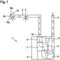
- the ASD is denoted with reference numeral 1 and comprises one or more sampling pipes 2 (may be a sampling pipe network) and a central unit 4.
- the ASD 1 may further comprise an exhaust pipe 5.
- the central unit 4 may comprise a filter 6, a sensing chamber 7 comprising a smoke detection unit 8, and an aspiration unit 9, e.g. an aspirator or fan.
- the smoke detection unit 8 may be a high sensitivity sensor and is configured to detect smoke particles suspended in air in the sensing chamber.
- the aspiration unit 9 is configured to draw air from the protected area to the sensing chamber 7.
- the filter 6 may remove all large particles that may damage the sensor within the sensing chamber.
- the exhaust pipe 5 may expel the sampled air from the ASD.
- Each sampling pipe 2 has a detection-side end 2a, a detection-remote end 2b and sampling holes 3 between the detection-side end 2a and the detection-remote end 2b.
- the sampling holes 3 allow air to be suck into the sampling pipe 2 and transported to the central unit 4 by means of the aspiration unit 9.
- the sampling pipe network is configured to collect air through the sampling holes 3 and transports it from the protected space to the central unit 4, where it is tested for the presence of smoke particulate.
- the arrows illustrate the air flow from the time it enters the sampling pipe to the point it is exhausted out of the ASD.
- the ASD 1 further comprises a differential pressure sensor arrangement 10 that is configured to determine at least one differential pressure value between a first measuring site 10a and a second measuring site 10b.
- the differential pressure sensor arrangement 10 comprises a differential pressure sensor that is configured to measure the differential pressure between inside and outside of the pipe at the detection-remote end 2b.
- the first measuring site 10a is inside the sampling pipe 2 at the detection-remote end 2b
- the second measuring site 10b is outside of the sampling pipe 2 at the detection-remote end 2b.
- the ASD further comprises a monitoring unit 11 that is configured to perform an embodiment of the inventive method, as shown in Figure 3 .
- the monitoring unit 11 is comprised in the housing of the ASD 1.
- the monitoring unit 11 can also be arranged outside the housing of the ASD 1 and may be a separate device.
- the ASD comprises a data communication device which is set up to connect the differential pressure sensor arrangement 10 to the monitoring unit 11 in a data-transmitting manner (illustrated by circle segments).
- the data communication device can comprise radio or cable transmission techniques.
- the data communication device can comprise e.g. a Wi-Fi, near field communication (NFC), Bluetooth, Zigbee, Zwave device etc.
- the data communication device can be comprised in the housing of the ASD 1 and/or in the monitoring unit 11.
- the data communication device can also be a separate device that is connected to the monitoring unit 11.
- the ASD can comprise a single pipe configuration with one pipe connected to the detector and extending through the entire covered space, as shown in Fig. 1 . Selecting this configuration may result in longer pipe runs and delay sampled air collection at the detector.
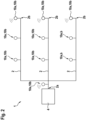
- the ASD can comprise a multiple pipe configuration, composed of multiple or branched pipes 3, as shown in Fig. 2 .
- a differential pressure measurement between inside and outside of the pipe at the detection-remote end 2b of the pipe 2 can be performed.
- a differential pressure measurement between inside and outside of the pipe at the detection-side end 2a of the pipe 2 can be performed (illustrated by dashed line circle).
- a differential pressure measurement between inside the pipe at the detection-remote end 2b and inside the pipe at the detection-side end 2a can be performed.
- the first and second measuring sites 10a, 10b can be freely distributed along the pipe 3 (illustrated by the solid and dashed line circles), wherein the respective second measuring sites 10b can be inside or outside the pipe.
- a differential pressure sensor can be used, and can be mounted in the pipe wall, as shown in Fig. 1 .
- Figure 3 shows a block diagram of an embodiment of the inventive method of monitoring of monitoring the ASD 1.
- a step 301 at least one differential pressure value is determined by means of the differential pressure sensor arrangement 10.
- the least one differential pressure value with compared with a threshold pressure value can be preset by a user.
- the user can input the threshold pressure into the monitoring device 11 by a human-machine-interface. Therefore, the threshold pressure value can be adjusted to suit the prevailing site conditions.
- a fault of the ASD 1 is detected, when and if the at least one differential pressure value exceeds the threshold pressure value, or falls below the pressure value, respectively.
- the differential pressure may increase or decrease in case of a pipe fault, as will be aware to the skilled person.
Landscapes
- Engineering & Computer Science (AREA)
- Computer Security & Cryptography (AREA)
- Physics & Mathematics (AREA)
- General Physics & Mathematics (AREA)
- Fire-Detection Mechanisms (AREA)
Abstract
Description
- The present invention relates to an aspirating smoke detector, a method and a device for monitoring an aspirating smoke detector.
- An aspirating smoke detector comprises a sampling pipe system and one or more smoke detection units. The sampling pipe system has sampling holes (aspiration openings). An aspirating unit like a fan continuously draws in air from the monitored area via the sampling pipe system. Each sampling hole can be regarded as a single smoke detector. The air samples are permanently fed to the smoke detection unit where they are analysed for smoke particles. As a rule, particularly highly sensitive optical smoke detectors are used as smoke detection units.
- It may be envisaged that the aspirating smoke detector also has a monitoring unit that triggers an alarm or error message if the volumetric air flow through the detection unit changes, e.g. by +/-20 % or more.
- However, it may happen in practice that in the event of a sampling pipe break halfway, the monitoring unit may not register a fault, but several sampling holes may be "disconnected" from the evaluation unit and fail to detect fire events. This is because there is insufficient airflow change due to the break and this cannot be detected by the airflow measurement techniques in the monitoring unit. The more sampling pipes the sampling pipe system has, the more sampling holes can be disconnected without being noticed.
-
EP 0 333 290 A1 shows a monitoring device for checking faults, such as breach or clogging of an aspiration duct with one or more sampling points of a fire detection system, which system contains a source of a reactive agent gas connected to the input end of the duct, a sensor for this agent and an electronic signal handling system receiving the output of this sensor in order to detect faults in the duct. - According to the invention, an aspirating smoke detector, a method and a device for monitoring an aspirating smoke detector with the features of the independent patent claims are proposed. Advantageous embodiments are the subject of the dependent claims and the following description.
- The invention provides a system that monitors aspirating smoke detector sampling pipes end to end and is capable of detecting an open or broken sampling pipe anywhere along the entire length of the sampling pipe easily and reliably.
- The aspirating smoke detector comprises a smoke detection unit, an aspiration unit and a sampling pipe having a detection-side end, a detection-remote end and one or more sampling holes between the detection end and the detection-remote end. The aspirating smoke detector is arranged to suck air through the sampling holes into the sampling pipe in the direction of the detection-side end by means of the aspiration unit and to supply it to the smoke detection unit.
- The aspirating smoke detector comprises a differential pressure sensor arrangement that is configured to determine at least one differential pressure value between a first measuring site and a second measuring site. The first measuring site is inside the sampling pipe, and the second measuring site is inside the sampling pipe and remotely from the first measuring site, or is outside of the sampling pipe.
- According to the invention, (at least one) differential pressure value can be used to monitor the aspiration smoke detector by measuring the differential pressure between inside and outside of the sampling pipe (i.e. second measuring site outside the sampling pipe, ambient air pressure) or by measuring the differential pressure between two sites in the sampling pipe (i.e. second measuring site inside the sampling pipe).
- Under normal circumstances the aspiration unit in the aspirating smoke detector creates a negative pressure in the sampling pipe (with respect to ambient air pressure) which is strongest (most negative) at the detection-side end. The pressure gradually approaches the ambient air pressure along the sampling pipe toward the detection-remote end. The negative pressure at the detection-remote end is still easily detectable using standard air pressure sensors commonly available. Tests have shown that differential pressures between ambient pressure and the pressure at the detection-remote end are typically in a range of around 50 - 100 Pa.
- Under a fault condition (open or broken sampling pipe) the differential air pressure between the open sampling pipe and ambient atmosphere becomes essentially zero upstream of the sampling pipe break. This applies no matter where the sampling pipe break occurs. Further to this a stalled aspiration unit or totally blocked sampling pipe is also detectable by reduced pressure difference.
- In an embodiment, the first measuring site comprises the detection-remote end of the at least one sampling pipe. In this case, the second measuring site may be outside of the sampling pipe, or may be inside the sampling pipe downstream the detection-remote end. The second measuring site may be the detection-side end of the sampling pipe. As discussed above, differential pressures between ambient pressure and the pressure at the detection-remote end are typically in a range of around 50-100 Pa and can be easily measured. Correspondingly, differential pressures between the pressure at the detection-remote end and the pressure at the detection-side end as a second measuring site inside the sampling pipe are typically in a range of around 80 - 140 Pa and can be easily measured, too. Thus, the detection-remote end is an advantageous first measuring site.
- Nevertheless, other first measuring sites are advantageous, too. In an embodiment, the first measuring site is located between the detection-remote end and the detection-side end of the sampling pipe. Then, the second measuring site may be outside of the sampling pipe, or may be inside the sampling pipe downstream the first measuring site. The first measuring site may be the detection-side end of the sampling pipe, and the second measuring site may be outside of the sampling pipe. With all these configurations, reliable differential pressure values can be measured.
- Depending on the specific arrangement of the first and the second measuring sites as discussed above, the differential pressure may increase or decrease in case of a pipe fault, as will be aware to the skilled person. Accordingly, a fault of the aspirating smoke detector may be detected either when the at least one differential pressure value exceeds the threshold pressure value, or when the at least one differential pressure value falls below the pressure value. Correspondingly, it may be determined that the aspirating smoke detector is functional if the at least one differential pressure value does not exceed the threshold pressure value, or if the at least one differential pressure does not fall below the pressure value, respectively.
- In an embodiment, the differential pressure measurement arrangement can comprise more than one first measuring sites and/or more than one second measuring sites, the more than one first measuring sites being arranged along the sampling pipe, and the or more than one second measuring sites being outside of the sampling pipe or being inside the sampling pipe and remotely from an associated first measuring site. For each pair of a first and an associated second measuring site, a differential pressure value can be determined. By this, multiple differential pressure values can be used to monitor the aspiration smoke detector.
- In an embodiment, the aspirating smoke detector or the monitoring unit comprises a data communication device which is set up to connect the differential pressure sensor arrangement to the monitoring unit in a data-transmitting manner. The data communication device can comprise radio or cable transmission techniques. The data communication device can comprise e.g. a Wi-Fi, near field communication (NFC), Bluetooth, ZigBee, Z-Wave device etc. The monitoring unit may be comprised in the aspiration smoke detector, may be a separate device, or may be a node on an addressable system such as a fire alarm loop.
- In an embodiment, the threshold pressure value can be preset by a user. The threshold pressure value (the point at which the pressure difference is set to create a fault) could be made programmable and therefore be adjusted to suit the prevailing site conditions. It is envisaged that the threshold pressure value can be set up using an "app" or application on a computing unit, including a mobile phone or (tablet) computer. The computing unit may connect to the monitoring unit by radio or cable transmission technology, especially as described above. Alternatively, the threshold value could also be configured manually (i.e. using a DIL switch, rotary switch, micro-jumpers etc.).
- In an embodiment, the at least one differential pressure value can be stored over time, e.g. in the monitoring unit or a storage connected to the monitoring unit. This corresponds to a logbook or data collecting function. The differential pressure value(s) can be stored periodically. It may be envisaged that the stored pressure values can be downloaded externally, e.g. to an app, or PC application at a later date to allow a site engineer to view changes in pressure and hence determine exactly when a sampling pipe break occurred. This data could also be used at the site survey stage, to show how the pressure varied over a period of time and therefore permit a skilled person to select and program the suitable threshold pressure values. Additionally, the data could be processed live, or post-processed by suitable machine learning algorithms to provide threshold values that are tailored to the prevailing site conditions (e.g. changes due to environmental conditions, temperature, local pressure changes etc.).
- A monitoring unit according to the invention is set up, in particular programmatically, to carry out a method according to the invention.
- The implementation of a method according to the invention in the form of a computer program or computer program product with program code for carrying out all method steps is also advantageous, since this causes particularly low costs, especially if an executing control device is still used for further tasks and is therefore present anyway. Finally, a machine-readable storage medium is provided with a computer program stored thereon as described above. Suitable storage media or data carriers for providing the computer program are in particular magnetic, optical and electrical memories, such as hard disks, flash memories, EEPROMs, DVDs and the like. It is also possible to download a programme via computer networks (internet, intranet, etc.). Such a download can be wired or wireless (e.g. via a WLAN network, a 3G, 4G, 5G or 6G connection, etc.).
- Further advantages and embodiments of the invention are apparent from the description and the accompanying drawing.
- The invention is illustrated schematically by means of an embodiment the drawing and is described below with reference to the drawing.
-
-
Figure 1 schematically shows the working principle of an aspirating smoke detector according to an embodiment of the invention. -
Figure 2 schematically shows a further embodiment of an aspirating smoke detector according to the invention. -
Figure 3 schematically shows an embodiment of a monitoring method of an aspirating smoke detector according to the invention. - Referring to
Figures 1 and2 , embodiments of an aspirating smoke detector, ASD, according to the invention are described in the following. - The ASD is denoted with reference numeral 1 and comprises one or more sampling pipes 2 (may be a sampling pipe network) and a
central unit 4. The ASD 1 may further comprise an exhaust pipe 5. - In the illustrated example, the
central unit 4 may comprise afilter 6, asensing chamber 7 comprising a smoke detection unit 8, and an aspiration unit 9, e.g. an aspirator or fan. The smoke detection unit 8 may be a high sensitivity sensor and is configured to detect smoke particles suspended in air in the sensing chamber. The aspiration unit 9 is configured to draw air from the protected area to thesensing chamber 7. Thefilter 6 may remove all large particles that may damage the sensor within the sensing chamber. The exhaust pipe 5 may expel the sampled air from the ASD. - Each
sampling pipe 2 has a detection-side end 2a, a detection-remote end 2b andsampling holes 3 between the detection-side end 2a and the detection-remote end 2b. The sampling holes 3 allow air to be suck into thesampling pipe 2 and transported to thecentral unit 4 by means of the aspiration unit 9. The sampling pipe network is configured to collect air through the sampling holes 3 and transports it from the protected space to thecentral unit 4, where it is tested for the presence of smoke particulate. The arrows illustrate the air flow from the time it enters the sampling pipe to the point it is exhausted out of the ASD. - The ASD 1 further comprises a differential
pressure sensor arrangement 10 that is configured to determine at least one differential pressure value between afirst measuring site 10a and asecond measuring site 10b. In the embodiment ofFig. 1 , the differentialpressure sensor arrangement 10 comprises a differential pressure sensor that is configured to measure the differential pressure between inside and outside of the pipe at the detection-remote end 2b. Thus, thefirst measuring site 10a is inside thesampling pipe 2 at the detection-remote end 2b, and thesecond measuring site 10b is outside of thesampling pipe 2 at the detection-remote end 2b. - The ASD further comprises a
monitoring unit 11 that is configured to perform an embodiment of the inventive method, as shown inFigure 3 . InFigure 1 , themonitoring unit 11 is comprised in the housing of the ASD 1. However, it should be pointed out that themonitoring unit 11 can also be arranged outside the housing of the ASD 1 and may be a separate device. - The ASD comprises a data communication device which is set up to connect the differential
pressure sensor arrangement 10 to themonitoring unit 11 in a data-transmitting manner (illustrated by circle segments). The data communication device can comprise radio or cable transmission techniques. The data communication device can comprise e.g. a Wi-Fi, near field communication (NFC), Bluetooth, Zigbee, Zwave device etc. The data communication device can be comprised in the housing of the ASD 1 and/or in themonitoring unit 11. The data communication device can also be a separate device that is connected to themonitoring unit 11. - The ASD can comprise a single pipe configuration with one pipe connected to the detector and extending through the entire covered space, as shown in
Fig. 1 . Selecting this configuration may result in longer pipe runs and delay sampled air collection at the detector. Alternatively, the ASD can comprise a multiple pipe configuration, composed of multiple or branchedpipes 3, as shown inFig. 2 . - In
Fig. 2 , various embodiments of the differentialpressure sensor arrangement 10 are illustrated. According to an embodiment, a differential pressure measurement between inside and outside of the pipe at the detection-remote end 2b of thepipe 2 can be performed. According to a further embodiment, a differential pressure measurement between inside and outside of the pipe at the detection-side end 2a of thepipe 2 can be performed (illustrated by dashed line circle). According to a yet further embodiment, a differential pressure measurement between inside the pipe at the detection-remote end 2b and inside the pipe at the detection-side end 2a can be performed. - Generally, the first and
second measuring sites second measuring sites 10b can be inside or outside the pipe. In case asecond measuring site 10b is outside the pipe, a differential pressure sensor can be used, and can be mounted in the pipe wall, as shown inFig. 1 . -
Figure 3 shows a block diagram of an embodiment of the inventive method of monitoring of monitoring the ASD 1. - In a
step 301, at least one differential pressure value is determined by means of the differentialpressure sensor arrangement 10. - In a
step 302, the least one differential pressure value with compared with a threshold pressure value. The threshold pressure value can be preset by a user. E.g. the user can input the threshold pressure into themonitoring device 11 by a human-machine-interface. Therefore, the threshold pressure value can be adjusted to suit the prevailing site conditions. - In a
step 303, a fault of the ASD 1 is detected, when and if the at least one differential pressure value exceeds the threshold pressure value, or falls below the pressure value, respectively. Depending on the specific arrangement of the first and thesecond measuring sites Figs. 1 and2 , the differential pressure may increase or decrease in case of a pipe fault, as will be aware to the skilled person.
Claims (13)
- An aspirating smoke detector (1) comprising a smoke detection unit (8), an aspiration unit (9) and a sampling pipe (2) having a detection-side end (2a), a detection-remote end (2b) and sampling holes (3) between the detection-side end (2a) and the detection-remote end (2b),wherein the aspirating smoke detector (1) is arranged to suck air through the sampling holes (3) into the sampling pipe (2) in the direction of the detection-side end (2a) by means of the aspiration unit (9) and to supply it to the smoke detection unit (8),comprising a differential pressure sensor arrangement (10) configured to determine at least one differential pressure value between a first measuring site (10a) and a second measuring site (10b), the first measuring site (10a) being inside the sampling pipe (2), and the second measuring site (10b) being outside of the sampling pipe (2) or being inside the sampling pipe (2) and remotely from the first measuring site (10a).
- The aspirating smoke detector (1) according to claim 1, wherein the first measuring site (10a) comprises the detection-remote end (2b) of the sampling pipe (2).
- The aspirating smoke detector (1) according to claim 1 or 2, wherein the second measuring site (10b) comprises the detection-side end (2a) of the sampling pipe (2).
- The aspirating smoke detector (1) according to claim 1, wherein the first measuring site (10a) comprises the detection-side end (2a) of the sampling pipe (2), and the second measuring site (10b) is outside of the sampling pipe (2).
- The aspirating smoke detector (1) according to any one of the preceding claims, comprising a data communication device which is set up to connect the differential pressure sensor arrangement (10) to a monitoring unit (11) in a data-transmitting manner.
- A method of monitoring an aspirating smoke detector (1), especially an aspirating smoke detector (1) according to any one of the preceding claims, comprising:determining (301) at least one differential pressure value by means of a differential pressure sensor arrangement (10) between a first measuring site (10a) and a second measuring site (10b), the first measuring site (10a) being inside a sampling pipe (2) of the aspirating smoke detector (1) and the second measuring site (10b) being outside of the sampling pipe (2) or being inside the sampling pipe (2) and remotely from the first measuring site (10a), comparing (302) the least one differential pressure value with a threshold pressure value,detecting (303) a fault of the aspirating smoke detector (1) when the at least one differential pressure value exceeds the threshold pressure value, or falls below the pressure value, respectively.
- The method according to claim 6, further comprising:
determining that the aspirating smoke detector (1) is functional if the at least one differential pressure value does not exceed the threshold pressure value, or does not fall below the pressure value, respectively. - The method according to claim 6 or 7, further comprising:
presetting the threshold pressure value by a user. - The method according to any one of claims 6 to 8, further comprising:
storing the at least one differential pressure value over time. - The monitoring unit (11) of an aspirating smoke detector (1), especially the aspirating smoke detector (1) according to any one of claims 1 to 5, being arranged to perform all the steps of a method according to any one of claims 6 to 9.
- The aspirating smoke detector (1) according to any one of claims 1 to 5, comprising the monitoring unit (11) of claim 10.
- A computer program that causes the monitoring unit (11) of claim 10 to perform all method steps of a method according to any one of claims 6 to 9 when executed on the monitoring unit (11).
- A machine-readable storage medium having a computer program stored thereon according to claim 12.
Priority Applications (1)
| Application Number | Priority Date | Filing Date | Title |
|---|---|---|---|
| EP23168648.6A EP4451244A1 (en) | 2023-04-19 | 2023-04-19 | Aspirating smoke detector, method and device for monitoring an aspirating smoke detector |
Applications Claiming Priority (1)
| Application Number | Priority Date | Filing Date | Title |
|---|---|---|---|
| EP23168648.6A EP4451244A1 (en) | 2023-04-19 | 2023-04-19 | Aspirating smoke detector, method and device for monitoring an aspirating smoke detector |
Publications (1)
| Publication Number | Publication Date |
|---|---|
| EP4451244A1 true EP4451244A1 (en) | 2024-10-23 |
Family
ID=86095796
Family Applications (1)
| Application Number | Title | Priority Date | Filing Date |
|---|---|---|---|
| EP23168648.6A Pending EP4451244A1 (en) | 2023-04-19 | 2023-04-19 | Aspirating smoke detector, method and device for monitoring an aspirating smoke detector |
Country Status (1)
| Country | Link |
|---|---|
| EP (1) | EP4451244A1 (en) |
Citations (3)
| Publication number | Priority date | Publication date | Assignee | Title |
|---|---|---|---|---|
| EP0333290A1 (en) | 1988-03-15 | 1989-09-20 | Van Rietschoten & Houwens Noord-West B.V. | Device for monitoring the suction vent duct(s) of a smoke/gas detection system |
| US20040246137A1 (en) * | 2003-05-02 | 2004-12-09 | Axel Bobenhausen | Apparatus for monitoring a smoke detector |
| US20210348982A1 (en) * | 2020-05-08 | 2021-11-11 | Carrier Corporation | Detection of leakage in an aspirating fire detection system |
-
2023
- 2023-04-19 EP EP23168648.6A patent/EP4451244A1/en active Pending
Patent Citations (3)
| Publication number | Priority date | Publication date | Assignee | Title |
|---|---|---|---|---|
| EP0333290A1 (en) | 1988-03-15 | 1989-09-20 | Van Rietschoten & Houwens Noord-West B.V. | Device for monitoring the suction vent duct(s) of a smoke/gas detection system |
| US20040246137A1 (en) * | 2003-05-02 | 2004-12-09 | Axel Bobenhausen | Apparatus for monitoring a smoke detector |
| US20210348982A1 (en) * | 2020-05-08 | 2021-11-11 | Carrier Corporation | Detection of leakage in an aspirating fire detection system |
Similar Documents
| Publication | Publication Date | Title |
|---|---|---|
| EP2244236B1 (en) | Variable air speed aspirating smoke detector | |
| US9373238B2 (en) | Multi-channel aspirated smoke detector | |
| AU2017201651B2 (en) | Fire detection | |
| EP1089239A2 (en) | Embedded engine diagnostic system | |
| US8629780B2 (en) | Method of detecting and localizing a fire based on a time difference and air speeds of monitored air in pipe conduits | |
| US11609144B2 (en) | Detection of leakage in an aspirating fire detection system | |
| EP2881922B2 (en) | Redundant input pipe networks in aspirated smoke detectors | |
| EP4216187B1 (en) | Monitoring of the integrity of an aspirating detection system | |
| EP3023953B1 (en) | System and method of airflow monitoring for variable airflow environments | |
| US11704987B2 (en) | Increasing the suction power in an aspirating smoke detector (ASD) to shorten the transport time from a detected minimum signal level value without the output of an interruption signal | |
| CN119649581A (en) | An intelligent early warning system for laboratory hazardous gas leakage | |
| EP1665189B1 (en) | Method and apparatus for determining operational condition of pollution monitoring equipment | |
| EP4451244A1 (en) | Aspirating smoke detector, method and device for monitoring an aspirating smoke detector | |
| WO2018193060A1 (en) | Pressure safety valve activation sensor | |
| KR100191643B1 (en) | Control method and its apparatus of communication hole | |
| US9459243B2 (en) | Ultrasonic transducers in aspirating smoke detectors for transport time measurement | |
| CN210039031U (en) | Comprehensive pipe rack fire disaster active detection device | |
| CN120252813A (en) | Method for predicting sensor failure in safety systems | |
| HK1213681B (en) | Fire detection |
Legal Events
| Date | Code | Title | Description |
|---|---|---|---|
| PUAI | Public reference made under article 153(3) epc to a published international application that has entered the european phase |
Free format text: ORIGINAL CODE: 0009012 |
|
| STAA | Information on the status of an ep patent application or granted ep patent |
Free format text: STATUS: THE APPLICATION HAS BEEN PUBLISHED |
|
| AK | Designated contracting states |
Kind code of ref document: A1 Designated state(s): AL AT BE BG CH CY CZ DE DK EE ES FI FR GB GR HR HU IE IS IT LI LT LU LV MC ME MK MT NL NO PL PT RO RS SE SI SK SM TR |
|
| STAA | Information on the status of an ep patent application or granted ep patent |
Free format text: STATUS: REQUEST FOR EXAMINATION WAS MADE |
|
| 17P | Request for examination filed |
Effective date: 20250423 |
|
| GRAP | Despatch of communication of intention to grant a patent |
Free format text: ORIGINAL CODE: EPIDOSNIGR1 |
|
| STAA | Information on the status of an ep patent application or granted ep patent |
Free format text: STATUS: GRANT OF PATENT IS INTENDED |