EP1089239A2 - Embedded engine diagnostic system - Google Patents
Embedded engine diagnostic system Download PDFInfo
- Publication number
- EP1089239A2 EP1089239A2 EP00306462A EP00306462A EP1089239A2 EP 1089239 A2 EP1089239 A2 EP 1089239A2 EP 00306462 A EP00306462 A EP 00306462A EP 00306462 A EP00306462 A EP 00306462A EP 1089239 A2 EP1089239 A2 EP 1089239A2
- Authority
- EP
- European Patent Office
- Prior art keywords
- fault
- mission data
- response
- data
- parameters
- Prior art date
- Legal status (The legal status is an assumption and is not a legal conclusion. Google has not performed a legal analysis and makes no representation as to the accuracy of the status listed.)
- Granted
Links
Images


Classifications
-
- G—PHYSICS
- G07—CHECKING-DEVICES
- G07C—TIME OR ATTENDANCE REGISTERS; REGISTERING OR INDICATING THE WORKING OF MACHINES; GENERATING RANDOM NUMBERS; VOTING OR LOTTERY APPARATUS; ARRANGEMENTS, SYSTEMS OR APPARATUS FOR CHECKING NOT PROVIDED FOR ELSEWHERE
- G07C3/00—Registering or indicating the condition or the working of machines or other apparatus, other than vehicles
-
- F—MECHANICAL ENGINEERING; LIGHTING; HEATING; WEAPONS; BLASTING
- F02—COMBUSTION ENGINES; HOT-GAS OR COMBUSTION-PRODUCT ENGINE PLANTS
- F02C—GAS-TURBINE PLANTS; AIR INTAKES FOR JET-PROPULSION PLANTS; CONTROLLING FUEL SUPPLY IN AIR-BREATHING JET-PROPULSION PLANTS
- F02C9/00—Controlling gas-turbine plants; Controlling fuel supply in air- breathing jet-propulsion plants
-
- F—MECHANICAL ENGINEERING; LIGHTING; HEATING; WEAPONS; BLASTING
- F05—INDEXING SCHEMES RELATING TO ENGINES OR PUMPS IN VARIOUS SUBCLASSES OF CLASSES F01-F04
- F05D—INDEXING SCHEME FOR ASPECTS RELATING TO NON-POSITIVE-DISPLACEMENT MACHINES OR ENGINES, GAS-TURBINES OR JET-PROPULSION PLANTS
- F05D2260/00—Function
- F05D2260/80—Diagnostics
Abstract
Description
- The invention relates generally to engine diagnostic systems and in particular to an engine diagnostic system which is embedded in the aircraft and does not require external systems to detect a fault. The U.S. Air Force currently downloads mission data from each F-16 at the end of each day. The data is transferred to portable data transfer devices and subsequently downloaded into ground support systems. This data is then compared to previous mission data and performance faults are determined based on trend data. The support equipment infrastructure has been unreliable and expensive to maintain.
- This system requires significant maintenance manpower resources and exposes the engine and aircraft to the potential of undetected trend faults due to ground system equipment related problems. In addition, the existing system would not enunciate a trend fault until the end of the day which could be after multiple missions. In a deployed scenario, the support equipment must be transported to the remote site to determine if a performance fault exists.
- An exemplary embodiment of the invention is an engine diagnostic system including a plurality of sensors. One of the plurality of sensors includes a speed sensor generating a speed value indicative of aircraft speed. A processor is coupled to the sensors and stores current mission data in a data memory when the speed value is within a predetermined velocity range. A fault indicator is provided which is visible from the exterior of the aircraft. The processor detects a presence or absence of a fault in response to the current mission data and activates the fault indicator in response to the presence of a fault.
- Another exemplary embodiment of the invention is a method for detecting faults in an aircraft. The method includes determining when aircraft speed is within a predetermined velocity range and obtaining current mission data in response to the aircraft speed being within the velocity range. The presence or absence of a fault is detected in response to the current mission data. A fault indicator is activated in response to the presence of the fault.
- Embodiments of the invention will now be described, by way of example, with reference to the accompanying drawings, in which:-
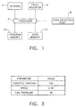
- FIG. 1 is a block diagram of an embedded engine diagnostic system in an exemplary embodiment of the invention;
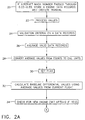
- FIGS. 2A and 2B depict a flowchart of the processing performed by the embedded engine diagnostic system in an exemplary embodiment of the invention;
- FIG. 3 depicts an exemplary data record; and
- FIG. 4 is a plot of baseline differential value versus mission number for an engine parameter.
-
- FIG.1 is a block diagram of an embedded engine diagnostic system in an exemplary embodiment of the invention. The embedded engine diagnostic system includes a
processor 2 which executes the diagnostic process described herein with reference to FIGS. 2A and 2B.Processor 2 may be implemented using existing microprocessors.Sensors 4 are coupled to theprocessor 2 and provide values for engine parameters (such as fuel rate) and/or aircraft parameters (such as Mach number) to theprocessor 2. Aprogram memory 10 is a non-volatile memory which contains the program to be executed by theprocessor 2. Theprogram memory 10 may be electrically programmable (such as an EEPROM) so that the program to be executed byprocessor 2 can be updated. Adata memory 12 stores current mission data and prior mission data for a plurality of prior missions which are used to detect faults as described herein. Thedata memory 12 may be implemented using known non-volatile memory. Acommunications port 8 is coupled toprocessor 2 and is used to upload configuration data (e.g., aircraft type, engine type, etc.) or download configuration data and mission data fromdata memory 12. Thecommunications port 8 may use existing communications protocols such as RS232. Thecommunications port 8 is preferably accessible from the exterior of the aircraft. - Upon detection of a fault, the processor activates a
fault indicator 6. Thefault indicator 6 may include an indicator visible by the pilot (e.g., an LED in the cockpit) and an indicator visible from the exterior of the aircraft (e.g., an LED or mechanical device at the wheel well strut). Providing a direct indication of a fault on the exterior of the aircraft eliminates the need to download mission data to ground systems to detect a fault and provides fault detection for each mission. - FIGS. 2A and 2B depict a flowchart of the processing performed by the embedded engine diagnostic system in an exemplary embodiment of the invention. In the embodiment shown in FIGS. 2A and 2B, the embedded engine diagnostic system is programmed to detect faults during take-off. It is understood that other processes may be performed by the embedded engine diagnostic system. The process begins at
step 20 where the aircraft speed is monitored to detect when the aircraft is within a velocity range. An exemplary velocity range is about Mach 0.22 to about Mach 0.33. In this speed range, the aircraft is in the take-off process and the engine is in a stable state and up to normal operating temperature. When the aircraft is within this velocity range, the embedded engine diagnostic system sequentially acquires a plurality of data records (e.g., four). Acquiring data under uniform conditions (e.g., within a predetermined velocity range) results in more accurate detection of faults. The multiple data records are separated by a sampling interval (e.g., ½ second). Each of the data records contains values indicative of parameters including engine parameters or aircraft parameters. An exemplary data record is shown in FIG. 3 which depicts the parameters sensed bysensors 4 and the values for each parameter. - Once the multiple data records are acquired, the process may pause for a period of time (e.g., three minutes) prior to proceeding to
step 22. The embedded engine diagnostic system will generate a fault indication in the cockpit throughfault indicator 6. Activation of the fault indicator may be delayed until the aircraft completes takeoff. - At
step 22, the value processing routine is initiated to preprocess the sensor data acquired atstep 20 prior to detection of faults. Atstep 24, a validation routine is performed on the values in each of the data records. The validation routine may apply various tests to determine if the sampled data is appropriate for detecting faults. The goal is to confirm that the values in each data record are suitable for detecting faults. Because the embedded engine diagnostic system compares current mission data to prior mission data to generate faults, the current mission data is validated to ensure an accurate comparison. An exemplary validation is confirming that a value for a parameter has remained constant over the multiple samplings. For example, for accurate comparison to past missions, it may be necessary that the throttle position remain constant for all data records. Another exemplary validation is confirming that values for a parameter are within a predetermined range. If the values in the data records fail validation, the process is ended. - Once the values in each data record are validated, a single average data record is generated at
step 26. The average data record which contains an average value, derived from the multiple data records, for each parameter. At 28, the average values are converted into the appropriate engineering units if necessary. Thesensors 4 may generate signals in terms of abstract units (e.g., voltage, counts per second, etc.). Atstep 28, these abstract units are converted to engineering units (e.g., pressure, speed, etc.) due to the fact that the fault detection in an exemplary embodiment of the invention is performed based on engineering units. - Once
step 28 is completed, a flag is set atstep 30 to indicate that the acquired values are suitable for processing to detect faults. At 32, baseline differential values are determined for each parameter in the average data record. A baseline differential value indicates the difference between an average value from a sensor and a predicted new engine, baseline value (e.g., predicted from a model or other source). The baseline differential value can be represented in a variety of ways including a difference (i.e., Xsensed ― Xpredicted) or a ratio (i.e., Xsensed / Xpredicted). - At
step 34, it is determined whether the engine is new. Designating an engine as new sets a mission history counter kpts to zero indicating that no prior mission data stored in memory is to be used in detecting faults. An engine may be classified as new upon a variety of conditions including initial installation, maintenance, retrofit, etc. Prior mission data is saved as the new engine completes missions. Until prior mission data is available, the embedded engine diagnostic system detects a limited number of faults that do not require prior mission data for detection. - At
step 36, the kpts counter is incremented and prior mission data is incremented to create space for the current mission data. In effect, the prior mission data is stored in a first-in, first-out manner in which mission data beyond the thirty past missions is removed from memory. Once the memory is shifted instep 36, the current mission data (i.e., average values and baseline differential values) is stored instep 38. - Once the prior mission data has been updated to remove mission data beyond thirty prior missions and the current mission data has been stored, the embedded engine diagnostic system initiates a fault detection process as shown at
step 40. Astep 42, all available prior mission data (i.e., prior average values and prior baseline differential values for each parameter) is retrieved. Atstep 44, the current average values and current baseline differential values for each parameter are retrieved. This prior mission data and current mission data are processed to detect faults instep 46. A variety of faults can be detected by the embedded engine diagnostic system in response to current mission data and prior mission data. For example, a leak in a compressor line is detected if the compressor bleed pressure drops by more than 25 psi for two consecutive missions. Flow path deterioration is detected if the turbine exit temperature (T4B) increases faster than a predetermined rate. It is understood that a variety of faults may be detected and the invention is not limited to the examples disclosed herein. - FIG. 4 depicts the detection of faults based on baseline differential values. FIG. 4 depicts baseline differential values (shown as a difference between the average value and the predicted new engine, baseline value) versus mission number for turbine exit temperature (DT4B). As shown in FIG. 4, the baseline differential value DT4B varies over missions. One technique used for detecting a fault is computing the slope of the baseline differential value plot. A large slope may indicate a fault. Another technique used for detecting a fault is computing the slopes of both the T4B and corrected operating point (PHI) baseline differential value plots. A large slope on both indicates a higher probability of a real fault. Other known fault criteria may be applied to detect faults such as an average value exceeding a threshold. Other known techniques may be used to detect faults based on the mission data. Existing techniques to reduce the occurrence of false fault indications may also be used.
- Referring to FIG. 2, once fault detection is performed at
step 46, fault data indicative of the absence or presence of a fault is stored in thedata memory 12. An exemplary technique for recording the occurrence of a fault is to store a one or zero in a memory location corresponding to a fault. If a one is stored in the memory location, this indicates that the corresponding fault was detected. Atstep 50, the stored fault data is examined to determine the existence of a fault.Step 50 may perform a logical OR operation on the values in the fault memory locations so that any one fault will result in activating thefault indicator 6. If a fault is detected, thefault indicator 6 is activated atstep 52, otherwise the routine exits atstep 54. As noted above, thefault indicator 6 may include a visual indicator in the cockpit for the pilot (e.g., an LED) and a visual indicator which is visible from the outside of the aircraft (e.g., an LED or mechanical device). The specific cause of the fault can be detected directly next to the aircraft by using a data transfer and display device (e.g., a portable computer). - The embedded engine diagnostic system eliminates the need to download data from each aircraft each day. The embedded engine diagnostic system also provides continuous monitoring of faults throughout each mission and is not degraded by ground system equipment failures.
- As described above, the present invention can be embodied in the form of computer-implemented processes and apparatuses for practicing those processes. The present invention can also be embodied in the form of computer program code containing instructions embodied in tangible media, such as floppy diskettes, CD ROMs, hard drives, or any other computer-readable storage medium, wherein, when the computer program code is loaded into and executed by a computer, the computer becomes an apparatus for practicing the invention. The present invention can also be embodied in the form of computer program code, for example, whether stored in a storage medium, loaded into and/or executed by a computer, or transmitted over some transmission medium, such as over electrical wiring or cabling, through fiber optics, or via electromagnetic radiation, wherein, when the computer program code is loaded into and executed by a computer, the computer becomes an apparatus for practicing the invention. When implemented on a general-purpose microprocessor, the computer program code segments configure the microprocessor to create specific logic circuits.
- For completeness, various aspects of the invention are set out in the following numbered clauses:-
- 1. An engine diagnostic system comprising:
- a plurality of sensors (4), one of said plurality of sensors including a speed sensor generating a speed value indicative of aircraft speed;
- a data memory (12);
- a processor (2) coupled to said sensors, said processor storing current mission data in said data memory when said speed value is within a predetermined velocity range; and,
- a fault indicator (6) visible from the exterior of the aircraft;
said processor detecting a presence or absence of a fault in response to said current mission data and activating said fault indicator in response to said presence of a fault. - 2. The engine diagnostic system of
clause 1 wherein: - said current mission data includes values for parameters and baseline differential values for said parameters.
- 3. The engine diagnostic system of
clause 2 wherein: - said parameters include aircraft parameters and engine parameters.
- 4. The engine diagnostic system of
clause 2 wherein: - said values include average values.
- 5. The engine diagnostic system of
clause 1 wherein: - said data memory includes prior mission data; and
- said processor detects the presence or absence of a fault in response to said current mission data and said prior mission data.
- 6. The engine diagnostic system of
clause 2 wherein: - said processor validates said values prior to detecting the presence or absence of a fault.
- 7. The engine diagnostic system of
clause 1 wherein: - said fault indicator includes a visual indicator visible to a pilot.
- 8. The engine diagnostic system of
clause 1 wherein: - said velocity range is about Mach 0.22 to about Mach 0.33.
- 9. A method for detecting faults in an aircraft comprising:
- determining (20) when aircraft speed is within a predetermined velocity range; obtaining (20) current mission data in response to the aircraft speed being within said velocity range;
- detecting (40) a presence or absence of a fault in response to current mission data; and
- activating (52) a fault indicator in response to said presence of a fault.
- 10. The method of
clause 9 wherein: - said current mission data includes values for parameters and baseline differential values for said parameters.
- 11. The method of
clause 10 wherein: - said parameters include aircraft parameters and engine parameters.
- 12. The method of
clause 10 wherein: - said values include average values.
- 13. The method of
clause 9 further comprising: - storing prior mission data; wherein said detecting the presence or absence of a fault is in response to said current mission data and said prior mission data.
- 14. The method of
clause 10 further comprising: - validating (24) said values prior to detecting the presence or absence of a fault.
- 15. The method of
clause 9 wherein: - said fault indicator is visible from the exterior of the aircraft
- 16. The method of
clause 9 wherein: - said fault indicator includes a visual indicator visible to a pilot.
- 17. The method of
clause 9 wherein: - said velocity range is about Mach 0.22 to about Mach 0.33.
- 18. A storage medium encoded with machine-readable computer program code for
detecting faults in an aircraft, the storage medium including instructions for causing a
computer to implement:
- determining (20) when aircraft speed is within a predetermined velocity range;
- obtaining (20) a plurality of values indicative of parameters in response to the aircraft speed being within said velocity range;
- detecting (40) a presence or absence of a fault in response to said plurality of values; and
- activating (52) a fault indicator in response to said presence of a fault.
- 19. The storage medium of
clause 18 wherein: - said current mission data includes values for parameters and baseline differential values for said parameters.
- 20. The storage medium of
clause 19 wherein: - said parameters include aircraft parameters and engine parameters.
- 21. The storage medium of
clause 19 wherein: - said values include average values.
- 22. The storage medium of
clause 18 further comprising program code for causing the computer to implement: - storing prior mission data;
wherein said detecting a presence or absence of a fault is in response to said current mission data and said prior mission data. - 23. The storage medium of
clause 19 further comprising program code for causing the computer to implement: - validating (24) said values prior to detecting a presence or absence of a fault.
- 24. The storage medium of
clause 18 wherein: - said velocity range is about Mach 0.22 to about Mach 0.33.
-
Claims (10)
- An engine diagnostic system comprising:a plurality of sensors (4), one of said plurality of sensors including a speed sensor generating a speed value indicative of aircraft speed;a data memory (12);a processor (2) coupled to said sensors, said processor storing current mission data in said data memory when said speed value is within a predetermined velocity range; and,a fault indicator (6) visible from the exterior of the aircraft;
said processor detecting a presence or absence of a fault in response to said current mission data and activating said fault indicator in response to said presence of a fault. - The engine diagnostic system of claim 1 wherein:said current mission data includes values for parameters and baseline differential values for said parameters.
- The engine diagnostic system of claim 2 wherein:said parameters include aircraft parameters and engine parameters, and said values include average values.
- The engine diagnostic system of claim 1 wherein:said data memory includes prior mission data; andsaid processor detects the presence or absence of a fault in response to said current mission data and said prior mission data.
- A method for detecting faults in an aircraft comprising:determining (20) when aircraft speed is within a predetermined velocity range; obtaining (20) current mission data in response to the aircraft speed being within said velocity range;detecting (40) a presence or absence of a fault in response to current mission data; andactivating (52) a fault indicator in response to said presence of a fault.
- The method of claim 5 wherein:said current mission data includes values for parameters and baseline differential values for said parameters.
- The method of claim 5 further comprising:storing prior mission data; wherein said detecting the presence or absence of a fault is in response to said current mission data and said prior mission data.
- A storage medium encoded with machine-readable computer program code for detecting faults in an aircraft, the storage medium including instructions for causing a computer to implement:determining (20) when aircraft speed is within a predetermined velocity range;obtaining (20) a plurality of values indicative of parameters in response to the aircraft speed being within said velocity range;detecting (40) a presence or absence of a fault in response to said plurality of values; andactivating (52) a fault indicator in response to said presence of a fault.
- The storage medium of claim 8 wherein:said current mission data includes values for parameters and baseline differential values for said parameters.
- The storage medium of claim 8 further comprising program code for causing the computer to implement:storing prior mission data;
wherein said detecting a presence or absence of a fault is in response to said current mission data and said prior mission data.
Applications Claiming Priority (2)
| Application Number | Priority Date | Filing Date | Title |
|---|---|---|---|
| US410238 | 1982-08-23 | ||
| US09/410,238 US6292723B1 (en) | 1999-09-30 | 1999-09-30 | Embedded engine diagnostic system |
Publications (3)
| Publication Number | Publication Date |
|---|---|
| EP1089239A2 true EP1089239A2 (en) | 2001-04-04 |
| EP1089239A3 EP1089239A3 (en) | 2004-06-16 |
| EP1089239B1 EP1089239B1 (en) | 2009-10-07 |
Family
ID=23623860
Family Applications (1)
| Application Number | Title | Priority Date | Filing Date |
|---|---|---|---|
| EP00306462A Expired - Lifetime EP1089239B1 (en) | 1999-09-30 | 2000-07-28 | Embedded engine diagnostic system |
Country Status (7)
| Country | Link |
|---|---|
| US (1) | US6292723B1 (en) |
| EP (1) | EP1089239B1 (en) |
| JP (1) | JP4482206B2 (en) |
| AT (1) | ATE445206T1 (en) |
| DE (1) | DE60043089D1 (en) |
| ES (1) | ES2331944T3 (en) |
| IL (1) | IL137521A (en) |
Cited By (1)
| Publication number | Priority date | Publication date | Assignee | Title |
|---|---|---|---|---|
| US8260093B2 (en) | 2007-11-14 | 2012-09-04 | Rolls-Royce, Plc | Component monitoring arrangement |
Families Citing this family (33)
| Publication number | Priority date | Publication date | Assignee | Title |
|---|---|---|---|---|
| SG97893A1 (en) * | 2000-06-29 | 2003-08-20 | Singapore Tech Aerospace Ltd | A method of monitoring and displaying health performance of an aircraft engine |
| JP2003182473A (en) * | 2001-12-18 | 2003-07-03 | Fuji Heavy Ind Ltd | Self diagnosing apparatus of display device for vehicle |
| US7415243B2 (en) | 2003-03-27 | 2008-08-19 | Honda Giken Kogyo Kabushiki Kaisha | System, method and computer program product for receiving data from a satellite radio network |
| US7818380B2 (en) | 2003-12-15 | 2010-10-19 | Honda Motor Co., Ltd. | Method and system for broadcasting safety messages to a vehicle |
| US8041779B2 (en) | 2003-12-15 | 2011-10-18 | Honda Motor Co., Ltd. | Method and system for facilitating the exchange of information between a vehicle and a remote location |
| EP1733513A4 (en) | 2004-04-06 | 2009-05-06 | Honda Motor Co Ltd | Method and system for controlling the exchange of vehicle related messages |
| US7518530B2 (en) | 2004-07-19 | 2009-04-14 | Honda Motor Co., Ltd. | Method and system for broadcasting audio and visual display messages to a vehicle |
| US7643788B2 (en) | 2004-09-22 | 2010-01-05 | Honda Motor Co., Ltd. | Method and system for broadcasting data messages to a vehicle |
| US7280941B2 (en) * | 2004-12-29 | 2007-10-09 | General Electric Company | Method and apparatus for in-situ detection and isolation of aircraft engine faults |
| US7562049B2 (en) | 2005-03-29 | 2009-07-14 | Honda Motor Co., Ltd. | Payment system and method for data broadcasted from a remote location to vehicles |
| US7949330B2 (en) | 2005-08-25 | 2011-05-24 | Honda Motor Co., Ltd. | System and method for providing weather warnings and alerts |
| US7677452B2 (en) * | 2006-06-30 | 2010-03-16 | Caterpillar Inc. | Method and system for providing signatures for machines |
| US7690565B2 (en) * | 2006-06-30 | 2010-04-06 | Caterpillar Inc. | Method and system for inspecting machines |
| US7819312B2 (en) * | 2006-06-30 | 2010-10-26 | Caterpillar Inc | Method and system for operating machines |
| US8565998B2 (en) * | 2006-11-27 | 2013-10-22 | United Technologies Corporation | Gas turbine engine having on-engine data storage device |
| US7668653B2 (en) | 2007-05-31 | 2010-02-23 | Honda Motor Co., Ltd. | System and method for selectively filtering and providing event program information |
| US8099308B2 (en) | 2007-10-02 | 2012-01-17 | Honda Motor Co., Ltd. | Method and system for vehicle service appointments based on diagnostic trouble codes |
| US8131509B2 (en) * | 2008-03-23 | 2012-03-06 | United Technologies Corporation | Method of system design for failure detectability |
| US20090326754A1 (en) * | 2008-06-30 | 2009-12-31 | Honeywell International Inc. | Systems and methods for engine diagnosis using wavelet transformations |
| FR2946023B1 (en) * | 2009-06-02 | 2014-11-28 | Airbus France | METHOD AND DEVICE FOR TROUBLESHOOTING |
| US8135804B2 (en) | 2009-07-07 | 2012-03-13 | Honda Motor Co., Ltd. | Method for scheduling and rescheduling vehicle service appointments |
| US8862433B2 (en) | 2010-05-18 | 2014-10-14 | United Technologies Corporation | Partitioning of turbomachine faults |
| US8494889B2 (en) | 2011-06-14 | 2013-07-23 | International Business Machines Corporation | Optimized maintenance schedules based on smart city maintenance profiles |
| CN102320382A (en) * | 2011-07-07 | 2012-01-18 | 中国国际航空股份有限公司 | Aircraft performance detection method |
| GB2513132B (en) * | 2013-04-16 | 2015-05-27 | Ge Aviat Systems Ltd | Method for predicting a bleed air system fault |
| GB2513133B (en) | 2013-04-16 | 2015-07-08 | Ge Aviat Systems Ltd | Methods for predicting a speed brake system fault |
| FR3009396B1 (en) | 2013-07-31 | 2017-03-17 | Airbus Operations Sas | METHOD AND COMPUTER PROGRAM FOR AIDING THE MAINTENANCE OF AIRCRAFT EQUIPMENT |
| FR3011105B1 (en) * | 2013-09-20 | 2017-01-27 | Airbus Operations Sas | METHOD FOR IDENTIFYING FAILURE EQUIPMENT IN AN AIRCRAFT |
| JP6164573B2 (en) * | 2015-05-19 | 2017-07-19 | 株式会社アドテックス | Unmanned flying vehicle and control system therefor |
| AT517689B1 (en) | 2015-11-11 | 2017-04-15 | Avl List Gmbh | Method of creating a test |
| US10592749B2 (en) | 2016-11-14 | 2020-03-17 | General Electric Company | Systems and methods for analyzing turns at an airport |
| US10834336B2 (en) | 2018-01-29 | 2020-11-10 | Ge Aviation Systems Llc | Thermal imaging of aircraft |
| US11107307B2 (en) * | 2018-05-01 | 2021-08-31 | Ford Global Technologies, Llc | Systems and methods for probabilistic on-board diagnostics |
Citations (2)
| Publication number | Priority date | Publication date | Assignee | Title |
|---|---|---|---|---|
| US3731070A (en) | 1971-04-27 | 1973-05-01 | United Aircraft Corp | Gas turbine engine analyzer |
| US5050081A (en) | 1988-11-14 | 1991-09-17 | The United States Of America As Represented By The Administrator Of The National Aeronautics And Space Administration | Method and system for monitoring and displaying engine performance parameters |
Family Cites Families (8)
| Publication number | Priority date | Publication date | Assignee | Title |
|---|---|---|---|---|
| US4215412A (en) * | 1978-07-13 | 1980-07-29 | The Boeing Company | Real time performance monitoring of gas turbine engines |
| GB2128569B (en) * | 1982-10-22 | 1985-12-24 | British Aerospace | Aircraft maintenance data terminal |
| US4587614A (en) * | 1982-12-28 | 1986-05-06 | United Technologies Corporation | System fault detection in electrostatic flow diagnostics |
| US4625280A (en) * | 1982-12-28 | 1986-11-25 | United Technologies Corporation | Sectional distress isolating electrostatic engine diagnostics |
| US5070458A (en) * | 1989-03-31 | 1991-12-03 | Honeywell Inc. | Method of analyzing and predicting both airplane and engine performance characteristics |
| US5018069A (en) | 1989-07-13 | 1991-05-21 | Howell Instruments, Inc. | Reference system and method for diagnosing aircraft engine conditions |
| US5408412A (en) | 1992-04-09 | 1995-04-18 | United Technologies Corporation | Engine fault diagnostic system |
| US5951611A (en) | 1996-11-18 | 1999-09-14 | General Electric Company | Diagnostic trend analysis |
-
1999
- 1999-09-30 US US09/410,238 patent/US6292723B1/en not_active Expired - Lifetime
-
2000
- 2000-07-26 IL IL13752100A patent/IL137521A/en not_active IP Right Cessation
- 2000-07-28 EP EP00306462A patent/EP1089239B1/en not_active Expired - Lifetime
- 2000-07-28 DE DE60043089T patent/DE60043089D1/en not_active Expired - Lifetime
- 2000-07-28 ES ES00306462T patent/ES2331944T3/en not_active Expired - Lifetime
- 2000-07-28 JP JP2000228021A patent/JP4482206B2/en not_active Expired - Fee Related
- 2000-07-28 AT AT00306462T patent/ATE445206T1/en not_active IP Right Cessation
Patent Citations (2)
| Publication number | Priority date | Publication date | Assignee | Title |
|---|---|---|---|---|
| US3731070A (en) | 1971-04-27 | 1973-05-01 | United Aircraft Corp | Gas turbine engine analyzer |
| US5050081A (en) | 1988-11-14 | 1991-09-17 | The United States Of America As Represented By The Administrator Of The National Aeronautics And Space Administration | Method and system for monitoring and displaying engine performance parameters |
Cited By (1)
| Publication number | Priority date | Publication date | Assignee | Title |
|---|---|---|---|---|
| US8260093B2 (en) | 2007-11-14 | 2012-09-04 | Rolls-Royce, Plc | Component monitoring arrangement |
Also Published As
| Publication number | Publication date |
|---|---|
| EP1089239B1 (en) | 2009-10-07 |
| IL137521A0 (en) | 2001-07-24 |
| ES2331944T3 (en) | 2010-01-21 |
| EP1089239A3 (en) | 2004-06-16 |
| JP4482206B2 (en) | 2010-06-16 |
| DE60043089D1 (en) | 2009-11-19 |
| ATE445206T1 (en) | 2009-10-15 |
| US6292723B1 (en) | 2001-09-18 |
| JP2001206295A (en) | 2001-07-31 |
| IL137521A (en) | 2004-07-25 |
Similar Documents
| Publication | Publication Date | Title |
|---|---|---|
| EP1089239B1 (en) | Embedded engine diagnostic system | |
| US8528317B2 (en) | Method and system for detecting the ingestion of an object by an aircraft turbine engine during a mission | |
| US8744651B2 (en) | Method of determining a maneuver performed by an aircraft | |
| US7197430B2 (en) | Method and apparatus for determining engine part life usage | |
| US7369932B2 (en) | System and method for turbine engine fault detection using discrete event system modeling | |
| US10359339B2 (en) | Monitoring system for an engine test bench | |
| EP3401749B1 (en) | Fault detection using high resolution realms | |
| US20090014245A1 (en) | Systems and Methods for Monitoring Gas Turbine Engines | |
| US20040176879A1 (en) | Transient fault detection system and method using Hidden Markov Models | |
| US8869603B2 (en) | Debris detection in turbomachinery and gas turbine engines | |
| WO2006111679A2 (en) | Method and device for monitoring an aircraft structure | |
| Fisher | Gas path debris monitoring-a 21/sup st/century PHM tool | |
| JP2015024810A (en) | System and method for monitoring aircraft wing anti-icing valve | |
| US11472568B2 (en) | Prognostic monitoring of complementary air data system sensors | |
| US7369965B2 (en) | System and method for turbine engine anomaly detection | |
| US10551818B2 (en) | Fault detection methods and systems | |
| US7249287B2 (en) | Methods and apparatus for providing alarm notification | |
| US4218879A (en) | Overspeed protection device | |
| US20220390328A1 (en) | Method for monitoring the torsion of a rotary shaft on a turbomachine of an aircraft | |
| EP3296513B1 (en) | Propeller health monitoring | |
| RU2817575C1 (en) | Method of controlling thermal state of electronic controller of gas turbine engine | |
| EP3683642B1 (en) | Method for measuring fatigue for mechanical components of an aircraft | |
| Budrow | System analysis and integration of diagnostics and health management for the F-119-PW-100 | |
| Broadwater et al. | Time stress measurement device use for on-board diagnostic support | |
| Banjac et al. | Enhanced Monitoring Capabilities for Legacy Engine Programs |
Legal Events
| Date | Code | Title | Description |
|---|---|---|---|
| PUAI | Public reference made under article 153(3) epc to a published international application that has entered the european phase |
Free format text: ORIGINAL CODE: 0009012 |
|
| AK | Designated contracting states |
Kind code of ref document: A2 Designated state(s): AT BE CH CY DE DK ES FI FR GB GR IE IT LI LU MC NL PT SE |
|
| AX | Request for extension of the european patent |
Free format text: AL;LT;LV;MK;RO;SI |
|
| PUAL | Search report despatched |
Free format text: ORIGINAL CODE: 0009013 |
|
| AK | Designated contracting states |
Kind code of ref document: A3 Designated state(s): AT BE CH CY DE DK ES FI FR GB GR IE IT LI LU MC NL PT SE |
|
| AX | Request for extension of the european patent |
Extension state: AL LT LV MK RO SI |
|
| RIC1 | Information provided on ipc code assigned before grant |
Ipc: 7B 64D 45/00 B Ipc: 7G 07C 3/00 A |
|
| 17P | Request for examination filed |
Effective date: 20041216 |
|
| AKX | Designation fees paid |
Designated state(s): AT BE CH CY DE DK ES FI FR GB GR IE IT LI LU MC NL PT SE |
|
| APBN | Date of receipt of notice of appeal recorded |
Free format text: ORIGINAL CODE: EPIDOSNNOA2E |
|
| APBR | Date of receipt of statement of grounds of appeal recorded |
Free format text: ORIGINAL CODE: EPIDOSNNOA3E |
|
| APBV | Interlocutory revision of appeal recorded |
Free format text: ORIGINAL CODE: EPIDOSNIRAPE |
|
| GRAP | Despatch of communication of intention to grant a patent |
Free format text: ORIGINAL CODE: EPIDOSNIGR1 |
|
| GRAS | Grant fee paid |
Free format text: ORIGINAL CODE: EPIDOSNIGR3 |
|
| GRAA | (expected) grant |
Free format text: ORIGINAL CODE: 0009210 |
|
| AK | Designated contracting states |
Kind code of ref document: B1 Designated state(s): AT BE CH CY DE DK ES FI FR GB GR IE IT LI LU MC NL PT SE |
|
| REG | Reference to a national code |
Ref country code: GB Ref legal event code: FG4D |
|
| REG | Reference to a national code |
Ref country code: CH Ref legal event code: EP |
|
| REG | Reference to a national code |
Ref country code: IE Ref legal event code: FG4D |
|
| REF | Corresponds to: |
Ref document number: 60043089 Country of ref document: DE Date of ref document: 20091119 Kind code of ref document: P |
|
| REG | Reference to a national code |
Ref country code: ES Ref legal event code: FG2A Ref document number: 2331944 Country of ref document: ES Kind code of ref document: T3 |
|
| NLV1 | Nl: lapsed or annulled due to failure to fulfill the requirements of art. 29p and 29m of the patents act | ||
| PG25 | Lapsed in a contracting state [announced via postgrant information from national office to epo] |
Ref country code: PT Free format text: LAPSE BECAUSE OF FAILURE TO SUBMIT A TRANSLATION OF THE DESCRIPTION OR TO PAY THE FEE WITHIN THE PRESCRIBED TIME-LIMIT Effective date: 20100208 Ref country code: FI Free format text: LAPSE BECAUSE OF FAILURE TO SUBMIT A TRANSLATION OF THE DESCRIPTION OR TO PAY THE FEE WITHIN THE PRESCRIBED TIME-LIMIT Effective date: 20091007 Ref country code: SE Free format text: LAPSE BECAUSE OF FAILURE TO SUBMIT A TRANSLATION OF THE DESCRIPTION OR TO PAY THE FEE WITHIN THE PRESCRIBED TIME-LIMIT Effective date: 20091007 |
|
| PG25 | Lapsed in a contracting state [announced via postgrant information from national office to epo] |
Ref country code: BE Free format text: LAPSE BECAUSE OF FAILURE TO SUBMIT A TRANSLATION OF THE DESCRIPTION OR TO PAY THE FEE WITHIN THE PRESCRIBED TIME-LIMIT Effective date: 20091007 Ref country code: AT Free format text: LAPSE BECAUSE OF FAILURE TO SUBMIT A TRANSLATION OF THE DESCRIPTION OR TO PAY THE FEE WITHIN THE PRESCRIBED TIME-LIMIT Effective date: 20091007 |
|
| PG25 | Lapsed in a contracting state [announced via postgrant information from national office to epo] |
Ref country code: NL Free format text: LAPSE BECAUSE OF FAILURE TO SUBMIT A TRANSLATION OF THE DESCRIPTION OR TO PAY THE FEE WITHIN THE PRESCRIBED TIME-LIMIT Effective date: 20091007 Ref country code: DK Free format text: LAPSE BECAUSE OF FAILURE TO SUBMIT A TRANSLATION OF THE DESCRIPTION OR TO PAY THE FEE WITHIN THE PRESCRIBED TIME-LIMIT Effective date: 20091007 |
|
| PLBE | No opposition filed within time limit |
Free format text: ORIGINAL CODE: 0009261 |
|
| STAA | Information on the status of an ep patent application or granted ep patent |
Free format text: STATUS: NO OPPOSITION FILED WITHIN TIME LIMIT |
|
| 26N | No opposition filed |
Effective date: 20100708 |
|
| PG25 | Lapsed in a contracting state [announced via postgrant information from national office to epo] |
Ref country code: GR Free format text: LAPSE BECAUSE OF FAILURE TO SUBMIT A TRANSLATION OF THE DESCRIPTION OR TO PAY THE FEE WITHIN THE PRESCRIBED TIME-LIMIT Effective date: 20100108 |
|
| PG25 | Lapsed in a contracting state [announced via postgrant information from national office to epo] |
Ref country code: MC Free format text: LAPSE BECAUSE OF NON-PAYMENT OF DUE FEES Effective date: 20100731 |
|
| REG | Reference to a national code |
Ref country code: CH Ref legal event code: PL |
|
| PG25 | Lapsed in a contracting state [announced via postgrant information from national office to epo] |
Ref country code: CH Free format text: LAPSE BECAUSE OF NON-PAYMENT OF DUE FEES Effective date: 20100731 Ref country code: LI Free format text: LAPSE BECAUSE OF NON-PAYMENT OF DUE FEES Effective date: 20100731 |
|
| PG25 | Lapsed in a contracting state [announced via postgrant information from national office to epo] |
Ref country code: IE Free format text: LAPSE BECAUSE OF NON-PAYMENT OF DUE FEES Effective date: 20100728 |
|
| PG25 | Lapsed in a contracting state [announced via postgrant information from national office to epo] |
Ref country code: CY Free format text: LAPSE BECAUSE OF FAILURE TO SUBMIT A TRANSLATION OF THE DESCRIPTION OR TO PAY THE FEE WITHIN THE PRESCRIBED TIME-LIMIT Effective date: 20091007 |
|
| PG25 | Lapsed in a contracting state [announced via postgrant information from national office to epo] |
Ref country code: LU Free format text: LAPSE BECAUSE OF NON-PAYMENT OF DUE FEES Effective date: 20100728 |
|
| REG | Reference to a national code |
Ref country code: FR Ref legal event code: PLFP Year of fee payment: 17 |
|
| PGFP | Annual fee paid to national office [announced via postgrant information from national office to epo] |
Ref country code: IT Payment date: 20160722 Year of fee payment: 17 Ref country code: GB Payment date: 20160727 Year of fee payment: 17 Ref country code: DE Payment date: 20160726 Year of fee payment: 17 |
|
| PGFP | Annual fee paid to national office [announced via postgrant information from national office to epo] |
Ref country code: FR Payment date: 20160726 Year of fee payment: 17 |
|
| PGFP | Annual fee paid to national office [announced via postgrant information from national office to epo] |
Ref country code: ES Payment date: 20160726 Year of fee payment: 17 |
|
| REG | Reference to a national code |
Ref country code: DE Ref legal event code: R119 Ref document number: 60043089 Country of ref document: DE |
|
| GBPC | Gb: european patent ceased through non-payment of renewal fee |
Effective date: 20170728 |
|
| REG | Reference to a national code |
Ref country code: FR Ref legal event code: ST Effective date: 20180330 |
|
| PG25 | Lapsed in a contracting state [announced via postgrant information from national office to epo] |
Ref country code: GB Free format text: LAPSE BECAUSE OF NON-PAYMENT OF DUE FEES Effective date: 20170728 Ref country code: DE Free format text: LAPSE BECAUSE OF NON-PAYMENT OF DUE FEES Effective date: 20180201 |
|
| PG25 | Lapsed in a contracting state [announced via postgrant information from national office to epo] |
Ref country code: FR Free format text: LAPSE BECAUSE OF NON-PAYMENT OF DUE FEES Effective date: 20170731 |
|
| PG25 | Lapsed in a contracting state [announced via postgrant information from national office to epo] |
Ref country code: IT Free format text: LAPSE BECAUSE OF NON-PAYMENT OF DUE FEES Effective date: 20170728 |
|
| REG | Reference to a national code |
Ref country code: ES Ref legal event code: FD2A Effective date: 20181029 |
|
| PG25 | Lapsed in a contracting state [announced via postgrant information from national office to epo] |
Ref country code: ES Free format text: LAPSE BECAUSE OF NON-PAYMENT OF DUE FEES Effective date: 20170729 |