EP0333290A1 - Device for monitoring the suction vent duct(s) of a smoke/gas detection system - Google Patents
Device for monitoring the suction vent duct(s) of a smoke/gas detection system Download PDFInfo
- Publication number
- EP0333290A1 EP0333290A1 EP89200644A EP89200644A EP0333290A1 EP 0333290 A1 EP0333290 A1 EP 0333290A1 EP 89200644 A EP89200644 A EP 89200644A EP 89200644 A EP89200644 A EP 89200644A EP 0333290 A1 EP0333290 A1 EP 0333290A1
- Authority
- EP
- European Patent Office
- Prior art keywords
- signal
- reactive agent
- gas
- amplifier
- duct
- Prior art date
- Legal status (The legal status is an assumption and is not a legal conclusion. Google has not performed a legal analysis and makes no representation as to the accuracy of the status listed.)
- Granted
Links
- 238000001514 detection method Methods 0.000 title claims abstract description 25
- 239000000779 smoke Substances 0.000 title claims description 19
- 238000012544 monitoring process Methods 0.000 title claims description 12
- 238000012806 monitoring device Methods 0.000 claims abstract description 6
- QGZKDVFQNNGYKY-UHFFFAOYSA-N Ammonia Chemical group N QGZKDVFQNNGYKY-UHFFFAOYSA-N 0.000 claims description 20
- 239000004065 semiconductor Substances 0.000 claims description 12
- 238000010438 heat treatment Methods 0.000 claims description 8
- 238000005070 sampling Methods 0.000 abstract description 3
- 239000007789 gas Substances 0.000 description 42
- 239000003795 chemical substances by application Substances 0.000 description 30
- 229910021529 ammonia Inorganic materials 0.000 description 6
- XOLBLPGZBRYERU-UHFFFAOYSA-N tin dioxide Chemical compound O=[Sn]=O XOLBLPGZBRYERU-UHFFFAOYSA-N 0.000 description 4
- 230000008859 change Effects 0.000 description 3
- 238000006243 chemical reaction Methods 0.000 description 3
- 239000004800 polyvinyl chloride Substances 0.000 description 3
- NLXLAEXVIDQMFP-UHFFFAOYSA-N Ammonia chloride Chemical compound [NH4+].[Cl-] NLXLAEXVIDQMFP-UHFFFAOYSA-N 0.000 description 2
- 238000010521 absorption reaction Methods 0.000 description 2
- 238000011161 development Methods 0.000 description 2
- 230000000694 effects Effects 0.000 description 2
- 238000005259 measurement Methods 0.000 description 2
- 229910000069 nitrogen hydride Inorganic materials 0.000 description 2
- 229920000915 polyvinyl chloride Polymers 0.000 description 2
- OKTJSMMVPCPJKN-UHFFFAOYSA-N Carbon Chemical compound [C] OKTJSMMVPCPJKN-UHFFFAOYSA-N 0.000 description 1
- VEXZGXHMUGYJMC-UHFFFAOYSA-N Hydrochloric acid Chemical compound Cl VEXZGXHMUGYJMC-UHFFFAOYSA-N 0.000 description 1
- 230000009471 action Effects 0.000 description 1
- 235000019270 ammonium chloride Nutrition 0.000 description 1
- 230000003321 amplification Effects 0.000 description 1
- 230000008901 benefit Effects 0.000 description 1
- 229910052799 carbon Inorganic materials 0.000 description 1
- 230000003197 catalytic effect Effects 0.000 description 1
- 239000000919 ceramic Substances 0.000 description 1
- 239000004020 conductor Substances 0.000 description 1
- 230000007547 defect Effects 0.000 description 1
- 230000001419 dependent effect Effects 0.000 description 1
- 238000009413 insulation Methods 0.000 description 1
- 239000012212 insulator Substances 0.000 description 1
- 239000000463 material Substances 0.000 description 1
- 238000000034 method Methods 0.000 description 1
- 239000003595 mist Substances 0.000 description 1
- 238000003199 nucleic acid amplification method Methods 0.000 description 1
- 230000003287 optical effect Effects 0.000 description 1
- 238000013021 overheating Methods 0.000 description 1
- 238000007254 oxidation reaction Methods 0.000 description 1
- 239000012495 reaction gas Substances 0.000 description 1
- 230000009257 reactivity Effects 0.000 description 1
- 230000035945 sensitivity Effects 0.000 description 1
Images
Classifications
-
- G—PHYSICS
- G01—MEASURING; TESTING
- G01M—TESTING STATIC OR DYNAMIC BALANCE OF MACHINES OR STRUCTURES; TESTING OF STRUCTURES OR APPARATUS, NOT OTHERWISE PROVIDED FOR
- G01M3/00—Investigating fluid-tightness of structures
- G01M3/02—Investigating fluid-tightness of structures by using fluid or vacuum
- G01M3/04—Investigating fluid-tightness of structures by using fluid or vacuum by detecting the presence of fluid at the leakage point
- G01M3/20—Investigating fluid-tightness of structures by using fluid or vacuum by detecting the presence of fluid at the leakage point using special tracer materials, e.g. dye, fluorescent material, radioactive material
- G01M3/22—Investigating fluid-tightness of structures by using fluid or vacuum by detecting the presence of fluid at the leakage point using special tracer materials, e.g. dye, fluorescent material, radioactive material for pipes, cables or tubes; for pipe joints or seals; for valves; for welds; for containers, e.g. radiators
-
- G—PHYSICS
- G08—SIGNALLING
- G08B—SIGNALLING OR CALLING SYSTEMS; ORDER TELEGRAPHS; ALARM SYSTEMS
- G08B17/00—Fire alarms; Alarms responsive to explosion
- G08B17/10—Actuation by presence of smoke or gases, e.g. automatic alarm devices for analysing flowing fluid materials by the use of optical means
- G08B17/117—Actuation by presence of smoke or gases, e.g. automatic alarm devices for analysing flowing fluid materials by the use of optical means by using a detection device for specific gases, e.g. combustion products, produced by the fire
Definitions
- the invention relates to a device for monitoring the suction vent duct(s) of a smoke/gas detection system.
- a plurality of measuring points are monitored by means of a suction vent duct which, in these measuring points, sucks air toward a measuring detector connected at the beginning of the suction duct, which detector in case of a starting fire in the vicinity of one of the measuring points detects smoke or another developing gas, for instance carbon dioxyde and issues a signal which is handled by a suitable electronic circuit to an alarm signal.
- Smoke/gas detection systems exist in which detection occurs by means of a reaction gas. From the Dutch patent application 81 04604 for instance a fire detection system is known, in which at the end of the suction duct system a source of ammonia is connected so that during the suction of a suction duct always ammonia passes through the suction duct.
- the device is especially intended for the detection of development of HCl, which is formed with a starting fire of the polyvinyl chloride insulation of electric cables. In case such a development occurs, the detector detects the presence of the ammonia chloride formed with the reaction.
- Known methods for monitoring suction ducts consists in measuring the quantity or through put through the duct and the related pressure.
- Pressure can be measured with pressure sensors, equipped with switches or transmitters.
- a disadvantage of pressure measuring is that with often very long suction ducts, which show a small pressure drop only, most pressure sensors are not sufficiently sensitive to measure pressure variations in case a duct breach occurs in the middle or at the end of the duct. If applicable one has to do with a cost problem because a highly sensitive sensor and the electronic circuit necessary for it will increase costs considerably for the concerned smoke/gas detection system.
- flow rate meters For monitoring the suction duct by means of measuring the through-put wherewith the flow varies in case of duct breach or clogging, one may use flow rate meters, thermic quantity meters and acoustical quantity meters.
- Thermic quantity meters are based on the principle that a temperature sensitive element is influenced by the air/gas quantity flowing along it.
- a temperature element can for instance be a PT-element, a thermo couple, a thermistor, or a transistor.
- a device is known for monitoring the velocity of a gas flow in a duct wherewith use is made of suchlike temperature elements.
- a drawback is here, that the element needs to be very sensitive and consequently relatively expensive, especially with long ducts.
- the acoustical quantity meters work according to the travelling time principle of sound vibrations over the length of the duct, but have the disadvantage that a very complex and expensive circuit is necessary.
- the device according the invention for that reason is characterized by -a reaction agent (gas or vapour) source, connected to the end of the suction duct(s), -a reaction agent sensitive sensor, connected to the beginning of the suction duct(s), which in dependence on the measured concentration of the reactive agent issues an electrical signal, and -a signal handling circuit, connected to the sensor, and a first comparator, which compares the output of an amplifier with an alarm reference signal and,with exceeding of a predetermined threshold,issues an alarm signal.
- a reaction agent gas or vapour
- the reactive agent gas, connected to the end of the suction duct is permamently sucked through the duct and the concentration at the beginning of the duct is measured by the sensor and transduced to an electrical signal.
- concentration measurements are relatively sensitive, in this way an accurate detection may occur over the total length of a suction duct. In case of duct breach the concentration will show a significant decrease, whereas in case of clogging of the duct no reactive agent will pass through, so that this easily can be detected.
- concentration measuring sensor a relatively simple signal handling circuit can be used, the activity of which is based on comparation of the incoming signals with standard signals for normal conditions. If an alarm signal is issued this may serve as well the purpose of switching in of a separate alarm circuit as for causing alarm lamps to light.
- the realisation may be such that the signal handling circuit contains a compensation circuit which compares the output of the amplifier with a reference signal, which is based on normal suction conditions for air and reactive agent and in dependence on this comparison issues a compensation signal to the control input of the amplifier.
- a compensation circuit which compares the output of the amplifier with a reference signal, which is based on normal suction conditions for air and reactive agent and in dependence on this comparison issues a compensation signal to the control input of the amplifier.
- the compensation signal is switched off when the amplifier output exceeds a predetermined threshold. This is desired for preventing that in case of a partly disturbance of the duct which, however, is sufficiently serious to be remedied, the amplifier will not adjust the signal to normal.
- the reactor agent store c.q. the reactive agent source, connected to the end of the suction duct, will be exhausted and issue too little reactive agent for a good measurement.
- the signal handling circuit contains a second comparator which compares the output of the amplifier with a reactive agent reference signal and with exceeding of a predetermined threshold issues an alarm signal for too low reactive agent concentration. If the compensation circuit cannot further sufficiently compensate for a reactive agent concentration which becomes too low, this will be determined by the reference in the second comparator, after which the issued alarm signal switches in an alarm circuit c.q. an alarm light.
- a gas sensitive semi-conductor element provided with a heating element, connected to a heating control.
- Suchlike semi-conductor elements are known, for instance a n-type semi-conductor, consisting of SnO2, which when heated is capable to detect gases by an increase of the electrical conductivity by gas absorption at the sensor surface.
- Suchlike semi-conductor elements react very sensitively.
- the signal handling circuit effectively may have further a temperature compensation circuit connected to the amplifier for compensating temperature variations of the semi-conductor element. In this way it is prevented that an unexpected temperature variation could cause an alarm.
- ammonia gas As reactive agent gas several possibilities exist. With the invention preferably use is made of ammonia gas as reactive agent. This gas can easily be detected in several ways due to its reactivity and moreover is relatively cheap. Another advantage of ammonia gas is that it is also used with certain smoke/gas detection system as reactive agent gas for detecting of a gas developed with a fire start. In the earlier mentioned Dutch patent application 81 04604 ammonia gas is used to detect developing HCl-vapour, which arises with heating of PVC-cover. Especially effective to suchlike smoke/gas detection can be combined with a monitoring device according to the invention, wherewith for monitoring the suction duct use is made of the same reactive agent which also is used for the smoke/gas detection.
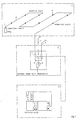
- Fig. 1 a known smoke/detection system has been shown. This consists in a suction system 1, a blower case 2, and a control unit 3.
- the suction system contains a suction duct 4, which contains a plurality of sampling points 5.
- a source of reactive agent 6 At the end of the suction duct 5 a source of reactive agent 6 has been connected which contains the reactive agent ammonia.
- detectors 7 are present at the beginning of the respective suction ducts 4 with there beyond a manifold 8 to which a blower 9 is connected, which is common for the suction ducts.
- the detectors 7 are connected to the control unit 3, which contains a signal handling circuit (not shown) and a indicator and control panel.
- PVC polyvinyl chloride
- the suction ducts which may have a duct length of 15-20 meter or more, with a diameter of 20-25 mm, are monitored for defects such as duct breach or clogging.
- defects such as duct breach or clogging.
- the downflow sampling points are completely put out of action, whereas further there will be sucked in too less NH3-reactive agent. For this reason an effective monitoring of the suction duct is necessary.
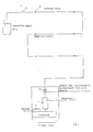
- FIG. 2 the suction system of Fig. 1 has schematically been shown wherewith, however, in the blower case 2 at the beginning of the suction duct 4 moreover a NH3-gas sensitive sensor 10 has been connected, which issues an electrical signal which is dependent on the NH3-gas concentration in the duct. In case of duct breach or clogging of the duct this concentration will change abruptly and the change of the electrical signal will be determined and evaluated by a signal handling circuit in which the inputted sensor signals are compared to reference signals and possible alarm signals are issued in dependence on this comparison.
- the invention uses a present force of reactive agent which also is used already for the smoke/gas detection system itself and which now also serves the purpose as an auxiliary means for monitoring the suction duct with respect to breach, clogging, and so on.
- the used sensor is of a n-type semi-conductor which mainly consists of SnO2, when heated capable to detect a gas concentration by increase of the electrical conductivity by absorption of this gas. In view of a sufficient sensitivity it is therewith necessary that the semi-conductor is heated.
- a suchlike sensor is known and consists of a ceramic tube, covered with a semi-conductor material and inwardly provided with a heating coil.
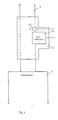
- this gas sensor 10 has been shown in Fig. 3. As is visible the gas sensor 10 has been located in a T-shaped member 11, which short above the detector 7 is connected to the beginning of the suction duct 4. Near the gas sensor 10 a temperature element 12 has been mounted to determine variations in the temperature and possible compensate them.
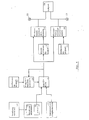
- Fig. 4 a block scheme has been shown of the signal handling circuit to which the gas sensor is connected.
- a heating element of the gas sensor 10 has been indicated, which is controlled by a heating control 14.
- the output of the sensor is connected to an amplifier 15 to which also an output of the temperature element 12 has been connected. This output is a compensation output and serves the purpose to compensate possible temperature variations in the measuring range.
- a compensation circuit 16 has been connected to the control input of the amplifier 15.
- This compensation circuit compares the output of the amplifier with a reference signal from a reference signal source 17,which reference signal is based on normal conditions of suction and reactive agent in the suction duct. In dependence on the comparison of these two signals the amplifier 15 is adjusted so that in case of no disturbance always the same output signal is obtained.
- the sensor 10 has been switched such that with decrease of the NH3-concentration in the suction duct a higher output signal is issued. If by an abrupt decrease in concentration of the NH3 this signal becomes so high, that the amplifier output exceeds a predetermined threshold value, the compensation circuit is switched off and this high amplifier signal remains.
- the output of the amplifier 15 is connected to a first comparator 19 which forms the actual disturbance circuit for duct breach, duct clogging, and so on. Also connected to this comparator 19 is an alarm reference signal source 18 which issues an alarm reference signal, which partly is derived from the output signal of amplifier 15. In the first comparator 19 the alarm reference signal and the amplifier sensor signal are compared to each other and with exceeding of a predetermined threshold the first comparator 19 gives as output an alarm signal for duct disturbancy which at the one hand fires an alarm light 22 and on the other hand is fed to an output 24, connected to a control panel.
- the output of the amplifier is also fed to a second comparator 20, which forms a disturbance circuit for the reactive agent.
- a reference signal source 21 has been connected which issues a reference signal based on "normal reactive agent". Thanks to the comparison in this second comparator at all times can be ascertained whether the reactive agent source functions sufficiently; if this is not true the second comparator issues an alarm signal at its output, which on the one hand causes an alarm light 23 to be fired and at the other hand is fed toward the output 24 to the control panel.
- the concentrations of the reactive agent gas can be ascertained.
- Other possibilities are for instance the capability of NH3 to absorb microwaves, the use of a pH-meter, measuring of the change in the conductivity of a gas stream, application of gas sensors, which work on base of catalytic oxydation, use of optical sensors wherewith colour changes are measured and such like.
- the indicated semi-conductor sensor is preferred however.
Landscapes
- Physics & Mathematics (AREA)
- General Physics & Mathematics (AREA)
- Chemical & Material Sciences (AREA)
- Analytical Chemistry (AREA)
- Business, Economics & Management (AREA)
- Emergency Management (AREA)
- Investigating Or Analyzing Materials By The Use Of Fluid Adsorption Or Reactions (AREA)
- Fire-Detection Mechanisms (AREA)
- Sampling And Sample Adjustment (AREA)
- Investigating Or Analysing Materials By Optical Means (AREA)
Abstract
Description
- The invention relates to a device for monitoring the suction vent duct(s) of a smoke/gas detection system.
- With usual smoke/gas detection systems a plurality of measuring points are monitored by means of a suction vent duct which, in these measuring points, sucks air toward a measuring detector connected at the beginning of the suction duct, which detector in case of a starting fire in the vicinity of one of the measuring points detects smoke or another developing gas, for instance carbon dioxyde and issues a signal which is handled by a suitable electronic circuit to an alarm signal. Smoke/gas detection systems exist in which detection occurs by means of a reaction gas. From the Dutch patent application 81 04604 for instance a fire detection system is known, in which at the end of the suction duct system a source of ammonia is connected so that during the suction of a suction duct always ammonia passes through the suction duct. The device is especially intended for the detection of development of HCl, which is formed with a starting fire of the polyvinyl chloride insulation of electric cables. In case such a development occurs, the detector detects the presence of the ammonia chloride formed with the reaction.
- With all such systems it is essential that the suction functions correctly. Therefore it is important that rupture or clogging of the duct is determined and repaired as soon as possible.
- Known methods for monitoring suction ducts consists in measuring the quantity or through put through the duct and the related pressure.
- Pressure can be measured with pressure sensors, equipped with switches or transmitters. A disadvantage of pressure measuring is that with often very long suction ducts, which show a small pressure drop only, most pressure sensors are not sufficiently sensitive to measure pressure variations in case a duct breach occurs in the middle or at the end of the duct. If applicable one has to do with a cost problem because a highly sensitive sensor and the electronic circuit necessary for it will increase costs considerably for the concerned smoke/gas detection system.
- For monitoring the suction duct by means of measuring the through-put wherewith the flow varies in case of duct breach or clogging, one may use flow rate meters, thermic quantity meters and acoustical quantity meters.
- The objection to flow rate meters, especially flow rate meters with floats is, that they cause a remaining pressure loss which is disturbing for the detection system, especially with long ducts.
- Thermic quantity meters are based on the principle that a temperature sensitive element is influenced by the air/gas quantity flowing along it. Such a temperature element can for instance be a PT-element, a thermo couple, a thermistor, or a transistor. From the
French patent specification 2 551 215 a device is known for monitoring the velocity of a gas flow in a duct wherewith use is made of suchlike temperature elements. A drawback is here, that the element needs to be very sensitive and consequently relatively expensive, especially with long ducts. - The acoustical quantity meters work according to the travelling time principle of sound vibrations over the length of the duct, but have the disadvantage that a very complex and expensive circuit is necessary.
- Now it is an object of the invention to provide a device for monitoring the suction duct(s) of a smoke/gas detection system, which functions effectively and reliably regardless the length of the duct to be monitored and therewith is relatively cheap to realize or apply and consequently does not form a strongly costs engraving factor for the system to be monitored.
- The device according the invention for that reason is characterized by
-a reaction agent (gas or vapour) source, connected to the end of the suction duct(s),
-a reaction agent sensitive sensor, connected to the beginning of the suction duct(s), which in dependence on the measured concentration of the reactive agent issues an electrical signal, and
-a signal handling circuit, connected to the sensor, and a first comparator, which compares the output of an amplifier with an alarm reference signal and,with exceeding of a predetermined threshold,issues an alarm signal. - According the invention the reactive agent gas, connected to the end of the suction duct is permamently sucked through the duct and the concentration at the beginning of the duct is measured by the sensor and transduced to an electrical signal. Because concentration measurements are relatively sensitive, in this way an accurate detection may occur over the total length of a suction duct. In case of duct breach the concentration will show a significant decrease, whereas in case of clogging of the duct no reactive agent will pass through, so that this easily can be detected. With such a concentration measuring sensor a relatively simple signal handling circuit can be used, the activity of which is based on comparation of the incoming signals with standard signals for normal conditions. If an alarm signal is issued this may serve as well the purpose of switching in of a separate alarm circuit as for causing alarm lamps to light.
- Effectively the realisation may be such that the signal handling circuit contains a compensation circuit which compares the output of the amplifier with a reference signal, which is based on normal suction conditions for air and reactive agent and in dependence on this comparison issues a compensation signal to the control input of the amplifier. By always adjusting the amplification on hand of the reference, one attains that fluctuations in the duct system, which per se do not mean a serious disturbance, easily can be compensated. Therewith it is preferred that the compensation signal is switched off when the amplifier output exceeds a predetermined threshold. This is desired for preventing that in case of a partly disturbance of the duct which, however, is sufficiently serious to be remedied, the amplifier will not adjust the signal to normal.
- With long activity of the monitoring device finally the reactor agent store, c.q. the reactive agent source, connected to the end of the suction duct, will be exhausted and issue too little reactive agent for a good measurement. According to invention it is possible also here to provide a monitoring with relatively simple means. Herefore the invention provides that the signal handling circuit contains a second comparator which compares the output of the amplifier with a reactive agent reference signal and with exceeding of a predetermined threshold issues an alarm signal for too low reactive agent concentration. If the compensation circuit cannot further sufficiently compensate for a reactive agent concentration which becomes too low, this will be determined by the reference in the second comparator, after which the issued alarm signal switches in an alarm circuit c.q. an alarm light.
- Though diverse possibilities exist for concentration determining gas sensors according the invention, preferably use is made of a gas sensitive semi-conductor element, provided with a heating element, connected to a heating control. Suchlike semi-conductor elements are known, for instance a n-type semi-conductor, consisting of SnO₂, which when heated is capable to detect gases by an increase of the electrical conductivity by gas absorption at the sensor surface. Suchlike semi-conductor elements react very sensitively.
- With such an embodiment the signal handling circuit effectively may have further a temperature compensation circuit connected to the amplifier for compensating temperature variations of the semi-conductor element. In this way it is prevented that an unexpected temperature variation could cause an alarm.
- As reactive agent gas several possibilities exist. With the invention preferably use is made of ammonia gas as reactive agent. This gas can easily be detected in several ways due to its reactivity and moreover is relatively cheap. Another advantage of ammonia gas is that it is also used with certain smoke/gas detection system as reactive agent gas for detecting of a gas developed with a fire start. In the earlier mentioned Dutch patent application 81 04604 ammonia gas is used to detect developing HCl-vapour, which arises with heating of PVC-cover. Especially effective to suchlike smoke/gas detection can be combined with a monitoring device according to the invention, wherewith for monitoring the suction duct use is made of the same reactive agent which also is used for the smoke/gas detection.
- The invention will further be elucidated on hand of an embodiment with reference to the drawing. In the drawing shows:
- Fig. 1 a principal scheme of a known smoke/gas detection system,
- Fig. 2 the same system, schematically indicated and provided with a monitoring device according the invention,
- Fig. 3 in greater detail the mounting of the gas sensor, and
- Fig. 4 a block scheme of the signal handling circuit which is used therewith.
- In Fig. 1 a known smoke/detection system has been shown. This consists in a
suction system 1, ablower case 2, and acontrol unit 3. - The suction system contains a
suction duct 4, which contains a plurality ofsampling points 5. At the end of the suction duct 5 a source ofreactive agent 6 has been connected which contains the reactive agent ammonia. A number ofsuchlike suction systems 1, of which only one has been shown,are connected to theblower case 2. In theblower case detectors 7 are present at the beginning of therespective suction ducts 4 with there beyond a manifold 8 to which ablower 9 is connected, which is common for the suction ducts. Thedetectors 7 are connected to thecontrol unit 3, which contains a signal handling circuit (not shown) and a indicator and control panel. - The system described in the above is especially intended for detecting a fire start with polyvinyl chloride (PVC) insulators of electrical conductors and suchlike. As is known PVC issues HCl-vapours with overheating or start of a fire, which via
sample points 5 are sucked into thesuction duct 4 and react with the present ammonia forming a NH₄Cl mist, which is detected by thedetectors 7. - In order to have such a system functioning reliably it is necessary that the suction ducts which may have a duct length of 15-20 meter or more, with a diameter of 20-25 mm, are monitored for defects such as duct breach or clogging. In case of a duct breach the downflow sampling points are completely put out of action, whereas further there will be sucked in too less NH₃-reactive agent. For this reason an effective monitoring of the suction duct is necessary.
- In Fig. 2 the suction system of Fig. 1 has schematically been shown wherewith, however, in the
blower case 2 at the beginning of thesuction duct 4 moreover a NH₃-gassensitive sensor 10 has been connected, which issues an electrical signal which is dependent on the NH₃-gas concentration in the duct. In case of duct breach or clogging of the duct this concentration will change abruptly and the change of the electrical signal will be determined and evaluated by a signal handling circuit in which the inputted sensor signals are compared to reference signals and possible alarm signals are issued in dependence on this comparison. - Effectively the invention uses a present force of reactive agent which also is used already for the smoke/gas detection system itself and which now also serves the purpose as an auxiliary means for monitoring the suction duct with respect to breach, clogging, and so on.
- The used sensor is of a n-type semi-conductor which mainly consists of SnO₂, when heated capable to detect a gas concentration by increase of the electrical conductivity by absorption of this gas. In view of a sufficient sensitivity it is therewith necessary that the semi-conductor is heated. A suchlike sensor is known and consists of a ceramic tube, covered with a semi-conductor material and inwardly provided with a heating coil.
- The actual mounting of this
gas sensor 10 has been shown in Fig. 3. As is visible thegas sensor 10 has been located in a T-shapedmember 11, which short above thedetector 7 is connected to the beginning of thesuction duct 4. Near the gas sensor 10 atemperature element 12 has been mounted to determine variations in the temperature and possible compensate them. - In Fig. 4 a block scheme has been shown of the signal handling circuit to which the gas sensor is connected. In Fig. 4 with 13 a heating element of the
gas sensor 10 has been indicated, which is controlled by aheating control 14. The output of the sensor is connected to anamplifier 15 to which also an output of thetemperature element 12 has been connected. This output is a compensation output and serves the purpose to compensate possible temperature variations in the measuring range. - Because the concentration of the reactive agent can vary due to variations in the conditions of the sucked in air or the condition of the reactive agent, a compensation circuit 16 has been connected to the control input of the
amplifier 15. This compensation circuit compares the output of the amplifier with a reference signal from a reference signal source 17,which reference signal is based on normal conditions of suction and reactive agent in the suction duct. In dependence on the comparison of these two signals theamplifier 15 is adjusted so that in case of no disturbance always the same output signal is obtained. In the considered case thesensor 10 has been switched such that with decrease of the NH₃-concentration in the suction duct a higher output signal is issued. If by an abrupt decrease in concentration of the NH₃ this signal becomes so high, that the amplifier output exceeds a predetermined threshold value, the compensation circuit is switched off and this high amplifier signal remains. - The output of the
amplifier 15 is connected to a first comparator 19 which forms the actual disturbance circuit for duct breach, duct clogging, and so on. Also connected to this comparator 19 is an alarmreference signal source 18 which issues an alarm reference signal, which partly is derived from the output signal ofamplifier 15. In the first comparator 19 the alarm reference signal and the amplifier sensor signal are compared to each other and with exceeding of a predetermined threshold the first comparator 19 gives as output an alarm signal for duct disturbancy which at the one hand fires analarm light 22 and on the other hand is fed to anoutput 24, connected to a control panel. - On the other hand the output of the amplifier is also fed to a
second comparator 20, which forms a disturbance circuit for the reactive agent. To this second comparator 20 areference signal source 21 has been connected which issues a reference signal based on "normal reactive agent". Thanks to the comparison in this second comparator at all times can be ascertained whether the reactive agent source functions sufficiently; if this is not true the second comparator issues an alarm signal at its output, which on the one hand causes an alarm light 23 to be fired and at the other hand is fed toward theoutput 24 to the control panel. - In the above the invention was elucidated on hand of an embodiment, in which in an effective way a smoke/gas detection system, working with ammonia, is combined with a monitoring device according the invention. It will be clear that the invention is not restricted to this special embodiment. On the one hand the invention is not bound to the specific ammonia detection devices for smoke/gas detection, but also other reactive agent sources can be applied. Moreover the invention can be used with suction systems in which smoke/gas detection does not occur by means of a reactive agent gas in which case the reactive agent source exclusively serves the purpose of the duct monitoring.
- Though at this moment it is preferred to use as gas sensor the above described gas sensitive semi-conductor element, it will be clear that also in other ways the concentrations of the reactive agent gas can be ascertained. Other possibilities are for instance the capability of NH₃ to absorb microwaves, the use of a pH-meter, measuring of the change in the conductivity of a gas stream, application of gas sensors, which work on base of catalytic oxydation, use of optical sensors wherewith colour changes are measured and such like. For the most economic and practically the easiest to be realized embodiments the indicated semi-conductor sensor is preferred however.
Claims (8)
characterized by
a reactive agent (gas or vapour) source connected to the end of the suction duct(s), a reactive agent sensitive sensor connected to the beginning of the suction duct(s), which issues an electrical signal in dependence on the measured reactive agent concentration, and
a signal handling circuit, connected to the sensor and provided with an amplifier, which amplifies the signal of the sensor and a first comparator which compares the output of the amplifier with an alarm reference signal and,with exceeding of a predetermined threshold,issues an alarm signal.
characterized in
that the signal handling circuit contains a compensation circuit which compares the output of the amplifier with a reference signal, which is based on normal suction conditions for air and reactive agents and in dependence on this comparison issues a compensation signal to the control input of the amplifier.
characterized in
that the compensation signal is switched off when the amplifier output exceeds a predetermined threshold.
characterized in
that the signal handling circuit contains a second comparator, which compares the output of the amplifier with a reactive agent reference signal and with exceeding of a predetermined threshold issues an alarm signal for a too low reactive agent concentration.
characterized in
that the reactive agent sensitive sensor is a gas sensitive semi-conductor element, provided with a heating element, connected to a heating control.
characterized in
that the signal handling device contains a temperature compensation circuit, connected to the amplifier to compensate temperature variations of the semi-conductor element.
characterized in
that the reactive agent is ammonia gas.
characterized in
that this system is combined with a monitoring device according to claims 1-7, in which for the suction duct use is made of the reactive agent, which is also used for the smoke/gas detection.
Applications Claiming Priority (2)
| Application Number | Priority Date | Filing Date | Title |
|---|---|---|---|
| NL8800634A NL8800634A (en) | 1988-03-15 | 1988-03-15 | DEVICE FOR MONITORING THE EXHAUST PIPE (S) OF A SMOKE / GAS DETECTION SYSTEM. |
| NL8800634 | 1988-03-15 |
Publications (2)
| Publication Number | Publication Date |
|---|---|
| EP0333290A1 true EP0333290A1 (en) | 1989-09-20 |
| EP0333290B1 EP0333290B1 (en) | 1992-11-25 |
Family
ID=19851937
Family Applications (1)
| Application Number | Title | Priority Date | Filing Date |
|---|---|---|---|
| EP19890200644 Expired - Lifetime EP0333290B1 (en) | 1988-03-15 | 1989-03-15 | Device for monitoring the suction vent duct(s) of a smoke/gas detection system |
Country Status (4)
| Country | Link |
|---|---|
| EP (1) | EP0333290B1 (en) |
| AT (1) | ATE82814T1 (en) |
| DE (1) | DE68903584D1 (en) |
| NL (1) | NL8800634A (en) |
Cited By (5)
| Publication number | Priority date | Publication date | Assignee | Title |
|---|---|---|---|---|
| EP0459944A1 (en) * | 1990-05-25 | 1991-12-04 | Incom Brandschutz Ag | Apparatus and method for object-bound fire protection of electric and/or electronic systems and utilisation of this apparatus |
| WO1996007166A1 (en) * | 1994-09-01 | 1996-03-07 | Scheefer Gerard | Device for detecting a fire in a closed-off enclosure |
| WO2000068909A1 (en) * | 1999-05-08 | 2000-11-16 | Airsense Technology Ltd. | Method and apparatus |
| US8434343B2 (en) | 2008-03-18 | 2013-05-07 | No Climb Products Limited | Testing of aspirating systems |
| EP4451244A1 (en) | 2023-04-19 | 2024-10-23 | Robert Bosch GmbH | Aspirating smoke detector, method and device for monitoring an aspirating smoke detector |
Citations (4)
| Publication number | Priority date | Publication date | Assignee | Title |
|---|---|---|---|---|
| FR2276577A1 (en) * | 1974-06-28 | 1976-01-23 | Cerberus Ag | Detection of leaks or blockages in sampling tubes - utilises parallel tube with anemometer in interconnecting tube |
| DE2755743A1 (en) * | 1977-12-14 | 1979-06-21 | Preussag Ag Feuerschutz | Early detection of operating disturbances in industrial system - using device to monitor ambient air of system continuously for foreign gases |
| NL8104604A (en) * | 1981-10-08 | 1983-05-02 | Westinghouse Electrotechniek E | SELECTIVE GAS / SMOKE DETECTION SYSTEM. |
| FR2551215A1 (en) * | 1983-08-30 | 1985-03-01 | Securiton Ag | Gas flow speed monitor for smoke detector |
-
1988
- 1988-03-15 NL NL8800634A patent/NL8800634A/en not_active Application Discontinuation
-
1989
- 1989-03-15 DE DE8989200644T patent/DE68903584D1/en not_active Expired - Lifetime
- 1989-03-15 AT AT89200644T patent/ATE82814T1/en not_active IP Right Cessation
- 1989-03-15 EP EP19890200644 patent/EP0333290B1/en not_active Expired - Lifetime
Patent Citations (4)
| Publication number | Priority date | Publication date | Assignee | Title |
|---|---|---|---|---|
| FR2276577A1 (en) * | 1974-06-28 | 1976-01-23 | Cerberus Ag | Detection of leaks or blockages in sampling tubes - utilises parallel tube with anemometer in interconnecting tube |
| DE2755743A1 (en) * | 1977-12-14 | 1979-06-21 | Preussag Ag Feuerschutz | Early detection of operating disturbances in industrial system - using device to monitor ambient air of system continuously for foreign gases |
| NL8104604A (en) * | 1981-10-08 | 1983-05-02 | Westinghouse Electrotechniek E | SELECTIVE GAS / SMOKE DETECTION SYSTEM. |
| FR2551215A1 (en) * | 1983-08-30 | 1985-03-01 | Securiton Ag | Gas flow speed monitor for smoke detector |
Cited By (7)
| Publication number | Priority date | Publication date | Assignee | Title |
|---|---|---|---|---|
| EP0459944A1 (en) * | 1990-05-25 | 1991-12-04 | Incom Brandschutz Ag | Apparatus and method for object-bound fire protection of electric and/or electronic systems and utilisation of this apparatus |
| WO1996007166A1 (en) * | 1994-09-01 | 1996-03-07 | Scheefer Gerard | Device for detecting a fire in a closed-off enclosure |
| FR2724247A1 (en) * | 1994-09-01 | 1996-03-08 | Scheefer Gerard | FIRE DETECTION DEVICE IN A CLOSED ENCLOSURE |
| WO2000068909A1 (en) * | 1999-05-08 | 2000-11-16 | Airsense Technology Ltd. | Method and apparatus |
| AU759304B2 (en) * | 1999-05-08 | 2003-04-10 | Kidde Products Limited | Method and apparatus |
| US8434343B2 (en) | 2008-03-18 | 2013-05-07 | No Climb Products Limited | Testing of aspirating systems |
| EP4451244A1 (en) | 2023-04-19 | 2024-10-23 | Robert Bosch GmbH | Aspirating smoke detector, method and device for monitoring an aspirating smoke detector |
Also Published As
| Publication number | Publication date |
|---|---|
| ATE82814T1 (en) | 1992-12-15 |
| NL8800634A (en) | 1989-10-02 |
| DE68903584D1 (en) | 1993-01-07 |
| EP0333290B1 (en) | 1992-11-25 |
Similar Documents
| Publication | Publication Date | Title |
|---|---|---|
| US4295475A (en) | Probe and system for detecting probe dislodgement | |
| KR100955994B1 (en) | Method for measuring scattered light signal and scattered light detector implementing the method | |
| WO1981001765A1 (en) | Self-checking photoelectric smoke detector | |
| EP0333290B1 (en) | Device for monitoring the suction vent duct(s) of a smoke/gas detection system | |
| US4443793A (en) | Gas detection system | |
| US3964036A (en) | Ionization smoke detector co-used to issue fire alarm and detect ambient atmosphere | |
| BE900472A (en) | DEVICE FOR MONITORING THE SPEED OF THE FLOW OF A GAS IN A CHANNEL. | |
| EP0054532B1 (en) | Apparatus for measuring the flow rate of molten material | |
| GB1508245A (en) | Moisture indicating apparatus | |
| CA1327713C (en) | Analog flow meter instrument | |
| EP0672245B1 (en) | Humidity measuring instrument | |
| KR100392587B1 (en) | A Digital Testing Device For An Air-Valve | |
| US3435678A (en) | Apparatus for flow monitoring | |
| US9459243B2 (en) | Ultrasonic transducers in aspirating smoke detectors for transport time measurement | |
| EP0609354A1 (en) | Fire detector and a method of detecting a fire | |
| JPS5735749A (en) | Detecting apparatus of abnormality of moisture meter | |
| US3935737A (en) | Flow indicator | |
| US20040089081A1 (en) | Method and device for monitoring underground installations | |
| US3283561A (en) | Control apparatus | |
| JP2649434B2 (en) | Burner monitoring method and device | |
| IT8922540A1 (en) | DEVICE FOR DETECTION OF GAS LEAKS | |
| JP3288006B2 (en) | Fire alarm | |
| JP3533789B2 (en) | Paper thickness detector | |
| JPH064290Y2 (en) | Spark and temperature detector | |
| CN117213639A (en) | Temperature measurement window with report dirty function and fire detector |
Legal Events
| Date | Code | Title | Description |
|---|---|---|---|
| PUAI | Public reference made under article 153(3) epc to a published international application that has entered the european phase |
Free format text: ORIGINAL CODE: 0009012 |
|
| AK | Designated contracting states |
Kind code of ref document: A1 Designated state(s): AT BE CH DE ES FR GB GR IT LI LU NL SE |
|
| 17P | Request for examination filed |
Effective date: 19900220 |
|
| 17Q | First examination report despatched |
Effective date: 19920427 |
|
| GRAA | (expected) grant |
Free format text: ORIGINAL CODE: 0009210 |
|
| AK | Designated contracting states |
Kind code of ref document: B1 Designated state(s): AT BE CH DE ES FR GB GR IT LI LU NL SE |
|
| PG25 | Lapsed in a contracting state [announced via postgrant information from national office to epo] |
Ref country code: IT Free format text: LAPSE BECAUSE OF FAILURE TO SUBMIT A TRANSLATION OF THE DESCRIPTION OR TO PAY THE FEE WITHIN THE PRE;WARNING: LAPSES OF ITALIAN PATENTS WITH EFFECTIVE DATE BEFORE 2007 MAY HAVE OCCURRED AT ANY TIME BEFORE 2007. THE CORRECT EFFECTIVE DATE MAY BE DIFFERENT FROM THE ONE RECORDED.SCRIBED TIME-LIMIT Effective date: 19921125 Ref country code: SE Effective date: 19921125 Ref country code: FR Effective date: 19921125 Ref country code: GR Free format text: LAPSE BECAUSE OF FAILURE TO SUBMIT A TRANSLATION OF THE DESCRIPTION OR TO PAY THE FEE WITHIN THE PRESCRIBED TIME-LIMIT Effective date: 19921125 Ref country code: DE Effective date: 19921125 Ref country code: ES Free format text: THE PATENT HAS BEEN ANNULLED BY A DECISION OF A NATIONAL AUTHORITY Effective date: 19921125 Ref country code: BE Effective date: 19921125 Ref country code: AT Effective date: 19921125 |
|
| REF | Corresponds to: |
Ref document number: 82814 Country of ref document: AT Date of ref document: 19921215 Kind code of ref document: T |
|
| RAP4 | Party data changed (patent owner data changed or rights of a patent transferred) |
Owner name: VAN RIETSCHOTEN & HOUWENS NOORD-WEST B.V. |
|
| REF | Corresponds to: |
Ref document number: 68903584 Country of ref document: DE Date of ref document: 19930107 |
|
| PGFP | Annual fee paid to national office [announced via postgrant information from national office to epo] |
Ref country code: CH Payment date: 19930125 Year of fee payment: 5 |
|
| PG25 | Lapsed in a contracting state [announced via postgrant information from national office to epo] |
Ref country code: LU Free format text: LAPSE BECAUSE OF NON-PAYMENT OF DUE FEES Effective date: 19930228 |
|
| PG25 | Lapsed in a contracting state [announced via postgrant information from national office to epo] |
Ref country code: GB Effective date: 19930315 |
|
| EN | Fr: translation not filed | ||
| K2C1 | Correction of patent specification (title page) published |
Effective date: 19921125 |
|
| PLBE | No opposition filed within time limit |
Free format text: ORIGINAL CODE: 0009261 |
|
| STAA | Information on the status of an ep patent application or granted ep patent |
Free format text: STATUS: NO OPPOSITION FILED WITHIN TIME LIMIT |
|
| PG25 | Lapsed in a contracting state [announced via postgrant information from national office to epo] |
Ref country code: NL Effective date: 19931001 |
|
| GBPC | Gb: european patent ceased through non-payment of renewal fee |
Effective date: 19930315 |
|
| NLV4 | Nl: lapsed or anulled due to non-payment of the annual fee | ||
| 26N | No opposition filed | ||
| PG25 | Lapsed in a contracting state [announced via postgrant information from national office to epo] |
Ref country code: CH Effective date: 19940331 Ref country code: LI Effective date: 19940331 |
|
| REG | Reference to a national code |
Ref country code: CH Ref legal event code: PL |