EP4451066A1 - Uhrwerk, das einen chronographenmechanismus umfasst, insbesondere mit sekundenbruchteilen - Google Patents
Uhrwerk, das einen chronographenmechanismus umfasst, insbesondere mit sekundenbruchteilen Download PDFInfo
- Publication number
- EP4451066A1 EP4451066A1 EP23168492.9A EP23168492A EP4451066A1 EP 4451066 A1 EP4451066 A1 EP 4451066A1 EP 23168492 A EP23168492 A EP 23168492A EP 4451066 A1 EP4451066 A1 EP 4451066A1
- Authority
- EP
- European Patent Office
- Prior art keywords
- chronograph
- reset
- counter
- lever
- wheel
- Prior art date
- Legal status (The legal status is an assumption and is not a legal conclusion. Google has not performed a legal analysis and makes no representation as to the accuracy of the status listed.)
- Granted
Links
Images


Classifications
-
- G—PHYSICS
- G04—HOROLOGY
- G04F—TIME-INTERVAL MEASURING
- G04F7/00—Apparatus for measuring unknown time intervals by non-electric means
- G04F7/04—Apparatus for measuring unknown time intervals by non-electric means using a mechanical oscillator
- G04F7/08—Watches or clocks with stop devices, e.g. chronograph
- G04F7/0866—Special arrangements
- G04F7/0876—Split-time function, e.g. rattrappante
-
- G—PHYSICS
- G04—HOROLOGY
- G04F—TIME-INTERVAL MEASURING
- G04F7/00—Apparatus for measuring unknown time intervals by non-electric means
- G04F7/04—Apparatus for measuring unknown time intervals by non-electric means using a mechanical oscillator
- G04F7/08—Watches or clocks with stop devices, e.g. chronograph
- G04F7/0804—Watches or clocks with stop devices, e.g. chronograph with reset mechanisms
- G04F7/0809—Watches or clocks with stop devices, e.g. chronograph with reset mechanisms with single hammers, i.e. one hammer acts on each counter
-
- G—PHYSICS
- G04—HOROLOGY
- G04F—TIME-INTERVAL MEASURING
- G04F7/00—Apparatus for measuring unknown time intervals by non-electric means
- G04F7/04—Apparatus for measuring unknown time intervals by non-electric means using a mechanical oscillator
- G04F7/08—Watches or clocks with stop devices, e.g. chronograph
- G04F7/0842—Watches or clocks with stop devices, e.g. chronograph with start-stop control mechanisms
- G04F7/0861—Watches or clocks with stop devices, e.g. chronograph with start-stop control mechanisms actuated by other than push-buttons, e.g. bezel or lever
-
- G—PHYSICS
- G04—HOROLOGY
- G04F—TIME-INTERVAL MEASURING
- G04F7/00—Apparatus for measuring unknown time intervals by non-electric means
- G04F7/04—Apparatus for measuring unknown time intervals by non-electric means using a mechanical oscillator
- G04F7/08—Watches or clocks with stop devices, e.g. chronograph
- G04F7/0866—Special arrangements
- G04F7/088—Special arrangements with display of fraction of seconds, e.g. foudroyante
-
- G—PHYSICS
- G04—HOROLOGY
- G04F—TIME-INTERVAL MEASURING
- G04F7/00—Apparatus for measuring unknown time intervals by non-electric means
- G04F7/04—Apparatus for measuring unknown time intervals by non-electric means using a mechanical oscillator
- G04F7/08—Watches or clocks with stop devices, e.g. chronograph
- G04F7/0866—Special arrangements
- G04F7/0895—Special arrangements with a separate barrel for the chronograph functions
Definitions
- the present invention relates to a timepiece movement comprising a chronograph mechanism.
- the present invention relates to a timepiece movement comprising a chronograph mechanism having a fraction-of-a-second counter.
- the invention relates to a chronograph mechanism comprising a mechanism for resetting a fraction-of-a-second counter.
- the invention also relates to a timepiece comprising such a chronograph mechanism.
- Chronograph mechanisms allow time to be measured on demand through multiple chronograph counters, for example minutes and seconds.
- Chronograph mechanisms typically include a reset mechanism for resetting the chronograph counters, i.e. repositioning them to a reference position, so that time can be measured again on demand.
- such a reset mechanism consists of a reset control that can be manipulated by the user, for example via a pusher, an actuating pad accessible from the outside of the case in which the watch movement is mounted.
- the reset command cooperates directly or indirectly with a reset hammer which strikes the reset cams carried by the various chronograph counters.
- Some complex chronograph mechanisms can be equipped with an additional counter to display fractions of a second.
- This solution consists of using a clutch kinematically connecting the escapement wheel to the axis of the jumping seconds pinion.
- the clutch comprises: a first wolf-toothed wheel secured to the escapement wheel; a first six-tooth star driven onto the axis of the jumping seconds pinion; a second six-tooth star mounted freely on the axis of the jumping seconds pinion and connected to the first star by a pin driven into the first star and passing through an oblong slot in the second star.
- one of the objectives of the invention is to propose a chronograph mechanism making it possible to resolve at least one of the problems raised previously.
- One of the objectives of the invention is to propose a zero-reset mechanism which provides precise zero-reset, in particular of a chronograph fraction-second hand, exactly opposite a predetermined graduation on the dial.
- One of the objectives of the invention is to propose a reliable and secure zero-reset mechanism allowing precise zero-reset, thereby overcoming the problems of imbalance on chronograph counters with rapid rotations.
- the chronograph mechanism further comprising a lever, movable in rotation about an axis of rotation, configured to cooperate with the chronograph counter; said lever being configured to be controlled by the start/stop control device of the chronograph between a first stable position, called the stop position, in which the lever blocks the rotation and maintains the position of the counter wheel, and a second stable position, called the neutral position, in which the counter wheel is free to rotate; the reset control being configured to cooperate, in the reset position, with the lever to angularly position the latter in a third intermediate position in which the lever partially releases the counter wheel so as to allow rotation of the counter wheel until it is positioned in a zero reset reference position, the counter wheel being driven by the second energy source driving the chronograph gear train.
- Another aspect of the invention relates to a timepiece comprising such a timepiece movement according to the invention.
- the timepiece is preferably a wristwatch comprising a watch case configured to receive and house the clockwork movement according to the invention.
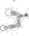
- FIG. 1 shows a functional schematic representation of a clock movement 1 according to the invention.
- FIG. 2 shows a schematic representation in plan view of the clock movement 1 according to the invention comprising a chronograph mechanism 10.
- FIG. 2 particularly represents the chronograph mechanism 10 in a neutral position, that is to say in a stopped state with the chronograph counters in their reference position before the chronograph mechanism is started.
- FIG. 3 illustrates the same clockwork movement 1 with the chronograph mechanism 10 in a working state of the chronograph gear train 20.
- FIG 4 illustrates the same clockwork movement 1 with the chronograph mechanism 10 in a state of stopping of the chronograph gear train 20, occurring after starting of the chronograph mechanism 10.
- FIG. 5 illustrates the same clockwork 1 with the chronograph mechanism 10 in a state of resetting the chronograph gear train 20 when the chronograph mechanism reset control is pressed.
- the clockwork movement 1 conventionally comprises a plate 2 serving as a support for the various elements of the clockwork movement 1, in particular for a time train 100 dedicated to the division of time which is driven by a main energy source 150.
- the energy source 150 is for example a barrel constituting an energy reserve to power the time train.
- the time gear 100 drives the displays of a time display, for example an hour hand 111 cooperating with an hour scale, a minute hand 112 cooperating with a minute scale and a second hand 113, or second hand, cooperating with a seconds graduation.
- the 100 hour gear is conventionally regulated by a 120 regulating organ.
- the regulating organ 120 traditionally comprises an oscillator 121 and an escapement 122.
- the oscillator 121 can be a mechanical or electrical oscillator.
- oscillator 121 is a mechanical oscillator of the sprung balance type.
- a sprung balance has, for example, an oscillation frequency of between 2.5 and 4 Hz.
- oscillator 121 is a high-frequency mechanical or electrical oscillator, i.e. oscillating at a frequency greater than 4Hz.
- oscillator 121 is a high-frequency mechanical or electrical oscillator, i.e. oscillating at a frequency greater than or equal to 5 Hz.
- the chronograph mechanism 10 comprises a chronograph gear train 20 which can be kinematically connected, and on request, with the time gear train 100, by means of a clutch 50 controlled by a chronograph start/stop control device 30.
- the chronograph start/stop control device 30 is configured to couple on demand the chronograph gear train 20 to the regulating organ 120, or to the time gear train 100, to regulate the chronograph gear train 20 from the regulating organ 120 of the timepiece movement 1.
- the chronograph start/stop control device 30 comprises a start/stop control member 31 which can be manipulated by the user and a clutch lever 51 controlled via the actuation of the start/stop control member 31.
- the chronograph gear train 20 is driven by a dedicated secondary energy source 35, different from the main energy source 150 of the time gear train 100.
- the entire chronograph gear train 20 is powered by a secondary energy source 35, independently of the main energy source 150 actuating the time gear train 100.
- the secondary energy source 35 is for example a barrel constituting an energy reserve to power the chronograph gear train 20.
- the chronograph gear train 20 comprises at least one chronograph counter, preferably a fraction-of-a-second counter 23 or foudroyante counter, for displaying fractions of a second.
- the chronograph gear train 20 may also include a second chronograph counter, and possibly a third chronograph counter.
- the second chronograph counter is for example a 22 seconds counter
- the third chronograph counter is for example a 21 minutes counter.
- the chronograph gear train 20 may also include an hour counter without departing from the scope of the invention.
- the fractional second counter 23 comprises a counter wheel, here called a foudroyante wheel 231, coupled to a fractional second counter shaft, driving a fractional second display 234, for example a needle, also called a foudroyante needle.
- the minute counter 21 includes a minute counter wheel 211 coupled to a minute counter shaft, driving a chronograph minute display 214, for example a hand as shown in the figure 1 .
- the 22 second counter has a counter wheel seconds 221 coupled to a seconds counter shaft, driving a chronograph seconds display 224, for example a hand.
- the seconds counter 22 is superimposed with the fractions of a second counter 23, so that the fractions of a second counter tree is merged with the seconds counter tree.
- the seconds counter 22 is schematically represented in dotted lines so as not to mask the fractions of a second counter 23.
- another configuration is possible without departing from the context of the invention.
- the minute counter wheel 211 and the second counter wheel 221 are frictionally mounted on their respective shafts.
- the chronograph gear train 20 may include intermediate chronograph wheels 24, 25, 26 to obtain the desired ratios between the different counters 21, 22, 23 of the chronograph mechanism 10.
- the chronograph gear train 20 may include more intermediate wheels depending on the needs and architectures of the timepiece movement 1, as well as the location of the different chronograph counters on the plate 2.
- the clutch 50 is a differential clutch cooperating with the clutch lever 51, the clutch lever making it possible to block one of the inputs of the differential clutch on demand depending on the running or stopping state of the chronograph.
- the clutch rocker 51 is configured to block one of the inputs of the differential clutch 50 via an intermediate clutch wheel 53 meshed with the differential clutch 50.
- the clutch can be a rocking clutch allowing the pivoting of an intermediate clutch wheel 53.
- the clutch is a vertical clutch.
- the clutch 50 also includes a drive assembly configured to rotate the output wheel at said rotational speed. of the first input wheel, when the second input wheel is locked in rotation via the clutch rocker 51.
- the clutch 50 is a ball differential clutch.
- the drive assembly is formed by the cooperation of balls and an elastic element, formed by a spring washer, ensuring the rolling without slipping of the balls on the first input wheel and the output wheel.
- the chronograph start/stop control device 30 comprises a column wheel 63 for controlling the various levers depending on the start or stop state of the chronograph.
- the chronograph start/stop control member 31 is configured to set the column wheel 63 in motion each time the user presses it, such that each press of the chronograph start/stop control member 31 causes the column wheel 63 to rotate by one step.
- the different angular positions of the column wheel 63 make it possible to coordinate the movements of the different levers, levers, etc. of the chronograph mechanism 10 for starting and stopping the chronograph gear train 20, as well as to allow the different displays 214, 224, 234 of the counters 21, 22, 23 of the chronograph mechanism 10 to be reset to zero.
- the different angular positions of the column wheel 63 make it possible to control the clutch lever 51 between a non-activated position in which the clutch lever 51 is not in contact with the intermediate clutch wheel 53 and an activated position in which the clutch lever 51 blocks the rotation of the intermediate clutch wheel 53, and therefore the second idle input wheel of the clutch 50.
- the clutch lever 51 comprises a first end 511 configured to cooperate with the column wheel 63, and particularly to sense the position of the column wheel 63 by sensing the presence of a column 631 or an inter-column space 632 of the column wheel 63, and a second end 512, in the form of a beak, configured to cooperate with the teeth of the intermediate clutch wheel 53 depending on the position of the first end 511 on a column 631 or in an inter-column space 632.
- the clutch rocker 51 switches between the non-activated position (shown in figure 1 ) in which the first end 511 is in contact with a column 631 and the second end 512 is at a distance from the intermediate clutch wheel 53, and the activated position (illustrated in figure 2 ) in which the first end 511 of the clutch rocker 51 is housed in an inter-column space 632 and the second end 512 is inserted between two consecutive teeth of the intermediate clutch wheel 53, to block the rotation of the intermediate clutch wheel 53 meshed with the clutch 50.
- the clutch rocker 51 cooperates with an elastic member 54 configured to ensure contact of the first end 511 of the clutch rocker 51 with the column wheel 63.
- the chronograph mechanism 10 comprises a mechanism 40 for resetting the counters 21, 22, 23 of the chronograph train 20, and more particularly the displays 214, 224, 234 associated respectively with these counters 21, 22, 23.
- the reset mechanism 40 comprises reset members 215, 225 secured to the shafts of the chronograph counters 21, 22.
- the reset members 215, 225 conventionally cooperate with one or more hammers (not shown) allowing them to be positioned in a reference position and the reset of the displays 214, 224 of the counters 21, 22.
- the reset organs 215, 225 of the minute counters 21 and seconds counters 22 are, for example, reset cams in the shape of a snail, heart, or other, the shape of which allows repositioning in a reference position of the displays 214, 224, at the end of the stroke of the hammer(s).
- the reset mechanism 40 comprises a reset control 60 which can be manipulated by the user, for example via a push button or an actuating pin 61.
- the reset control 60 is rotatable about an axis of rotation 66 between a neutral rest position and a reset position allowing the reset of the displays 214, 224, 234.
- the reset command 60 cooperates directly or indirectly with the reset hammer or hammers to enable the reset of the displays 214, 224 of the associated counters 21, 22.
- the reset command to 60 cooperates directly or indirectly with a lightning trigger 70 for resetting the fraction-second display 234 of the fraction-second counter 23.
- the reset control 60 can be actuated by the user only when the chronograph is stopped, that is to say when the chronograph gear train 20 is stopped, and when the column wheel 63 is in a certain angular position allowing the reset control 60 to tilt.
- the reset control 60 cooperates with an elastic reset element 62 configured to reposition the reset control 60 in a neutral rest position between each user request.
- the repositioning of the reset control 60, under the elastic effect of the elastic reset element 62, causes the hammer(s) to be repositioned in their neutral position.
- the chronograph mechanism 10 includes a foudroyante lever 70 configured to interact with the fraction-of-second counter 23.
- the reset command to 60 cooperates directly or indirectly with a lightning trigger 70 for resetting the fraction-second display 234 of the fraction-second counter 23.
- the foudroyante lever 70 is configured to cooperate with the start/stop control device 30 so as to control the angular position of the foudroyante lever 70 as a function of the running or stopping of the chronograph gear train 20 and therefore the running or stopping of the fraction-of-a-second counter 23.
- the lightning trigger 70 is also configured to cooperate with the reset control 60 to allow a reset of the fraction-second counter 23, and more particularly of the fraction-second display 234 when the reset control 60 is actuated.
- the lightning lever 70 has a dual function.
- a first function consists in holding the fraction-of-a-second display 234 in position when the chronograph is stopped and a second function consists in ensuring repositioning of the fraction-of-a-second display 234 in the reference position when the chronograph is reset to zero by actuating the reset control 60.
- the lightning rocker 70 is rotatable about an axis of rotation 76.
- the position of the axis of rotation 76 can be adjusted by means of an eccentric.
- the chronograph mechanism 10 is configured to angularly position the foudroyante lever 70 in three positions providing three different actions. These three positions will be described in more detail in the rest of the description.
- the lightning lever 70 comprises a first arm 71 configured to cooperate with the chronograph start/stop control device 30 and sense the different states of the start/stop control device 30.
- the first arm 71 has a free end forming a feeler cooperating with the column wheel 63 of the chronograph start/stop control device 30 to position the foudroyante lever 70 in two stable positions which form two of the three positions of the foudroyante lever 70.
- the feeler of the first arm 71 is positioned in an inter-column space 632 of the column wheel 63, as visible in figures 1 , 3 And 4 , when the chronograph gear train 20 is stopped.
- This position defines the first stable position of the foudroyante lever 70 occurring at the same time as the stopping of the chronograph mechanism 10.
- the lightning lever 70 comprises a second arm 72, extending substantially opposite the first arm 71 relative to the axis of rotation 76.
- the second arm 72 comprises an end beak 720 configured to cooperate and block the rotation of the fraction-of-second counter 23, and more particularly the lightning wheel 231 of the fraction-of-second counter 23.
- the lightning wheel 231 is blocked in rotation by the end beak 720 of the second arm 72 of the lightning lever 70 which is inserted between two consecutive teeth of the toothing 233 of the lightning wheel 231.
- the lightning wheel 231 is free and can be rotated by the chronograph gear train 20 so as to count fractions of a second.
- the change of position, between the stop and neutral position, of the lightning lever 70 is controlled by the column wheel 63, itself driven in rotation with each request of the chronograph start/stop control member 31.
- the lightning wheel 231 has an asymmetrical toothing 233, also called wolf toothing.
- the teeth of the lightning wheel 231 are composed of a series of identical teeth forming a regular toothing and a long tooth 232, that is to say having a greater height than the other teeth of the toothing 233.
- the long tooth 232 extends radially beyond the regular toothing of the lightning wheel 231.
- the lightning lever 70 comprises a third arm 73 configured to cooperate directly or indirectly with the reset control 60 and position the lightning lever 70 in a third position, called intermediate, illustrated more particularly in FIG. figure 4 .
- This third intermediate position of the lightning lever 70 is not a stable position but a position imposed by the angular position of the reset control 60 when it is held partially or completely pressed by the user in the reset position.
- This third arm 73 is used as a lever by the reset control 60 to position the foudroyante lever 70 in the intermediate position located angularly between the stop position and the neutral position. This intermediate position can only be reached from the stable stop position of the foudroyante lever 70 locking the foudroyante counter 23 in position when the chronograph is stopped.
- the end beak 720 is radially further from the center of rotation of the lightning wheel 231 than in the stop position of the lightning lever 70.
- the end beak 720 is therefore disengaged from the regular toothing of the lightning wheel 231, allowing a rotation of the lightning wheel 231, but is in a position sufficiently close to the periphery of the lightning wheel 231 to be on the path of the long tooth 232 and thus to be able to interact with the long tooth 232 to block the rotation of the lightning wheel 231 in a particular position, the reference position.
- the end beak 720 allows a partial rotation of the lightning wheel 231, that is to say less than a complete turn, until positioning the lightning wheel 231 in the reference position.
- the end beak 720 of the lightning lever 70 constitutes a positioning stop preventing the passage of the long tooth 232 beyond the end beak 720, during the rotation of the lightning wheel 231.
- the lightning wheel 231 is maintained in its reference position which corresponds to the zero position of the fractions of a second display 234.
- the reset control 60 has means configured to cooperate with the lightning rocker 70, and more particularly with the third arm 73.
- the reset control 60 comprises a recess 67 configured to receive, guide and partially house the third arm 73 and act on it.
- the contacting of the reset control 60 with the third arm 73 is accompanied by a rotation of the lightning rocker 70 towards its neutral position so as to move the end beak 720 away from the regular toothing of the lightning wheel 231 and from the center of rotation of the lightning wheel 231, as indicated above.
- the lightning rocker 70 cooperates with a lightning elastic member 80 configured to return the lightning rocker 70 to its stop position.
- the elastic foudroyante member 80 tends to position the end beak 720 in its stop position, that is to say inserted between two consecutive teeth of the toothing 233, to hold the foudroyante wheel 231 in position until the next start of the chronograph mechanism 10.
- the reset mechanism 40 also includes a retaining member 64 for securing the reset mechanism 40 and ensuring full actuation of the hammer(s) to their reset position.
- the retaining member 64 is configured to momentarily retain actuation of the zeroing control 60, and therefore of the hammer(s), as long as a certain force is not applied to the zeroing control 60.
- the retaining member 64 is a safety member preventing an unwanted resetting of the various displays 214, 224, 234 of the counters 21, 22, 23 of the chronograph mechanism 10.
- the retaining member 64 is a safety member preventing an unwanted resetting of the various displays 214, 224, 234 of the counters 21, 22, 23 of the chronograph mechanism 10.
- retainer 64 exhibits dynamic behavior similar to a mechanical fuse.
- the retaining member 64 comprises a portion secured to the plate 2 and an elastic portion arranged to exert the retaining force against the actuation of the zero-reset control 60.
- the elastic portion is configured to deform when a force greater than the retaining force is applied to the zero-reset control 60, thereby releasing the complete movement of the zero-reset control 60 allowing the movement of the hammer to its zero-reset position ( figure 4 ).
- the reset control 60 comprises, for example, a stud 65 intended to bear on the elastic portion of the retaining member 64.
- the stud 65 is supported at the level of a retaining notch provided at the level of the free end of the elastic portion of the retaining member 64.
- the retaining notch has a retaining surface and a tilting point beyond which the retaining member 64 allows the rapid and clear actuation of the reset control 60, thus allowing the hammer(s) to be fully actuated until the hammer(s) come into contact with the reset cams 215, 225 of the chronograph counters 21, 22 and the repositioning of these cams in their reference position.
- the release of the reset control 60 also actuates the lightning rocker 70 generating a slight rotation towards its neutral position, which slightly separates the end beak 720 of the second arm 72 from the regular toothing of the lightning wheel 231.
- the released lightning wheel 231 continues its rotation in the direction of travel while consuming energy from the energy reserve.
- the lightning lever 70 particularly the third arm 73, and the reset control 60 are configured to first actuate the lightning lever 70 before the hammer(s) come into contact with the reset cams 215, 225. counters 21, 22, so as to ensure a complete reset of the fractions of a second display 234 before the complete reset of the seconds 224 and minutes 214 displays via the hammer(s).
- a first request of the chronograph start/stop control 31 makes it possible to start the chronograph gear train 20 of the chronograph mechanism 10 in the following manner.
- a request to the chronograph start/stop control member 31 causes it to pivot about its axis of rotation, the latter causing the column wheel 63 to rotate by one step, here in the counterclockwise direction, thus modifying the arrangement of the inter-column spaces 632 and the columns 631 of the column wheel 63 relative to the different levers of the chronograph mechanism 10.
- clutch lever 51 swings from its deactivated position (shown in figure 1 ) to its activated position (shown in the figure 2 ) so as to block the rotation of the intermediate clutch wheel 53, inducing a blocking of the second idle input wheel of the clutch 50.
- Blocking the second idle input wheel of clutch 50 makes it possible to couple chronograph gear train 20 to time gear train 100 of clockwork movement 1, setting the chronograph gear train in motion at the rate of regulating organ 120.
- the rotation of the column wheel 63 causes the lightning lever 70 to tilt, which passes from its first stable position (stop position) (illustrated in figure 1 ) in which the feeler of the first arm 71 is in an inter-column space 632 of the wheel with columns 63 and the end beak 720 of the second arm 72 is inserted between two consecutive teeth of the toothing 233 of the lightning wheel 231, at its second stable position (neutral position) (illustrated in figure 2 ) in which the feeler of the first arm 71 is in contact with a column 631 of the column wheel 63 releasing the end beak 720 of the toothing 233 of the lightning wheel 231.
- the various counters 21, 22, 23 of the chronograph gear train 20 are free and driven in rotation at the rate of the regulating organ of the clockwork movement 1 by the coupling to the time gear train 100.
- the feeler of the first arm 71 of the lightning lever 70 passes through an inter-column space 632 of the column wheel 63 positioning the lightning lever 70 in its first stable position (stop position) under the effect of the resilient lightning member 80, in which the end beak 720 is inserted between two consecutive teeth of the toothing 233 of the lightning wheel 231 thus blocking the position of the fraction-of-second display 234.
- Additional conventional means can also be provided to maintain in position the displays 214, 224 of the various counters 21, 22 of the chronograph mechanism 10 in this stopped state of the chronograph.
- Such means can be controlled by the column wheel 63 by means of additional levers interacting with the various columns 631 and inter-column spaces 632.
- the user can restart the chronograph by activating the chronograph start/stop control member 31 a third time, again causing the chronograph gear train 20 to start as described previously with the corresponding pivoting of the levers.
- the user can also reset the various counters 21, 22, 23 of the chronograph gear train 20 by requesting the reset command 60, this reset being permitted by the position of the column wheel 63.
- the complete movement of the reset control 60 makes it possible to modify the position of the foudroyante lever 70 so as to position it in its third intermediate position allowing a return to zero of the fractions of a second display 234, the foudroyante wheel 231 performing a rotation driven by the second energy source 35 of the chronograph gear train 20 until the long tooth 232 comes into contact with the end beak 720 of the second arm 72 of the foudroyante lever 70.
- the complete movement of the reset control 60 drives the hammer(s) of the chronograph mechanism 10 to strike the various reset organs 215, 225 to return to the reference position the various displays 214, 224 corresponding to the chronograph mechanism 10.
- actuation of the reset control 60 can release the means for holding the displays 214, 224 of the counters 21, 22 in position.
- the reset control 60 When the reset control 60 is released, it returns to the neutral position under the effect of the elastic member 62, returning the hammer(s) to the neutral position, optionally repositioning the means for holding the displays 214, 224 of the counters 21, 22 in position to ensure that these displays 214, 224 are held in position, releases its stress exerted on the lightning lever 70 which, under the action of the lightning elastic member 80, repositions the end beak 720 between two consecutive teeth of the toothing 233 of the lightning wheel 231 to ensure that the lightning wheel 231 is held in position and thus avoid undesirable effects of fluctuation of the fractions of a second display 234 while waiting for the next start of the chronograph mechanism 10.
- the chronograph mechanism 10 has been shown and described with a column wheel 63 to control the different movements of the different levers which are supported against a column or between two columns.
- the chronograph mechanism 10 can also be a chronograph mechanism with cams replacing the column wheel 63 without departing from the context of the invention, to control the different states of the chronograph.
- the invention has been particularly described with a counter of fractions of a second. However, the invention is also applicable for a counter of seconds, minutes or hours without departing from the scope of the invention.
- the invention also relates to a timepiece, for example example a wristwatch, including such a clockwork movement.
Landscapes
- Physics & Mathematics (AREA)
- General Physics & Mathematics (AREA)
- Measurement Of Unknown Time Intervals (AREA)
Priority Applications (4)
| Application Number | Priority Date | Filing Date | Title |
|---|---|---|---|
| EP23168492.9A EP4451066B1 (de) | 2023-04-18 | 2023-04-18 | Uhrwerk, das einen chronographenmechanismus umfasst, insbesondere mit sekundenbruchteilen |
| US18/594,364 US20240353800A1 (en) | 2023-04-18 | 2024-03-04 | Horological movement comprising a chronograph mechanism, in particular a jumping-second mechanism |
| JP2024034838A JP7680592B2 (ja) | 2023-04-18 | 2024-03-07 | クロノグラフ機構、特にジャンピングセコンド機構を備える時計ムーブメント |
| CN202410468103.4A CN118818945A (zh) | 2023-04-18 | 2024-04-18 | 包括计时机构、特别是跳秒机构的钟表机芯 |
Applications Claiming Priority (1)
| Application Number | Priority Date | Filing Date | Title |
|---|---|---|---|
| EP23168492.9A EP4451066B1 (de) | 2023-04-18 | 2023-04-18 | Uhrwerk, das einen chronographenmechanismus umfasst, insbesondere mit sekundenbruchteilen |
Publications (2)
| Publication Number | Publication Date |
|---|---|
| EP4451066A1 true EP4451066A1 (de) | 2024-10-23 |
| EP4451066B1 EP4451066B1 (de) | 2026-04-01 |
Family
ID=86053816
Family Applications (1)
| Application Number | Title | Priority Date | Filing Date |
|---|---|---|---|
| EP23168492.9A Active EP4451066B1 (de) | 2023-04-18 | 2023-04-18 | Uhrwerk, das einen chronographenmechanismus umfasst, insbesondere mit sekundenbruchteilen |
Country Status (4)
| Country | Link |
|---|---|
| US (1) | US20240353800A1 (de) |
| EP (1) | EP4451066B1 (de) |
| JP (1) | JP7680592B2 (de) |
| CN (1) | CN118818945A (de) |
Citations (2)
| Publication number | Priority date | Publication date | Assignee | Title |
|---|---|---|---|---|
| CH703797B1 (fr) | 2007-03-09 | 2012-03-30 | Richemont Int Sa | Pièce d'horlogerie comportant un chronographe et une foudroyante. |
| EP3059642A1 (de) * | 2015-02-23 | 2016-08-24 | Montres Breguet S.A. | Uhrmechanismus |
Family Cites Families (4)
| Publication number | Priority date | Publication date | Assignee | Title |
|---|---|---|---|---|
| CH682034B5 (fr) * | 1991-10-14 | 1994-01-14 | Eta S.A. Fabriques D'ebauches | Pièce d'horlogerie comportant un module de chronographe adapté sur un module moteur. |
| ATE392679T1 (de) * | 2002-06-13 | 2008-05-15 | Vaucher Mft Fleurier Sa | Chronograph-mechanismus |
| ATE316663T1 (de) * | 2002-10-07 | 2006-02-15 | Vaucher Mft Fleurier Sa | Chronographenuhrwerk |
| US7597471B2 (en) * | 2005-11-24 | 2009-10-06 | Vaucher Manufacture Fleurier S.A. | Time piece chronograph clockwork movement |
-
2023
- 2023-04-18 EP EP23168492.9A patent/EP4451066B1/de active Active
-
2024
- 2024-03-04 US US18/594,364 patent/US20240353800A1/en active Pending
- 2024-03-07 JP JP2024034838A patent/JP7680592B2/ja active Active
- 2024-04-18 CN CN202410468103.4A patent/CN118818945A/zh active Pending
Patent Citations (2)
| Publication number | Priority date | Publication date | Assignee | Title |
|---|---|---|---|---|
| CH703797B1 (fr) | 2007-03-09 | 2012-03-30 | Richemont Int Sa | Pièce d'horlogerie comportant un chronographe et une foudroyante. |
| EP3059642A1 (de) * | 2015-02-23 | 2016-08-24 | Montres Breguet S.A. | Uhrmechanismus |
Also Published As
| Publication number | Publication date |
|---|---|
| JP2024154372A (ja) | 2024-10-30 |
| CN118818945A (zh) | 2024-10-22 |
| US20240353800A1 (en) | 2024-10-24 |
| JP7680592B2 (ja) | 2025-05-20 |
| EP4451066B1 (de) | 2026-04-01 |
Similar Documents
| Publication | Publication Date | Title |
|---|---|---|
| EP3021175B1 (de) | Rattrapantenmechanismus mit planetengetriebe für uhren | |
| EP2453322B1 (de) | Schneller Korrektor einer Zeitgrößenanzeige für Uhr | |
| EP0772104A1 (de) | Uhr mit Chronographmechanismus | |
| EP3059643B1 (de) | Uhrmechanismus | |
| EP3059642B1 (de) | Uhrmechanismus | |
| CH716841A1 (fr) | Mouvement d'horlogerie à chronographe. | |
| CH703361A2 (fr) | Mouvement horloger presentant des fonctions de chronographe et de compte-a-rebours. | |
| EP3368950B1 (de) | Chronograph mit rückwärtszähler | |
| WO2018114613A1 (fr) | Mouvement pour piece d'horlogerie | |
| EP4451066A1 (de) | Uhrwerk, das einen chronographenmechanismus umfasst, insbesondere mit sekundenbruchteilen | |
| CH697433B1 (fr) | Pièce d'horlogerie avec mécanisme chronographe. | |
| CH720711A2 (fr) | Mouvement d'horlogerie comportant un mécanisme de chronographe, notamment à seconde foudroyante | |
| EP3770693B1 (de) | Anschlagmechanismus für uhrenkäfig mit anschlagrad | |
| EP4254079B1 (de) | Mechanismus zur anzeige der mondphasen für uhr | |
| EP3252543B1 (de) | Anzeigevorrichtung für uhrwerk | |
| CH527462A (fr) | Montre-chronographe | |
| CH699056B1 (fr) | Mouvement pour pièce d'horlogerie à remontoir d'égalité | |
| EP4390574A1 (de) | Chronographenmechanismus für uhrwerk und uhr mit einem solchen mechanismus | |
| CH720361A2 (fr) | Mécanisme de chronographe pour mouvement d'horlogerie | |
| CH720089B1 (fr) | Mobile pour un mécanisme horloger, mécanisme horloger, mouvement horloger, et pièce d'horlogerie correspondants | |
| EP1960843A2 (de) | Uhrenmechanismus | |
| CH524853A (fr) | Montre-bracelet chronographe | |
| EP4421567A1 (de) | Auslösemechanismus eines uhrwerksmechanismus und uhr mit solch einem auslösemechanismus | |
| CH719556A2 (fr) | Mécanisme d'affichage des phases de lune de pièce d'horlogerie | |
| CH718021B1 (fr) | Mécanisme d'affichage d'information, mouvement et pièce d'horlogerie |
Legal Events
| Date | Code | Title | Description |
|---|---|---|---|
| PUAI | Public reference made under article 153(3) epc to a published international application that has entered the european phase |
Free format text: ORIGINAL CODE: 0009012 |
|
| STAA | Information on the status of an ep patent application or granted ep patent |
Free format text: STATUS: THE APPLICATION HAS BEEN PUBLISHED |
|
| AK | Designated contracting states |
Kind code of ref document: A1 Designated state(s): AL AT BE BG CH CY CZ DE DK EE ES FI FR GB GR HR HU IE IS IT LI LT LU LV MC ME MK MT NL NO PL PT RO RS SE SI SK SM TR |
|
| P01 | Opt-out of the competence of the unified patent court (upc) registered |
Free format text: CASE NUMBER: APP_59123/2024 Effective date: 20241030 |
|
| STAA | Information on the status of an ep patent application or granted ep patent |
Free format text: STATUS: REQUEST FOR EXAMINATION WAS MADE |
|
| 17P | Request for examination filed |
Effective date: 20250423 |
|
| GRAP | Despatch of communication of intention to grant a patent |
Free format text: ORIGINAL CODE: EPIDOSNIGR1 |
|
| STAA | Information on the status of an ep patent application or granted ep patent |
Free format text: STATUS: GRANT OF PATENT IS INTENDED |
|
| RIC1 | Information provided on ipc code assigned before grant |
Ipc: G04F 7/08 20060101AFI20250814BHEP |
|
| INTG | Intention to grant announced |
Effective date: 20250822 |
|
| GRAJ | Information related to disapproval of communication of intention to grant by the applicant or resumption of examination proceedings by the epo deleted |
Free format text: ORIGINAL CODE: EPIDOSDIGR1 |
|
| STAA | Information on the status of an ep patent application or granted ep patent |
Free format text: STATUS: REQUEST FOR EXAMINATION WAS MADE |
|
| INTC | Intention to grant announced (deleted) | ||
| GRAS | Grant fee paid |
Free format text: ORIGINAL CODE: EPIDOSNIGR3 |
|
| STAA | Information on the status of an ep patent application or granted ep patent |
Free format text: STATUS: GRANT OF PATENT IS INTENDED |
|
| GRAP | Despatch of communication of intention to grant a patent |
Free format text: ORIGINAL CODE: EPIDOSNIGR1 |
|
| GRAJ | Information related to disapproval of communication of intention to grant by the applicant or resumption of examination proceedings by the epo deleted |
Free format text: ORIGINAL CODE: EPIDOSDIGR1 |
|
| STAA | Information on the status of an ep patent application or granted ep patent |
Free format text: STATUS: REQUEST FOR EXAMINATION WAS MADE |
|
| GRAS | Grant fee paid |
Free format text: ORIGINAL CODE: EPIDOSNIGR3 |
|
| STAA | Information on the status of an ep patent application or granted ep patent |
Free format text: STATUS: GRANT OF PATENT IS INTENDED |
|
| GRAP | Despatch of communication of intention to grant a patent |
Free format text: ORIGINAL CODE: EPIDOSNIGR1 |
|
| INTG | Intention to grant announced |
Effective date: 20251110 |
|
| INTC | Intention to grant announced (deleted) | ||
| INTG | Intention to grant announced |
Effective date: 20251119 |
|
| GRAA | (expected) grant |
Free format text: ORIGINAL CODE: 0009210 |
|
| STAA | Information on the status of an ep patent application or granted ep patent |
Free format text: STATUS: THE PATENT HAS BEEN GRANTED |
|
| AK | Designated contracting states |
Kind code of ref document: B1 Designated state(s): AL AT BE BG CH CY CZ DE DK EE ES FI FR GB GR HR HU IE IS IT LI LT LU LV MC ME MK MT NL NO PL PT RO RS SE SI SK SM TR |
|
| REG | Reference to a national code |
Ref country code: CH Ref legal event code: F10 Free format text: ST27 STATUS EVENT CODE: U-0-0-F10-F00 (AS PROVIDED BY THE NATIONAL OFFICE) Effective date: 20260401 Ref country code: GB Ref legal event code: FG4D Free format text: NOT ENGLISH |
|
| REG | Reference to a national code |
Ref country code: CH Ref legal event code: R17 Free format text: ST27 STATUS EVENT CODE: U-0-0-R10-R17 (AS PROVIDED BY THE NATIONAL OFFICE) Effective date: 20260413 |
|
| REG | Reference to a national code |
Ref country code: DE Ref legal event code: R096 Ref document number: 602023014300 Country of ref document: DE |
|
| REG | Reference to a national code |
Ref country code: IE Ref legal event code: FG4D Free format text: LANGUAGE OF EP DOCUMENT: FRENCH |