EP4451005A1 - Steuerungsverfahren für lidar und mehrkanal-lidar - Google Patents
Steuerungsverfahren für lidar und mehrkanal-lidar Download PDFInfo
- Publication number
- EP4451005A1 EP4451005A1 EP22905808.6A EP22905808A EP4451005A1 EP 4451005 A1 EP4451005 A1 EP 4451005A1 EP 22905808 A EP22905808 A EP 22905808A EP 4451005 A1 EP4451005 A1 EP 4451005A1
- Authority
- EP
- European Patent Office
- Prior art keywords
- pulses
- ranging
- lasers
- channels
- pulse
- Prior art date
- Legal status (The legal status is an assumption and is not a legal conclusion. Google has not performed a legal analysis and makes no representation as to the accuracy of the status listed.)
- Pending
Links
- 238000000034 method Methods 0.000 title claims abstract description 45
- 238000001514 detection method Methods 0.000 claims abstract description 72
- 238000010586 diagram Methods 0.000 description 24
- 238000005259 measurement Methods 0.000 description 11
- 238000013459 approach Methods 0.000 description 7
- 230000003287 optical effect Effects 0.000 description 7
- 230000008569 process Effects 0.000 description 6
- 230000000694 effects Effects 0.000 description 5
- 230000008859 change Effects 0.000 description 4
- 238000002592 echocardiography Methods 0.000 description 4
- 230000002452 interceptive effect Effects 0.000 description 4
- 230000000116 mitigating effect Effects 0.000 description 4
- 238000002310 reflectometry Methods 0.000 description 4
- 238000004891 communication Methods 0.000 description 2
- 238000006243 chemical reaction Methods 0.000 description 1
- 238000013480 data collection Methods 0.000 description 1
- 230000003247 decreasing effect Effects 0.000 description 1
- 238000005516 engineering process Methods 0.000 description 1
- 230000006872 improvement Effects 0.000 description 1
- 238000009434 installation Methods 0.000 description 1
- 230000003993 interaction Effects 0.000 description 1
- 230000000670 limiting effect Effects 0.000 description 1
- 238000012986 modification Methods 0.000 description 1
- 230000004048 modification Effects 0.000 description 1
- 230000005693 optoelectronics Effects 0.000 description 1
- 238000012545 processing Methods 0.000 description 1
- 230000002829 reductive effect Effects 0.000 description 1
- 230000004044 response Effects 0.000 description 1
- 230000003068 static effect Effects 0.000 description 1
- 238000006467 substitution reaction Methods 0.000 description 1
Images


Classifications
-
- G—PHYSICS
- G01—MEASURING; TESTING
- G01S—RADIO DIRECTION-FINDING; RADIO NAVIGATION; DETERMINING DISTANCE OR VELOCITY BY USE OF RADIO WAVES; LOCATING OR PRESENCE-DETECTING BY USE OF THE REFLECTION OR RERADIATION OF RADIO WAVES; ANALOGOUS ARRANGEMENTS USING OTHER WAVES
- G01S17/00—Systems using the reflection or reradiation of electromagnetic waves other than radio waves, e.g. lidar systems
- G01S17/02—Systems using the reflection of electromagnetic waves other than radio waves
- G01S17/06—Systems determining position data of a target
- G01S17/08—Systems determining position data of a target for measuring distance only
- G01S17/10—Systems determining position data of a target for measuring distance only using transmission of interrupted, pulse-modulated waves
-
- G—PHYSICS
- G01—MEASURING; TESTING
- G01S—RADIO DIRECTION-FINDING; RADIO NAVIGATION; DETERMINING DISTANCE OR VELOCITY BY USE OF RADIO WAVES; LOCATING OR PRESENCE-DETECTING BY USE OF THE REFLECTION OR RERADIATION OF RADIO WAVES; ANALOGOUS ARRANGEMENTS USING OTHER WAVES
- G01S17/00—Systems using the reflection or reradiation of electromagnetic waves other than radio waves, e.g. lidar systems
- G01S17/02—Systems using the reflection of electromagnetic waves other than radio waves
- G01S17/06—Systems determining position data of a target
- G01S17/42—Simultaneous measurement of distance and other co-ordinates
-
- G—PHYSICS
- G01—MEASURING; TESTING
- G01S—RADIO DIRECTION-FINDING; RADIO NAVIGATION; DETERMINING DISTANCE OR VELOCITY BY USE OF RADIO WAVES; LOCATING OR PRESENCE-DETECTING BY USE OF THE REFLECTION OR RERADIATION OF RADIO WAVES; ANALOGOUS ARRANGEMENTS USING OTHER WAVES
- G01S17/00—Systems using the reflection or reradiation of electromagnetic waves other than radio waves, e.g. lidar systems
- G01S17/87—Combinations of systems using electromagnetic waves other than radio waves
-
- G—PHYSICS
- G01—MEASURING; TESTING
- G01S—RADIO DIRECTION-FINDING; RADIO NAVIGATION; DETERMINING DISTANCE OR VELOCITY BY USE OF RADIO WAVES; LOCATING OR PRESENCE-DETECTING BY USE OF THE REFLECTION OR RERADIATION OF RADIO WAVES; ANALOGOUS ARRANGEMENTS USING OTHER WAVES
- G01S17/00—Systems using the reflection or reradiation of electromagnetic waves other than radio waves, e.g. lidar systems
- G01S17/88—Lidar systems specially adapted for specific applications
- G01S17/93—Lidar systems specially adapted for specific applications for anti-collision purposes
- G01S17/931—Lidar systems specially adapted for specific applications for anti-collision purposes of land vehicles
-
- G—PHYSICS
- G01—MEASURING; TESTING
- G01S—RADIO DIRECTION-FINDING; RADIO NAVIGATION; DETERMINING DISTANCE OR VELOCITY BY USE OF RADIO WAVES; LOCATING OR PRESENCE-DETECTING BY USE OF THE REFLECTION OR RERADIATION OF RADIO WAVES; ANALOGOUS ARRANGEMENTS USING OTHER WAVES
- G01S7/00—Details of systems according to groups G01S13/00, G01S15/00, G01S17/00
- G01S7/48—Details of systems according to groups G01S13/00, G01S15/00, G01S17/00 of systems according to group G01S17/00
- G01S7/481—Constructional features, e.g. arrangements of optical elements
- G01S7/4814—Constructional features, e.g. arrangements of optical elements of transmitters alone
- G01S7/4815—Constructional features, e.g. arrangements of optical elements of transmitters alone using multiple transmitters
-
- G—PHYSICS
- G01—MEASURING; TESTING
- G01S—RADIO DIRECTION-FINDING; RADIO NAVIGATION; DETERMINING DISTANCE OR VELOCITY BY USE OF RADIO WAVES; LOCATING OR PRESENCE-DETECTING BY USE OF THE REFLECTION OR RERADIATION OF RADIO WAVES; ANALOGOUS ARRANGEMENTS USING OTHER WAVES
- G01S7/00—Details of systems according to groups G01S13/00, G01S15/00, G01S17/00
- G01S7/48—Details of systems according to groups G01S13/00, G01S15/00, G01S17/00 of systems according to group G01S17/00
- G01S7/483—Details of pulse systems
- G01S7/484—Transmitters
-
- G—PHYSICS
- G01—MEASURING; TESTING
- G01S—RADIO DIRECTION-FINDING; RADIO NAVIGATION; DETERMINING DISTANCE OR VELOCITY BY USE OF RADIO WAVES; LOCATING OR PRESENCE-DETECTING BY USE OF THE REFLECTION OR RERADIATION OF RADIO WAVES; ANALOGOUS ARRANGEMENTS USING OTHER WAVES
- G01S7/00—Details of systems according to groups G01S13/00, G01S15/00, G01S17/00
- G01S7/48—Details of systems according to groups G01S13/00, G01S15/00, G01S17/00 of systems according to group G01S17/00
- G01S7/483—Details of pulse systems
- G01S7/486—Receivers
- G01S7/4865—Time delay measurement, e.g. time-of-flight measurement, time of arrival measurement or determining the exact position of a peak
Definitions
- This disclosure relates to the technical field of optoelectronic detection and, in particular, to a control method for a LiDAR, and a multi-channel LiDAR.
- LiDAR The light detection and ranging
- the light detection and ranging is used as a three-dimensional measurement system to achieve a three-dimensional measurement coverage of the measurement region by means of the collected point cloud.
- a multi-channel LiDAR based on Time of Flight can use multiple laser emitting and receiving channels, and be suitable for situations where scanning of a large field of view and determination of a high-density point cloud is required.
- TOF Time of Flight
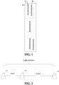
- a laser 11 denotes a laser located in the 1st row of the 1st column
- a laser 12 denotes a laser located in the 2nd row of the 1st column
- a laser 41 denotes a laser located in the 1st row of the 4th column
- the channels used for parallel detection are channel1-channel8, then 8 points with an upper ranging limit of 200 m can be generated at the time of 1.333 us.
- the 128 lasers are divided into 16 groups, each group performing parallel light emission and parallel detection. By doing so, the resolution of the point cloud is improved by a factor of eight compared to a LiDAR with only one laser emitting light at the same time point.
- the LiDAR can control the laser to emit two or more pulses.
- the second detection pulse p2 is emitted after a time interval of code1
- the third pulse p3 is emitted after another time interval of code2.
- the code1 can be set in different values. Specific interval times code1 and code2 are set above for the multi-pulses P1, P2, and P3, that is, the detection laser pulses are encoded.
- the receiving end of the LiDAR includes a receiver unit and a signal processor unit, where the receiver unit includes a detector for receiving an echo generated from the detection pulse and converting the echo into an electrical signal.
- the receiver unit includes a detector for receiving an echo generated from the detection pulse and converting the echo into an electrical signal.
- one laser and one detector form a detection channel.
- the signal processor unit is used to process the electrical signal and calculate parameters such as the distance of the obstacle and the reflectivity.
- different recognition approaches can be used to recognize whether the received echo (and the generated electrical signal) corresponds to the emitted detection pulse.
- the signal processor unit recognizes 3 pulses spaced apart from each other at intervals of code1 and code2 from the received set of pulses (there can be multiple pulses, e.g., more than 3 pulses), it can then be considered that an object is detected by this light-emitting measurement. If no 3 pulses spaced apart at intervals of code1 and code2 are recognized, it is considered that no object has been detected in this light-emitting measurement.
- This recognition approach is precise and can minimize noisy points, but it is too computationally intensive and prone to point loss.
- Another alternative approach is as follows: once 2 pulses spaced apart at intervals of code1 or code2 are recognized from the received set of pulses, it is considered that this light-emitting measurement has detected an object. This approach is less computationally intensive and prone to noisy points, but can minimize the occurrence of point loss.
- Parallel light emission and measurement of multiple channels additionally introduces the problem of optical crosstalk and electrical crosstalk.
- the optical crosstalk is the interference caused by parallel light emission of neighboring channels in a LiDAR.
- the detector of each channel can receive the reflected light on the target object generated from the detection pulses emitted from the other channels.
- the intensity of the reflected light increases with decreasing distance, and the higher the reflectivity of the target, the higher the intensity of the reflected light.
- an interfering pulse waveform can be generated on the waveform received by the detector of this channel (it can be superimposed on the echo pulse caused by the real obstacle, while the real echo pulse is the basis for the subsequent calculation of the distance and reflectivity, so the calculation of the distance and the reflectivity are both interfered with, which can result in inaccurate results).
- the optical crosstalk mentioned is the main factor affecting the ranging precision, which mostly occurs in the scenarios with highly reflective plates in the near vicinity.
- the electrical crosstalk refers to the situation where, when multiple channels in the LiDAR are receiving electrical signals at the same time, signals from the channels with stronger electrical signals can be crosstalked through the circuit directly to the rest of the receiving channels, resulting in an interfering pulse waveform.
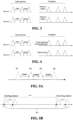
- Fig. 3 schematically shows a detection process for two channels in an ideal situation, where there is no electrical crosstalk and optical crosstalk between the two channels, or the electrical crosstalk and the optical crosstalk have been eliminated.
- the pulse emitted by the channel 1 detects an object a and the pulse emitted by the channel2 detects an object b, and when there is no optical crosstalk or electrical crosstalk between the channel1 and the channel2, the channels receive only the reflected echo pulses of the objects corresponding to their own channels, then the ranging result of the object a is calculated by the leading edge + the pulse width, and the distance of the object a can be accurately determined based on the calculation result.
- Fig. 4 schematically shows a situation where there is crosstalk between two channels.
- the pulse emitted by the channel1 detects an object a and the pulse emitted by the channel2 detects an object b.
- the channel1 emits three detection pulses Pa1, Pa2, and Pa3, and receives three echo pulses Ea1, Ea2, and Ea3 correspondingly; and the channel2 emits three detection pulses Pb1, Pb2, and Pb3, and receives three echo pulses Eb1, Eb2, and Eb3 correspondingly.
- the three echo pulses of the channel 2 can separately generate crosstalk on the channel 1, such as the crosstalk echo pulses Eb1', Eb2', and Eb3' in Fig. 4 .
- the crosstalk echo pulses Eb1', Eb2', and Eb3' are superimposed on the echo pulses Ea1, Ea2, and Ea3 of the channel1, respectively, which can result in a change in the waveform of the echo pulses Ea1, Ea2, and Ea3.
- the crosstalk echo pulses Eb1', Eb2', and Eb3' are superimposed on the echo pulses Ea1, Ea2, and Ea3 of the channel1, respectively, which can result in a change in the waveform of the echo pulses Ea1, Ea2, and Ea3.
- the final echo arrival time determined by the signal processor unit can be advanced, causing the distance of the object a to be calculated as da' from the true value da. Therefore, in the case of Fig. 4 , when the channel1 receives the echo of the object a + the echo of the object b (which should actually appear in the orientation corresponding to the channel2) (for the direction of the channel1, there is actually no object b) due to crosstalk, the echo pulse of the object a can be superimposed with the crosstalk echo pulse, resulting in a change in the leading edge and the pulse width of the object a. At this point, the ranging result of the object a is similarly calculated from the leading edge + the pulse width, but it can deviate from the result when there is no crosstalk, and the degree of deviation can depend on the degrees of deviation of the leading edge and the pulse width.
- this disclosure relates to a control method for a LiDAR, where the LiDAR includes n channels, n ⁇ 32, each channel being formed by at least one laser and at least one detector, the control method including:
- At least part of the lasers are configured to emit single pulses
- the light emission mode includes: encoding, for the lasers emitting single pulses, emission time points of the single pulses.
- At least part of the lasers are configured to emit multi-pulses, where the light emission mode includes: for the lasers emitting multi-pulses, emitting the first pulses in parallel and encoding intervals of the multi-pulses.
- the step S11 includes: predicting, based on previous ranging results of each channel, time of a ranging echo pulse corresponding to a ranging pulse to be emitted, and setting the light emission mode of lasers that are to perform detection.
- the step S11 includes: predicting, based on previous ranging results of each channel and a channel neighboring the channel as well as obstacle information, time of a ranging echo pulse corresponding to a ranging pulse to be emitted, and setting the light emission mode of lasers that are to perform detection.
- the step S11 includes:
- the step S111 further includes: dividing the second interval into k sub-intervals, where k is an integer and is greater than or equal to the number of channels in the group; and the step S113 includes: setting the light emission mode of lasers that are to perform detection to cause ranging echo pulses generated to be distributed in a non-overlapping manner in the k sub-intervals after lasers of at least part of multiple channels emitting light in parallel emit ranging pulses.
- the length of each of the sub-intervals is greater than a maximum pulse width of ranging echo pulses of the LiDAR.
- the step S113 includes: setting the light emission mode of lasers that are to perform detection to cause ranging echo pulses generated to be distributed in sub-intervals of the k sub-intervals that are unoccupied and closest in distance, after lasers of at least part of the multiple channels emitting light in parallel emit ranging pulses.
- the light emission mode is further configured to cause at least part of ranging echo pulses generated by ranging pulses emitted by lasers of each channel to not overlap with non-ranging echo pulses generated by non-ranging pulses emitted by lasers of the other channels in the group.
- the multiple pulses include at least two ranging pulses, the ranging pulses being non-first pulses of the multiple pulses.
- the method further includes:
- the total ToF window is related to ToF corresponding to a maximum detection distance of the LiDAR and an emission duration of the multi-pulses.
- a computer storage medium including computer-executable instructions stored thereon, where the executable instructions, when executed by a processor, implement the control method as described.
- This disclosure further relates to a multi-channel LiDAR, including:
- At least part of the lasers are configured to emit single pulses, and the controller apparatus is further configured to: encode, for the lasers emitting single pulses, emission time points of the single pulses.
- At least part of the lasers are configured to emit multi-pulses
- the controller apparatus is further configured to: for the lasers emitting multi-pulses, emit the first pulses in parallel and encode intervals of the multi-pulses.
- the controller apparatus is configured to: predict, based on previous ranging results of each channel, time of a ranging echo pulse corresponding to a ranging pulse to be emitted, and set the light emission mode of the lasers that are to emit light.
- the controller apparatus is configured to: predict, based on previous ranging results of each channel and a channel neighboring the channel as well as obstacle information, time of a ranging echo pulse corresponding to a ranging pulse to be emitted, and set the light emission mode of lasers that are to perform detection.
- the controller apparatus is configured to determine the light emission mode by means of:
- controller apparatus is configured to:
- the length of each of the sub-intervals is greater than a maximum pulse width of ranging echo pulses of the LiDAR.
- the controller apparatus is configured to: set the light emission mode of lasers that are to perform detection to cause ranging echo pulses generated to be distributed in sub-intervals of the k sub-intervals that are unoccupied and closest in distance after lasers of at least part of the multiple channels emitting light in parallel emit ranging pulses.
- the light emission mode is configured to cause at least part of ranging echo pulses separately generated by ranging pulses emitted by lasers of the group of channels to be temporally staggered from each other, and ranging echo pulses generated by ranging pulses emitted by lasers of each channel to not overlap with non-ranging echo pulses generated by non-ranging pulses emitted by lasers of the other channels in the group.
- the multiple pulses include at least two ranging pulses, the ranging pulses being non-first pulses of the multiple pulses.
- the controller apparatus is further configured to: calculate multiple distances based on multiple ranging pulses and corresponding multiple ranging echo pulses, respectively; and calculate, based on preset weights of the multiple ranging pulses, a ranging result in a weighted manner based on the multiple distances.
- the total ToF window is related to ToF corresponding to a maximum detection distance of the LiDAR and an emission duration of the multi-pulses.
- This disclosure predicts, based on the previous ranging results of the receiving end, the possible time point for the return of ranging echo pulses during subsequent detection, and sets the light emission mode of the emitting end in a targeted manner, and then uses the set light emission mode to control the emitting end to emit subsequent pulses, to cause the ranging echo pulses generated by the ranging pulses of each of the channels emitting light in parallel to fall in different intervals of the total flight window, and thus are staggered, separated, and to not overlap with each other or are spaced apart, thereby reducing crosstalk between multi-channels emitting light in parallel in the same LiDAR, and reducing crosstalk between different LiDARs to improve the accuracy of detection.
- orientation or position relationships indicated by terms “center,” “longitudinal,” “transverse,” “length,” “width,” “thickness,” “upper,” “lower,” “front,” “rear,” “left,” “right,” “vertical,” “horizontal,” “top,” “bottom,” “inner,” “outer,” “clockwise,” “anticlockwise,” or the like, are orientation or position relationships shown based on the accompanying drawings, are used not to indicate or imply that indicated apparatuses or elements must be in specific orientations or be structured and operated in specific orientations but only to conveniently describe this disclosure and simplify the description, and thus should not be understood as limits to this disclosure.
- first and second are used for the purpose of description only and cannot be understood as indicating or implying relative importance or implicitly indicating the number of technical features indicated.
- features defined with “first” or “second” can explicitly or implicitly include one or more of the features.
- “plurality” refers to two or more than two, unless otherwise explicitly and specifically defined.
- connection should be understood in a broad sense, for example, can be a fixed connection, or can be a detachable connection or an integrated connection; can be a mechanical connection, or can be an electrical connection, or can be mutual communication; can be a direct connection, or can be an indirect connection through an intermediate medium, or can be an internal communication between two elements or an interaction relationship between two elements.
- installation can be a fixed connection, or can be a detachable connection or an integrated connection
- mechanical connection or can be an electrical connection, or can be mutual communication
- the first feature “above” or “below” the second feature can include the first feature in direct contact with the second feature, or can include the first feature not being in direct contact with the second feature, but in contact with the second feature through other features between them.
- the first feature being “over”, “above”, and “on” the second feature includes the first feature being over or above the second feature, or merely indicates that the horizontal height of the first feature is higher than that of the second feature.
- the first feature being “under”, “below”, and “underneath” the second feature includes the first feature being over and above the second feature, or merely indicates that the horizontal height of the first feature is lower than that of the second feature.
- the inventors of this disclosure have conceived the idea as follows: by allowing the ranging echo pulses corresponding to the ranging pulses emitted by each of the channels emitting light in parallel to fall at positions as different as possible in the total ToF window, then even if crosstalk arises between the multi-channels, such crosstalk can be mitigated or eliminated.
- the so-called "emitting light in parallel” means that for all channels that complete the emission and reception within a time window corresponding to the maximum detection distance, they are referred to as emitting light in parallel with each other, which does not necessarily mean that they emit or receive light at exactly the same time.
- the total ToF window and ToF referred to in the context are first introduced.
- the total ToF window is denoted by Wtof, and Wtof is related to the maximum detection distance dmax of the LiDAR, where the exact value of dmax can be different for each model of LiDAR.
- Wtof is related to the maximum detection distance dmax of the LiDAR, where the exact value of dmax can be different for each model of LiDAR.
- the LiDAR can emit either a single pulse or multi-pulses.
- the expression Wtof ⁇ dmax is still used hereinafter, and those skilled in the art can clearly understand its meaning.
- the pulse interval is codel; if the LiDAR emits 3-pulses P1, P2, and P3, the pulse intervals are code1 and code2, respectively; and if the LiDAR emits 4 pulses P1, P2, P3, and P4, the pulse intervals are code1, code2, and code3, respectively.
- the total ToF window can be set to Wtof ⁇ dmax+code1+code2; and when 4 pulses are emitted, the total ToF window can be set to Wtof ⁇ dmax+code1+code2+code3.
- the formula is not a precise way of calculating the total ToF window in LiDAR, and that in practice the charging time of the laser, the width of the pulse, or the like are also to be taken into account. This is an example illustration only, and this disclosure does not impose any limitation on the specific method of calculating the total ToF window.
- the ranging pulse is the pulse used to calculate the ToF. If the LiDAR emits a single pulse, then that single pulse is the ranging pulse, and the calculation of ToF takes the emission of the ranging pulse by the laser as the start time point of the timing and the reception by the detector of the ranging echo pulse generated by the reflection of the ranging pulse on the object as the end time point of the timing. If the LiDAR emits multi-pulses, then one or more pulses can be chosen from the multi-pulses as ranging pulses. For example, with reference to Fig.
- the laser emits double pulses, and if the first pulse is used as a ranging pulse, the time point at which the ranging pulse is emitted is tstart1, and the time point at which the detector receives the ranging echo pulse corresponding to that ranging pulse is tstop1, then the ToF is tstop1- tstart1.
- this formula is not a precise way of calculating the ToF in LiDAR, and that in practice, there can be compensation for the offset (e.g., taking into account the temperature drift of the laser, the response of the laser, or the like) at the emitting end; and for the receiving end, to improve the signal-to-noise ratio, a setting of the threshold of the received signal is involved, for example, using the time point at which the intensity of the received echo pulse is greater than the threshold as the end time point of the timing.
- the offset e.g., taking into account the temperature drift of the laser, the response of the laser, or the like
- a setting of the threshold of the received signal is involved, for example, using the time point at which the intensity of the received echo pulse is greater than the threshold as the end time point of the timing.
- Fig. 6 shows a flowchart of a control method for a LiDAR in an embodiment of this disclosure, where the LiDAR includes n channels, n ⁇ 32, and these n channels can be divided into m groups, m ⁇ n, which means that each channel can include at least one laser and at least one detector, and if one group includes multiple lasers, the multiple lasers of this group can emit light in parallel.
- the control method 10 can include steps S11 and S12.
- a light emission mode of lasers that are to emit light is determined.
- the light emission mode is a strategy for encoding the emission of pulses from the laser in the time domain. Based on some parameters of the LiDAR, such as the total number of channels, the spot frequency, the rotation speed, the maximum detection distance, or the like, the total ToF window Wtof of each emission of light and the number of detection channels to be accomplished within that time window can be determined accordingly, and the multiple channels can then be detected in groups/rounds based on that number. Taking a 32-channel mechanical LiDAR as an example, it has a rotation frequency of, for example, 10Hz and a maximum detection distance of 300m.
- the 32 channels can be divided into 8 groups, so that there are 4 channels in each group: Channel 1, Channel 2, Channel 3, and Channel 4, where one channel can include one laser and one detector, that is, one for emission and one for reception, which together form one channel for detection; or one channel can also include one laser and multiple detectors; or one channel can include multiple lasers and one detector.
- the emission of pulses from the 32 lasers is encoded in the time domain to determine a number of parameters of light emission of each laser, such as the number of pulses, the emission time point, the size of each pulse, the spacing between multi-pulses, or the like. It should be noted that this disclosure does not impose any limitation on the manner of arranging the lasers and detectors or the correspondence between the numbers of lasers and detectors in one channel.
- the lasers can be configured to emit single pulses
- the light emission mode thereof including: for the lasers emitting single pulses, emission time points of the single pulses can be encoded.
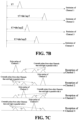
- the light emission mode of the lasers can include encoding emission time points of the four single pulses.
- Channel1 emits a single pulse at time point t1
- Channel2 emits a single pulse at time point t2
- Channel3 emits a single pulse at time point t3
- Channel4 emits a single pulse at time point t4
- the light emission time point is a time point corresponding to the time when the emitted pulse exceeds a particular preset threshold.
- the emission time point of Channel1 can be used as a reference time point to delay the other channels, which can also achieve the effect of encoding the emission time point.
- Channel1 emits a single pulse at time point t1
- Channel2 emits a single pulse at time point t1+delay1
- Channel3 emits a single pulse at time point t1+delay2
- Channel4 emits a single pulse at time point t1+delay3.
- Fig. 7C by encoding the emission time points, the delaying of echo pulses corresponding to the four channels to positions where they do not overlap with each other can be achieved to cause the echo pulse of a channel to be not interfered with by the echo pulses (which are the smaller pulses relative to the echo pulse of that channel shown in each channel in Fig. 7C ) of the other channels emitting light in parallel.
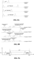
- At least part of the lasers are configured to emit multi-pulses to accomplish a single detection, the light emission mode thereof including: for the lasers emitting multi-pulses, emitting the first pulses in parallel and encoding an interval of the multi-pulses, that is, intervals between subsequent pulses and the first pulses.
- the light emission mode thereof including: for the lasers emitting multi-pulses, emitting the first pulses in parallel and encoding an interval of the multi-pulses, that is, intervals between subsequent pulses and the first pulses.
- channels Channel1, Channel2, Channel3, and Channel4 all emit double pulses.
- the time interval code1 between double pulses can be encoded, and for different emitting channels, different code1 can optionally be set. For example, with reference to Fig.
- Fig. 8A shows a schematic diagram of an echo pulse determined after encoding the time interval of the pulses using the approach of Fig. 8A .
- Fig. 8B shows a schematic diagram of an echo pulse determined after encoding the time interval of the pulses using the approach of Fig. 8A .
- Fig. 8B by encoding the time intervals of the multi-pulses, the delaying of ranging echo pulses corresponding to the four channels to positions where they do not overlap with each other (to avoid confusion, for each channel, instead of showing the double pulse, only the ranging echo pulse corresponding to the ranging pulse in the double pulse is shown, so that Fig. 8B superficially appears to be the same as Fig. 7c , but actually depicts a different application scenario) can be realized to cause the ranging echo pulse of a channel to be not interfered with by ranging echo pulses of the other channels that are received at the same time.
- Figs. 7A-8B do not show a case in which a part of the channels emitting light in parallel emits single pulses and a part emits multi-pulses, in practice, this scheme is also applicable to this disclosure.
- the encoding can be performed with reference to the approach of Fig. 7A or Fig. 7B
- the encoding can be performed with reference to the approach of Fig. 8A .
- the ranging echo pulse corresponding to the ranging pulse emitted by each of the channels emitting light in parallel can fall at different positions in the total ToF window as far as possible and are staggered from each other, the crosstalk caused by parallel light emission of multiple channels can be mitigated or eliminated.
- step S11 of determining the light emission mode of the lasers is briefly described, and the details of how to set the light emission mode and of the realized anti-interference effect are described later. The description proceeds below to step S12 in the control method 10.
- the channels are controlled to emit light in groups, lasers of channels within each group emitting light in parallel, where pulses emitted by the lasers of the group of channels are encoded in accordance with the light emission mode, at least one of pulses emitted by each laser serving as a ranging pulse.
- the ranging pulse is the pulse used to calculate the ToF.
- the 1st or 2nd pulse or both can be used as the ranging pulse for that channel.
- a part of the lasers can be configured to emit a single pulse and the single pulse serves as the ranging pulse for the channel.
- the emission of multi-pulses can prevent crosstalk, either crosstalk between the channels of the current LiDAR, or crosstalk from other LiDARs that are present in the current region at the same time.
- each pulse in the multi-pulse can be used for ranging or be selected as a ranging pulse.
- a non-first pulse of multiple pulses can be chosen as the ranging pulse.
- whether the echo of the 1st pulse is crosstalked (by so-called crosstalk, it is meant that for a channel in the channels emitting light in parallel, it is not possible to distinguish between a ranging echo pulse not belonging to this channel and a ranging echo pulse of this channel among the received ranging echo pulses) depends on the distance from the object (which is relatively difficult to change), while whether the subsequent pulse is crosstalked depends on the distance from the object (which is difficult to change) + the pulse interval code (which is relatively a value that can be changed).
- the non-first pulse is preferably chosen as the ranging pulse; or multiple pulses can be chosen as the ranging pulses. For example, in the case where a double pulse is emitted, with reference to Fig.
- the ranging result calculated by choosing the 2nd pulse as the ranging pulse is relatively accurate, and the measured distance d of the object is related to the position of the 2nd pulse-codel.
- the 3rd pulse is chosen as the ranging pulse and the measured distance d of the object is related to the position of the third pulse-code2-code1.
- the distance d is in the unit of length and the code is in the unit of time, both of which can be converted to the same unit. Therefore, for ease of description, the formula is only used to indicate the relationship between the two, and no conversion of measurement units has been performed.
- the light emission mode in the method 10 is configured to cause: ranging echo pulses of at least part of channels emitting light in parallel to be temporally staggered from each other.
- Fig. 10 shows a schematic diagram of a situation in which ranging echo pulses are staggered from each other in the case of parallel emission by 4 channels in an embodiment of this disclosure
- each group of emitting channels includes a total of four channels, Channel1, Channel2, Channel3, and Channel4 (it should be noted that, although numbered in the order of 1, 2, 3, and 4, these 4 channels that are actually emitting light in parallel typically have a relatively large physical spacing, and are not neighboring channels), and the four channels emit light in parallel, each of the channels emitting a number of pulses, one of which is chosen as the ranging pulse.
- Channel1 in addition to receiving the ranging echo pulse generated after the ranging pulse of this channel meets an external object, it can also receive echoes generated after the pulses emitted from other channels are reflected by the object (for these other channels, the echoes are ranging echo pulses if they are received by the channels themselves), which makes it impossible for this channel to distinguish between its own ranging echo pulse and the echoes of other channels, thus causing particular interference to the detection of this channel.
- the ranging echo pulses of the channels are temporally staggered from each other (non-ranging echo pulses are not shown, so the emitting end can emit single pulses or multi-pulses in the embodiment shown in Fig. 10 ).
- the ranging echo pulse of channel1 falls at a relatively front position in the total ToF window
- the ranging echo pulse of channel2 falls at a relatively back position in the total ToF window
- the ranging echo pulses of channel3 and channel4 fall at relatively middle positions in the total ToF window.
- Fig. 10 shows the situation of reception by channel1 and channel4 only. The situation of the echo pulses received by the other channels is similar and is not repeated here.
- control method 10 is preliminarily described by steps S11 and S12.
- the ToF required for the detection to be carried out can be predetermined on the basis of the previous ranging results, and the light emission mode corresponding to the lasers that are to perform emission can then be set. In the following, this is illustrated by way of an embodiment.
- the step S11 includes: predicting, based on previous ranging results of each channel, time of a ranging echo pulse corresponding to a ranging pulse to be emitted this time, and setting the light emission mode of lasers that are to perform detection.
- the single pulse is a ranging pulse.
- the laser first emits a single pulse at the T1 time point to determine a ranging result, and then predicts a ranging result that would have been determined if the detection were performed at the T2 time point. This prediction can be performed based on the type of the obstacle, the speed and direction of movement of the obstacle relative to the LiDAR, and the rotation speed or scanning frequency of the LiDAR (an interval between the T1 and T2 time points can be determined correspondingly).
- the process is performed separately for multiple channels emitting light in parallel to predict the ranging result for the next time point.
- the light emission mode of the lasers of the multiple channels at the T2 time point is set based on the predicted ranging results to cause the ranging echo pulses of the multiple channels emitting light in parallel to be staggered from each other.
- the emission time points of the single pulses of the lasers of each channel at the time point T2 are encoded to cause the echo pulses corresponding to the single pulses emitted at the time point T2 to be staggered from each other.
- the 2nd pulse is a ranging pulse
- a double pulse is first emitted in parallel at the T1 time point, and the ranging result is determined based on the ranging pulse; then the ranging result of a double pulse emitted at the T2 time point is predicted. The process is performed separately for multiple channels emitting light in parallel to predict the ranging result for the next time point.
- the light emission mode of the lasers of the multiple channels at the T2 time point are set based on the predicted ranging results. For example, the intervals of the double pulses of the lasers of each channel at the time point T2 are encoded to cause the double pulses emitted at the time point T2 and the received ranging echo pulses to be staggered from each other.
- the 1st pulses from the lasers of the multiple channels can be set to be emitted in parallel, to cause the ranging echo pulses can be staggered from each other by setting corresponding pulse interval times for each channel.
- the step S11 includes: predicting, based on previous ranging results of each channel and a channel neighboring the channel as well as obstacle information, time of a ranging echo pulse corresponding to a ranging pulse to be emitted, and setting the light emission mode of lasers that are to perform detection.
- the ranging result of that channel at the T2 time point is predicted, and based on the prediction result, the light emission mode of the lasers that are to perform emission is set.
- the distance detected by each channel at 2 neighboring horizontal angles ⁇ i and ⁇ i+1 is predicted, and the light emission mode of the lasers that are to perform emission is set based on the prediction result.
- a prediction result of a ranging pulse to be emitted is predicted, and based on the prediction result, a light emission mode of the lasers that are to perform emission is set.
- the purpose of using any one or more of the ways to set the light emission mode of the lasers that are to perform detection is all to enable the ranging pulses of at least some of the channels emitting light in parallel to be staggered from each other, and preferably the ranging pulses of each of the channels emitting light in parallel are staggered from each other.
- the criterion is that the processor can later distinguish between ranging echo pulses from its own channel and interfering pulses, to cause the ranging precision of that channel to be not affected.
- the embodiments all chose to use one pulse as the ranging echo pulse as an example.
- each channel emits multi-pulses
- at least two pulses can be chosen as ranging pulses from multiple pulses and the ranging result can be acquired based on the at least two ranging pulses, which can reduce the influence of signal crosstalk and improve the accuracy of the ranging result.
- multiple distances can be calculated based on the multiple ranging pulses and corresponding multiple ranging echo pulses, respectively, and then the multiple distances can be subjected to a weighted calculation based on preset weights of the multiple ranging pulses to arrive at a ranging result, which can reduce the effect of crosstalk on the ranging and improve the accuracy of the ranging. For example, if 4 pulses are emitted, with reference to Fig.
- the contribution of each pulse to the final ranging result d is given the same weight of 1. It can also be considered based on different weights. For example, a different weight Xi is assigned to each pulse, 1>Xi>0.
- the foregoing illustrates, by way of embodiments, how the accuracy of the ranging result can be improved.
- the total ToF window can be divided into intervals in advance, and then an interval that has not yet been marked and not yet been occupied can be assigned to each ranging echo pulse.
- this allows for a more precise control of the positions of the ranging echo pulses, which is further described below by means of preferred embodiments.
- the step S11 includes the following sub-steps:
- a total ToF window of lasers of multiple channels of each group is divided into at least a first interval and a second interval.
- the total ToF window is divided into two intervals, where a first interval is used for placing other pulses in front of the ranging echo pulses, and a second interval is used for placing the ranging echo pulses of the various channels.
- time of at least part of ranging echo pulses generated separately by ranging pulses to be emitted by the lasers of the multiple channels of the each group is predicted. Based on the previous ranging results of each channel or its neighboring channels, the time of the ranging echo pulse corresponding to the ranging pulse to be emitted is predicted.
- the light emission mode of lasers that are to perform detection is set to cause ranging echo pulses generated to be distributed in a non-overlapping manner (the degree of non-overlapping can be different for each LiDAR after lasers of at least part of multiple channels emitting light in parallel emit ranging pulses, , and the criterion is that the processor can later differentiate between the ranging echo pulses of this channel and the crosstalk pulses, to cause the ranging accuracy of this channel to be not affected) in the second interval.
- the light emission mode of the lasers is set based on the predicted time of the ranging echo pulses, to cause the ranging echo pulses to be distributed in a non-overlapping manner in the second interval by means of encoding of at least one of the emission time points the pulse intervals.
- Non-overlapping of ranging echo pulses includes the ranging echo pulses being temporally staggered from each other, separated from each other, not overlapping, spaced apart, falling at different positions, or the like.
- the sub-step Sill further includes: dividing the second interval into k sub-intervals, where k is an integer and is greater than or equal to the number of channels in the group to have each channel fall in a different sub-interval as much as possible.
- the sub-step S113 includes: setting the light emission mode of lasers that are to perform detection, to cause ranging echo pulses generated to be distributed in a non-overlapping manner in the k sub-intervals after lasers of at least part of multiple channels emitting light in parallel emit ranging pulses,.
- the total ToF window is divided into k+1 sub-intervals, G0, G1, G2, ..., and Gk, where G0 is equivalent to the first interval for placing the other pulses preceding the first received ranging echo pulses; and G1-Gk are used for placing the ranging echo pulses, where G1 is equivalent to the 1st sub-interval that theoretically exists for placing ranging echo pulses, and ideally, the non-ranging pulses preceding the first received ranging echo pulse are all concentrated within G0 and do not appear within G1-Gk.
- the length of each of the sub-intervals is greater than a maximum pulse width of ranging echo pulses of the LiDAR.
- the length of each interval is assumed to be G, with G being greater than the maximum pulse width of the ranging echo pulse to ensure that one ranging echo pulse can be placed in each sub-interval.
- G ⁇ 2 times the pulse width.
- each model of LiDAR can have a different pulse width.
- the maximum pulse width is about 30 ns, G is preferably 60 ns or more.
- the principle of dividing the length of the first interval is that other pulses preceding the ranging echo pulses can be placed at the smallest ranging distance.
- the length of the time window for G0 is (Wtof - k*G) and G 1 is the 1st sub-interval theoretically available for placing ranging echo pulses, so it is desirable as much as possible to have non-ranging echo pulses concentrated within GO and not in sub-intervals G1-Gk, thus enabling sub-intervals G1-Gk to be used for placing ranging echo pulses of the various channels.
- the length of the G0 interval is preferably chosen such that the 1st echo pulse and the 2nd echo pulse can be placed at the smallest ranging distance, and then G0 ⁇ dmin+code1+code2 can be set, where dmin is the smallest distance measurable by the LiDAR.
- the interval of G1 is approximately [dmin+code1+code2, dmin+code1+code2+G], and thus G1 corresponds to a theoretical 1st sub-interval used to place a ranging echo pulse (in this embodiment, the echo pulse of the 3rd pulse).
- the light emission mode can further be configured to cause at least part of ranging echo pulses generated by ranging pulses emitted by lasers of each channel to not overlap with non-ranging echo pulses generated by non-ranging pulses emitted by lasers of the other channels in the group.
- the step S113 includes: setting the light emission mode of lasers that are to perform detection to cause ranging echo pulses generated to be distributed in sub-intervals of the k sub-intervals that are unoccupied and closest in distance after lasers of at least part of the multiple channels emitting light in parallel emit ranging pulses.
- the ranging echo pulses By placing the ranging echo pulses in the unoccupied sub-intervals, the influence of crosstalk on the ranging results can be prevented. Further, by placing the ranging echo pulses in sub-intervals that are as close as possible, the measurement duration is shortened and the efficiency of the measurement is increased.
- the method of distributing ranging echo pulses of this preferred embodiment is specifically described below by means of Embodiments I through IV.
- a group of 4 channels (Channel 1, Channel 2, Channel 3, and Channel 4) of lasers emit light in parallel, where the lasers of each channel emit 3 pulses of which the 3rd pulse is a ranging pulse.
- the total ToF window is divided into sub-intervals G0, and G1-Gk, where the midpoint positions of the G1-Gk sub-intervals are g1-gk.
- each channel emits 3 pulses, where the time interval between the 1st pulse and the 2nd pulse is code1 and the time interval between the 2nd pulse and the 3rd pulse is code2.
- code1 is set to a fixed value, but those skilled in the art can understand that code1 can also be set to a different value to prevent crosstalk from other LiDARs, which means that the pulse intervals can be encoded;
- the minimum value of the pulse intervals code1 and code2 is defined as Cmin, where Cmin is related to the processing speed of the laser charging circuit of the emitting channel.
- Cmin ⁇ pulse width/2 can be set to more accurately distinguish 2 neighboring pulses.
- the previous ranging results are first determined based on the control method 10.
- the 4 channels Channel 1, Channel 2, Channel 3, and Channel 4 emit light in parallel, and the ranging results at an angle ⁇ i in the horizontal direction (or T1 time point, which corresponds to the description in the embodiments) are d1, d2, d3 and d4, respectively.
- the positions (time points) of the ranging echo pulses of the 4 channels Channel 1, Channel 2, Channel 3, and Channel 4 at an angle of ⁇ i+1 are predicted based on the previous ranging results, and the light emission mode is set based on the predicted positions of the ranging echo pulses, that is, the code2 of the light emitting pulses at the angle of ⁇ i+1 is encoded. Specifically, the following steps are performed prior to light emission:
- the lasers of the 4 channels are controlled to emit light based on the corresponding light emission mode.
- the ranging echo pulses generated by the 4 channels that synchronously emit light are temporally staggered from each other, thereby mitigating or avoiding the problem of crosstalk. It should be noted that only ranging echo pulses are shown at the receiving ends of the channels in Fig. 12 , while non-ranging echo pulses are not shown to avoid confusion.
- the ranging echo pulse of each channel is divided into the Gk interval to ensure that the point can be measured.
- the farther away the object is the weaker the crosstalk is (the obstacle is far away, so the echo for each channel is very weak, and the crosstalk to each other is also very weak), and the requirement of the accuracy of ranging at a distance is lower, so the ranging requirement can also be met.
- the pulse waveform thereof is as shown in Fig. 13 , where the crosstalk pulses (which, in terms of time points, roughly correspond to the time points of the ranging echo pulses of the other channels within the total flight window) fall between the second echo pulse and the third echo pulse, that is, between the non-ranging pulses (the first echo pulse and the second echo pulse) and the ranging echo pulse (the third echo pulse) of the channel, to cause the crosstalk pulses to be not interfere with the ranging of the channel, thereby determining accurate ranging results.
- the crosstalk pulses which, in terms of time points, roughly correspond to the time points of the ranging echo pulses of the other channels within the total flight window
- each channel emits double pulses of which the 2nd pulse is a ranging pulse.
- the total ToF window is divided into sub-intervals G0, and G1-Gk, where the midpoint positions of the G1-Gk sub-intervals are g1-gk.
- each channel emits double pulses, where the pulse interval is code1. Code1 should be greater than Cmin.
- the previous ranging results are first determined based on the control method 10. All channels emit light in parallel.
- the light emitting channels are Channel 1-Channel 16, and the ranging results at the angle ⁇ i in the horizontal direction are d1, d2, ..., d8, ..., and d16.
- the positions of the ranging echo pulses of the channels Channel 1-Channel 16 at the angle of ⁇ i+1 are predicted, and the light emission mode is set based on the predicted positions of the ranging echo pulses, that is, code1 of each of the channels is encoded, and finally the channels emit light in parallel at the angle of ⁇ i+1.
- the following steps are carried out:
- the ranging echo pulses generated by all the channels that synchronously emit light are temporally staggered from each other, thereby mitigating or avoiding the problem of crosstalk.
- the figure only illustrates the case where there are 16 channels emitting light in parallel, which are numbered sequentially as channels 1-16, but there is no limitation on exactly which of these channels correspond to which lines on the LiDAR, as it is related to the layout arrangement of multiple lasers of the LiDAR.
- the channels emitting light in parallel are multiple lines on a multi-line LiDAR that are physically spaced relatively far apart from each other in terms of their arrangement.
- the 31st line, the 60th line, the 70th line, and the 85th line may, for example, emit light in parallel.
- Embodiment III a group of 32 channels emit light in parallel, with each channel emitting 5 pulses, where the 5th pulse is a ranging pulse (it should be noted that with a greater number of channels emitting light in parallel, the probability and effect of crosstalk can be reduced by increasing the number of pulses emitted from a single detection of each channel).
- the total ToF window is divided into sub-intervals G0, and G1-Gk, where the midpoint positions of the G1-Gk sub-intervals are g1-gk.
- each channel emits 5 pulses, where the time interval between the 1st pulse and the 2nd pulse is code1, the time interval between the 2nd pulse and the 3rd pulse is code2, the time interval between the 3rd pulse and the 4th pulse is code3, and the time interval between the 4th pulse and the 5th pulse is code4.
- code1-code3 are set to fixed values, but those skilled in the art can understand that code1-code3 can also be set to different values to prevent crosstalk from other LiDARs. Among them, code1-code3 are all greater than Cmin.
- the previous ranging results are first determined based on the control method 10.
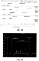
- the ranging echo pulses generated by all the 32 channels that synchronously emit light are temporally staggered from each other, thereby mitigating or avoiding the problem of crosstalk. It should be noted that only ranging echo pulses are shown at the receiving ends of the channels in Fig. 15 , while non-ranging echo pulses are not shown to avoid confusion.
- a group of 8 channels emit light in parallel, where each channel emits double pulses of which the 2nd pulse is a ranging pulse.
- the total ToF window is divided into sub-intervals G0, and G1-Gk, where the midpoint positions of the G1-Gk sub-intervals are g1-gk.
- each channel emits double pulses, where the pulse interval is code1 and code1 > Cmin.
- the ranging results at the horizontal angles that have already been detected previously are known, for example, the ranging results at the angle ⁇ i-1 in the horizontal direction, the ranging results at the angle ⁇ i-2 in the horizontal direction, ..., and based on these ranging results at the horizontal angles that have been detected previously, the ranging result at the angle ⁇ i+1 in the horizontal direction is predicted by combining object recognition as well as time intervals of neighboring detections, which can be dx.
- the positions of the ranging echo pulses of the channels Channel 1-Channel 8 at the angle of ⁇ i+1 are predicted, and the light emission mode is set based on the predicted positions of the ranging echo pulses, that is, code1 is encoded, and finally the channels emit light in parallel at the angle of ⁇ i+1.
- the specific steps are as follows:
- the ranging echo pulses generated by all the 16 channels that synchronously emit light are temporally staggered from each other, thereby mitigating or avoiding the problem of crosstalk. It should be noted that only ranging echo pulses are shown at the receiving ends of the channels in Fig. 16 , while non-ranging echo pulses are not shown to avoid confusion.
- the light emission mode of the emitting end is set based on the ranging results at the receiving end, and then the set light emission mode is used to control the emitting end to emit pulses, to cause the ranging echo pulse generated by the ranging pulse of each of the channels emitting light in parallel to fall in different intervals in the total ToF window Wtof and are thus staggered from each other, which reduces crosstalk between multiple channels emitting light in parallel of the same LiDAR and reduces crosstalk between different LiDARs to improve the accuracy of detection.
- This disclosure further relates to a computer storage medium including computer-executable instructions stored thereon, where the executable instructions, when executed by a processor, implement the control method 10 as described.
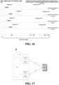
- This disclosure further relates to a multi-channel LiDAR 20, as shown in Fig. 17 , including:
- At least part of the lasers 21 are configured to emit single pulses, and the controller apparatus 23 is further configured to: encode, for the lasers 21 emitting the single pulses, emission time points of the single pulses.
- At least part of the lasers 21 are configured to emit multi-pulses, and the controller apparatus 23 is further configured to: for the lasers 21 emitting the multi-pulses, emit the first pulses in parallel and encode intervals of the multi-pulses.
- the controller apparatus 23 is configured to: predict, based on previous ranging results of each channel, time of a ranging echo pulse corresponding to a ranging pulse to be emitted, and set the light emission mode of the lasers 21 that are to emit light.
- the controller apparatus 23 is configured to: predict, based on previous ranging results of each channel and a channel neighboring the channel as well as obstacle information, time of a ranging echo pulse corresponding to a ranging pulse to be emitted, and set the light emission mode of lasers 21 that are to perform detection.
- the controller apparatus 23 is configured to determine the light emission mode by means of:
- controller apparatus 23 is configured to:
- the length of each of the sub-intervals is greater than a maximum pulse width of ranging echo pulses of the LiDAR 20.
- the controller apparatus 23 is configured to: set the light emission mode of lasers 21 that are to perform detection to cause ranging echo pulses generated to be distributed in sub-intervals of the k sub-intervals that are unoccupied and closest in distance after lasers 21 of at least part of the multiple channels emitting light in parallel emit ranging pulses.
- the light emission mode is configured to cause at least part of ranging echo pulses separately generated by ranging pulses emitted by lasers 21 of the group of channels to be temporally staggered from each other, and ranging echo pulses generated by ranging pulses emitted by lasers 21 of each channel to not overlap with non-ranging echo pulses generated by non-ranging pulses emitted by lasers 21 of the other channels in the group.
- the multiple pulses include at least two ranging pulses, where the ranging pulses are non-first pulses of the multiple pulses.
- the controller apparatus 23 is further configured to: calculate multiple distances based on multiple ranging pulses and corresponding multiple ranging echo pulses, respectively; and calculate, based on preset weights of the multiple ranging pulses, a ranging result in a weighted manner based on the multiple distances.
- the total ToF window is related to ToF corresponding to a maximum detection distance of the LiDAR 20 and an emission duration of the multi-pulses.
Landscapes
- Engineering & Computer Science (AREA)
- Physics & Mathematics (AREA)
- Computer Networks & Wireless Communication (AREA)
- General Physics & Mathematics (AREA)
- Radar, Positioning & Navigation (AREA)
- Remote Sensing (AREA)
- Electromagnetism (AREA)
- Optical Radar Systems And Details Thereof (AREA)
Applications Claiming Priority (2)
| Application Number | Priority Date | Filing Date | Title |
|---|---|---|---|
| CN202111550464.6A CN116265983A (zh) | 2021-12-17 | 2021-12-17 | 激光雷达的控制方法以及多通道激光雷达 |
| PCT/CN2022/098514 WO2023109042A1 (zh) | 2021-12-17 | 2022-06-14 | 激光雷达的控制方法以及多通道激光雷达 |
Publications (2)
| Publication Number | Publication Date |
|---|---|
| EP4451005A1 true EP4451005A1 (de) | 2024-10-23 |
| EP4451005A4 EP4451005A4 (de) | 2025-03-19 |
Family
ID=86743582
Family Applications (1)
| Application Number | Title | Priority Date | Filing Date |
|---|---|---|---|
| EP22905808.6A Pending EP4451005A4 (de) | 2021-12-17 | 2022-06-14 | Steuerungsverfahren für lidar und mehrkanal-lidar |
Country Status (4)
| Country | Link |
|---|---|
| US (1) | US20240337734A1 (de) |
| EP (1) | EP4451005A4 (de) |
| CN (1) | CN116265983A (de) |
| WO (1) | WO2023109042A1 (de) |
Families Citing this family (3)
| Publication number | Priority date | Publication date | Assignee | Title |
|---|---|---|---|---|
| CN119270285B (zh) * | 2023-07-07 | 2025-12-16 | 深圳市速腾聚创科技有限公司 | 雷达控制方法、装置、终端设备及计算机可读存储介质 |
| CN117075128B (zh) * | 2023-09-11 | 2024-04-09 | 深圳市速腾聚创科技有限公司 | 测距方法、装置、电子设备和计算机可读存储介质 |
| CN120630155B (zh) * | 2025-08-11 | 2026-01-06 | 深圳市速腾聚创科技有限公司 | 雷达控制方法、装置、终端设备及计算机程序产品 |
Family Cites Families (6)
| Publication number | Priority date | Publication date | Assignee | Title |
|---|---|---|---|---|
| CN104035097B (zh) * | 2014-07-01 | 2016-09-28 | 清华大学 | 一种阵列发射单元接收的无扫描三维激光探测装置及方法 |
| CN104931973B (zh) * | 2015-06-17 | 2017-05-10 | 浙江理工大学 | 用于激光雷达系统的非对称相位编码测距方法 |
| CN114942453A (zh) * | 2019-03-08 | 2022-08-26 | 欧司朗股份有限公司 | Lidar传感器系统、用于该系统的光学部件、传感器和方法 |
| CN112799032B (zh) * | 2019-11-13 | 2024-07-23 | 浙江舜宇智能光学技术有限公司 | 用于激光雷达的防通道间串扰的方法及其系统和电子设备 |
| CN113176555B (zh) * | 2020-01-24 | 2024-09-24 | 上海禾赛科技有限公司 | 激光雷达的发射单元、激光雷达以及测距方法 |
| CN112953645B (zh) * | 2021-01-27 | 2023-02-28 | 吉林大学 | 一种同时实现激光测距与通信的系统与方法 |
-
2021
- 2021-12-17 CN CN202111550464.6A patent/CN116265983A/zh active Pending
-
2022
- 2022-06-14 WO PCT/CN2022/098514 patent/WO2023109042A1/zh not_active Ceased
- 2022-06-14 EP EP22905808.6A patent/EP4451005A4/de active Pending
-
2024
- 2024-06-17 US US18/745,499 patent/US20240337734A1/en active Pending
Also Published As
| Publication number | Publication date |
|---|---|
| US20240337734A1 (en) | 2024-10-10 |
| WO2023109042A1 (zh) | 2023-06-22 |
| CN116265983A (zh) | 2023-06-20 |
| EP4451005A4 (de) | 2025-03-19 |
Similar Documents
| Publication | Publication Date | Title |
|---|---|---|
| EP4451005A1 (de) | Steuerungsverfahren für lidar und mehrkanal-lidar | |
| CN110749898B (zh) | 一种激光雷达测距系统及其测距方法 | |
| CN110780306B (zh) | 一种激光雷达抗干扰方法及激光雷达 | |
| CN114518568B (zh) | 激光雷达的控制方法及激光雷达 | |
| US20220120867A1 (en) | Transmitting unit of laser radar, laser radar, and distance measurement method | |
| US20160259058A1 (en) | Laser scanning apparatus and method | |
| US20220120897A1 (en) | Ranging method for lidar system, and lidar system | |
| CN114365007B (zh) | 测量到目标距离的方法 | |
| US11796649B2 (en) | Method and device for optically measuring distances | |
| US20240159880A1 (en) | Control method for laser radar, and laser radar | |
| CN109923437B (zh) | 激光雷达系统 | |
| CN115166760A (zh) | 激光雷达及测距方法 | |
| CN114646942B (zh) | 激光雷达的控制方法及激光雷达 | |
| KR20240004373A (ko) | 레이저 레이더 및 거리 측정 방법 | |
| KR101386640B1 (ko) | 레이저 레이더 시스템의 고스트 영상 제거 방법 | |
| US11506761B2 (en) | Method and device for optical distance measurement | |
| EP4506721A1 (de) | Laserradarsteuerungsverfahren, computerspeichermedium und laserradar | |
| CN111929662B (zh) | 感测装置 | |
| CN116953666A (zh) | 激光雷达及其探测方法、可读存储介质 | |
| CN115436962B (zh) | 激光雷达及获取特征信息的方法 | |
| CN112596066B (zh) | 激光雷达的测距方法、测距装置及存储介质 | |
| CN115932798A (zh) | 激光雷达收发器、激光雷达探测系统及探测方法 | |
| US20240183988A1 (en) | Method and apparatus for improving resolution of lidar, and lidar |
Legal Events
| Date | Code | Title | Description |
|---|---|---|---|
| STAA | Information on the status of an ep patent application or granted ep patent |
Free format text: STATUS: THE INTERNATIONAL PUBLICATION HAS BEEN MADE |
|
| PUAI | Public reference made under article 153(3) epc to a published international application that has entered the european phase |
Free format text: ORIGINAL CODE: 0009012 |
|
| STAA | Information on the status of an ep patent application or granted ep patent |
Free format text: STATUS: REQUEST FOR EXAMINATION WAS MADE |
|
| 17P | Request for examination filed |
Effective date: 20240716 |
|
| AK | Designated contracting states |
Kind code of ref document: A1 Designated state(s): AL AT BE BG CH CY CZ DE DK EE ES FI FR GB GR HR HU IE IS IT LI LT LU LV MC MK MT NL NO PL PT RO RS SE SI SK SM TR |
|
| P01 | Opt-out of the competence of the unified patent court (upc) registered |
Free format text: CASE NUMBER: APP_65042/2024 Effective date: 20241209 |
|
| A4 | Supplementary search report drawn up and despatched |
Effective date: 20250219 |
|
| RIC1 | Information provided on ipc code assigned before grant |
Ipc: G01S 7/486 20200101ALI20250213BHEP Ipc: G01S 7/481 20060101ALI20250213BHEP Ipc: G01S 17/931 20200101ALI20250213BHEP Ipc: G01S 17/87 20200101ALI20250213BHEP Ipc: G01S 17/42 20060101ALI20250213BHEP Ipc: G01S 7/4865 20200101ALI20250213BHEP Ipc: G01S 17/10 20200101ALI20250213BHEP Ipc: G01S 7/484 20060101AFI20250213BHEP |
|
| DAV | Request for validation of the european patent (deleted) | ||
| DAX | Request for extension of the european patent (deleted) |