EP4450869A1 - Lamp - Google Patents
Lamp Download PDFInfo
- Publication number
- EP4450869A1 EP4450869A1 EP22906429.0A EP22906429A EP4450869A1 EP 4450869 A1 EP4450869 A1 EP 4450869A1 EP 22906429 A EP22906429 A EP 22906429A EP 4450869 A1 EP4450869 A1 EP 4450869A1
- Authority
- EP
- European Patent Office
- Prior art keywords
- heat dissipation
- dissipation structure
- light source
- source assembly
- lamp body
- Prior art date
- Legal status (The legal status is an assumption and is not a legal conclusion. Google has not performed a legal analysis and makes no representation as to the accuracy of the status listed.)
- Pending
Links
- 230000017525 heat dissipation Effects 0.000 claims abstract description 95
- 230000013011 mating Effects 0.000 claims description 16
- 238000002844 melting Methods 0.000 claims description 6
- 230000008018 melting Effects 0.000 claims description 6
- 239000002184 metal Substances 0.000 claims description 3
- 230000002093 peripheral effect Effects 0.000 claims description 2
- 238000004904 shortening Methods 0.000 abstract description 2
- 238000000034 method Methods 0.000 description 6
- 239000000243 solution Substances 0.000 description 6
- 239000011324 bead Substances 0.000 description 4
- 238000010586 diagram Methods 0.000 description 4
- 238000004026 adhesive bonding Methods 0.000 description 1
- 230000009286 beneficial effect Effects 0.000 description 1
- 238000009792 diffusion process Methods 0.000 description 1
- 238000001746 injection moulding Methods 0.000 description 1
- 238000002955 isolation Methods 0.000 description 1
- 239000000463 material Substances 0.000 description 1
- 238000000465 moulding Methods 0.000 description 1
- 238000003466 welding Methods 0.000 description 1
Images



Classifications
-
- F—MECHANICAL ENGINEERING; LIGHTING; HEATING; WEAPONS; BLASTING
- F21—LIGHTING
- F21V—FUNCTIONAL FEATURES OR DETAILS OF LIGHTING DEVICES OR SYSTEMS THEREOF; STRUCTURAL COMBINATIONS OF LIGHTING DEVICES WITH OTHER ARTICLES, NOT OTHERWISE PROVIDED FOR
- F21V29/00—Protecting lighting devices from thermal damage; Cooling or heating arrangements specially adapted for lighting devices or systems
- F21V29/50—Cooling arrangements
- F21V29/502—Cooling arrangements characterised by the adaptation for cooling of specific components
- F21V29/503—Cooling arrangements characterised by the adaptation for cooling of specific components of light sources
-
- F—MECHANICAL ENGINEERING; LIGHTING; HEATING; WEAPONS; BLASTING
- F21—LIGHTING
- F21V—FUNCTIONAL FEATURES OR DETAILS OF LIGHTING DEVICES OR SYSTEMS THEREOF; STRUCTURAL COMBINATIONS OF LIGHTING DEVICES WITH OTHER ARTICLES, NOT OTHERWISE PROVIDED FOR
- F21V19/00—Fastening of light sources or lamp holders
-
- F—MECHANICAL ENGINEERING; LIGHTING; HEATING; WEAPONS; BLASTING
- F21—LIGHTING
- F21V—FUNCTIONAL FEATURES OR DETAILS OF LIGHTING DEVICES OR SYSTEMS THEREOF; STRUCTURAL COMBINATIONS OF LIGHTING DEVICES WITH OTHER ARTICLES, NOT OTHERWISE PROVIDED FOR
- F21V29/00—Protecting lighting devices from thermal damage; Cooling or heating arrangements specially adapted for lighting devices or systems
-
- F—MECHANICAL ENGINEERING; LIGHTING; HEATING; WEAPONS; BLASTING
- F21—LIGHTING
- F21V—FUNCTIONAL FEATURES OR DETAILS OF LIGHTING DEVICES OR SYSTEMS THEREOF; STRUCTURAL COMBINATIONS OF LIGHTING DEVICES WITH OTHER ARTICLES, NOT OTHERWISE PROVIDED FOR
- F21V29/00—Protecting lighting devices from thermal damage; Cooling or heating arrangements specially adapted for lighting devices or systems
- F21V29/50—Cooling arrangements
- F21V29/70—Cooling arrangements characterised by passive heat-dissipating elements, e.g. heat-sinks
-
- F—MECHANICAL ENGINEERING; LIGHTING; HEATING; WEAPONS; BLASTING
- F21—LIGHTING
- F21V—FUNCTIONAL FEATURES OR DETAILS OF LIGHTING DEVICES OR SYSTEMS THEREOF; STRUCTURAL COMBINATIONS OF LIGHTING DEVICES WITH OTHER ARTICLES, NOT OTHERWISE PROVIDED FOR
- F21V17/00—Fastening of component parts of lighting devices, e.g. shades, globes, refractors, reflectors, filters, screens, grids or protective cages
- F21V17/06—Fastening of component parts of lighting devices, e.g. shades, globes, refractors, reflectors, filters, screens, grids or protective cages the fastening being onto or by the lampholder
-
- F—MECHANICAL ENGINEERING; LIGHTING; HEATING; WEAPONS; BLASTING
- F21—LIGHTING
- F21V—FUNCTIONAL FEATURES OR DETAILS OF LIGHTING DEVICES OR SYSTEMS THEREOF; STRUCTURAL COMBINATIONS OF LIGHTING DEVICES WITH OTHER ARTICLES, NOT OTHERWISE PROVIDED FOR
- F21V17/00—Fastening of component parts of lighting devices, e.g. shades, globes, refractors, reflectors, filters, screens, grids or protective cages
- F21V17/10—Fastening of component parts of lighting devices, e.g. shades, globes, refractors, reflectors, filters, screens, grids or protective cages characterised by specific fastening means or way of fastening
- F21V17/12—Fastening of component parts of lighting devices, e.g. shades, globes, refractors, reflectors, filters, screens, grids or protective cages characterised by specific fastening means or way of fastening by screwing
-
- F—MECHANICAL ENGINEERING; LIGHTING; HEATING; WEAPONS; BLASTING
- F21—LIGHTING
- F21Y—INDEXING SCHEME ASSOCIATED WITH SUBCLASSES F21K, F21L, F21S and F21V, RELATING TO THE FORM OR THE KIND OF THE LIGHT SOURCES OR OF THE COLOUR OF THE LIGHT EMITTED
- F21Y2115/00—Light-generating elements of semiconductor light sources
- F21Y2115/10—Light-emitting diodes [LED]
Definitions
- the present application relates to a lamp, belonging to the technical field of lighting.
- the design for heat dissipation of lamps is generally realized by reducing a heat conduction path or reducing a thermal resistance, which is often implemented by filling a thermally conductive plastic part.
- a size of the plastic part an injection molding process thereof will cause a deformation, thus increasing the heat conduction path.
- the plastic part due to the pursuit of cost saving, the plastic part usually is made of a modified PP material and would be seriously deformed after molding, which results in poor heat dissipation rate of the whole lamp.
- the objective of the present disclosure is to provide a lamp so as to improve the heat dissipation rate of the whole lamp.
- the present disclosure provides a lamp including a lamp body and a light source assembly arranged in the lamp body, wherein the lamp further includes a heat dissipation structure and a fastener which are located between the lamp body and the light source assembly; the lamp body is provided with at least one perforation, and one side of the heat dissipation structure facing towards the lamp body is provided with a blind hole corresponding to the perforation; the fastener is configured to pass through the perforation to be connected with the blind hole so as to reduce a gap between the heat dissipation structure and the lamp body; one side of the heat dissipation structure facing towards the light source assembly is provided with a connecting part, and the connecting part is connected with the light source assembly to reduce a gap between the light source assembly and the heat dissipation structure.
- the heat dissipation structure is provided with a protrusion protruding towards the light source assembly, the blind hole is arranged in the protrusion, and the light source assembly is provided with a through hole corresponding to the protrusion, wherein the protrusion is inserted into the through hole to limit a connection between the light source assembly and the heat dissipation structure.
- the light source assembly is further provided with a connecting hole corresponding to the connecting part, and the connecting part is tightly fitted with the connecting hole.
- the light source assembly is further provided with a connecting hole corresponding to the connecting part, and the connecting part passes through the connecting hole to be connected with the light source assembly by means of hot melting.
- the lamp body includes a first shell and a second shell surrounding the first shell; the perforation is formed at a top of the first shell and penetrates through the first shell; an accommodating chamber is formed inside the first shell, and the heat dissipation structure is accommodated in the accommodating chamber and is attached to the top of the first shell.
- the heat dissipation structure includes a first connecting plate and a second connecting plate surrounding the first connecting plate, and both the connecting part and the blind hole are arranged on the first connecting plate ; an outer side wall of the second connecting plate is provided with a positioning part, an inner side wall of the first shell is correspondingly provided with a mating part, and the positioning part and the mating part are fitted with each other so that the heat dissipation structure is accommodated and fixed in the accommodating cavity .
- the first shell includes a top plate and an annular side plate connected with an edge of a periphery of the top plate; one end of the annular side plate away from the top plate is connected with the second shell, the perforation is arranged on the top plate, the first connecting plate of the heat dissipation structure is attached to the top plate, and the second connecting plate of the heat dissipation structure is attached to the annular side plate.
- the positioning part is a hook arranged on the second connecting plate
- the mating part is a protrusion rib arranged on the inner side wall of the first shell.
- the heat dissipation structure and the lamp body are both in a circular shape
- the mating part is an annular protrusion rib arranged on the inner side wall of the first shell, and a plurality of hooks are arranged and evenly distributed on the outer side wall of the second connecting plate.
- the fastener is a screw
- the perforation is a screw hole
- the heat dissipation structure is an insulating plastic part
- the lamp body is a metal lamp body.
- the lamp body is provided with a perforation while the heat dissipation structure is provided with a blind hole corresponding to the perforation, so that the fastener can pass through the perforation to be connected with the blind hole; in this way, the heat dissipation structure can be stretched for flattening, and meanwhile the heat dissipation path between the heat dissipation structure and each of the lamp body and the light source assembly can be shortened, thereby improving the heat dissipation rate of the whole lamp.
- lamp 100 lamp body 10; perforation 11; first shell 12; top plate 121; annular side plate 122; second shell 13; accommodating cavity 14; mating part 15; lead hole 16; connecting part 17; heat dissipation structure 20; blind hole 21; connecting part 22; protrusion 23; first connecting plate 24; second connecting plate 25; cavity 26; positioning part 27; opening 28; light source assembly 30; through hole 31; connecting hole 32; light source plate 33; lamp bead 34; notch 35; light-transmitting cover 40; fasteners 50.
- a lamp 100 which includes a lamp body 10, a heat dissipation structure 20, a light source assembly 30, a light-transmitting cover 40 and a fastener 50 for connecting the lamp body 10 and the heat dissipation structure 20.
- the light source assembly 30, the heat dissipation structure 20 and the lamp body 10 are assembled in sequence, and the light-transmitting cover 40 is assembled finally.
- the lamp body 10 is provided with at least one perforation 11; one side of the heat dissipation structure 20 facing towards the lamp body 10 is provided with a blind hole 21 corresponding to the perforation 11; and the fastener 50 passes through the perforation 11 to be connected with the blind hole 21, so as to fixedly connect the lamp body 10 and the heat dissipation structure 20 and to reduce a gap between the heat dissipation structure 20 and the lamp body 10.
- the lamp body 10 includes a first shell 12 and a second shell 13 surrounding an outer side of the first shell 12; a perforation 11 is formed at the top of the first shell 12 and penetrates through the first shell 12.
- An accommodating cavity 14 is formed inside the first shell 12, and the heat dissipation structure 20 is accommodated in the accommodating cavity 14 and attached to the top of the first shell 12.
- the first shell 12 includes a top plate 121 and an annular side plate 122 connected with a peripheral edge of the top plate 121; one end of the annular side plate 122 away from the top plate 121 extends in a circumferential direction and is connected with the second shell 13.
- the lamp body 10 can be formed as a double-shell structure, so that the second shell 13 can be used to shield a connection structure between the lamp body 10 and the heat dissipation structure 20, which enables the whole lamp 100 to be more artistic.
- the lamp 100 is a downlight, and both the first shell 12 and the second shell 13 are in a cylindrical shape, but the present disclosure is not limited thereto.
- the perforation 11 is formed in the top plate 121, and the fastener 50 directly passes through the top plate 121 until it is connected with the blind hole 21, so that the lamp body 10 and the heat dissipation structure 20 can be fixedly connected.
- the light-transmitting cover 40 is further accommodated in the accommodating cavity 14. Specifically, a connecting part 17 for fixing the light-transmitting cover 40 is arranged at the bottom of the first shell 12, close to a joint between the first shell 12 and the second shell 13.
- the connecting part 17 is arranged in an annular shape and is arranged on an inner side wall of the first shell 12 to be snap-fitted with the light-transmitting cover 40, so that the light-transmitting cover 40 is fixedly accommodated in the accommodating cavity 14, which can not only ensure a full diffusion of light, but also protect the light-transmitting cover 40 from being damaged.
- the specific type of the light-transmitting cover 40, as well as the specific assembling mode between the light-transmitting cover 40 and the lamp body 10 are not limited in the present disclosure, and the existing assembling solution can be adopted or adjusted adaptively according to actual situations.
- the heat dissipation structure 20 includes a first connecting plate 24 and a second connecting plate 25 surrounding the first connecting plate 24.
- the first connecting plate 24 is in a circular shape
- the second connecting plate 25 is in an annular shape, so as to form a cavity 26 for accommodating the light source assembly 30 between the first connecting plate 24 and the second connecting plate 25.
- the first connecting plate 24 of the heat dissipation structure 20 is attached to the top plate 121 of the first shell 12; and the second connecting plate 25 is attached to the annular side plate 122.
- the blind hole 21 is arranged on the first connecting plate 24; preferably, the first connecting plate 24 is provided with a protrusion 23 protruding towards the light source assembly 30; and the blind hole 21 is arranged in the protrusion 23.
- the blind hole can be directly formed in the first connecting plate 24 and the protrusion may be not provided, which is not limited in the present disclosure.
- the fastener 50 is preferably a screw
- the perforation 11 is preferably a screw hole
- an inner wall surface of the blind hole 21 is also provided with a screw thread correspondingly; in this way, the screw can pass through the screw hole and be locked and fixed in the blind hole 21, so that the heat dissipation structure 20 can be stretched for flattening and the first connecting plate 24 of the heat dissipation structure 20 can be closely attached onto the top plate 121 of the lamp body 10, thereby reducing the gap between the heat dissipation structure 20 and the lamp body 10, and hence shortening the heat conduction path between the heat dissipation structure 20 and the lamp body 10.
- the light source assembly 30 is provided with a through hole 31 corresponding to the protrusion 23, and the protrusion 23 is inserted into the through hole 31.
- the light source assembly 30 includes a light source plate 33 and a lamp bead 34 fixed on the light source plate 33.
- the through hole 31 is arranged on the light source plate 33, and the protrusion 23 is inserted into the through hole 31, which not only can limit the connection between the light source assembly 30 and the heat dissipation structure 20, but also can make the whole lamp 100 thinner and lighter.
- the heat dissipation structure 20 is further provided with a connecting part 22 protruding towards the light source assembly 30, and the connecting part 22 is in direct contact with the light source assembly 30, so as to further reduce the connection gap between the light source assembly 30 and the heat dissipation structure 20, that is, the heat dissipation path.
- the connecting part 22 is arranged on the first connecting plate 24, and the light source plate 33 is provided with a connecting hole 32 corresponding to the connecting part 22, and the connecting part 22 is tightly fitted with the connecting hole 32.
- the connecting part 22 passes through the connecting hole 32 to be connected with the light source assembly 30 by hot melting.
- the light source assembly 30 can be in direct contact with the heat dissipation structure 20, and on the other hand, the light source assembly 30 and the heat dissipation structure 20 can be restricted from moving randomly, so that the connection between the light source assembly 30 and the heat dissipation structure 20 has better stability.
- the connecting part 22 is a limiting post, and the limiting post 22 is connected with the light source assembly 30 by hot melting.
- the connection between the connecting part 22 and the light source assembly 30 is not limited to be connected by hot melting, but can also be connected by ultrasonic welding, gluing, etc., as long as the connecting part 22 and the light source assembly 30 can be connected with each other, which is not particularly limited here.
- An outer side wall of the second connecting plate 25 is provided with a positioning part 27, and an inner side wall of the first shell 12 is correspondingly provided with a mating part 15.
- the positioning part 27 and the mating part 15 are fitted with each other so that the heat dissipation structure 20 is accommodated and fixed in the accommodating cavity 14.
- the positioning portion 27 is a hook provided on the second connecting plate 25, and the mating part 15 is a protrusion rib provided on the inner side wall of the first shell 12.
- the heat dissipation structure 20 and the lamp body 10 are preferably in a circular shape.
- the mating part 15 is an annular protrusion rib arranged on the inner side wall of the first shell 12, and a plurality of hooks are arranged and evenly distributed on the outer side wall of the second connecting plate 25.
- the positioning part 27 and the mating part 15 can also have other structures, as long as the heat dissipation structure 20 can be accommodated and fixed in the accommodating cavity 14, which is not particularly limited here. With the arrangement of the positioning part 27 and the mating part 15, the lamp body 10 and the heat dissipation structure 20 can be fixed in advance, so that they can be fixedly connected again by using the fasteners 50 later.
- the lamp body 10 is further provided with a lead hole 16 for wiring connection, and the heat dissipation structure 20 is further provided with a columnar-shaped opening 28 corresponding to the lead hole 16.
- a notch 35 is provided at the edge of the light source plate 33. The wirings sequentially pass through the lead hole 16 and the opening 28, and are pressed into the notch 35, so as to be electrically connected with the light source assembly 30.
- the lamp body 10 is preferably a metal lamp body 10 having thermal conductivity property
- the heat dissipation structure 20 is preferably an insulating plastic part. Firstly, the light source assembly 30 is placed into the cavity 26 of the heat dissipation structure 20; and the protrusion 23 and the connecting part 22 on the heat dissipation structure 20 are inserted into the through hole 31 and the connecting hole 32 on the light source plate 33, respectively; and then the connecting part 22 is fixedly connected with the light source plate 33 by hot melting.
- the heat dissipation structure 20 assembled with the light source assembly 30 is placed in the accommodating cavity 14 of the lamp body 10, and the positioning part 27 on the heat dissipation structure 20 is fixedly connected with the mating part 15 on the lamp body 10, so that the heat dissipation structure 20 and the lamp body 10 are snap-fitted with each other and positioned.
- the fastener 50 is inserted through the perforation 11 in the lamp body 10 until it is connected with the blind hole 21, so that the fastener 50 is fixedly locked to lock and fix the heat dissipation structure 20 and the lamp body 10.
- the light-transmitting cover 40 and the lamp body 10 are assembled and fixed, and the assembling process of the lamp 100 is completed.
- the heat dissipation path of the whole lamp 100 is as follows: the heat is transmitted from the lamp bead 34 to the light source plate 33, then from the light source plate 33 to the heat dissipation structure 20, then from the heat dissipation structure 20 to the lamp body 10, and finally the lamp body 10 transmits the heat out of the lamp 100.
- the heat dissipation efficiency of the whole lamp 100 is improved.
- the lamp body 10 is provided with a perforation 11 while the heat dissipation structure 20 is provided with a blind hole 21 corresponding to the perforation 11, so that the fastener 50 can pass through the perforation 11 to be connected with the blind hole 21; in this way, the heat dissipation structure 20 can be stretched for flattening, so as to shorten the heat dissipation path between the heat dissipation structure 20 and each of the lamp body 10 and the light source assembly 30, thereby improving the heat dissipation rate of the whole lamp, and prolonging the service life of the lamp 100.
Landscapes
- Engineering & Computer Science (AREA)
- General Engineering & Computer Science (AREA)
- Non-Portable Lighting Devices Or Systems Thereof (AREA)
- Arrangement Of Elements, Cooling, Sealing, Or The Like Of Lighting Devices (AREA)
Abstract
Description
- The present application claims the priority of
Chinese patent application with the application number of 202123130705.X - The present application relates to a lamp, belonging to the technical field of lighting.
- In the prior art, the design for heat dissipation of lamps is generally realized by reducing a heat conduction path or reducing a thermal resistance, which is often implemented by filling a thermally conductive plastic part. However, with the increase of a size of the plastic part, an injection molding process thereof will cause a deformation, thus increasing the heat conduction path. Especially, due to the pursuit of cost saving, the plastic part usually is made of a modified PP material and would be seriously deformed after molding, which results in poor heat dissipation rate of the whole lamp.
- In view of this, it is necessary to improve the existing lamps to solve the above problems.
- The objective of the present disclosure is to provide a lamp so as to improve the heat dissipation rate of the whole lamp.
- In order to achieve the above objective, the present disclosure provides a lamp including a lamp body and a light source assembly arranged in the lamp body, wherein the lamp further includes a heat dissipation structure and a fastener which are located between the lamp body and the light source assembly; the lamp body is provided with at least one perforation, and one side of the heat dissipation structure facing towards the lamp body is provided with a blind hole corresponding to the perforation; the fastener is configured to pass through the perforation to be connected with the blind hole so as to reduce a gap between the heat dissipation structure and the lamp body; one side of the heat dissipation structure facing towards the light source assembly is provided with a connecting part, and the connecting part is connected with the light source assembly to reduce a gap between the light source assembly and the heat dissipation structure.
- As a further improvement of the present disclosure, the heat dissipation structure is provided with a protrusion protruding towards the light source assembly, the blind hole is arranged in the protrusion, and the light source assembly is provided with a through hole corresponding to the protrusion, wherein the protrusion is inserted into the through hole to limit a connection between the light source assembly and the heat dissipation structure.
- As a further improvement of the present disclosure, the light source assembly is further provided with a connecting hole corresponding to the connecting part, and the connecting part is tightly fitted with the connecting hole.
- As a further improvement of the present disclosure, the light source assembly is further provided with a connecting hole corresponding to the connecting part, and the connecting part passes through the connecting hole to be connected with the light source assembly by means of hot melting.
- As a further improvement of the present disclosure, the lamp body includes a first shell and a second shell surrounding the first shell; the perforation is formed at a top of the first shell and penetrates through the first shell; an accommodating chamber is formed inside the first shell, and the heat dissipation structure is accommodated in the accommodating chamber and is attached to the top of the first shell.
- As a further improvement of the present disclosure, the heat dissipation structure includes a first connecting plate and a second connecting plate surrounding the first connecting plate, and both the connecting part and the blind hole are arranged on the first connecting plate ; an outer side wall of the second connecting plate is provided with a positioning part, an inner side wall of the first shell is correspondingly provided with a mating part, and the positioning part and the mating part are fitted with each other so that the heat dissipation structure is accommodated and fixed in the accommodating cavity .
- As a further improvement of the present disclosure, the first shell includes a top plate and an annular side plate connected with an edge of a periphery of the top plate; one end of the annular side plate away from the top plate is connected with the second shell, the perforation is arranged on the top plate, the first connecting plate of the heat dissipation structure is attached to the top plate, and the second connecting plate of the heat dissipation structure is attached to the annular side plate.
- As a further improvement of the present disclosure, the positioning part is a hook arranged on the second connecting plate, and the mating part is a protrusion rib arranged on the inner side wall of the first shell.
- As a further improvement of the present disclosure, the heat dissipation structure and the lamp body are both in a circular shape, the mating part is an annular protrusion rib arranged on the inner side wall of the first shell, and a plurality of hooks are arranged and evenly distributed on the outer side wall of the second connecting plate.
- As a further improvement of the present disclosure, the fastener is a screw, the perforation is a screw hole, the heat dissipation structure is an insulating plastic part, and the lamp body is a metal lamp body.
- The present disclosure achieves the following beneficial effects: in the present disclose, the lamp body is provided with a perforation while the heat dissipation structure is provided with a blind hole corresponding to the perforation, so that the fastener can pass through the perforation to be connected with the blind hole; in this way, the heat dissipation structure can be stretched for flattening, and meanwhile the heat dissipation path between the heat dissipation structure and each of the lamp body and the light source assembly can be shortened, thereby improving the heat dissipation rate of the whole lamp.
-
-
Fig. 1 is a schematic structural diagram of a lamp of the present disclosure. -
Fig. 2 is an exploded view ofFig. 1 . -
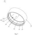
Fig. 3 is a schematic structural diagram of a lamp body inFig. 2 . -
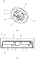
Fig. 4 is a schematic structural diagram of a heat dissipation structure inFig. 2 . -
Fig. 5 is a schematic structural diagram of a light source assembly inFig. 2 . -
Fig. 6 is a cross-sectional view of the lamp shown inFig. 1 . - Reference numeral:
lamp 100;lamp body 10;perforation 11;first shell 12;top plate 121;annular side plate 122;second shell 13;accommodating cavity 14;mating part 15;lead hole 16; connectingpart 17;heat dissipation structure 20;blind hole 21; connectingpart 22;protrusion 23; first connectingplate 24; second connectingplate 25;cavity 26;positioning part 27; opening 28;light source assembly 30; throughhole 31; connectinghole 32;light source plate 33;lamp bead 34;notch 35; light-transmittingcover 40;fasteners 50. - In order to make the objective, technical solution and advantages of the present disclosure more apparent, the present disclosure will be described in details in connection with accompanying drawings and specific embodiments.
- Here, it should be noted that in order to avoid obscuring the present disclosure with unnecessary details, only the structures and/or processing steps closely related to the solution of the present disclosure are shown in the accompanying drawings, while other details that are not much related to the present disclosure have been omitted.
- In addition, it should be noted that the terms "comprising", "including" or any other variations thereof are intended to cover non-exclusive inclusion, so that a process, method, article or equipment including a series of elements includes not only those elements, but also other elements not explicitly listed, or elements inherent to such process, method, article or equipment.
- As shown in
Fig. 1 ,Fig. 2 andFig. 6 , the present disclosure discloses alamp 100, which includes alamp body 10, aheat dissipation structure 20, alight source assembly 30, a light-transmittingcover 40 and afastener 50 for connecting thelamp body 10 and theheat dissipation structure 20. Thelight source assembly 30, theheat dissipation structure 20 and thelamp body 10 are assembled in sequence, and the light-transmittingcover 40 is assembled finally. Thelamp body 10 is provided with at least oneperforation 11; one side of theheat dissipation structure 20 facing towards thelamp body 10 is provided with ablind hole 21 corresponding to theperforation 11; and thefastener 50 passes through theperforation 11 to be connected with theblind hole 21, so as to fixedly connect thelamp body 10 and theheat dissipation structure 20 and to reduce a gap between theheat dissipation structure 20 and thelamp body 10. With this arrangement, it not only ensures a safe creepage distance of thelamp 100 and maintain a physical isolation in existing lamps of the same type as thelamp 100, but also stretches theheat dissipation structure 20 for flattening to avoid a deformation of theheat dissipation structure 20, so as to reduce a connection gap between theheat dissipation structure 20 and each of thelamp body 10 and thelight source assembly 30, thereby reducing a heat dissipation path from thelight source assembly 30 to thelamp body 10 in thelamp 100. - Referring to
Fig. 2 in combination withFig. 3 , thelamp body 10 includes afirst shell 12 and asecond shell 13 surrounding an outer side of thefirst shell 12; aperforation 11 is formed at the top of thefirst shell 12 and penetrates through thefirst shell 12. Anaccommodating cavity 14 is formed inside thefirst shell 12, and theheat dissipation structure 20 is accommodated in theaccommodating cavity 14 and attached to the top of thefirst shell 12. Specifically, thefirst shell 12 includes atop plate 121 and anannular side plate 122 connected with a peripheral edge of thetop plate 121; one end of theannular side plate 122 away from thetop plate 121 extends in a circumferential direction and is connected with thesecond shell 13. With such arrangement, thelamp body 10 can be formed as a double-shell structure, so that thesecond shell 13 can be used to shield a connection structure between thelamp body 10 and theheat dissipation structure 20, which enables thewhole lamp 100 to be more artistic. In this embodiment, thelamp 100 is a downlight, and both thefirst shell 12 and thesecond shell 13 are in a cylindrical shape, but the present disclosure is not limited thereto. - In this embodiment, the
perforation 11 is formed in thetop plate 121, and thefastener 50 directly passes through thetop plate 121 until it is connected with theblind hole 21, so that thelamp body 10 and theheat dissipation structure 20 can be fixedly connected. In addition, the light-transmittingcover 40 is further accommodated in theaccommodating cavity 14. Specifically, a connectingpart 17 for fixing the light-transmittingcover 40 is arranged at the bottom of thefirst shell 12, close to a joint between thefirst shell 12 and thesecond shell 13. The connectingpart 17 is arranged in an annular shape and is arranged on an inner side wall of thefirst shell 12 to be snap-fitted with the light-transmittingcover 40, so that the light-transmittingcover 40 is fixedly accommodated in theaccommodating cavity 14, which can not only ensure a full diffusion of light, but also protect the light-transmittingcover 40 from being damaged. The specific type of the light-transmittingcover 40, as well as the specific assembling mode between the light-transmittingcover 40 and thelamp body 10 are not limited in the present disclosure, and the existing assembling solution can be adopted or adjusted adaptively according to actual situations. - Referring to
Figs. 2 ,3 and4 , theheat dissipation structure 20 includes a first connectingplate 24 and a second connectingplate 25 surrounding the first connectingplate 24. The first connectingplate 24 is in a circular shape, and the second connectingplate 25 is in an annular shape, so as to form acavity 26 for accommodating thelight source assembly 30 between the first connectingplate 24 and the second connectingplate 25. The first connectingplate 24 of theheat dissipation structure 20 is attached to thetop plate 121 of thefirst shell 12; and the second connectingplate 25 is attached to theannular side plate 122. Specifically, theblind hole 21 is arranged on the first connectingplate 24; preferably, the first connectingplate 24 is provided with aprotrusion 23 protruding towards thelight source assembly 30; and theblind hole 21 is arranged in theprotrusion 23. Of course, in the case that the first connectingplate 24 is thick enough, the blind hole can be directly formed in the first connectingplate 24 and the protrusion may be not provided, which is not limited in the present disclosure. - In this embodiment, the
fastener 50 is preferably a screw, theperforation 11 is preferably a screw hole, and an inner wall surface of theblind hole 21 is also provided with a screw thread correspondingly; in this way, the screw can pass through the screw hole and be locked and fixed in theblind hole 21, so that theheat dissipation structure 20 can be stretched for flattening and the first connectingplate 24 of theheat dissipation structure 20 can be closely attached onto thetop plate 121 of thelamp body 10, thereby reducing the gap between theheat dissipation structure 20 and thelamp body 10, and hence shortening the heat conduction path between theheat dissipation structure 20 and thelamp body 10. - The
light source assembly 30 is provided with athrough hole 31 corresponding to theprotrusion 23, and theprotrusion 23 is inserted into the throughhole 31. Specifically, thelight source assembly 30 includes alight source plate 33 and alamp bead 34 fixed on thelight source plate 33. The throughhole 31 is arranged on thelight source plate 33, and theprotrusion 23 is inserted into thethrough hole 31, which not only can limit the connection between thelight source assembly 30 and theheat dissipation structure 20, but also can make thewhole lamp 100 thinner and lighter. - The
heat dissipation structure 20 is further provided with a connectingpart 22 protruding towards thelight source assembly 30, and the connectingpart 22 is in direct contact with thelight source assembly 30, so as to further reduce the connection gap between thelight source assembly 30 and theheat dissipation structure 20, that is, the heat dissipation path. Specifically, the connectingpart 22 is arranged on the first connectingplate 24, and thelight source plate 33 is provided with a connectinghole 32 corresponding to the connectingpart 22, and the connectingpart 22 is tightly fitted with the connectinghole 32. Preferably, the connectingpart 22 passes through the connectinghole 32 to be connected with thelight source assembly 30 by hot melting. On the one hand, thelight source assembly 30 can be in direct contact with theheat dissipation structure 20, and on the other hand, thelight source assembly 30 and theheat dissipation structure 20 can be restricted from moving randomly, so that the connection between thelight source assembly 30 and theheat dissipation structure 20 has better stability. Preferably, the connectingpart 22 is a limiting post, and thelimiting post 22 is connected with thelight source assembly 30 by hot melting. Of course, the connection between the connectingpart 22 and thelight source assembly 30 is not limited to be connected by hot melting, but can also be connected by ultrasonic welding, gluing, etc., as long as the connectingpart 22 and thelight source assembly 30 can be connected with each other, which is not particularly limited here. - An outer side wall of the second connecting
plate 25 is provided with apositioning part 27, and an inner side wall of thefirst shell 12 is correspondingly provided with amating part 15. Thepositioning part 27 and themating part 15 are fitted with each other so that theheat dissipation structure 20 is accommodated and fixed in theaccommodating cavity 14. Preferably, the positioningportion 27 is a hook provided on the second connectingplate 25, and themating part 15 is a protrusion rib provided on the inner side wall of thefirst shell 12. In the present disclosure, theheat dissipation structure 20 and thelamp body 10 are preferably in a circular shape. In this case, themating part 15 is an annular protrusion rib arranged on the inner side wall of thefirst shell 12, and a plurality of hooks are arranged and evenly distributed on the outer side wall of the second connectingplate 25. Of course, thepositioning part 27 and themating part 15 can also have other structures, as long as theheat dissipation structure 20 can be accommodated and fixed in theaccommodating cavity 14, which is not particularly limited here. With the arrangement of thepositioning part 27 and themating part 15, thelamp body 10 and theheat dissipation structure 20 can be fixed in advance, so that they can be fixedly connected again by using thefasteners 50 later. - With combined reference to
Fig. 2 ,Fig. 3 ,Fig. 4 andFig. 5 , thelamp body 10 is further provided with alead hole 16 for wiring connection, and theheat dissipation structure 20 is further provided with a columnar-shapedopening 28 corresponding to thelead hole 16. In order to safely connect the wirings with thelight source assembly 30, anotch 35 is provided at the edge of thelight source plate 33. The wirings sequentially pass through thelead hole 16 and theopening 28, and are pressed into thenotch 35, so as to be electrically connected with thelight source assembly 30. - In order to clearly explain the structural principle of the
lamp 100, the assembling process of thelamp 100 will be described in details below. In the present disclosure, thelamp body 10 is preferably ametal lamp body 10 having thermal conductivity property, and theheat dissipation structure 20 is preferably an insulating plastic part. Firstly, thelight source assembly 30 is placed into thecavity 26 of theheat dissipation structure 20; and theprotrusion 23 and the connectingpart 22 on theheat dissipation structure 20 are inserted into the throughhole 31 and the connectinghole 32 on thelight source plate 33, respectively; and then the connectingpart 22 is fixedly connected with thelight source plate 33 by hot melting. Then, theheat dissipation structure 20 assembled with thelight source assembly 30 is placed in theaccommodating cavity 14 of thelamp body 10, and thepositioning part 27 on theheat dissipation structure 20 is fixedly connected with themating part 15 on thelamp body 10, so that theheat dissipation structure 20 and thelamp body 10 are snap-fitted with each other and positioned. Then, thefastener 50 is inserted through theperforation 11 in thelamp body 10 until it is connected with theblind hole 21, so that thefastener 50 is fixedly locked to lock and fix theheat dissipation structure 20 and thelamp body 10. Finally, the light-transmittingcover 40 and thelamp body 10 are assembled and fixed, and the assembling process of thelamp 100 is completed. - After the light energy generated by the
lamp bead 34 on thelight source assembly 30 is converted into heat, the heat dissipation path of thewhole lamp 100 is as follows: the heat is transmitted from thelamp bead 34 to thelight source plate 33, then from thelight source plate 33 to theheat dissipation structure 20, then from theheat dissipation structure 20 to thelamp body 10, and finally thelamp body 10 transmits the heat out of thelamp 100. By reducing the gap between theheat dissipation structure 20 and thelamp body 10 and the gap between theheat dissipation structure 20 and thelight source plate 33, the heat dissipation efficiency of thewhole lamp 100 is improved. - To sum up, in the
lamp 100 of the present disclose, thelamp body 10 is provided with aperforation 11 while theheat dissipation structure 20 is provided with ablind hole 21 corresponding to theperforation 11, so that thefastener 50 can pass through theperforation 11 to be connected with theblind hole 21; in this way, theheat dissipation structure 20 can be stretched for flattening, so as to shorten the heat dissipation path between theheat dissipation structure 20 and each of thelamp body 10 and thelight source assembly 30, thereby improving the heat dissipation rate of the whole lamp, and prolonging the service life of thelamp 100. - The above embodiments are only used to illustrate the technical solution of the present disclosure, but are not intended to limit the present disclosure. Although the present disclosure has been described in details with reference to the preferred embodiments, it should be understood by those ordinary skilled in the art that the technical solution of the present disclosure can be modified or replaced by equivalents without departing from the spirit and scope of the technical solution of the present disclosure.
Claims (10)
- A lamp, comprising a lamp body (10) and a light source assembly (30) arranged in the lamp body, wherein the lamp further comprises a heat dissipation structure (20) as well as a fastener (50) located between the lamp body (10) and the light source assembly (30); the lamp body (10) is provided with at least one perforation (11), and one side of the heat dissipation structure (20) facing towards the lamp body (10) is provided with a blind hole (21) corresponding to the perforation (11); the fastener (50) is configured to pass through the perforation (11) to be connected with the blind hole (21) so as to reduce a gap between the heat dissipation structure (20) and the lamp body (10); a connecting part (22) is arranged on one side of the heat dissipation structure (20) facing towards the light source assembly (30), and the connecting part (22) is connected with the light source assembly (30) to reduce a gap between the light source assembly (30) and the heat dissipation structure (20).
- The lamp according to claim 1, wherein the heat dissipation structure (20) is provided with a protrusion (23) protruding towards the light source assembly (30), the blind hole (21) is arranged in the protrusion (23), and the light source assembly (30) is provided with a through hole (31) corresponding to the protrusion (23), wherein the protrusion (23) is inserted into the through hole (31) to limit a connection between the light source assembly (30) and the heat dissipation structure (20).
- The lamp according to claim 1, wherein the light source assembly (30) is further provided with a connecting hole (32) corresponding to the connecting part (22), and the connecting part (22) is tightly fitted with the connecting hole (32).
- The lamp according to claim 1, wherein the light source assembly (30) is further provided with a connecting hole (32) corresponding to the connecting part (22), and the connecting part (22) passes through the connecting hole (32) to be connected with the light source assembly (30) by means of hot melting.
- The lamp according to claim 1, wherein the lamp body (10) comprises a first shell (12) and a second shell (13)surrounding an outer side of the first shell (12); the perforation (11) is formed at a top of the first shell (12) and penetrates through the first shell (12); an accommodating chamber (14) is formed inside the first shell (12), and the heat dissipation structure (20) is accommodated in the accommodating chamber (14) and is attached to the top of the first shell (12).
- The lamp according to claim 5, wherein the heat dissipation structure (20) comprises a first connecting plate (24) and a second connecting plate (25) surrounding the first connecting plate (24), and both the connecting part (22) and the blind hole (21) are arranged on the first connecting plate (24); an outer side wall of the second connecting plate (25) is provided with a positioning part (27), an inner side wall of the first shell (12) is correspondingly provided with a mating part (15), and the positioning part (27) and the mating part (15) are fitted with each other so that the heat dissipation structure (20) is accommodated and fixed in the accommodating cavity (14).
- The lamp according to claim 6, wherein the first shell (12) comprises a top plate and an annular side plate connected with a peripheral edge of the top plate; one end of the annular side plate away from the top plate is connected with the second shell (13), the perforation (11) is arranged on the top plate, the first connecting plate (24) of the heat dissipation structure (20) is attached to the top plate, and the second connecting plate (25) of the heat dissipation structure (20) is attached to the annular side plate.
- The lamp according to claim 6, wherein the positioning part (27) is a hook arranged on the second connecting plate (25), and the mating part (15) is a protrusion rib arranged on the inner side wall of the first shell (12).
- The lamp according to claim 8, wherein the heat dissipation structure (20) and the lamp body (10) are both in a circular shape, the mating part (15) is an annular protrusion rib arranged on the inner side wall of the first shell (12), and a plurality of hooks are arranged and evenly distributed on the outer side wall of the second connecting plate (25).
- The lamp according to claim 1, wherein the fastener (50) is a screw, the perforation (11) is a screw hole, the heat dissipation structure (20) is an insulating plastic part, and the lamp body (10) is a metal lamp body.
Applications Claiming Priority (2)
| Application Number | Priority Date | Filing Date | Title |
|---|---|---|---|
| CN202123130705.XU CN216667616U (en) | 2021-12-14 | 2021-12-14 | Lamp fitting |
| PCT/CN2022/137984 WO2023109681A1 (en) | 2021-12-14 | 2022-12-09 | Lamp |
Publications (2)
| Publication Number | Publication Date |
|---|---|
| EP4450869A1 true EP4450869A1 (en) | 2024-10-23 |
| EP4450869A4 EP4450869A4 (en) | 2025-04-23 |
Family
ID=81789680
Family Applications (1)
| Application Number | Title | Priority Date | Filing Date |
|---|---|---|---|
| EP22906429.0A Pending EP4450869A4 (en) | 2021-12-14 | 2022-12-09 | LAMP |
Country Status (4)
| Country | Link |
|---|---|
| US (1) | US12259117B2 (en) |
| EP (1) | EP4450869A4 (en) |
| CN (1) | CN216667616U (en) |
| WO (1) | WO2023109681A1 (en) |
Families Citing this family (1)
| Publication number | Priority date | Publication date | Assignee | Title |
|---|---|---|---|---|
| CN216667616U (en) | 2021-12-14 | 2022-06-03 | 欧普照明股份有限公司 | Lamp fitting |
Family Cites Families (22)
| Publication number | Priority date | Publication date | Assignee | Title |
|---|---|---|---|---|
| JP3908113B2 (en) * | 2002-07-30 | 2007-04-25 | 株式会社住友金属エレクトロデバイス | Heat dissipation type BGA package and manufacturing method thereof |
| CN101825236B (en) * | 2009-03-07 | 2013-04-24 | 富准精密工业(深圳)有限公司 | Light-emitting diode lamp |
| TW201043844A (en) * | 2009-06-01 | 2010-12-16 | Yu-Lin Chu | Heat dissipating structure for LED lamp |
| KR101285889B1 (en) * | 2010-06-23 | 2013-07-11 | 엘지전자 주식회사 | LED lighting fixtures |
| WO2013044636A1 (en) * | 2011-09-30 | 2013-04-04 | Yang Dongzuo | Led lamp |
| TWI481799B (en) * | 2012-06-19 | 2015-04-21 | Taiwan Fu Hsing Ind Co Ltd | Lamp structure |
| US20140153277A1 (en) * | 2012-11-30 | 2014-06-05 | Liang Meng Plastic Share Co., Ltd. | Assembling structure for led lamp module |
| CN205037079U (en) * | 2013-01-29 | 2016-02-17 | 三菱化学株式会社 | LED lighting |
| CN103629646A (en) * | 2013-12-03 | 2014-03-12 | 匡正芳 | LED (Light Emitting Diode) lamp with heat-conduction plastic heat radiator |
| CN204042526U (en) * | 2014-08-15 | 2014-12-24 | 佛山市崇达照明电器有限公司 | A kind of Novel LED light |
| CN105546456A (en) * | 2016-02-19 | 2016-05-04 | 上海信耀电子有限公司 | Vehicle lamp with excellent heat dissipation |
| CN106764516A (en) * | 2017-03-21 | 2017-05-31 | 宁波亚茂光电股份有限公司 | A kind of LED for replacing indoor wall lamp |
| TWM547065U (en) * | 2017-04-14 | 2017-08-11 | 軒帆光電科技股份有限公司 | Light source module for illumination device |
| KR101934033B1 (en) * | 2017-06-07 | 2018-12-31 | 이노컴퍼니(주) | LED floodlight having reinforced heat radiant function |
| JP7285463B2 (en) * | 2019-04-18 | 2023-06-02 | パナソニックIpマネジメント株式会社 | Illumination light source and illumination device |
| CN110440218B (en) * | 2019-09-20 | 2024-12-10 | 嘉兴市光泰照明有限公司 | LED automobile lamp |
| CN211853708U (en) * | 2019-12-30 | 2020-11-03 | 漳州立达信光电子科技有限公司 | LED (light-emitting diode) down lamp |
| CN211176493U (en) * | 2020-01-22 | 2020-08-04 | 伊顿智能动力有限公司 | Explosion-proof lamp |
| US11774046B2 (en) * | 2020-03-12 | 2023-10-03 | Zhejiang Yankon Mega Lighting Co., Ltd. | LED light source assembly and high-power lamp using the same |
| CN211780294U (en) * | 2020-05-15 | 2020-10-27 | 华荣科技股份有限公司 | Fixed LED lamps and lanterns have strong heat dissipation |
| CN112097130A (en) * | 2020-10-12 | 2020-12-18 | 深圳市宝明达半导体照明有限公司 | LED lamp |
| CN216667616U (en) * | 2021-12-14 | 2022-06-03 | 欧普照明股份有限公司 | Lamp fitting |
-
2021
- 2021-12-14 CN CN202123130705.XU patent/CN216667616U/en active Active
-
2022
- 2022-12-09 EP EP22906429.0A patent/EP4450869A4/en active Pending
- 2022-12-09 WO PCT/CN2022/137984 patent/WO2023109681A1/en not_active Ceased
-
2024
- 2024-06-14 US US18/744,101 patent/US12259117B2/en active Active
Also Published As
| Publication number | Publication date |
|---|---|
| CN216667616U (en) | 2022-06-03 |
| US12259117B2 (en) | 2025-03-25 |
| WO2023109681A1 (en) | 2023-06-22 |
| US20240337374A1 (en) | 2024-10-10 |
| EP4450869A4 (en) | 2025-04-23 |
Similar Documents
| Publication | Publication Date | Title |
|---|---|---|
| EP3974705A1 (en) | Down light | |
| US20130077297A1 (en) | Led fluorescent tube structure | |
| US12259117B2 (en) | Lamp | |
| JP5569372B2 (en) | Lamp and lamp device | |
| US6238062B1 (en) | Modified lamp series | |
| CN203336403U (en) | Led ceiling lamp | |
| CN221881392U (en) | Lighting | |
| CN104633464B (en) | LED portable lamp | |
| CN219867604U (en) | Tube lamp | |
| KR200455032Y1 (en) | Fluorescent lamp type LED lamp | |
| US11441744B2 (en) | Elongated frame lamp | |
| CN215637054U (en) | Heat radiation structure of long down lamp | |
| CN209130832U (en) | A light source board heat dissipation structure and lamp | |
| CN209991226U (en) | Light source board fixed knot constructs and ball bubble lamp | |
| WO2020088310A1 (en) | Candle bulb lamp | |
| JP3227587U (en) | Diagonal LED light | |
| CN210891136U (en) | Annular lamp | |
| CN205278799U (en) | Flame -proof type explosion -proof lamp lamp shade and explosion -proof lamp | |
| CN219063270U (en) | Light projector | |
| JP6418277B2 (en) | lamp | |
| JP2017037708A (en) | Compact fluorescent LED lamp | |
| CN215446101U (en) | Lamp with improved fixing structure | |
| JP2013010290A (en) | Method of manufacturing bulb lamp housing | |
| CN222363857U (en) | LED Bulbs | |
| JP2013235849A (en) | Lamp with base, and lighting fixture |
Legal Events
| Date | Code | Title | Description |
|---|---|---|---|
| STAA | Information on the status of an ep patent application or granted ep patent |
Free format text: STATUS: THE INTERNATIONAL PUBLICATION HAS BEEN MADE |
|
| PUAI | Public reference made under article 153(3) epc to a published international application that has entered the european phase |
Free format text: ORIGINAL CODE: 0009012 |
|
| STAA | Information on the status of an ep patent application or granted ep patent |
Free format text: STATUS: REQUEST FOR EXAMINATION WAS MADE |
|
| 17P | Request for examination filed |
Effective date: 20240715 |
|
| AK | Designated contracting states |
Kind code of ref document: A1 Designated state(s): AL AT BE BG CH CY CZ DE DK EE ES FI FR GB GR HR HU IE IS IT LI LT LU LV MC ME MK MT NL NO PL PT RO RS SE SI SK SM TR |
|
| DAV | Request for validation of the european patent (deleted) | ||
| DAX | Request for extension of the european patent (deleted) | ||
| A4 | Supplementary search report drawn up and despatched |
Effective date: 20250320 |
|
| RIC1 | Information provided on ipc code assigned before grant |
Ipc: F21V 19/00 20060101ALI20250314BHEP Ipc: F21V 29/70 20150101ALI20250314BHEP Ipc: F21V 29/83 20150101ALI20250314BHEP Ipc: F21V 29/503 20150101AFI20250314BHEP |