CN112097130A - LED lamp - Google Patents
LED lamp Download PDFInfo
- Publication number
- CN112097130A CN112097130A CN202011087424.8A CN202011087424A CN112097130A CN 112097130 A CN112097130 A CN 112097130A CN 202011087424 A CN202011087424 A CN 202011087424A CN 112097130 A CN112097130 A CN 112097130A
- Authority
- CN
- China
- Prior art keywords
- heat dissipation
- led lamp
- accommodating cavity
- lens
- dissipation shell
- Prior art date
- Legal status (The legal status is an assumption and is not a legal conclusion. Google has not performed a legal analysis and makes no representation as to the accuracy of the status listed.)
- Pending
Links
Images




Classifications
-
- F—MECHANICAL ENGINEERING; LIGHTING; HEATING; WEAPONS; BLASTING
- F21—LIGHTING
- F21K—NON-ELECTRIC LIGHT SOURCES USING LUMINESCENCE; LIGHT SOURCES USING ELECTROCHEMILUMINESCENCE; LIGHT SOURCES USING CHARGES OF COMBUSTIBLE MATERIAL; LIGHT SOURCES USING SEMICONDUCTOR DEVICES AS LIGHT-GENERATING ELEMENTS; LIGHT SOURCES NOT OTHERWISE PROVIDED FOR
- F21K9/00—Light sources using semiconductor devices as light-generating elements, e.g. using light-emitting diodes [LED] or lasers
- F21K9/20—Light sources comprising attachment means
- F21K9/23—Retrofit light sources for lighting devices with a single fitting for each light source, e.g. for substitution of incandescent lamps with bayonet or threaded fittings
- F21K9/233—Retrofit light sources for lighting devices with a single fitting for each light source, e.g. for substitution of incandescent lamps with bayonet or threaded fittings specially adapted for generating a spot light distribution, e.g. for substitution of reflector lamps
-
- F—MECHANICAL ENGINEERING; LIGHTING; HEATING; WEAPONS; BLASTING
- F21—LIGHTING
- F21K—NON-ELECTRIC LIGHT SOURCES USING LUMINESCENCE; LIGHT SOURCES USING ELECTROCHEMILUMINESCENCE; LIGHT SOURCES USING CHARGES OF COMBUSTIBLE MATERIAL; LIGHT SOURCES USING SEMICONDUCTOR DEVICES AS LIGHT-GENERATING ELEMENTS; LIGHT SOURCES NOT OTHERWISE PROVIDED FOR
- F21K9/00—Light sources using semiconductor devices as light-generating elements, e.g. using light-emitting diodes [LED] or lasers
- F21K9/20—Light sources comprising attachment means
- F21K9/23—Retrofit light sources for lighting devices with a single fitting for each light source, e.g. for substitution of incandescent lamps with bayonet or threaded fittings
- F21K9/232—Retrofit light sources for lighting devices with a single fitting for each light source, e.g. for substitution of incandescent lamps with bayonet or threaded fittings specially adapted for generating an essentially omnidirectional light distribution, e.g. with a glass bulb
-
- F—MECHANICAL ENGINEERING; LIGHTING; HEATING; WEAPONS; BLASTING
- F21—LIGHTING
- F21K—NON-ELECTRIC LIGHT SOURCES USING LUMINESCENCE; LIGHT SOURCES USING ELECTROCHEMILUMINESCENCE; LIGHT SOURCES USING CHARGES OF COMBUSTIBLE MATERIAL; LIGHT SOURCES USING SEMICONDUCTOR DEVICES AS LIGHT-GENERATING ELEMENTS; LIGHT SOURCES NOT OTHERWISE PROVIDED FOR
- F21K9/00—Light sources using semiconductor devices as light-generating elements, e.g. using light-emitting diodes [LED] or lasers
- F21K9/20—Light sources comprising attachment means
- F21K9/23—Retrofit light sources for lighting devices with a single fitting for each light source, e.g. for substitution of incandescent lamps with bayonet or threaded fittings
- F21K9/237—Details of housings or cases, i.e. the parts between the light-generating element and the bases; Arrangement of components within housings or cases
-
- F—MECHANICAL ENGINEERING; LIGHTING; HEATING; WEAPONS; BLASTING
- F21—LIGHTING
- F21K—NON-ELECTRIC LIGHT SOURCES USING LUMINESCENCE; LIGHT SOURCES USING ELECTROCHEMILUMINESCENCE; LIGHT SOURCES USING CHARGES OF COMBUSTIBLE MATERIAL; LIGHT SOURCES USING SEMICONDUCTOR DEVICES AS LIGHT-GENERATING ELEMENTS; LIGHT SOURCES NOT OTHERWISE PROVIDED FOR
- F21K9/00—Light sources using semiconductor devices as light-generating elements, e.g. using light-emitting diodes [LED] or lasers
- F21K9/20—Light sources comprising attachment means
- F21K9/23—Retrofit light sources for lighting devices with a single fitting for each light source, e.g. for substitution of incandescent lamps with bayonet or threaded fittings
- F21K9/238—Arrangement or mounting of circuit elements integrated in the light source
-
- F—MECHANICAL ENGINEERING; LIGHTING; HEATING; WEAPONS; BLASTING
- F21—LIGHTING
- F21V—FUNCTIONAL FEATURES OR DETAILS OF LIGHTING DEVICES OR SYSTEMS THEREOF; STRUCTURAL COMBINATIONS OF LIGHTING DEVICES WITH OTHER ARTICLES, NOT OTHERWISE PROVIDED FOR
- F21V17/00—Fastening of component parts of lighting devices, e.g. shades, globes, refractors, reflectors, filters, screens, grids or protective cages
- F21V17/10—Fastening of component parts of lighting devices, e.g. shades, globes, refractors, reflectors, filters, screens, grids or protective cages characterised by specific fastening means or way of fastening
- F21V17/12—Fastening of component parts of lighting devices, e.g. shades, globes, refractors, reflectors, filters, screens, grids or protective cages characterised by specific fastening means or way of fastening by screwing
-
- F—MECHANICAL ENGINEERING; LIGHTING; HEATING; WEAPONS; BLASTING
- F21—LIGHTING
- F21V—FUNCTIONAL FEATURES OR DETAILS OF LIGHTING DEVICES OR SYSTEMS THEREOF; STRUCTURAL COMBINATIONS OF LIGHTING DEVICES WITH OTHER ARTICLES, NOT OTHERWISE PROVIDED FOR
- F21V17/00—Fastening of component parts of lighting devices, e.g. shades, globes, refractors, reflectors, filters, screens, grids or protective cages
- F21V17/10—Fastening of component parts of lighting devices, e.g. shades, globes, refractors, reflectors, filters, screens, grids or protective cages characterised by specific fastening means or way of fastening
- F21V17/18—Latch-type fastening, e.g. with rotary action
-
- F—MECHANICAL ENGINEERING; LIGHTING; HEATING; WEAPONS; BLASTING
- F21—LIGHTING
- F21V—FUNCTIONAL FEATURES OR DETAILS OF LIGHTING DEVICES OR SYSTEMS THEREOF; STRUCTURAL COMBINATIONS OF LIGHTING DEVICES WITH OTHER ARTICLES, NOT OTHERWISE PROVIDED FOR
- F21V23/00—Arrangement of electric circuit elements in or on lighting devices
- F21V23/003—Arrangement of electric circuit elements in or on lighting devices the elements being electronics drivers or controllers for operating the light source, e.g. for a LED array
- F21V23/007—Arrangement of electric circuit elements in or on lighting devices the elements being electronics drivers or controllers for operating the light source, e.g. for a LED array enclosed in a casing
-
- F—MECHANICAL ENGINEERING; LIGHTING; HEATING; WEAPONS; BLASTING
- F21—LIGHTING
- F21V—FUNCTIONAL FEATURES OR DETAILS OF LIGHTING DEVICES OR SYSTEMS THEREOF; STRUCTURAL COMBINATIONS OF LIGHTING DEVICES WITH OTHER ARTICLES, NOT OTHERWISE PROVIDED FOR
- F21V23/00—Arrangement of electric circuit elements in or on lighting devices
- F21V23/06—Arrangement of electric circuit elements in or on lighting devices the elements being coupling devices, e.g. connectors
-
- F—MECHANICAL ENGINEERING; LIGHTING; HEATING; WEAPONS; BLASTING
- F21—LIGHTING
- F21V—FUNCTIONAL FEATURES OR DETAILS OF LIGHTING DEVICES OR SYSTEMS THEREOF; STRUCTURAL COMBINATIONS OF LIGHTING DEVICES WITH OTHER ARTICLES, NOT OTHERWISE PROVIDED FOR
- F21V29/00—Protecting lighting devices from thermal damage; Cooling or heating arrangements specially adapted for lighting devices or systems
- F21V29/50—Cooling arrangements
- F21V29/70—Cooling arrangements characterised by passive heat-dissipating elements, e.g. heat-sinks
- F21V29/74—Cooling arrangements characterised by passive heat-dissipating elements, e.g. heat-sinks with fins or blades
- F21V29/77—Cooling arrangements characterised by passive heat-dissipating elements, e.g. heat-sinks with fins or blades with essentially identical diverging planar fins or blades, e.g. with fan-like or star-like cross-section
- F21V29/773—Cooling arrangements characterised by passive heat-dissipating elements, e.g. heat-sinks with fins or blades with essentially identical diverging planar fins or blades, e.g. with fan-like or star-like cross-section the planes containing the fins or blades having the direction of the light emitting axis
-
- F—MECHANICAL ENGINEERING; LIGHTING; HEATING; WEAPONS; BLASTING
- F21—LIGHTING
- F21V—FUNCTIONAL FEATURES OR DETAILS OF LIGHTING DEVICES OR SYSTEMS THEREOF; STRUCTURAL COMBINATIONS OF LIGHTING DEVICES WITH OTHER ARTICLES, NOT OTHERWISE PROVIDED FOR
- F21V3/00—Globes; Bowls; Cover glasses
-
- F—MECHANICAL ENGINEERING; LIGHTING; HEATING; WEAPONS; BLASTING
- F21—LIGHTING
- F21V—FUNCTIONAL FEATURES OR DETAILS OF LIGHTING DEVICES OR SYSTEMS THEREOF; STRUCTURAL COMBINATIONS OF LIGHTING DEVICES WITH OTHER ARTICLES, NOT OTHERWISE PROVIDED FOR
- F21V5/00—Refractors for light sources
- F21V5/007—Array of lenses or refractors for a cluster of light sources, e.g. for arrangement of multiple light sources in one plane
-
- F—MECHANICAL ENGINEERING; LIGHTING; HEATING; WEAPONS; BLASTING
- F21—LIGHTING
- F21V—FUNCTIONAL FEATURES OR DETAILS OF LIGHTING DEVICES OR SYSTEMS THEREOF; STRUCTURAL COMBINATIONS OF LIGHTING DEVICES WITH OTHER ARTICLES, NOT OTHERWISE PROVIDED FOR
- F21V5/00—Refractors for light sources
- F21V5/04—Refractors for light sources of lens shape
- F21V5/048—Refractors for light sources of lens shape the lens being a simple lens adapted to cooperate with a point-like source for emitting mainly in one direction and having an axis coincident with the main light transmission direction, e.g. convergent or divergent lenses, plano-concave or plano-convex lenses
-
- F—MECHANICAL ENGINEERING; LIGHTING; HEATING; WEAPONS; BLASTING
- F21—LIGHTING
- F21Y—INDEXING SCHEME ASSOCIATED WITH SUBCLASSES F21K, F21L, F21S and F21V, RELATING TO THE FORM OR THE KIND OF THE LIGHT SOURCES OR OF THE COLOUR OF THE LIGHT EMITTED
- F21Y2115/00—Light-generating elements of semiconductor light sources
- F21Y2115/10—Light-emitting diodes [LED]
Landscapes
- Engineering & Computer Science (AREA)
- General Engineering & Computer Science (AREA)
- Microelectronics & Electronic Packaging (AREA)
- Physics & Mathematics (AREA)
- Optics & Photonics (AREA)
- Arrangement Of Elements, Cooling, Sealing, Or The Like Of Lighting Devices (AREA)
- Non-Portable Lighting Devices Or Systems Thereof (AREA)
Abstract
本发明公开一种LED灯具,包括散热壳体、设置在散热壳体顶部的防眩光灯罩、设置在散热壳体底部的电源座、以及依次置于散热壳体内的聚光组件与LED光源板;所述散热壳体的外侧设有若干散热肋骨,顶部设有若干散热孔;所述聚光组件包括若干支撑架、以及设置在每一支撑架上的一透镜,所述支撑架的上设有若干卡扣,所述透镜上设有与卡扣相对的卡槽;所述透镜通过卡槽与支撑架的卡槽卡合。本发明灯具散热好,工耗小,节能出色,能用同等亮度80WLED灯代替1000W卤素灯,使用寿命长;散热壳体与电源座通过内部螺丝固定,避免螺丝长期置于外部而生锈,影响使用寿命。

The invention discloses an LED lamp, comprising a heat dissipation shell, an anti-glare lampshade arranged on the top of the heat dissipation shell, a power base disposed at the bottom of the heat dissipation shell, and a condensing assembly and an LED light source board sequentially placed in the heat dissipation shell; The outer side of the heat dissipation shell is provided with a number of heat dissipation ribs, and the top is provided with a number of heat dissipation holes; the light-condensing assembly includes a number of support frames, and a lens arranged on each support frame, and the support frame is provided with a lens. A plurality of clips are provided, and the lens is provided with a slot opposite to the clip; the lens is engaged with the slot of the support frame through the slot. The lamp of the invention has good heat dissipation, low labor consumption, excellent energy saving, can replace 1000W halogen lamp with 80W LED lamp of the same brightness, and has a long service life; service life.
Description
技术领域technical field
本发明涉及LED灯技术领域,特别涉及一种LED灯具。The invention relates to the technical field of LED lamps, in particular to an LED lamp.
背景技术Background technique
现市场上只有PAR64白炽灯卤素灯光源,通常功率是500W和1000W,功耗大,发热量高,使用寿命短(2000小时左右),玻璃外壳易碎,现有的PAR64 使用用场景简单,使用色彩单一,散热效果差,严重影响使用寿命。There are only PAR64 incandescent halogen light sources on the market, usually 500W and 1000W, with large power consumption, high calorific value, short service life (about 2000 hours), and the glass shell is fragile. The existing PAR64 use scenarios are simple and easy to use The color is single, the heat dissipation effect is poor, and the service life is seriously affected.
发明内容SUMMARY OF THE INVENTION
针对现有技术存在的问题,本发明提供一种LED灯具,具有散热效果、寿命长、聚光及防眩目的优点。In view of the problems existing in the prior art, the present invention provides an LED lamp, which has the advantages of heat dissipation effect, long service life, light gathering and anti-glare.
为了实现上述目的,本发明技术方案如下:In order to achieve the above object, the technical scheme of the present invention is as follows:
一种LED灯具,包括散热壳体、设置在散热壳体顶部的防眩光灯罩、设置在散热壳体底部的电源座、以及依次置于散热壳体内的聚光组件与LED光源板;所述散热壳体的外侧设有若干散热肋骨,顶部设有若干散热孔;所述聚光组件包括若干支撑架、以及设置在每一支撑架上的一透镜,所述支撑架的上设有若干卡扣,所述透镜上设有与卡扣相对的卡槽;所述透镜通过卡槽与支撑架的卡槽卡合。An LED lamp includes a heat dissipation shell, an anti-glare lampshade disposed on the top of the heat dissipation shell, a power base disposed at the bottom of the heat dissipation shell, and a condensing component and an LED light source plate sequentially placed in the heat dissipation shell; the heat dissipation The outer side of the casing is provided with a number of heat dissipation ribs, and the top is provided with a number of heat dissipation holes; the light-concentrating assembly includes a number of support frames, and a lens arranged on each support frame, and a plurality of buckles are arranged on the support frame , the lens is provided with a card slot opposite to the buckle; the lens is engaged with the card slot of the support frame through the card slot.
较佳地,所述电源座上设有第一容纳腔体且该第一容纳腔体为六边形的棱柱形腔,所述第一容纳腔体的侧壁上设有若干细长的插槽;该细长的插槽具有相同的方向,与第一容纳腔的轴向一致。Preferably, the power socket is provided with a first accommodating cavity and the first accommodating cavity is a hexagonal prismatic cavity, and the side wall of the first accommodating cavity is provided with a plurality of elongated sockets. slot; the elongated slot has the same direction, which is consistent with the axial direction of the first accommodating cavity.
较佳地,所述散热壳体的开口处的内环板上开设有与插槽一一相对的第一通孔;所述LED灯具还包括若干第一螺丝、若干第二螺丝;每一所述第一螺丝均穿过一对应的第一通孔置于一插槽内,将电源座与散热壳体固定。Preferably, the inner ring plate at the opening of the heat dissipation shell is provided with first through holes that are opposite to the slots one by one; the LED lamp further includes a plurality of first screws and a plurality of second screws; The first screws pass through a corresponding first through hole and are placed in a slot to fix the power base and the heat dissipation housing.
较佳地,所述PAR64灯还包括一驱动电源;所述驱动电源置于电源座的第一容纳腔内;所述驱动电源的输出端子与LED光源板电性连接。Preferably, the PAR64 lamp further includes a driving power supply; the driving power supply is placed in the first accommodating cavity of the power supply base; the output terminal of the driving power supply is electrically connected with the LED light source board.
较佳地,所述LED灯具还包括一基板;所述驱动电源设置在基板上。Preferably, the LED lamp further includes a substrate; the driving power source is arranged on the substrate.
较佳地,所述基板每一侧对应设有两第二通孔,对应的第二螺丝穿过第二通孔将基板固定。Preferably, each side of the base plate is provided with two second through holes correspondingly, and the corresponding second screws pass through the second through holes to fix the base plate.
较佳地,所述电源座底部还设有接电插脚,该接电插脚与驱动电源的输入端电性连接。Preferably, the bottom of the power socket is further provided with an electrical connection pin, and the electrical connection pin is electrically connected with the input end of the driving power supply.
较佳地,所述透镜支撑架设有第二容纳腔体,该第二容纳腔体为六边形的棱柱形腔且与第一容纳腔体形状相同,能随着第一容纳腔体形状的变化而变化。Preferably, the lens support frame is provided with a second accommodating cavity, the second accommodating cavity is a hexagonal prismatic cavity and has the same shape as the first accommodating cavity, and can follow the shape of the first accommodating cavity. change with change.
较佳地,所述散热壳体选自铝冷煅一体成型或陶瓷一体成型。Preferably, the heat dissipating shell is selected from aluminum cold forging integral molding or ceramic integral molding.
采用本发明的技术方案,具有以下有益效果:本发明灯具散热好,工耗小,节能出色,能用同等亮度80WLED灯代替1000W卤素灯,使用寿命长(35000 小时以上);散热壳体与电源座通过内部螺丝固定,避免螺丝长期置于外部而生锈,影响使用寿命;支架与透镜卡合式连接,使透镜固定在支架上,不容易松动,避免影响聚光效果。The technical scheme of the present invention has the following beneficial effects: the lamp of the present invention has good heat dissipation, low labor consumption, excellent energy saving, can replace 1000W halogen lamp with an 80W LED lamp of the same brightness, and has a long service life (more than 35,000 hours); The seat is fixed by internal screws to prevent the screws from being rusted outside for a long time, which will affect the service life; the bracket is connected with the lens in a snap-type connection, so that the lens is fixed on the bracket, and it is not easy to loosen, so as to avoid affecting the condensing effect.
附图说明Description of drawings
图1为本发明结构示意图;Fig. 1 is the structural representation of the present invention;
图2为本发明结构爆炸图;2 is an exploded view of the structure of the present invention;
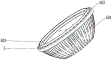
图3为本发明散热壳体结构示意图;FIG. 3 is a schematic diagram of the structure of the heat dissipation housing of the present invention;
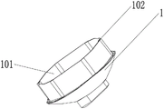
图4为本发明电源座结构示意图;FIG. 4 is a schematic structural diagram of a power socket according to the present invention;
图5为本发明支撑架结构示意图;Figure 5 is a schematic diagram of the structure of the support frame of the present invention;
图6为本发明透镜结构示意图。FIG. 6 is a schematic diagram of the lens structure of the present invention.
具体实施方式Detailed ways
下面详细描述本发明的实施例,所述实施例的示例在附图中示出,其中自始至终相同或类似的标号表示相同或类似的元件或具有相同或类似功能的元件。下面通过参考附图描述的实施例是示例性的,旨在用于解释本发明,而不能理解为对本发明的限制。The following describes in detail the embodiments of the present invention, examples of which are illustrated in the accompanying drawings, wherein the same or similar reference numerals refer to the same or similar elements or elements having the same or similar functions throughout. The embodiments described below with reference to the accompanying drawings are exemplary, and are intended to explain the present invention and should not be construed as limiting the present invention.
在本发明的描述中,需要理解的是,术语“中心”、“纵向”、“横向”、“长度”、“宽度”、“厚度”、“上”、“下”、“前”、“后”、“左”、“右”、“竖直”、“水平”、“顶”、“底”“内”、“外”、“顺时针”、“逆时针”等指示的方位或位置关系为基于附图所示的方位或位置关系,仅是为了便于描述本发明和简化描述,而不是指示或暗示所指的装置或元件必须具有特定的方位、以特定的方位构造和操作,因此不能理解为对本发明的限制。In the description of the present invention, it should be understood that the terms "center", "longitudinal", "lateral", "length", "width", "thickness", "upper", "lower", "front", " Rear", "left", "right", "vertical", "horizontal", "top", "bottom", "inside", "outside", "clockwise", "counterclockwise", etc. The relationship is based on the orientation or positional relationship shown in the drawings, which is only for the convenience of describing the present invention and simplifying the description, rather than indicating or implying that the device or element referred to must have a particular orientation, be constructed and operated in a particular orientation, and therefore It should not be construed as a limitation of the present invention.
此外,术语“第一”、“第二”仅用于描述目的,而不能理解为指示或暗示相对重要性或者隐含指明所指示的技术特征的数量。由此,限定有“第一”、“第二”的特征可以明示或者隐含地包括一个或者更多个该特征。在本发明的描述中,“多个”的含义是两个或两个以上,除非另有明确具体的限定。In addition, the terms "first" and "second" are only used for descriptive purposes, and should not be construed as indicating or implying relative importance or implying the number of indicated technical features. Thus, a feature defined as "first", "second" may expressly or implicitly include one or more of that feature. In the description of the present invention, "plurality" means two or more, unless otherwise expressly and specifically defined.
在本发明中,除非另有明确的规定和限定,术语“安装”、“相连”、“连接”、“固定”等术语应做广义理解,例如,可以是固定连接,也可以是可拆卸连接,或一体地连接;可以是机械连接,也可以是电连接;可以是直接相连,也可以通过中间媒介间接相连,可以是两个元件内部的连通。对于本领域的普通技术人员而言,可以根据具体情况理解上述术语在本发明中的具体含义。In the present invention, unless otherwise expressly specified and limited, the terms "installed", "connected", "connected", "fixed" and other terms should be understood in a broad sense, for example, it may be a fixed connection or a detachable connection , or integrally connected; it can be a mechanical connection or an electrical connection; it can be a direct connection, or an indirect connection through an intermediate medium, or the internal communication between the two components. For those of ordinary skill in the art, the specific meanings of the above terms in the present invention can be understood according to specific situations.
在本发明中,除非另有明确的规定和限定,第一特征在第二特征之“上”或之In the present invention, unless otherwise expressly specified and limited, the first feature is "on" or "on" the second feature
“下”可以包括第一和第二特征直接接触,也可以包括第一和第二特征不是直接接触而是通过它们之间的另外的特征接触。而且,第一特征在第二特征“之上”、“上方”和“上面”包括第一特征在第二特征正上方和斜上方,或仅仅表示第一特征水平高度高于第二特征。第一特征在第二特征“之下”、“下方”和“下面”包括第一特征在第二特征正下方和斜下方,或仅仅表示第一特征水平高度小于第二特征。"Under" may include that the first and second features are in direct contact, or that the first and second features are not in direct contact but are in contact through another feature therebetween. Also, the first feature being "above", "over" and "above" the second feature includes the first feature being directly above and obliquely above the second feature, or simply means that the first feature is level higher than the second feature. The first feature is "below", "below" and "below" the second feature includes the first feature being directly below and diagonally below the second feature, or simply means that the first feature has a lower level than the second feature.
参照图1至图6,本发明提供一种LED灯具,包括散热壳体5、设置在散热壳体5顶部的防眩光灯罩9、设置在散热壳体5底部的电源座1、以及依次置于散热壳体5内的聚光组件与LED光源板6;其中聚光组件与防眩光灯罩9的配合设计,是为了避免人眼因灯光的扩散使眼眩目,另外使灯聚光,使灯具的功率的使用率;所述散热壳体5的外侧设有若干散热肋骨501,这样的设计方式,可以在使用的过程中,方便空气的流通,从而使现LED光源板在使用过程起到散热的效果;顶部设有若干散热孔502,这样的设计方式为配合散热肋骨501 使ED光源板的热时更容易散出;所述聚光组件包括若干支撑架7、以及设置在每一支撑架7上的一透镜8,所述支撑架7的上设有若干卡扣701,所述透镜8上设有与卡扣701相对的卡槽801,这样的设计方式方便灯具各部件的组装从而,降低人工的成本;所述透镜8通过卡槽801与支撑架7的卡槽801卡合。Referring to FIGS. 1 to 6 , the present invention provides an LED lamp including a
所述电源座1上设有第一容纳腔体101且该第一容纳腔体101为六边形的棱柱形腔,所述第一容纳腔体101的侧壁上设有若干细长的插槽102;该细长的插槽102具有相同的方向,与第一容纳腔体101的轴向一致,这样的设计方式第一方便组装螺定,另外可以从灯具内部组装固定也是起到防水、防尘的作用。The power socket 1 is provided with a first
所述散热壳体5的开口处的内环板上开设有与插槽102一一相对的第一通孔503;所述LED灯具还包括若干第一螺丝10、若干第二螺丝11;每一所述第一螺丝10均穿过一对应的第一通孔503置于一插槽102内;所述散热壳体5与电源座1通过内部第一螺丝固定,避免螺丝长期置于外部而生锈,影响使用寿命。The inner ring plate at the opening of the
所述PAR64灯还包括一驱动电源4;所述驱动电源4置于电源座1的第一容纳腔101内,节约灯具的空间,减少成本。The PAR64 lamp further includes a
所述PAR64灯还包括一基板3;所述驱动电源4设置在基板3上。The PAR64 lamp further includes a substrate 3 ; the
所述基板每一侧对应设有两第二通孔,对应的第二螺丝穿过第二通孔将基板固定在电源座的第一容纳腔101内,防止基板3松动。Each side of the base plate is correspondingly provided with two second through holes, and the corresponding second screws pass through the second through holes to fix the base plate in the first
所述电源座1底部还设有接电插脚2,该接电插脚2与驱动电源4的输入端电性连接,所述接电插脚2与外部插座插接时,能给驱动电源4充电。The bottom of the power socket 1 is also provided with an electrical connection pin 2, which is electrically connected to the input end of the
所述驱动电源4的输出端子与LED光源板6电性连接;所述驱动电源4用于给LED光源板6供电。The output terminal of the
所述透镜支撑架7设有第二容纳腔体702,该第二容纳腔体702为六边形的棱柱形腔且与第一容纳腔体101形状相同,能随着第一容纳腔体101形状的变化而变化;所述透镜支撑架7用于支撑固定透镜8,防止透镜8松动,影响聚光效果。The
所述散热壳体5选自铝冷煅一体成型或陶瓷一体成型,能提高散热壳体的强度,避免散热壳体易损坏。The
本发明工作原理:The working principle of the present invention:
工作时,将电源座1的接电插脚2插接在外部的插座上,驱动电源4给LED 光源板6供电,LED光源板6开启,射出的光经透镜8聚光后通过防眩光灯罩9,发射出去。When working, plug the electrical connection pin 2 of the power socket 1 to the external socket, the driving
本发明从结构上进行改进,使灯具散热好,功耗小,节能出色,能用同等亮度80WLED灯代替1000W卤素灯,使用寿命长(35000小时以上);散热壳体与电源座通过内部螺丝固定,避免螺丝长期置于外部而生锈,影响使用寿命;支架与透镜卡合式连接,使透镜固定在支架上,不容易松动,避免影响聚光效果。The present invention is improved in structure, so that the lamp has good heat dissipation, low power consumption, excellent energy saving, can replace 1000W halogen lamp with 80W LED lamp of the same brightness, and has a long service life (more than 35000 hours); the heat dissipation shell and the power base are fixed by internal screws , to avoid the screw being placed outside for a long time and rusting, which will affect the service life; the bracket is connected with the lens in a snap-type connection, so that the lens is fixed on the bracket, and it is not easy to loosen, so as to avoid affecting the condensing effect.
以上所述仅为本发明的优选实施例,并非因此限制本发明的专利范围,凡是在本发明的发明构思下,利用本发明说明书及附图内容所作的等效结构变换,或直接/间接运用在其他相关的技术领域均包括在本发明的专利保护范围内。The above descriptions are only the preferred embodiments of the present invention, and are not intended to limit the scope of the present invention. Under the inventive concept of the present invention, the equivalent structural transformations made by the contents of the description and drawings of the present invention, or the direct/indirect application Other related technical fields are included in the scope of patent protection of the present invention.
Claims (9)
Priority Applications (2)
| Application Number | Priority Date | Filing Date | Title |
|---|---|---|---|
| CN202011087424.8A CN112097130A (en) | 2020-10-12 | 2020-10-12 | LED lamp |
| US17/207,594 US11480327B2 (en) | 2020-10-12 | 2021-03-19 | LED lamp |
Applications Claiming Priority (1)
| Application Number | Priority Date | Filing Date | Title |
|---|---|---|---|
| CN202011087424.8A CN112097130A (en) | 2020-10-12 | 2020-10-12 | LED lamp |
Publications (1)
| Publication Number | Publication Date |
|---|---|
| CN112097130A true CN112097130A (en) | 2020-12-18 |
Family
ID=73783652
Family Applications (1)
| Application Number | Title | Priority Date | Filing Date |
|---|---|---|---|
| CN202011087424.8A Pending CN112097130A (en) | 2020-10-12 | 2020-10-12 | LED lamp |
Country Status (2)
| Country | Link |
|---|---|
| US (1) | US11480327B2 (en) |
| CN (1) | CN112097130A (en) |
Cited By (1)
| Publication number | Priority date | Publication date | Assignee | Title |
|---|---|---|---|---|
| CN113007643A (en) * | 2021-03-22 | 2021-06-22 | 江西亚中电子科技股份有限公司 | Adjustable multifunctional lamp holder of LED lens |
Families Citing this family (1)
| Publication number | Priority date | Publication date | Assignee | Title |
|---|---|---|---|---|
| CN216667616U (en) * | 2021-12-14 | 2022-06-03 | 欧普照明股份有限公司 | Lamp fitting |
Citations (4)
| Publication number | Priority date | Publication date | Assignee | Title |
|---|---|---|---|---|
| US20160178185A1 (en) * | 2014-01-20 | 2016-06-23 | Wen-Hsin Chao | Energy-saving and high brightness lighting fixture |
| CN206112707U (en) * | 2016-09-21 | 2017-04-19 | 深圳市宝明达半导体照明有限公司 | Can dismantle shot -light |
| CN206369108U (en) * | 2016-09-21 | 2017-08-01 | 深圳市宝明达半导体照明有限公司 | A kind of shot-light based on PC transmissive mirrors |
| CN213040335U (en) * | 2020-10-12 | 2021-04-23 | 深圳市宝明达半导体照明有限公司 | LED lamp |
Family Cites Families (4)
| Publication number | Priority date | Publication date | Assignee | Title |
|---|---|---|---|---|
| JP4002207B2 (en) * | 2003-04-21 | 2007-10-31 | 株式会社小糸製作所 | Vehicle headlamp |
| CN202521394U (en) * | 2012-02-10 | 2012-11-07 | 陈少藩 | Spotlight module and system thereof |
| CN110671680A (en) * | 2019-09-23 | 2020-01-10 | 赛尔富电子有限公司 | Strip-shaped illuminating lamp |
| CN214009124U (en) * | 2020-12-12 | 2021-08-20 | 湖北同正智城照明科技有限公司 | a lamp shade |
-
2020
- 2020-10-12 CN CN202011087424.8A patent/CN112097130A/en active Pending
-
2021
- 2021-03-19 US US17/207,594 patent/US11480327B2/en active Active
Patent Citations (4)
| Publication number | Priority date | Publication date | Assignee | Title |
|---|---|---|---|---|
| US20160178185A1 (en) * | 2014-01-20 | 2016-06-23 | Wen-Hsin Chao | Energy-saving and high brightness lighting fixture |
| CN206112707U (en) * | 2016-09-21 | 2017-04-19 | 深圳市宝明达半导体照明有限公司 | Can dismantle shot -light |
| CN206369108U (en) * | 2016-09-21 | 2017-08-01 | 深圳市宝明达半导体照明有限公司 | A kind of shot-light based on PC transmissive mirrors |
| CN213040335U (en) * | 2020-10-12 | 2021-04-23 | 深圳市宝明达半导体照明有限公司 | LED lamp |
Cited By (1)
| Publication number | Priority date | Publication date | Assignee | Title |
|---|---|---|---|---|
| CN113007643A (en) * | 2021-03-22 | 2021-06-22 | 江西亚中电子科技股份有限公司 | Adjustable multifunctional lamp holder of LED lens |
Also Published As
| Publication number | Publication date |
|---|---|
| US11480327B2 (en) | 2022-10-25 |
| US20220136690A1 (en) | 2022-05-05 |
Similar Documents
| Publication | Publication Date | Title |
|---|---|---|
| TWM362926U (en) | LED lamp component | |
| CN201326921Y (en) | LED lamp assembly | |
| US11480327B2 (en) | LED lamp | |
| CN212902213U (en) | Refrigerator and refrigerator lamp with double-side light emitting | |
| TW201413161A (en) | Power converter contained base, lamp with power converter contained base and lamp with separable power converter contained base | |
| CN213040335U (en) | LED lamp | |
| CN201866577U (en) | LED lamps | |
| CN209294828U (en) | The LED lamp of the radiator of LED lamp and high heat dissipation | |
| CN208794095U (en) | A kind of emergency fluorescent tube | |
| CN113357570B (en) | Built-in driver power lamp | |
| CN207162163U (en) | A kind of LED lamp and lens module and buckle structure | |
| CN201606845U (en) | LED lamp with fan | |
| CN201897160U (en) | Light emitting diode lamp | |
| CN214890735U (en) | Embedded lamp with photoelectric split combined structure | |
| CN204187341U (en) | Be convenient to the fluorescent tube assembled | |
| US20130107546A1 (en) | Led lamp | |
| CN213394809U (en) | Casual spotlight | |
| CN209431118U (en) | A kind of the lamp plate fixed structure and LED light of LED light | |
| US5445540A (en) | Attachment member for lamp socket and method | |
| CN204943097U (en) | A kind of LED lamp | |
| CN216431528U (en) | Reading lamp base and caravan reading lamp | |
| CN218295494U (en) | Lamp fitting | |
| CN211694570U (en) | downlight | |
| CN218095625U (en) | A crystal bridge deck light | |
| CN217208992U (en) | LED projection lamp |
Legal Events
| Date | Code | Title | Description |
|---|---|---|---|
| PB01 | Publication | ||
| PB01 | Publication | ||
| SE01 | Entry into force of request for substantive examination | ||
| SE01 | Entry into force of request for substantive examination | ||
| RJ01 | Rejection of invention patent application after publication | ||
| RJ01 | Rejection of invention patent application after publication |
Application publication date: 20201218 |