EP4450787A1 - Wasserspeicher-vorkühlung und wasserkreislaufkühler - Google Patents
Wasserspeicher-vorkühlung und wasserkreislaufkühler Download PDFInfo
- Publication number
- EP4450787A1 EP4450787A1 EP24171733.9A EP24171733A EP4450787A1 EP 4450787 A1 EP4450787 A1 EP 4450787A1 EP 24171733 A EP24171733 A EP 24171733A EP 4450787 A1 EP4450787 A1 EP 4450787A1
- Authority
- EP
- European Patent Office
- Prior art keywords
- water
- flow
- storage tank
- cooling
- temperature
- Prior art date
- Legal status (The legal status is an assumption and is not a legal conclusion. Google has not performed a legal analysis and makes no representation as to the accuracy of the status listed.)
- Pending
Links
Images
Classifications
-
- F—MECHANICAL ENGINEERING; LIGHTING; HEATING; WEAPONS; BLASTING
- F02—COMBUSTION ENGINES; HOT-GAS OR COMBUSTION-PRODUCT ENGINE PLANTS
- F02C—GAS-TURBINE PLANTS; AIR INTAKES FOR JET-PROPULSION PLANTS; CONTROLLING FUEL SUPPLY IN AIR-BREATHING JET-PROPULSION PLANTS
- F02C7/00—Features, components parts, details or accessories, not provided for in, or of interest apart form groups F02C1/00 - F02C6/00; Air intakes for jet-propulsion plants
- F02C7/12—Cooling of plants
- F02C7/16—Cooling of plants characterised by cooling medium
- F02C7/18—Cooling of plants characterised by cooling medium the medium being gaseous, e.g. air
- F02C7/185—Cooling means for reducing the temperature of the cooling air or gas
-
- F—MECHANICAL ENGINEERING; LIGHTING; HEATING; WEAPONS; BLASTING
- F02—COMBUSTION ENGINES; HOT-GAS OR COMBUSTION-PRODUCT ENGINE PLANTS
- F02C—GAS-TURBINE PLANTS; AIR INTAKES FOR JET-PROPULSION PLANTS; CONTROLLING FUEL SUPPLY IN AIR-BREATHING JET-PROPULSION PLANTS
- F02C3/00—Gas-turbine plants characterised by the use of combustion products as the working fluid
- F02C3/20—Gas-turbine plants characterised by the use of combustion products as the working fluid using a special fuel, oxidant, or dilution fluid to generate the combustion products
- F02C3/30—Adding water, steam or other fluids for influencing combustion, e.g. to obtain cleaner exhaust gases
- F02C3/305—Increasing the power, speed, torque or efficiency of a gas turbine or the thrust of a turbojet engine by injecting or adding water, steam or other fluids
-
- F—MECHANICAL ENGINEERING; LIGHTING; HEATING; WEAPONS; BLASTING
- F02—COMBUSTION ENGINES; HOT-GAS OR COMBUSTION-PRODUCT ENGINE PLANTS
- F02C—GAS-TURBINE PLANTS; AIR INTAKES FOR JET-PROPULSION PLANTS; CONTROLLING FUEL SUPPLY IN AIR-BREATHING JET-PROPULSION PLANTS
- F02C6/00—Plural gas-turbine plants; Combinations of gas-turbine plants with other apparatus; Adaptations of gas-turbine plants for special use
- F02C6/18—Plural gas-turbine plants; Combinations of gas-turbine plants with other apparatus; Adaptations of gas-turbine plants for special use using the waste heat of gas-turbine plants outside the plants themselves, e.g. gas-turbine power heat plants
-
- F—MECHANICAL ENGINEERING; LIGHTING; HEATING; WEAPONS; BLASTING
- F02—COMBUSTION ENGINES; HOT-GAS OR COMBUSTION-PRODUCT ENGINE PLANTS
- F02C—GAS-TURBINE PLANTS; AIR INTAKES FOR JET-PROPULSION PLANTS; CONTROLLING FUEL SUPPLY IN AIR-BREATHING JET-PROPULSION PLANTS
- F02C7/00—Features, components parts, details or accessories, not provided for in, or of interest apart form groups F02C1/00 - F02C6/00; Air intakes for jet-propulsion plants
- F02C7/12—Cooling of plants
- F02C7/14—Cooling of plants of fluids in the plant, e.g. lubricant or fuel
- F02C7/141—Cooling of plants of fluids in the plant, e.g. lubricant or fuel of working fluid
- F02C7/143—Cooling of plants of fluids in the plant, e.g. lubricant or fuel of working fluid before or between the compressor stages
- F02C7/1435—Cooling of plants of fluids in the plant, e.g. lubricant or fuel of working fluid before or between the compressor stages by water injection
-
- F—MECHANICAL ENGINEERING; LIGHTING; HEATING; WEAPONS; BLASTING
- F05—INDEXING SCHEMES RELATING TO ENGINES OR PUMPS IN VARIOUS SUBCLASSES OF CLASSES F01-F04
- F05D—INDEXING SCHEME FOR ASPECTS RELATING TO NON-POSITIVE-DISPLACEMENT MACHINES OR ENGINES, GAS-TURBINES OR JET-PROPULSION PLANTS
- F05D2220/00—Application
- F05D2220/30—Application in turbines
- F05D2220/32—Application in turbines in gas turbines
- F05D2220/323—Application in turbines in gas turbines for aircraft propulsion, e.g. jet engines
-
- F—MECHANICAL ENGINEERING; LIGHTING; HEATING; WEAPONS; BLASTING
- F05—INDEXING SCHEMES RELATING TO ENGINES OR PUMPS IN VARIOUS SUBCLASSES OF CLASSES F01-F04
- F05D—INDEXING SCHEME FOR ASPECTS RELATING TO NON-POSITIVE-DISPLACEMENT MACHINES OR ENGINES, GAS-TURBINES OR JET-PROPULSION PLANTS
- F05D2260/00—Function
- F05D2260/20—Heat transfer, e.g. cooling
- F05D2260/212—Heat transfer, e.g. cooling by water injection
-
- F—MECHANICAL ENGINEERING; LIGHTING; HEATING; WEAPONS; BLASTING
- F05—INDEXING SCHEMES RELATING TO ENGINES OR PUMPS IN VARIOUS SUBCLASSES OF CLASSES F01-F04
- F05D—INDEXING SCHEME FOR ASPECTS RELATING TO NON-POSITIVE-DISPLACEMENT MACHINES OR ENGINES, GAS-TURBINES OR JET-PROPULSION PLANTS
- F05D2260/00—Function
- F05D2260/20—Heat transfer, e.g. cooling
- F05D2260/232—Heat transfer, e.g. cooling characterized by the cooling medium
- F05D2260/2322—Heat transfer, e.g. cooling characterized by the cooling medium steam
Definitions
- the invention relates generally to an aircraft propulsion system that includes a steam generation system transforming recovered water into a steam flow injected into a core flow.
- Turbine engines compress incoming core airflow, mix the compressed airflow with fuel that is ignited in a combustor to generate a high energy exhaust gas flow. Some energy in the high energy exhaust flow is recovered as it is expanded through a turbine section. Water recovered from the high energy exhaust may be transformed into steam and injected into the core flow to improve engine efficiency. Recovery of water from the exhaust flow at certain operating conditions may be less than desired and present challenges to engine operation.
- a turbine engine assembly includes, among other possible things, a compressor section where a core airflow is compressed, a combustor section where the compressed core airflow from the compressor section is mixed with fuel and ignited to generate an exhaust gas flow, a turbine section including at least two turbine stages through which the exhaust gas flow expands to generate a mechanical power output, a condenser assembly where water is extracted from the exhaust gas flow exhausted from the turbine section, a water storage tank where extracted water from the condenser assembly is stored, a cooling system associated with the water storage tank for maintaining water stored in the storage tank at a temperature within a predefined range, and an evaporator system configured for generating a steam flow from at least a portion of water extracted by the condenser for injection into the core airflow.
- the cooling system includes a chiller in thermal communication with a cooling flow for cooling at least a portion of water from the water storage tank.
- the cooling flow comprises a fuel flow in thermal communication with the cooling system.
- the cooling flow comprise a ram air flow in thermal communication with the cooling system.
- a controller is configured for operating the cooling system to generate a water temperature within the predefined range.
- a sensor assembly provides information to the controller that is indicative of the water temperature to the controller.
- the sensor assembly is configured to communicate information to the controller that is indicative of at least one of a pressure of the water and a temperature of the water.
- a flow sensor is configured to communicate information to the controller that is indicative of a flow rate of water into and out of the water storage tank.
- valve system for controlling a flow of water between the cooling system and the water storage tank.
- the cooling system is in flow series with the condenser such that a chiller is downstream of a cooling air flow from the condenser.
- the condenser assembly includes a water separator and a portion of the cooling system within a common unit.
- a method of operating a turbine engine includes, among other possible things, generating a gas flow by igniting a mixture of a core flow and fuel within a combustor section, generating a power output by expanding the gas flow through a first turbine section, extracting water from the gas flow in a condenser assembly, storing the extracted water within a water storage tank, controlling a temperature of water within the storage tank within a predefined range that is less than an ambient temperature, generating a steam flow by heating the extracted water in an evaporator, and injecting the steam flow into the core flow.
- a further embodiment of the forgoing method includes cooling the water with a cooling flow in thermal communication with water from the water storage tank.
- a further embodiment of any of the forgoing methods includes sensing a temperature of the water and controlling one of a flow of water or the cooling flow based on the sensed temperature to control the temperature of water.
- a further embodiment of any of the forgoing methods includes controlling at least one of the cooling flow and a water flow to maintain the temperature of the water within the predefined range.
- controlling the water flow comprises controlling an extraction rate of water from the gas flow.
- water stored in the tank is more than 30 °F (16 °C) colder than water extracted by the condenser during a takeoff operation condition.
- An aircraft propulsion system includes, among other possible things, a core engine where a compressed core airflow is mixed with fuel and ignited to generate an exhaust gas flow that is used to generate a power output, a condenser assembly where water is extracted from the gas flow, a water storage tank where extracted water from the condenser assembly is stored, a cooling system associated with the water storage tank for maintaining water stored in the storage tank at a temperature within a predefined range, an evaporator system configured for generating a steam flow from at least a portion of water extracted by the condenser for injection into the core airflow, and a controller configured for operating the cooling system to maintain a water temperature within the predefined range.
- the cooling system includes a chiller in thermal communication with a cooling flow for cooling at least a portion of water from the water storage tank.
- a valve system for controlling a flow of water between the cooling system and the water storage tank and the controller is further configured to operate the valve system to control the flow of water to maintain the water temperature within the predefined range.
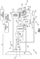
- FIG. 1 schematically illustrates an example propulsion system 20 including a core engine 22 that generates an exhaust gas flow 36.
- An evaporator 38 generates a steam flow 64 using water extracted from the gas flow 36 by a condenser assembly 40.
- a cooling system 45 is associated with the condenser 40 to maintain the temperature of extracted and stored water at a temperature within a predefined range. During some engine operating conditions, temperatures may not enable sufficient cooling to condense desired amounts of water from the gas flow 36.
- the cooling system 45 provides for cooling of stored water to reduced temperatures that improve water extraction from the gas flow 36.
- the core engine 22 includes a fan 24, a compressor section 26, a combustor section 28 and the turbine section 30.
- the fan 22 drives a bypass airflow 34 along a bypass flow path B, A core airflow 32 is drawn into the compressor section 26 and along a core flow path C where it is compressed and communicated to the combustor section 28.
- compressed core airflow 32 is mixed with a fuel flow 56 and ignited to generate the high energy combusted exhaust gas flow 36 that expands through the turbine section 30 where energy is extracted and utilized to drive the fan 24 and the compressor section 26.
- a fuel system 50 includes a fuel tank 52 and a pump 54 for generating the fuel flow 56 to the combustor section 28.
- the example fuel system 50 is configured to provide a hydrogen based fuel such as a liquid hydrogen (LH 2 ) and may include heat exchangers for boiling the fuel flow.
- a hydrogen based fuel such as a liquid hydrogen (LH 2 )
- LH 2 liquid hydrogen
- heat exchangers for boiling the fuel flow.
- hydrogen is disclosed by way of example, other non-carbon based fuels could be utilized and are within the contemplation of this disclosure.
- the disclosed features may also be beneficial in an engine configured to operate with traditional carbon based aviation fuels and/or biofuels, such as sustainable aviation fuels and the like.
- the example disclosed evaporator 38 receives a flow of water from a pump 48 that pressurizes water held within a water storage tank 46.
- the gas flow 36 heats the water in the evaporator 38 to generate the steam flow 64 that is injected into the core airflow 32.
- the steam flow 64 is injected into the combustor 28.
- the steam flow 64 may be injected in other locations and remain within the scope and contemplation of this disclosure.
- the steam flow 64 increases mass flow through the turbine section 30 and thereby increases engine power and efficiency.
- the increased power output from the injected steam 64 is due to increased mass flow through the turbine section 30 without a corresponding increase in work from the compressor section 26.
- the amount of water extracted within the condenser 40 is affected by a temperature differential between a cooling flow and the gas flow 36.
- bypass airflow 34 provides the cooling flow through the condenser 40.
- the temperature of the cooling flow may not provide a sufficient temperature differential to condense and extract a desired volume of water.
- water extracted during takeoff operating conditions may be much warmer than water extracted at during cruise conditions. For example, water extracted by the condenser 40 during takeoff operating conditions may be around 150 °F (65 °C), while water extracted during cruise conditions may be around 90 °F (32 °C).
- Water extracted during different operational periods will be at different temperatures.
- Water in the tank 46 extracted during cruise conditions may be at a much different temperature than the water extracted by the condenser at takeoff operating conditions.
- the water stored in the tank 46 that was extracted during cruise operation conditions may be below 100 °F (37 °C) even while the water being extracted during takeoff operating conditions by the condenser assembly is 150 °F (65 °C).
- water within the tank 56 and supplied to the evaporator 38 during takeoff operating conditions may be more than 30 °F (16 °C) colder than water being extracted by the condenser 40. Accordingly, stored water may be needed to accommodate different operating conditions and tailored to the various possible temperature differences between stored and extracted water.
- the example cooling system 45 provides for cooling of stored water that provides for a cooler temperature within the condenser assembly 40.
- the cooler temperatures within the condenser assembly 40 enable increased amounts of water extraction to accommodate less than optimal engine operating conditions.
- the cooling system 45 includes a chiller 44 that is in thermal communication with a cooling flow.
- the cooling flow is the bypass airflow 34.
- the cooling flow could be other coolants such as fuel or a refrigerant and remain within the scope and contemplation of this disclosure.
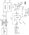
- Water flow between the chiller 44 and the water tank 46 is controlled by a valve 74.
- Water may flow directly from the water tank 46 to the chiller 44, or may be routed through a bypass passage 60 to the pump 48.
- a mix of water from the chiller 44 and the bypass passage 60 may be utilized to control a temperature of water provided to the evaporator 38.
- a single valve 74 is disclosed by way of example, additional valves or a system of conduits and valves could be utilized to control water flow and is within the contemplation and scope of this disclosure.
- the water tank 46 includes a water level sensor 104 that provides information indicative of a volume of water in the water tank 46.
- the water tank 46 further includes a drain 100 and a valve 102 that can be opened to enable water to be dumped if the volume of water in the tank exceeds a predefined capacity.
- a controller 66 receives input information 76 that is utilized to generate control instructions 78 to maintain the water temperature within a predefined range.
- the input information 76 is provided by a first temperature sensor 68 within the storage tank 46 and a second temperature sensor 70 near an outlet of the pump 48.
- a flow sensor 72 may, in some embodiments, provide information indicative of water flow extracted by the condenser assembly 40.
- the example flow sensor 72 is configured to communicate information to the controller 66 that is indicative of a flow rate of water into and out of the water storage tank 46.
- the water level sensor 104 provides information on the amount of water in the water tank 46.
- Other sensor systems and devices of the engine 20 may also be utilized to provide information indicative of water temperature and demand.
- the control instructions 78 may be used to control the valve 74 to bypass some portion of water flow through the bypass passage 60.
- the valve 102 may be used to assure that the volume of water does not exceed a predefined capacity.
- the valves 74 and 102 are shown by way of example, other control devices may be utilized to adjust an amount and cooling of water within the storage tank 46.
- the example controller 66 relates to a device and system for performing necessary computing or calculation operations of the cooling system 45.
- the controller 66 may be specially constructed for operation of the cooling system 45, or it may comprise at least a general-purpose computer selectively activated or reconfigured by software instructions.
- the controller 66 may further be part of full authority digital engine control (FADEC) or an electronic engine controller (EEC).
- FADEC full authority digital engine control
- EEC electronic engine controller
- the controller 66 may include any one or combination of volatile memory elements (e.g., random access memory (RAM, such as DRAM, SRAM, SDRAM, VRAM, etc.) and/or nonvolatile memory elements (e.g., ROM, hard drive, tape, CD-ROM, etc.).
- volatile memory elements e.g., random access memory (RAM, such as DRAM, SRAM, SDRAM, VRAM, etc.
- nonvolatile memory elements e.g., ROM, hard drive, tape, CD-ROM, etc.
- the software instructions may include one or more separate programs, each of which includes an ordered listing of executable instructions for implementing logical functions.
- the example controller 66 includes all devices that operate to communicate and to generate control instructions 78 utilizing to maintain a desired temperature of water within the water storage tank 46.
- a temperature (T1) of water within the storage tank 46 is communicated by the temperature sensor 68 to the controller 66.
- a temperature (T2) of water supplied to the evaporator 38 is communicated by the temperature sensor 70 to the controller 66.
- a flow rate from the flow sensor 72 is also communicated to the controller 66.
- the predefined temperature range for water within the storage tank 46 will vary depending on engine operating conditions, ambient conditions and any other factors that affect extraction of water from the gas flow 36. Moreover, the volume of water within the water storage tank 46 is measured by water level sensor 104 and may also be utilized as a basis for control of water temperature by dumping warmer water within the tank 46 to provide space for cooler water.
- the gas flow 36 is cooled in the condenser 40 by the bypass airflow 34 to condense water.
- the condensed water is separated from the gas flow 36 by a water separator 42 associated with the condenser 40.
- the extracted water is communicated to the storage tank 46. Water from the storage tank 46 is communicated to the evaporator 38 to generate the steam flow 64.
- Water from the storage tank 46 may be routed to the evaporator 38 through the chiller 44 or through a bypass passage 60 or a mixture of both.
- the chiller 44 is arranged in parallel with the condenser 40 such that both receive the cooling bypass airflow 34 separately.
- the example cooling system 45 is shown schematically as separate components. However, the example system 45 may be configured including other devise and locations. Moreover, the example devices of the cooling system 45 may be integrated into a single housing and remain within the contemplation and scope of this disclosure.
- a portion of water communicated to the chiller 44 is sent back to the storage tank 46 as a cooled water flow 62.
- a valve 74 is provided between the storage tank 46 and the chiller 44.
- the temperature within the water storage tank 46 may be controlled by controlling the flow rate and volume of water circulated back to the water storage tank 46.
- the controller 66 actuates the valve 74 to control water flow between the chiller 44 and the storage tank 46 based on the temperature T1, provided by the first temperature sensor 68. If the temperature within the storage tank 46 is outside of the predefined temperature range, the flow to and from the chiller 44 is adjusted until the temperature is within the predefined range. Adjustment of the temperature may include draining water through the drain 100 by control of the valve 102.
- Cooled water from the chiller 44 may be communicated to a heat exchanger 98 to cool another system 96.
- the system 96 may be an engine or aircraft system.
- the engine systems may include intercooling, and cooled cooling air systems along with any cooling systems associated with operation of the engine 20.
- the controller 66 receives information indicative of water temperature from temperature sensors 68 and 70 and information indicative of a volume of water from water level sensor 104.
- the controller 66 also receives information indicative of engine operating conditions and determines if the communicated temperature is within a predefined temperature range associated with a current engine operating condition (e.g., take-off, cruise, climb, descent, etc.).
- the predefined temperature range may be determined based on various engine operating parameters and conditions (e.g., engine temperature (e.g., turbine temperature, exhaust temperature, etc.), throttle or power lever position, fuel flow, etc.).
- Information may include demand during the current operating condition or may be preset parameters based on current conditions.
- the controller 66 may actuate the valve 74 to control the flow of water to the chiller 44. If the temperature of water at the storage tank 46 is greater than desired, the controller 66 may actuate the valve 74 to increase water flow sent through the chiller 44 and decrease water flow through the bypass passage 60. Cooled water flow 62 is sent back to the tank 46 until the temperatures are within the predefined temperature range.
- the controller 66 actuates the valve 74 to permit water to flow to the chiller as necessary to maintain the temperature within the predefined range. If the temperature of water within the tank 46 is below the predefined temperature range, the controller 66 may actuate the valve 74 to reduce the amount of water flowing through the chiller 74. The reduced flow of water through the chiller 44 will reduce the amount of chilled water circulates back to the tank 46 to increase water temperature.
- water provided by the condenser 40 is below about 150 °F (65 °C)
- water provided through the chiller 44 is below about 90 °F (32 °C)
- water within the tank 46 is regulated to be between just above freezing and about 90 °F (32 °C).
- valve 74 Although the flow of water through the valve 74 is disclosed by way of example as providing control of water temperature, other control devices could be utilized to adjust flows to provide for adjustment of the water temperature.
- the controller 66 may provide control for a volume of water stored in the tank 46.
- increased volumes of water may be recovered and stored in the tank 46.
- the increased volume of water within the tank may be maintained in anticipation of future operating conditions where water extraction is not as efficient.
- water obtained during cruise operating conditions is cooler than water extracted during takeoff conditions.
- the tank 46 therefore could be filled with cooler water during cruise conditions in anticipation of the next takeoff.
- the example controller 66 may increase the volume of water recovered and stored in the storage tank 46 in anticipation of operations at warmer conditions.
- Water stored in the tank 46 is disclosed as being extracted from the gas flow 36.
- the tank 46 may be filled during aircraft downtime prior to engine operation.
- the water provided by a ground based water system could be chilled to accommodate initial engine operation until water extraction is capable of meeting operational demands.
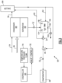
- the cooling system 55 includes a chiller 84 disposed in series with the condenser 40.
- the chiller 84 is located such that it receives the cooling bypass airflow 34 downstream from condenser 80 and water separator 82.
- the chiller 84 communicates a chilled water flow either to the evaporator 38 by way of the pump 48 or back to the water storage tank 46.
- the controller 66 uses information indicative of water condition 76 to generate instructions for operation of the valve 74.
- the example valve 74 is configured to proportion flow between the chiller 84 and the bypass passage 60 to maintain the water temperature within the water storage tank 46 within a predefined range.
- the controller 66 may also control the level of water within the tank 46 by draining water through the drain 100 by operation of the valve 102.
- turbofan turbine engine depicts a turbofan turbine engine
- concepts described herein are not limited to use with turbofans as the teachings may be applied to other types of turbine engines. Additionally, the features of this disclosure may be applied to other engine configurations utilized to generate shaft power.
- the example engine embodiments enable increased water extraction by maintaining stored water temperatures within predefined ranges determined to generate desired amounts of water flow for engine operating conditions.
Landscapes
- Engineering & Computer Science (AREA)
- Chemical & Material Sciences (AREA)
- Combustion & Propulsion (AREA)
- Mechanical Engineering (AREA)
- General Engineering & Computer Science (AREA)
- Engine Equipment That Uses Special Cycles (AREA)
Applications Claiming Priority (1)
| Application Number | Priority Date | Filing Date | Title |
|---|---|---|---|
| US18/304,524 US12031485B1 (en) | 2023-04-21 | 2023-04-21 | Water storage precooling and water cycle chiller |
Publications (1)
| Publication Number | Publication Date |
|---|---|
| EP4450787A1 true EP4450787A1 (de) | 2024-10-23 |
Family
ID=90826242
Family Applications (1)
| Application Number | Title | Priority Date | Filing Date |
|---|---|---|---|
| EP24171733.9A Pending EP4450787A1 (de) | 2023-04-21 | 2024-04-22 | Wasserspeicher-vorkühlung und wasserkreislaufkühler |
Country Status (2)
| Country | Link |
|---|---|
| US (1) | US12031485B1 (de) |
| EP (1) | EP4450787A1 (de) |
Families Citing this family (3)
| Publication number | Priority date | Publication date | Assignee | Title |
|---|---|---|---|---|
| US12421895B2 (en) * | 2024-02-01 | 2025-09-23 | General Electric Company | Turbine engine including a condenser system |
| US20250369393A1 (en) * | 2024-05-30 | 2025-12-04 | Rtx Corporation | Axial flow angled condenser arrangement for an aircraft propulsion system |
| US12331687B1 (en) * | 2024-08-02 | 2025-06-17 | Rtx Corporation | Cryogenic fuel semi-closed injection cooled bottoming cycle |
Citations (4)
| Publication number | Priority date | Publication date | Assignee | Title |
|---|---|---|---|---|
| US6286301B1 (en) * | 1995-12-28 | 2001-09-11 | Hitachi, Ltd. | Gas turbine, combined cycle plant and compressor |
| US20150033751A1 (en) * | 2013-07-31 | 2015-02-05 | General Electric Company | System and method for a water injection system |
| US20210207500A1 (en) * | 2018-05-22 | 2021-07-08 | MTU Aero Engines AG | Exhaust-gas treatment device, aircraft propulsion system, and method for treating an exhaust-gas stream |
| US20230035231A1 (en) * | 2021-07-28 | 2023-02-02 | Pratt & Whitney Canada Corp. | Aircraft engine with hydrogen fuel system |
Family Cites Families (10)
| Publication number | Priority date | Publication date | Assignee | Title |
|---|---|---|---|---|
| US2447696A (en) * | 1944-12-13 | 1948-08-24 | Fairey Aviat Co Ltd | Combustion gas and steam turbine arrangement |
| US4509324A (en) * | 1983-05-09 | 1985-04-09 | Urbach Herman B | Direct open loop Rankine engine system and method of operating same |
| DE102021201629A1 (de) | 2020-08-05 | 2022-02-10 | MTU Aero Engines AG | Abgasbehandlungsvorrichtung für ein flugtriebwerk |
| WO2022232828A1 (en) * | 2021-04-30 | 2022-11-03 | University Of Florida Research Foundation, Inc. | Semi-closed cycle aero engine with contrail suppression |
| US11635022B1 (en) * | 2022-02-11 | 2023-04-25 | Raytheon Technologies Corporation | Reducing contrails from an aircraft powerplant |
| US11920515B2 (en) * | 2022-05-13 | 2024-03-05 | Rtx Corporation | Condenser for hydrogen steam injected turbine engine |
| US12098645B2 (en) * | 2022-05-19 | 2024-09-24 | Rtx Corporation | Superheated steam injection turbine engine |
| US11933217B2 (en) * | 2022-07-21 | 2024-03-19 | Rtx Corporation | Water condition monitoring for hydrogen steam injected and inter-cooled turbine engine |
| US20240026816A1 (en) * | 2022-07-22 | 2024-01-25 | Raytheon Technologies Corporation | Hydrogen-oxygen gas turbine engine |
| US11920526B1 (en) * | 2022-08-12 | 2024-03-05 | Rtx Corporation | Inter-cooled preheat of steam injected turbine engine |
-
2023
- 2023-04-21 US US18/304,524 patent/US12031485B1/en active Active
-
2024
- 2024-04-22 EP EP24171733.9A patent/EP4450787A1/de active Pending
Patent Citations (4)
| Publication number | Priority date | Publication date | Assignee | Title |
|---|---|---|---|---|
| US6286301B1 (en) * | 1995-12-28 | 2001-09-11 | Hitachi, Ltd. | Gas turbine, combined cycle plant and compressor |
| US20150033751A1 (en) * | 2013-07-31 | 2015-02-05 | General Electric Company | System and method for a water injection system |
| US20210207500A1 (en) * | 2018-05-22 | 2021-07-08 | MTU Aero Engines AG | Exhaust-gas treatment device, aircraft propulsion system, and method for treating an exhaust-gas stream |
| US20230035231A1 (en) * | 2021-07-28 | 2023-02-02 | Pratt & Whitney Canada Corp. | Aircraft engine with hydrogen fuel system |
Also Published As
| Publication number | Publication date |
|---|---|
| US12031485B1 (en) | 2024-07-09 |
Similar Documents
| Publication | Publication Date | Title |
|---|---|---|
| EP4450787A1 (de) | Wasserspeicher-vorkühlung und wasserkreislaufkühler | |
| CN104813004B (zh) | 包括恒温膨胀阀的双重燃料航空器系统 | |
| CN104884766B (zh) | 涡轮发动机组件及双燃料飞行器系统 | |
| US20230243308A1 (en) | Installation for heating a cryogenic fuel | |
| EP2829706B1 (de) | Zapfluftsysteme zur Verwendung mit Flugzeugen und zugehörige Verfahren | |
| EP4455466A1 (de) | Anordnung zum schutz der abgasleitungs mittels eines nachkühlers | |
| EP4414536A1 (de) | Dampfturbinenbypass für einen turbinenmotor mit dampfeinspritzung und erhöhter wasserwärmeabsorptionskapazität | |
| CN105026268A (zh) | 用于飞行器发动机的低温燃料的能量有效且受控的汽化 | |
| EP4187070B1 (de) | Gasturbine | |
| US10029799B2 (en) | Air conditioning method and system for aircraft | |
| EP4517067A1 (de) | Zwischenkühlung durch kondensation eines teilabgasstroms | |
| US20240384907A1 (en) | Vapor cycle system for cooling components and associated method | |
| US20180156508A1 (en) | Expendable driven heat pump cycles | |
| EP4450786A2 (de) | Bypass-wärmetauscherkonfiguration zur umleitung eines kernstroms | |
| US20240360788A1 (en) | Partial exhaust condensation with cryogenic assisted bottoming cycle | |
| EP4520934A1 (de) | Partielle abgaskondensation mit inverser brayton-regelung | |
| US12529333B2 (en) | Partial exhaust condensation with cryogenic assisted bottoming cycle | |
| EP4513018B1 (de) | Brennstoffsystem für gasturbinenmotor | |
| EP4647591A1 (de) | Flugzeugkraftstoffsystem und -verfahren | |
| EP4647592A1 (de) | Flugzeugkraftstoffsystem und -verfahren | |
| EP4686813A1 (de) | Kryogenes bottoming-zyklus-steuersystem | |
| EP4686816A2 (de) | Kryogener bottoming-kreislauf mit variabler fluidmischung | |
| EP4613993A1 (de) | Wasserstoffbetriebener gasturbinenmotor | |
| US20250283429A1 (en) | Hydrogen fuelled gas turbine engine | |
| EP4678887A1 (de) | Teilkondensation von abgasen mit kryogenem unterstütztem bottoming-zyklus |
Legal Events
| Date | Code | Title | Description |
|---|---|---|---|
| PUAI | Public reference made under article 153(3) epc to a published international application that has entered the european phase |
Free format text: ORIGINAL CODE: 0009012 |
|
| STAA | Information on the status of an ep patent application or granted ep patent |
Free format text: STATUS: THE APPLICATION HAS BEEN PUBLISHED |
|
| AK | Designated contracting states |
Kind code of ref document: A1 Designated state(s): AL AT BE BG CH CY CZ DE DK EE ES FI FR GB GR HR HU IE IS IT LI LT LU LV MC ME MK MT NL NO PL PT RO RS SE SI SK SM TR |
|
| STAA | Information on the status of an ep patent application or granted ep patent |
Free format text: STATUS: REQUEST FOR EXAMINATION WAS MADE |
|
| 17P | Request for examination filed |
Effective date: 20250423 |