EP4450786A2 - Bypass-wärmetauscherkonfiguration zur umleitung eines kernstroms - Google Patents
Bypass-wärmetauscherkonfiguration zur umleitung eines kernstroms Download PDFInfo
- Publication number
- EP4450786A2 EP4450786A2 EP24170754.6A EP24170754A EP4450786A2 EP 4450786 A2 EP4450786 A2 EP 4450786A2 EP 24170754 A EP24170754 A EP 24170754A EP 4450786 A2 EP4450786 A2 EP 4450786A2
- Authority
- EP
- European Patent Office
- Prior art keywords
- exhaust gas
- gas flow
- condenser
- flow
- temperature
- Prior art date
- Legal status (The legal status is an assumption and is not a legal conclusion. Google has not performed a legal analysis and makes no representation as to the accuracy of the status listed.)
- Pending
Links
Images


Classifications
-
- F—MECHANICAL ENGINEERING; LIGHTING; HEATING; WEAPONS; BLASTING
- F02—COMBUSTION ENGINES; HOT-GAS OR COMBUSTION-PRODUCT ENGINE PLANTS
- F02C—GAS-TURBINE PLANTS; AIR INTAKES FOR JET-PROPULSION PLANTS; CONTROLLING FUEL SUPPLY IN AIR-BREATHING JET-PROPULSION PLANTS
- F02C3/00—Gas-turbine plants characterised by the use of combustion products as the working fluid
- F02C3/20—Gas-turbine plants characterised by the use of combustion products as the working fluid using a special fuel, oxidant, or dilution fluid to generate the combustion products
- F02C3/30—Adding water, steam or other fluids for influencing combustion, e.g. to obtain cleaner exhaust gases
-
- F—MECHANICAL ENGINEERING; LIGHTING; HEATING; WEAPONS; BLASTING
- F02—COMBUSTION ENGINES; HOT-GAS OR COMBUSTION-PRODUCT ENGINE PLANTS
- F02C—GAS-TURBINE PLANTS; AIR INTAKES FOR JET-PROPULSION PLANTS; CONTROLLING FUEL SUPPLY IN AIR-BREATHING JET-PROPULSION PLANTS
- F02C3/00—Gas-turbine plants characterised by the use of combustion products as the working fluid
- F02C3/34—Gas-turbine plants characterised by the use of combustion products as the working fluid with recycling of part of the working fluid, i.e. semi-closed cycles with combustion products in the closed part of the cycle
-
- F—MECHANICAL ENGINEERING; LIGHTING; HEATING; WEAPONS; BLASTING
- F02—COMBUSTION ENGINES; HOT-GAS OR COMBUSTION-PRODUCT ENGINE PLANTS
- F02C—GAS-TURBINE PLANTS; AIR INTAKES FOR JET-PROPULSION PLANTS; CONTROLLING FUEL SUPPLY IN AIR-BREATHING JET-PROPULSION PLANTS
- F02C6/00—Plural gas-turbine plants; Combinations of gas-turbine plants with other apparatus; Adaptations of gas-turbine plants for special use
- F02C6/18—Plural gas-turbine plants; Combinations of gas-turbine plants with other apparatus; Adaptations of gas-turbine plants for special use using the waste heat of gas-turbine plants outside the plants themselves, e.g. gas-turbine power heat plants
-
- F—MECHANICAL ENGINEERING; LIGHTING; HEATING; WEAPONS; BLASTING
- F02—COMBUSTION ENGINES; HOT-GAS OR COMBUSTION-PRODUCT ENGINE PLANTS
- F02C—GAS-TURBINE PLANTS; AIR INTAKES FOR JET-PROPULSION PLANTS; CONTROLLING FUEL SUPPLY IN AIR-BREATHING JET-PROPULSION PLANTS
- F02C6/00—Plural gas-turbine plants; Combinations of gas-turbine plants with other apparatus; Adaptations of gas-turbine plants for special use
- F02C6/20—Adaptations of gas-turbine plants for driving vehicles
-
- F—MECHANICAL ENGINEERING; LIGHTING; HEATING; WEAPONS; BLASTING
- F02—COMBUSTION ENGINES; HOT-GAS OR COMBUSTION-PRODUCT ENGINE PLANTS
- F02C—GAS-TURBINE PLANTS; AIR INTAKES FOR JET-PROPULSION PLANTS; CONTROLLING FUEL SUPPLY IN AIR-BREATHING JET-PROPULSION PLANTS
- F02C7/00—Features, components parts, details or accessories, not provided for in, or of interest apart form groups F02C1/00 - F02C6/00; Air intakes for jet-propulsion plants
- F02C7/12—Cooling of plants
- F02C7/14—Cooling of plants of fluids in the plant, e.g. lubricant or fuel
- F02C7/141—Cooling of plants of fluids in the plant, e.g. lubricant or fuel of working fluid
- F02C7/143—Cooling of plants of fluids in the plant, e.g. lubricant or fuel of working fluid before or between the compressor stages
- F02C7/1435—Cooling of plants of fluids in the plant, e.g. lubricant or fuel of working fluid before or between the compressor stages by water injection
-
- F—MECHANICAL ENGINEERING; LIGHTING; HEATING; WEAPONS; BLASTING
- F02—COMBUSTION ENGINES; HOT-GAS OR COMBUSTION-PRODUCT ENGINE PLANTS
- F02C—GAS-TURBINE PLANTS; AIR INTAKES FOR JET-PROPULSION PLANTS; CONTROLLING FUEL SUPPLY IN AIR-BREATHING JET-PROPULSION PLANTS
- F02C9/00—Controlling gas-turbine plants; Controlling fuel supply in air- breathing jet-propulsion plants
- F02C9/16—Control of working fluid flow
- F02C9/18—Control of working fluid flow by bleeding, bypassing or acting on variable working fluid interconnections between turbines or compressors or their stages
-
- F—MECHANICAL ENGINEERING; LIGHTING; HEATING; WEAPONS; BLASTING
- F05—INDEXING SCHEMES RELATING TO ENGINES OR PUMPS IN VARIOUS SUBCLASSES OF CLASSES F01-F04
- F05D—INDEXING SCHEME FOR ASPECTS RELATING TO NON-POSITIVE-DISPLACEMENT MACHINES OR ENGINES, GAS-TURBINES OR JET-PROPULSION PLANTS
- F05D2260/00—Function
- F05D2260/20—Heat transfer, e.g. cooling
- F05D2260/212—Heat transfer, e.g. cooling by water injection
-
- F—MECHANICAL ENGINEERING; LIGHTING; HEATING; WEAPONS; BLASTING
- F05—INDEXING SCHEMES RELATING TO ENGINES OR PUMPS IN VARIOUS SUBCLASSES OF CLASSES F01-F04
- F05D—INDEXING SCHEME FOR ASPECTS RELATING TO NON-POSITIVE-DISPLACEMENT MACHINES OR ENGINES, GAS-TURBINES OR JET-PROPULSION PLANTS
- F05D2260/00—Function
- F05D2260/20—Heat transfer, e.g. cooling
- F05D2260/213—Heat transfer, e.g. cooling by the provision of a heat exchanger within the cooling circuit
Definitions
- the present invention relates generally to an aircraft propulsion system that includes a steam generation system transforming recovered water into a steam flow injected into a core flow.
- Turbine engines compress incoming core airflow, mix the compressed airflow with fuel that is ignited in a combustor to generate a high energy exhaust gas flow. Some energy in the high energy exhaust flow is recovered as it is expanded through a turbine section. Steam injection can provide improved propulsive efficiencies. Water recovered from the high energy exhaust may be transformed into steam using the remaining thermal energy from the exhaust gas flow. Water recovery and steam generation utilize heat exchangers exposed to the high energy exhaust gas flows. Some engine operating conditions can result in exhaust gas flow temperatures that approach material and operation limits of the heat exchangers.
- a turbine engine assembly includes, a compressor section where an inlet airflow is compressed, a combustor section where the compressed inlet airflow is mixed with fuel and ignited to generate an exhaust gas flow, a turbine section through which the exhaust gas flow expands to generate a mechanical power output, at least one heat exchanger that is in thermal communication with the exhaust gas flow, and a bypass passage that is configured to selectively route at least a portion of the exhaust gas flow around the at least one heat exchanger in response to a predefined engine operating condition.
- the at least one heat exchanger includes at least one of a condenser where water is extracted from the exhaust gas flow and an evaporator system.
- the evaporator is configured to use thermal energy from the exhaust gas flow to generate a steam flow from at least a portion of water that is extracted by the condenser for injection into a core flow path.
- the turbine engine includes a flow control device that is operated by a controller.
- the controller is configured to control an amount of available water and to control the flow control device to selectively direct the exhaust gas flow into the bypass passage based, at least in part, on information indicative of an amount of available water.
- the turbine engine includes a flow control device that is operated by a controller for selectively directing the exhaust gas flow into the bypass passage and a sensor assembly that communicates information indicative of a temperature of the at least one heat exchanger.
- the predefined engine operating condition is a temperature and the controller is programmed to operate the flow control device to route exhaust gas flow into the bypass passage that is responsive to a sensed temperature of the at least one heat exchanger that exceeds a predefined threshold temperature.
- the controller is programmed to operate the flow control device to close the bypass passage such that the exhaust gas flow is directed through the at least one heat exchanger in response to the sensed temperature returning below the predefined threshold temperature.
- the bypass passage includes an outlet to exhaust bypassed exhaust gas flow to the ambient environment.
- An aircraft propulsion system includes, a core engine section that generates an exhaust gas flow, a propulsor that is driven by the core engine, a condenser where water is extracted from the exhaust gas flow, an evaporator system where thermal energy from the exhaust gas flow is utilized to generate a steam flow from at least a portion of water that is extracted by the condenser for injection into the core engine, and a bypass passage that is configured to selectively route at least a portion of the exhaust gas flow around at least one of the evaporator and the condenser in response to a predefined engine operating condition.
- the aircraft propulsion system includes a flow control device that is operated by a controller for selectively directing the exhaust gas flow into the bypass passage.
- the aircraft propulsion system includes a sensor assembly that communicates information indicative of a temperature of at least one of the condenser or the evaporator system to the controller.
- the predefined engine operating condition is a temperature and the controller is programmed to operate the flow control device to route exhaust gas flow into the bypass passage that is responsive to a sensed temperature of at least one of the condenser or the evaporator system that exceeds a predefined threshold temperature.
- the controller is programmed to operate the flow control device to close the bypass passage such that the exhaust gas flow is directed through the evaporator system and the condenser in response to the sensed temperature being below the predefined threshold temperature.
- a method of operating an aircraft propulsion system includes, generating an exhaust gas flow, measuring an engine operating parameter that is indicative of a temperature of at least one of a condenser where water is extracted from the exhaust gas flow and an evaporator where thermal energy from the exhaust gas flow is utilized to generate a steam flow from at least a portion of water that is extracted by the condenser, and selectively routing at least, a portion of the exhaust gas flow around one or both of the condenser and the evaporator in response to the measured engine operating parameter being indicative of a temperature exceeding a predefined threshold.
- the method includes selectively operating a flow control device to selectively direct the exhaust gas flow into a bypass passage.
- the method includes selectively operating the flow control device to direct the exhaust gas flow through the evaporator system and the condenser in response to the measured engine operating parameter being indicative of the temperature being below the predefined threshold temperature.
- the method further includes directing exhaust gas flow through the evaporator and the condenser in response to a predefined amount of water being communicated to the evaporator.
- the method includes selectively routing at least a portion of the exhaust gas flow around one or both of the condenser and the evaporator includes routing exhaust gas flow around the condenser.
- the method includes selectively routing at least a portion of the exhaust gas flow around one or both of the condenser and the evaporator includes routing the exhaust gas flow around both the condenser and the evaporator.
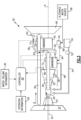
- Figure 1 schematically illustrates an example propulsion system 20 that includes a bypass passage 58 for routing exhaust gas flow around heat exchangers of a condenser 40 and an evaporator system 42.
- the bypass passage 58 provides for rerouting of an exhaust gas flow 38 during engine operating conditions where temperatures exceed predefined temperature limits of the condenser 40 and/or the evaporator system 42.
- the engine 20 includes a fan section 22, a compressor section 24, a combustor section 26 and the turbine section 28 disposed along an engine longitudinal axis A.
- the example turbine section 28 includes a high pressure turbine (HPT) 30 and a low pressure turbine (LPT) 32.
- the fan section 22 drives inlet airflow 34 along a bypass flow path B, while the compressor section 24 draws air in along a core flow path C.
- the inlet airflow 34 is compressed and communicated to a combustor section 26 where the compressed core airflow 34 is mixed with a fuel flow 54 and ignited to generate the high energy combusted exhaust gas flow 38.
- the exhaust gas flow 38 expands through the turbine section 28 where energy is extracted and utilized to drive the fan section 22 and the compressor section 24.
- a fuel system 55 including at least a fuel tank 50 and a fuel pump 52 provide a fuel flow 54 to the combustor 26.
- the example fuel system 55 is configured to provide a hydrogen based fuel such as a liquid hydrogen (LH 2 ).
- a hydrogen based fuel such as a liquid hydrogen (LH 2 ).
- LH 2 liquid hydrogen
- hydrogen is disclosed by way of example, other non-carbon based fuels could be utilized and are within the contemplation of this disclosure.
- the disclosed features may also be beneficial in an engine configured to operate with traditional carbon-based fuels and/or sustainable aviation fuels.
- An evaporator system 42 and condenser 40 are disposed downstream of the turbine section 28 and receive the exhaust gas flow 38.
- the example evaporator system 42 utilizes thermal energy from the exhaust gas flow 38 to generate a steam flow 48 from a water flow 46 extracted by the condenser 40.
- the condenser 40 cools the exhaust gas flow 38 to extract water that is gathered in a tank 44 and pressurized by a pump 68 for communication of the water flow 46 to the evaporator system 42.
- a bypass flow 36 is utilized to cool the exhaust gas flow 38 in the condenser 40.
- Other cold sink flows and systems may be utilized to cool the exhaust gas flow 38 within the condenser 40 and are within the contemplation and scope of this disclosure.
- the steam flow 48 from the evaporator is communicated to the combustor 26 and combined with the exhaust gas flow 38 to increase mass flow through the turbine section 28 and thereby increases engine power and efficiency.
- the engine 20 has an increased power output from the injected steam 48 due to an increasing mass flow through the turbine section 28 without a corresponding increase in work from the compressor section 24.
- the steam flow 48 is shown as being injected into the combustor 26, the steam flow 48 may be injected at other locations along the core flow path C.
- the condenser 40 and the evaporator system 42 are heat exchangers that are exposed to the high temperatures of the high energy exhaust gas flow 38. During typical engine operating conditions, the temperatures at each of the condenser and evaporator system 42 are within defined operating ranges. However, engine operating conditions at higher ambient temperatures or different operating settings may increase temperatures of the gas flow 38 and thereby the condenser 40 and evaporator system 42. Such higher temperature may approach predefined operating limits of the condenser 40 and the evaporator system 42.
- the example engine 20 includes a bypass passage 58 for selectively routing at least a portion of the exhaust gas flow 38 around the condenser 40 and evaporator system 42. In one example embodiment, the exhaust gas flow 38 is routed to an outlet 64 and through the nozzle 66.
- heat exchangers are disclosed by way of example as the condenser 40 and the evaporator system 42, other heat exchangers that are in thermal communication with the exhaust gas flow may benefit from the selective bypass of the exhaust gas flow and are within the contemplation of this disclosure.
- heat exchangers utilized for capture of waste heat in a bottoming energy recovery cycle may benefit from this disclosure.
- the evaporator system 42 may include additional heat exchangers upstream of the bypass passage 58.
- a superheater may be provided to further heat the steam flow 48 upstream of the bypass passage 58.
- a flow control device 56 is disposed after the turbine section 28 and before the evaporator system 42.
- the flow control device 56 is configured to direct the exhaust gas flow 38 through an inlet 62 and the bypass passage 58 to the outlet 64, bypassing the condenser 40 and evaporator system 42. Rerouting of the exhaust gas flow 38 prevents exposure to gas flows above predefined temperatures.
- the example flow control device 56 is shown schematically and may include any ducting, actuators, and structure necessary for routing flow into the bypass passage 58. Moreover, the example flow control device 56 may be a variable device for routing only a portion of the exhaust flow 38 into the bypass passage 58.
- a controller 60 is provided and programmed to operate the flow control device 56 based on information from at least one sensor assembly.
- a first sensor assembly 70 provides information indicative of a temperature at the condenser 40.
- a second sensor assembly 72 is associated with the evaporator system 42.
- the flow control device 56 is operable by the controller 60 to selectively divert the exhaust gas flow 38 through the bypass passage 58 based on sensed temperatures in at least one of the condenser 40 and the evaporator system 42 exceeding a predefined threshold temperature.
- the threshold temperature is determined based on the material and structural capability of the condenser 40 and evaporator system 42.
- the controller 60 may also be programmed to control an amount of available water either stored in the storage tank 44 or generated by the condenser 40.
- the controller 60 is programed to operate the flow control device 56 to selectively direct the exhaust gas flow 38 into the bypass passage 58 based, at least in part, on information indicative of a volume/amount of available water, indicated schematically at 90.
- Information indicative of the volume of water 90 may be obtained from sensors located within the tank 44 or through the use of other engine information.
- the controller 60 may be programmed to obtain additional water from an alternate water source 86 when the available water is below a predefined threshold amount.
- the example engine operating condition is a temperature at the condenser 40 and/or the evaporator system 42.
- the operating condition may include any one or a combination of pressure, temperature, power settings, shaft speed and any other one or combination of monitored engine operating conditions.
- the controller 60 is programmed to operate the flow control device 56 based on operation information, indicated schematically at 84, provided to the controller 60.
- the operation information 84 can include monitored engine parameters such as shaft speeds, pressures, and temperatures in other locations of the engine 20.
- the operation information 84 may include any other operational information gathered during engine operation, including, for example, ambient temperature and altitude.
- the example controller 60 is a device and system for performing necessary computing or calculation operations.
- the example controller 60 may be specially constructed for this purpose, or it may comprise at least a general-purpose computer selectively activated or reconfigured by a computer program stored in the computer.
- the controller 60 may be a dedicated controller, or part of an engine controller or aircraft controller.
- the controller 60 may include a computer program directing operation. Such a computer program and also data required for its execution may be stored in a computer readable storage medium, such as, but is not limited to, any type of disk, optical disks, CD-ROMs, magnetic-optical disks, read-only memories (ROMs), random access memories (RAMS), EPROMs, EEPROMs, magnetic or optical cards, application specific integrated circuits (ASICs), or any type of media suitable for storing electronic instructions, and each coupled to a computer system bus. Furthermore, the computer system may include a single processor or architectures employing multiple processors designed for increased computing capability.
- the example engine 20 is shown in an operating condition where all of the exhaust gas flow 38 is routed through the bypass passage 58.
- the flow control device 56 is opened to direct the exhaust gas flow 38 through the inlet 62 and into the bypass passage 58.
- the bypassed exhaust gas flow 74 is exhausted through the outlet 64 and through the nozzle 66 into the ambient environment.
- a temperature sensor assembly 88 is provided to obtain information indicative of a temperature of the exhaust gas flow 38 near the flow control device 56.
- the example sensor assembly 88 is shown schematically and may not be disposed directly within the exhaust flow 38, but instead associated with a structure that provides for obtaining information that is indictive of the gas flow 38. Other locations for the sensor assembly and information can be utilized to determine when the exhaust gas flow 38 is at a temperature that is within an acceptable range to close the flow control device 56 and reengage gas flows through the evaporator system 42 and the condenser 40.
- an alternate water source 86 may be in communication with the water tank 44 to provide a quantity of water needed to continue or restart steam generation.
- the alternate water source 86 may be a storage tank or water producing device onboard the aircraft, such as, for example, a fuel cell.
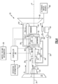
- another example engine assembly 25 is shown by way of example and includes the flow control device 56 disposed before the condenser 40. Accordingly, in this example embodiment, the gas flow 38 is permitted to pass through the evaporator system 42 and is diverted before it reaches the condenser 40. Because the condenser 40 is downstream of the evaporator system 42, the exhaust gas flow 38 at the condenser 40 is typically much cooler than at the evaporator system 42. Additionally, the condenser 40 is in thermal communication with the bypass flow 36 and thereby cooler. Accordingly, the condenser 40 may be constructed of materials with a lesser temperature capability as compared to the evaporator system 42. Therefore, the flow control device 56 is arranged to protect the condenser 40 from high temperatures by diverting flow into the bypass passage 58.
- the alternate water source 86 may continue supplying water to the tank 44 to enable continued production of the steam flow 48 in the evaporator system 42.
- the engine 35 includes a first flow control device 76 and a second flow control device 78.
- the first flow control device 76 is disposed before the evaporator system 42 and the second flow control device is disposed before the condenser 40.
- Each of the flow control devices includes an inlet 80, 82 for directing gas flow 38 into the bypass passage 58.
- the two flow control devices 76, 78 provide for tailoring of bypass flow to engine operating conditions. In some engine operating conditions, only the second flow control device 78 is actuated to divert gas flow around the condenser 40. In other engine operating conditions, the first flow control device 76 is actuated to divert gas flow 38 around both the evaporator system 42 and the condenser 40.
- the first flow control device 76 is closed and gas flow 84 through the evaporator system 42 is diverted into the bypass passage 58 at the second flow control device 78.
- the evaporator system 42 may continue generating the steam flow 48 with water from the alternate water source 86. Exhaust gases are bypassed around the condenser 40 until cooled to a temperature compatible with condenser operation 40. The compatible temperature may be based on material threshold of the condenser 40 or other operating requirements.
- the inclusion of the first and second flow control devices 76, 78 provides for the ability of the controller 60 to tailor operation to current engine and aircraft operating conditions.
- the example engine embodiments provide protection of the evaporator and condenser from temperatures that exceed predefined operating temperature limits of the exhaust gas flow with a bypass passage configured to selectively route at least a portion of the exhaust gas flow around at least one of the evaporator and the condenser.
Landscapes
- Engineering & Computer Science (AREA)
- Chemical & Material Sciences (AREA)
- Combustion & Propulsion (AREA)
- Mechanical Engineering (AREA)
- General Engineering & Computer Science (AREA)
- Physics & Mathematics (AREA)
- Fluid Mechanics (AREA)
- Life Sciences & Earth Sciences (AREA)
- Sustainable Development (AREA)
- Engine Equipment That Uses Special Cycles (AREA)
- Heat-Exchange Devices With Radiators And Conduit Assemblies (AREA)
Applications Claiming Priority (1)
| Application Number | Priority Date | Filing Date | Title |
|---|---|---|---|
| US18/302,081 US12065964B1 (en) | 2023-04-18 | 2023-04-18 | Bypass heat exchanger configuration to reroute core flow |
Publications (2)
| Publication Number | Publication Date |
|---|---|
| EP4450786A2 true EP4450786A2 (de) | 2024-10-23 |
| EP4450786A3 EP4450786A3 (de) | 2025-03-05 |
Family
ID=90789181
Family Applications (1)
| Application Number | Title | Priority Date | Filing Date |
|---|---|---|---|
| EP24170754.6A Pending EP4450786A3 (de) | 2023-04-18 | 2024-04-17 | Bypass-wärmetauscherkonfiguration zur umleitung eines kernstroms |
Country Status (2)
| Country | Link |
|---|---|
| US (1) | US12065964B1 (de) |
| EP (1) | EP4450786A3 (de) |
Families Citing this family (3)
| Publication number | Priority date | Publication date | Assignee | Title |
|---|---|---|---|---|
| US12421895B2 (en) * | 2024-02-01 | 2025-09-23 | General Electric Company | Turbine engine including a condenser system |
| US12454926B1 (en) * | 2024-04-30 | 2025-10-28 | Pratt & Whitney Canada Corp. | Exhaust nozzle assembly for an aircraft propulsion system |
| US12331687B1 (en) * | 2024-08-02 | 2025-06-17 | Rtx Corporation | Cryogenic fuel semi-closed injection cooled bottoming cycle |
Family Cites Families (15)
| Publication number | Priority date | Publication date | Assignee | Title |
|---|---|---|---|---|
| US3799249A (en) * | 1969-11-26 | 1974-03-26 | Air Reduction Inc | Hot gas heat exchanger |
| CA2409700C (en) * | 2000-05-12 | 2010-02-09 | Clean Energy Systems, Inc. | Semi-closed brayton cycle gas turbine power systems |
| JP3886492B2 (ja) * | 2001-12-03 | 2007-02-28 | 東京電力株式会社 | 排熱回収システム |
| JP4241239B2 (ja) * | 2003-07-07 | 2009-03-18 | 株式会社Ihi | ガスタービン |
| CH706152A1 (de) * | 2012-02-29 | 2013-08-30 | Alstom Technology Ltd | Gasturbinenanlage mit einer Abwärmekesselanordnung mit Abgasrückführung. |
| GB2530896B (en) * | 2013-06-20 | 2016-11-02 | Boustead Int Heaters Ltd | Improvements in waste heat recovery units |
| US20160369695A1 (en) * | 2015-06-16 | 2016-12-22 | United Technologies Corporation | Temperature-modulated recuperated gas turbine engine |
| US20180080375A1 (en) * | 2016-09-21 | 2018-03-22 | Jack Yajie Chen | Steam Micro Turbine Engine |
| GB2573131A (en) * | 2018-04-25 | 2019-10-30 | Hieta Tech Limited | Combined heat and power system |
| DE102018208026A1 (de) * | 2018-05-22 | 2019-11-28 | MTU Aero Engines AG | Abgasbehandlungsvorrichtung, Flugzeugantriebssystem und Verfahren zum Behandeln eines Abgasstromes |
| JP7063971B2 (ja) * | 2019-12-18 | 2022-05-09 | 三菱重工業株式会社 | 加圧空気供給システム、及び、加圧空気供給システムの起動方法 |
| DE102021201629A1 (de) * | 2020-08-05 | 2022-02-10 | MTU Aero Engines AG | Abgasbehandlungsvorrichtung für ein flugtriebwerk |
| US11635022B1 (en) * | 2022-02-11 | 2023-04-25 | Raytheon Technologies Corporation | Reducing contrails from an aircraft powerplant |
| US11753993B1 (en) * | 2022-02-11 | 2023-09-12 | Raytheon Technologies Corporation | Turbine engine with mass rejection |
| US11603798B1 (en) * | 2022-02-11 | 2023-03-14 | Raytheon Technologies Corporation | Cryogenically assisted exhaust condensation |
-
2023
- 2023-04-18 US US18/302,081 patent/US12065964B1/en active Active
-
2024
- 2024-04-17 EP EP24170754.6A patent/EP4450786A3/de active Pending
Also Published As
| Publication number | Publication date |
|---|---|
| US12065964B1 (en) | 2024-08-20 |
| EP4450786A3 (de) | 2025-03-05 |
Similar Documents
| Publication | Publication Date | Title |
|---|---|---|
| EP4450786A2 (de) | Bypass-wärmetauscherkonfiguration zur umleitung eines kernstroms | |
| US11808209B1 (en) | Aftercooler exhaust duct protection | |
| EP3623604B1 (de) | Hybrider expansionszyklus mit vorverdichtungskühlung und turbogenerator | |
| EP3904658B1 (de) | Gasturbinenmotoren mit kryogenen kraftstoffsystemen | |
| CN109812338B (zh) | 热管理系统 | |
| CN110529256B (zh) | 用于燃气涡轮发动机组件的空气循环组件 | |
| CN114278402B (zh) | 具有冷却的冷却空气换热器系统的热力发动机 | |
| EP0903484B1 (de) | Gasturbinenanlage mit Kraftstoffvorwärmer | |
| US8984893B2 (en) | System and method for augmenting gas turbine power output | |
| EP4414536A1 (de) | Dampfturbinenbypass für einen turbinenmotor mit dampfeinspritzung und erhöhter wasserwärmeabsorptionskapazität | |
| US8631639B2 (en) | System and method of cooling turbine airfoils with sequestered carbon dioxide | |
| US11879392B2 (en) | Gas supply system | |
| EP4517067A1 (de) | Zwischenkühlung durch kondensation eines teilabgasstroms | |
| EP4520934A1 (de) | Partielle abgaskondensation mit inverser brayton-regelung | |
| CN114439616A (zh) | 包括涡轮机的燃烧发动机 | |
| US12331680B2 (en) | Turbine engine bottoming cycle heat exchanger bypass | |
| US11702981B1 (en) | Turbine engine bleed waste heat recovery | |
| US12098676B1 (en) | Heat exchanger bypass ejector | |
| EP4279721B1 (de) | Wasserstoffdampfeinspritzturbinenmotor mit rückströmung | |
| CN115614156A (zh) | 管理推进系统中的热能量的方法 | |
| EP4459116A1 (de) | Flugzeugtriebwerk mit dampfsystem und bypass | |
| US20250059911A1 (en) | Turbine engine including a steam system | |
| EP4474629A1 (de) | Wassergekühlte abgasleitung | |
| EP4686813A1 (de) | Kryogenes bottoming-zyklus-steuersystem | |
| EP4407163B1 (de) | Kondensationskontrolle für einen turbinenmotor mit dampfeinspritzung |
Legal Events
| Date | Code | Title | Description |
|---|---|---|---|
| PUAI | Public reference made under article 153(3) epc to a published international application that has entered the european phase |
Free format text: ORIGINAL CODE: 0009012 |
|
| STAA | Information on the status of an ep patent application or granted ep patent |
Free format text: STATUS: THE APPLICATION HAS BEEN PUBLISHED |
|
| AK | Designated contracting states |
Kind code of ref document: A2 Designated state(s): AL AT BE BG CH CY CZ DE DK EE ES FI FR GB GR HR HU IE IS IT LI LT LU LV MC ME MK MT NL NO PL PT RO RS SE SI SK SM TR |
|
| PUAL | Search report despatched |
Free format text: ORIGINAL CODE: 0009013 |
|
| AK | Designated contracting states |
Kind code of ref document: A3 Designated state(s): AL AT BE BG CH CY CZ DE DK EE ES FI FR GB GR HR HU IE IS IT LI LT LU LV MC ME MK MT NL NO PL PT RO RS SE SI SK SM TR |
|
| RIC1 | Information provided on ipc code assigned before grant |
Ipc: F02C 7/141 20060101ALI20250129BHEP Ipc: F02C 9/18 20060101ALI20250129BHEP Ipc: F02C 3/30 20060101AFI20250129BHEP |
|
| STAA | Information on the status of an ep patent application or granted ep patent |
Free format text: STATUS: REQUEST FOR EXAMINATION WAS MADE |
|
| 17P | Request for examination filed |
Effective date: 20250904 |