EP4450783B1 - Modulartig aufgebaute abgasbehandlungsanordnung - Google Patents
Modulartig aufgebaute abgasbehandlungsanordnung Download PDFInfo
- Publication number
- EP4450783B1 EP4450783B1 EP24166133.9A EP24166133A EP4450783B1 EP 4450783 B1 EP4450783 B1 EP 4450783B1 EP 24166133 A EP24166133 A EP 24166133A EP 4450783 B1 EP4450783 B1 EP 4450783B1
- Authority
- EP
- European Patent Office
- Prior art keywords
- exhaust gas
- gas treatment
- arrangement
- module
- section
- Prior art date
- Legal status (The legal status is an assumption and is not a legal conclusion. Google has not performed a legal analysis and makes no representation as to the accuracy of the status listed.)
- Active
Links
Images


Classifications
-
- F—MECHANICAL ENGINEERING; LIGHTING; HEATING; WEAPONS; BLASTING
- F01—MACHINES OR ENGINES IN GENERAL; ENGINE PLANTS IN GENERAL; STEAM ENGINES
- F01N—GAS-FLOW SILENCERS OR EXHAUST APPARATUS FOR MACHINES OR ENGINES IN GENERAL; GAS-FLOW SILENCERS OR EXHAUST APPARATUS FOR INTERNAL-COMBUSTION ENGINES
- F01N13/00—Exhaust or silencing apparatus characterised by constructional features
- F01N13/009—Exhaust or silencing apparatus characterised by constructional features having two or more separate purifying devices arranged in series
-
- F—MECHANICAL ENGINEERING; LIGHTING; HEATING; WEAPONS; BLASTING
- F01—MACHINES OR ENGINES IN GENERAL; ENGINE PLANTS IN GENERAL; STEAM ENGINES
- F01N—GAS-FLOW SILENCERS OR EXHAUST APPARATUS FOR MACHINES OR ENGINES IN GENERAL; GAS-FLOW SILENCERS OR EXHAUST APPARATUS FOR INTERNAL-COMBUSTION ENGINES
- F01N13/00—Exhaust or silencing apparatus characterised by constructional features
- F01N13/009—Exhaust or silencing apparatus characterised by constructional features having two or more separate purifying devices arranged in series
- F01N13/0097—Exhaust or silencing apparatus characterised by constructional features having two or more separate purifying devices arranged in series the purifying devices are arranged in a single housing
-
- F—MECHANICAL ENGINEERING; LIGHTING; HEATING; WEAPONS; BLASTING
- F01—MACHINES OR ENGINES IN GENERAL; ENGINE PLANTS IN GENERAL; STEAM ENGINES
- F01N—GAS-FLOW SILENCERS OR EXHAUST APPARATUS FOR MACHINES OR ENGINES IN GENERAL; GAS-FLOW SILENCERS OR EXHAUST APPARATUS FOR INTERNAL-COMBUSTION ENGINES
- F01N13/00—Exhaust or silencing apparatus characterised by constructional features
- F01N13/011—Exhaust or silencing apparatus characterised by constructional features having two or more purifying devices arranged in parallel
-
- F—MECHANICAL ENGINEERING; LIGHTING; HEATING; WEAPONS; BLASTING
- F01—MACHINES OR ENGINES IN GENERAL; ENGINE PLANTS IN GENERAL; STEAM ENGINES
- F01N—GAS-FLOW SILENCERS OR EXHAUST APPARATUS FOR MACHINES OR ENGINES IN GENERAL; GAS-FLOW SILENCERS OR EXHAUST APPARATUS FOR INTERNAL-COMBUSTION ENGINES
- F01N13/00—Exhaust or silencing apparatus characterised by constructional features
- F01N13/011—Exhaust or silencing apparatus characterised by constructional features having two or more purifying devices arranged in parallel
- F01N13/017—Exhaust or silencing apparatus characterised by constructional features having two or more purifying devices arranged in parallel the purifying devices are arranged in a single housing
-
- F—MECHANICAL ENGINEERING; LIGHTING; HEATING; WEAPONS; BLASTING
- F01—MACHINES OR ENGINES IN GENERAL; ENGINE PLANTS IN GENERAL; STEAM ENGINES
- F01N—GAS-FLOW SILENCERS OR EXHAUST APPARATUS FOR MACHINES OR ENGINES IN GENERAL; GAS-FLOW SILENCERS OR EXHAUST APPARATUS FOR INTERNAL-COMBUSTION ENGINES
- F01N13/00—Exhaust or silencing apparatus characterised by constructional features
- F01N13/18—Construction facilitating manufacture, assembly, or disassembly
-
- F—MECHANICAL ENGINEERING; LIGHTING; HEATING; WEAPONS; BLASTING
- F01—MACHINES OR ENGINES IN GENERAL; ENGINE PLANTS IN GENERAL; STEAM ENGINES
- F01N—GAS-FLOW SILENCERS OR EXHAUST APPARATUS FOR MACHINES OR ENGINES IN GENERAL; GAS-FLOW SILENCERS OR EXHAUST APPARATUS FOR INTERNAL-COMBUSTION ENGINES
- F01N13/00—Exhaust or silencing apparatus characterised by constructional features
- F01N13/18—Construction facilitating manufacture, assembly, or disassembly
- F01N13/1838—Construction facilitating manufacture, assembly, or disassembly characterised by the type of connection between parts of exhaust or silencing apparatus, e.g. between housing and tubes, between tubes and baffles
- F01N13/1844—Mechanical joints
-
- F—MECHANICAL ENGINEERING; LIGHTING; HEATING; WEAPONS; BLASTING
- F01—MACHINES OR ENGINES IN GENERAL; ENGINE PLANTS IN GENERAL; STEAM ENGINES
- F01N—GAS-FLOW SILENCERS OR EXHAUST APPARATUS FOR MACHINES OR ENGINES IN GENERAL; GAS-FLOW SILENCERS OR EXHAUST APPARATUS FOR INTERNAL-COMBUSTION ENGINES
- F01N3/00—Exhaust or silencing apparatus having means for purifying, rendering innocuous, or otherwise treating exhaust
- F01N3/02—Exhaust or silencing apparatus having means for purifying, rendering innocuous, or otherwise treating exhaust for cooling, or for removing solid constituents of, exhaust
- F01N3/021—Exhaust or silencing apparatus having means for purifying, rendering innocuous, or otherwise treating exhaust for cooling, or for removing solid constituents of, exhaust by means of filters
-
- F—MECHANICAL ENGINEERING; LIGHTING; HEATING; WEAPONS; BLASTING
- F01—MACHINES OR ENGINES IN GENERAL; ENGINE PLANTS IN GENERAL; STEAM ENGINES
- F01N—GAS-FLOW SILENCERS OR EXHAUST APPARATUS FOR MACHINES OR ENGINES IN GENERAL; GAS-FLOW SILENCERS OR EXHAUST APPARATUS FOR INTERNAL-COMBUSTION ENGINES
- F01N3/00—Exhaust or silencing apparatus having means for purifying, rendering innocuous, or otherwise treating exhaust
- F01N3/02—Exhaust or silencing apparatus having means for purifying, rendering innocuous, or otherwise treating exhaust for cooling, or for removing solid constituents of, exhaust
- F01N3/021—Exhaust or silencing apparatus having means for purifying, rendering innocuous, or otherwise treating exhaust for cooling, or for removing solid constituents of, exhaust by means of filters
- F01N3/033—Exhaust or silencing apparatus having means for purifying, rendering innocuous, or otherwise treating exhaust for cooling, or for removing solid constituents of, exhaust by means of filters in combination with other devices
- F01N3/035—Exhaust or silencing apparatus having means for purifying, rendering innocuous, or otherwise treating exhaust for cooling, or for removing solid constituents of, exhaust by means of filters in combination with other devices with catalytic reactors
-
- F—MECHANICAL ENGINEERING; LIGHTING; HEATING; WEAPONS; BLASTING
- F01—MACHINES OR ENGINES IN GENERAL; ENGINE PLANTS IN GENERAL; STEAM ENGINES
- F01N—GAS-FLOW SILENCERS OR EXHAUST APPARATUS FOR MACHINES OR ENGINES IN GENERAL; GAS-FLOW SILENCERS OR EXHAUST APPARATUS FOR INTERNAL-COMBUSTION ENGINES
- F01N3/00—Exhaust or silencing apparatus having means for purifying, rendering innocuous, or otherwise treating exhaust
- F01N3/08—Exhaust or silencing apparatus having means for purifying, rendering innocuous, or otherwise treating exhaust for rendering innocuous
- F01N3/10—Exhaust or silencing apparatus having means for purifying, rendering innocuous, or otherwise treating exhaust for rendering innocuous by thermal or catalytic conversion of noxious components of exhaust
- F01N3/103—Oxidation catalysts for HC and CO only
-
- F—MECHANICAL ENGINEERING; LIGHTING; HEATING; WEAPONS; BLASTING
- F01—MACHINES OR ENGINES IN GENERAL; ENGINE PLANTS IN GENERAL; STEAM ENGINES
- F01N—GAS-FLOW SILENCERS OR EXHAUST APPARATUS FOR MACHINES OR ENGINES IN GENERAL; GAS-FLOW SILENCERS OR EXHAUST APPARATUS FOR INTERNAL-COMBUSTION ENGINES
- F01N3/00—Exhaust or silencing apparatus having means for purifying, rendering innocuous, or otherwise treating exhaust
- F01N3/08—Exhaust or silencing apparatus having means for purifying, rendering innocuous, or otherwise treating exhaust for rendering innocuous
- F01N3/10—Exhaust or silencing apparatus having means for purifying, rendering innocuous, or otherwise treating exhaust for rendering innocuous by thermal or catalytic conversion of noxious components of exhaust
- F01N3/105—General auxiliary catalysts, e.g. upstream or downstream of the main catalyst
- F01N3/106—Auxiliary oxidation catalysts
-
- F—MECHANICAL ENGINEERING; LIGHTING; HEATING; WEAPONS; BLASTING
- F01—MACHINES OR ENGINES IN GENERAL; ENGINE PLANTS IN GENERAL; STEAM ENGINES
- F01N—GAS-FLOW SILENCERS OR EXHAUST APPARATUS FOR MACHINES OR ENGINES IN GENERAL; GAS-FLOW SILENCERS OR EXHAUST APPARATUS FOR INTERNAL-COMBUSTION ENGINES
- F01N3/00—Exhaust or silencing apparatus having means for purifying, rendering innocuous, or otherwise treating exhaust
- F01N3/08—Exhaust or silencing apparatus having means for purifying, rendering innocuous, or otherwise treating exhaust for rendering innocuous
- F01N3/10—Exhaust or silencing apparatus having means for purifying, rendering innocuous, or otherwise treating exhaust for rendering innocuous by thermal or catalytic conversion of noxious components of exhaust
- F01N3/18—Exhaust or silencing apparatus having means for purifying, rendering innocuous, or otherwise treating exhaust for rendering innocuous by thermal or catalytic conversion of noxious components of exhaust characterised by methods of operation; Control
- F01N3/20—Exhaust or silencing apparatus having means for purifying, rendering innocuous, or otherwise treating exhaust for rendering innocuous by thermal or catalytic conversion of noxious components of exhaust characterised by methods of operation; Control specially adapted for catalytic conversion
- F01N3/206—Adding periodically or continuously substances to exhaust gases for promoting purification, e.g. catalytic material in liquid form, NOx reducing agents
- F01N3/2066—Selective catalytic reduction [SCR]
-
- F—MECHANICAL ENGINEERING; LIGHTING; HEATING; WEAPONS; BLASTING
- F01—MACHINES OR ENGINES IN GENERAL; ENGINE PLANTS IN GENERAL; STEAM ENGINES
- F01N—GAS-FLOW SILENCERS OR EXHAUST APPARATUS FOR MACHINES OR ENGINES IN GENERAL; GAS-FLOW SILENCERS OR EXHAUST APPARATUS FOR INTERNAL-COMBUSTION ENGINES
- F01N3/00—Exhaust or silencing apparatus having means for purifying, rendering innocuous, or otherwise treating exhaust
- F01N3/08—Exhaust or silencing apparatus having means for purifying, rendering innocuous, or otherwise treating exhaust for rendering innocuous
- F01N3/10—Exhaust or silencing apparatus having means for purifying, rendering innocuous, or otherwise treating exhaust for rendering innocuous by thermal or catalytic conversion of noxious components of exhaust
- F01N3/24—Exhaust or silencing apparatus having means for purifying, rendering innocuous, or otherwise treating exhaust for rendering innocuous by thermal or catalytic conversion of noxious components of exhaust characterised by constructional aspects of converting apparatus
- F01N3/28—Construction of catalytic reactors
- F01N3/2882—Catalytic reactors combined or associated with other devices, e.g. exhaust silencers or other exhaust purification devices
-
- F—MECHANICAL ENGINEERING; LIGHTING; HEATING; WEAPONS; BLASTING
- F01—MACHINES OR ENGINES IN GENERAL; ENGINE PLANTS IN GENERAL; STEAM ENGINES
- F01N—GAS-FLOW SILENCERS OR EXHAUST APPARATUS FOR MACHINES OR ENGINES IN GENERAL; GAS-FLOW SILENCERS OR EXHAUST APPARATUS FOR INTERNAL-COMBUSTION ENGINES
- F01N3/00—Exhaust or silencing apparatus having means for purifying, rendering innocuous, or otherwise treating exhaust
- F01N3/08—Exhaust or silencing apparatus having means for purifying, rendering innocuous, or otherwise treating exhaust for rendering innocuous
- F01N3/10—Exhaust or silencing apparatus having means for purifying, rendering innocuous, or otherwise treating exhaust for rendering innocuous by thermal or catalytic conversion of noxious components of exhaust
- F01N3/24—Exhaust or silencing apparatus having means for purifying, rendering innocuous, or otherwise treating exhaust for rendering innocuous by thermal or catalytic conversion of noxious components of exhaust characterised by constructional aspects of converting apparatus
- F01N3/28—Construction of catalytic reactors
- F01N3/2892—Exhaust flow directors or the like, e.g. upstream of catalytic device
-
- F—MECHANICAL ENGINEERING; LIGHTING; HEATING; WEAPONS; BLASTING
- F01—MACHINES OR ENGINES IN GENERAL; ENGINE PLANTS IN GENERAL; STEAM ENGINES
- F01N—GAS-FLOW SILENCERS OR EXHAUST APPARATUS FOR MACHINES OR ENGINES IN GENERAL; GAS-FLOW SILENCERS OR EXHAUST APPARATUS FOR INTERNAL-COMBUSTION ENGINES
- F01N2250/00—Combinations of different methods of purification
- F01N2250/02—Combinations of different methods of purification filtering and catalytic conversion
-
- F—MECHANICAL ENGINEERING; LIGHTING; HEATING; WEAPONS; BLASTING
- F01—MACHINES OR ENGINES IN GENERAL; ENGINE PLANTS IN GENERAL; STEAM ENGINES
- F01N—GAS-FLOW SILENCERS OR EXHAUST APPARATUS FOR MACHINES OR ENGINES IN GENERAL; GAS-FLOW SILENCERS OR EXHAUST APPARATUS FOR INTERNAL-COMBUSTION ENGINES
- F01N2450/00—Methods or apparatus for fitting, inserting or repairing different elements
- F01N2450/18—Methods or apparatus for fitting, inserting or repairing different elements by using quick-active type locking mechanisms, e.g. clips
-
- F—MECHANICAL ENGINEERING; LIGHTING; HEATING; WEAPONS; BLASTING
- F01—MACHINES OR ENGINES IN GENERAL; ENGINE PLANTS IN GENERAL; STEAM ENGINES
- F01N—GAS-FLOW SILENCERS OR EXHAUST APPARATUS FOR MACHINES OR ENGINES IN GENERAL; GAS-FLOW SILENCERS OR EXHAUST APPARATUS FOR INTERNAL-COMBUSTION ENGINES
- F01N2450/00—Methods or apparatus for fitting, inserting or repairing different elements
- F01N2450/24—Methods or apparatus for fitting, inserting or repairing different elements by bolts, screws, rivets or the like
-
- F—MECHANICAL ENGINEERING; LIGHTING; HEATING; WEAPONS; BLASTING
- F01—MACHINES OR ENGINES IN GENERAL; ENGINE PLANTS IN GENERAL; STEAM ENGINES
- F01N—GAS-FLOW SILENCERS OR EXHAUST APPARATUS FOR MACHINES OR ENGINES IN GENERAL; GAS-FLOW SILENCERS OR EXHAUST APPARATUS FOR INTERNAL-COMBUSTION ENGINES
- F01N2450/00—Methods or apparatus for fitting, inserting or repairing different elements
- F01N2450/30—Removable or rechangeable blocks or cartridges, e.g. for filters
-
- F—MECHANICAL ENGINEERING; LIGHTING; HEATING; WEAPONS; BLASTING
- F01—MACHINES OR ENGINES IN GENERAL; ENGINE PLANTS IN GENERAL; STEAM ENGINES
- F01N—GAS-FLOW SILENCERS OR EXHAUST APPARATUS FOR MACHINES OR ENGINES IN GENERAL; GAS-FLOW SILENCERS OR EXHAUST APPARATUS FOR INTERNAL-COMBUSTION ENGINES
- F01N2450/00—Methods or apparatus for fitting, inserting or repairing different elements
- F01N2450/40—Retrofitting exhaust apparatus
-
- F—MECHANICAL ENGINEERING; LIGHTING; HEATING; WEAPONS; BLASTING
- F01—MACHINES OR ENGINES IN GENERAL; ENGINE PLANTS IN GENERAL; STEAM ENGINES
- F01N—GAS-FLOW SILENCERS OR EXHAUST APPARATUS FOR MACHINES OR ENGINES IN GENERAL; GAS-FLOW SILENCERS OR EXHAUST APPARATUS FOR INTERNAL-COMBUSTION ENGINES
- F01N2590/00—Exhaust or silencing apparatus adapted to particular use, e.g. for military applications, airplanes, submarines
- F01N2590/08—Exhaust or silencing apparatus adapted to particular use, e.g. for military applications, airplanes, submarines for heavy duty applications, e.g. trucks, buses, tractors, locomotives
-
- F—MECHANICAL ENGINEERING; LIGHTING; HEATING; WEAPONS; BLASTING
- F01—MACHINES OR ENGINES IN GENERAL; ENGINE PLANTS IN GENERAL; STEAM ENGINES
- F01N—GAS-FLOW SILENCERS OR EXHAUST APPARATUS FOR MACHINES OR ENGINES IN GENERAL; GAS-FLOW SILENCERS OR EXHAUST APPARATUS FOR INTERNAL-COMBUSTION ENGINES
- F01N2610/00—Adding substances to exhaust gases
- F01N2610/02—Adding substances to exhaust gases the substance being ammonia or urea
-
- F—MECHANICAL ENGINEERING; LIGHTING; HEATING; WEAPONS; BLASTING
- F01—MACHINES OR ENGINES IN GENERAL; ENGINE PLANTS IN GENERAL; STEAM ENGINES
- F01N—GAS-FLOW SILENCERS OR EXHAUST APPARATUS FOR MACHINES OR ENGINES IN GENERAL; GAS-FLOW SILENCERS OR EXHAUST APPARATUS FOR INTERNAL-COMBUSTION ENGINES
- F01N2610/00—Adding substances to exhaust gases
- F01N2610/14—Arrangements for the supply of substances, e.g. conduits
- F01N2610/1453—Sprayers or atomisers; Arrangement thereof in the exhaust apparatus
-
- Y—GENERAL TAGGING OF NEW TECHNOLOGICAL DEVELOPMENTS; GENERAL TAGGING OF CROSS-SECTIONAL TECHNOLOGIES SPANNING OVER SEVERAL SECTIONS OF THE IPC; TECHNICAL SUBJECTS COVERED BY FORMER USPC CROSS-REFERENCE ART COLLECTIONS [XRACs] AND DIGESTS
- Y02—TECHNOLOGIES OR APPLICATIONS FOR MITIGATION OR ADAPTATION AGAINST CLIMATE CHANGE
- Y02T—CLIMATE CHANGE MITIGATION TECHNOLOGIES RELATED TO TRANSPORTATION
- Y02T10/00—Road transport of goods or passengers
- Y02T10/10—Internal combustion engine [ICE] based vehicles
- Y02T10/12—Improving ICE efficiencies
Definitions
- the present invention relates to modular exhaust gas treatment arrangements which contribute to reducing pollutant emissions, particularly in exhaust systems of internal combustion engines used in vehicles.
- Such exhaust gas treatment systems used, for example, in diesel internal combustion engines, generally comprise a diesel oxidation catalyst, a diesel particulate filter, and an SCR catalyst, arranged in succession in the direction of flow.
- a mixing section is provided in which exhaust gas and the reactant delivered by a reactant delivery system, generally referred to as an injector, for example, a urea/water solution, are mixed and reacted for subsequent selective catalytic reduction in the SCR catalyst.
- an injector for example, a urea/water solution
- a further mixing section is required to mix exhaust gas with reactant upstream of this pre-SCR catalyst and feed it to the pre-SCR catalyst.
- An opening that can be closed by a closing element is formed in the first deflection housing. If necessary, a further module of the exhaust gas treatment arrangement comprising an SCR catalyst and a diesel oxidation catalyst of the first exhaust gas treatment section can be removed from a housing of the first exhaust gas treatment section through this opening and replaced by a corresponding module comprising an SCR catalyst and a diesel oxidation catalyst.
- each such module By dividing the exhaust gas treatment system into a plurality of detachably connected modules, it is possible to construct each such module independently and independently of other modules and to integrate it into the exhaust gas treatment system as such or to remove it from it for maintenance or replacement work.
- the use of a plurality of modules in the exhaust gas treatment system supports the spatial positioning of the individual modules or the system areas of the individual modules relative to one another in such a way that a compact design is achieved, which allows an exhaust gas treatment system, in particular one that also includes an additional mixing section, to be integrated into the installation space available in already constructed or designed vehicles.
- At least one module of the first module, second module, third module, fourth module and fifth module is detachably connected to at least one further module of the first module, second module, third module, fourth module and fifth module by means of a screw connection and/or a clamp connection.
- tubular elements can be positioned adjacent to one another with their flange-like ends, if necessary with the interposition of a sealing element, and can be connected to one another by a pipe clamp that externally encompasses the flange-like ends or by screw bolts or the like that pass through the flange-like ends or couple them together.
- a flange-like end of the tubular element can be connected to the deflection housing by screw bolts or the like that pass through the latter and through a wall of the deflection housing or are provided thereon.
- the deflection housing in order to connect a tubular element of a module, which is constructed with a flange-like end, to a deflection housing, can have a tubular or nozzle-like region with a flange-like end that protrudes from a wall of the same, which is positioned opposite the flange-like end of the tubular element, optionally with the interposition of a sealing element, and is connected by means of a pipe clamp that externally encompasses these flange-like ends or a plurality of screw bolts or the like that penetrate the flange-like ends or couple them together.
- the outlet area of the first mixing section can be detachably connected to an inlet area of the first deflection housing.
- the second module can be detachably coupled to the third module in a simple manner by detachably connecting an outlet region of the first catalyst arrangement to an inlet region of the particulate filter arrangement.
- the third module can be detachably connected to the fourth module in that an outlet region of the particle filter arrangement is detachably connected to an inlet region of the second deflection housing.
- an outlet region of the second deflection housing is detachably connected to the inlet region of the second mixing section.
- the first catalyst arrangement comprises a pre-SCR catalyst unit and that the first module has a first reactant interface for receiving a first reactant delivery arrangement.
- the first reactant interface can be provided in the region of the inlet area of the first mixing section.
- the first catalyst arrangement may further comprise an oxidation catalyst unit.
- the second catalyst arrangement may comprise at least one main SCR catalyst unit, and the fourth module may have a second reactant interface for receiving a second reactant delivery arrangement.
- the second catalyst arrangement can comprise two main SCR catalyst units connected in parallel.
- one of the main SCR catalyst units follows the first exhaust gas treatment section
- the second mixing section follows one of the two main SCR catalyst units
- the other main SCR catalyst unit of the two main SCR catalyst units follows the second mixing section
- the first exhaust gas treatment section follows the other main SCR catalyst unit of the two main SCR catalyst units.
- a compact design of the exhaust gas treatment arrangement according to the invention can be further supported in that the first mixing section is elongated in the direction of a first mixing section longitudinal axis substantially parallel to a longitudinal axis of the exhaust gas treatment arrangement, in that the second mixing section is elongated in the direction of a second mixing section longitudinal axis substantially parallel to the longitudinal axis of the exhaust gas treatment arrangement, in that the first exhaust gas treatment section is elongated in the direction of a first exhaust gas treatment section longitudinal axis substantially parallel to the longitudinal axis of the exhaust gas treatment arrangement, in that the second exhaust gas treatment section is elongated in the direction of a second exhaust gas treatment section longitudinal axis substantially parallel to the longitudinal axis of the exhaust gas treatment arrangement, and in that the first mixing section, the second mixing section, the first exhaust gas treatment section and the second exhaust gas treatment section are arranged so as to overlap one another in the direction of the longitudinal axis of the exhaust gas treatment arrangement.
- first deflection housing and the third deflection housing are arranged in a first axial end region of the exhaust gas treatment arrangement with respect to an exhaust gas treatment arrangement longitudinal axis and the second deflection housing is arranged in a second axial end region with respect to the exhaust gas treatment arrangement longitudinal axis, essentially all system regions extending in the direction of the exhaust gas treatment arrangement longitudinal axis lie in the same axial region or essentially completely overlap one another, so that a compact design in the direction of the exhaust gas treatment arrangement longitudinal axis is achieved.
- An outlet housing may be provided for discharging treated exhaust gas from the exhaust gas treatment arrangement, wherein an outlet region of the second exhaust gas treatment section is open to the outlet housing, and an outlet interface for discharging exhaust gas from the An exhaust treatment arrangement may be provided.
- the outlet housing may form part of the fifth module.
- At least a part of the second mixing section can extend inside the outlet housing.
- the invention further relates to an exhaust system for an internal combustion engine, comprising an exhaust treatment arrangement constructed according to the invention.
- a schematically illustrated exhaust gas treatment arrangement for an exhaust system 10 of an internal combustion engine is generally designated 12.
- the exhaust system 12 is fundamentally modular in design and comprises five modules M1 to M5, described in detail below, which are detachably connected to one another.
- a first reactant interface 22 is provided in the region of the inlet region 16 of the first mixing section 14 or on the tubular element 20 that also provides the inlet interface 18.
- a first reactant delivery arrangement 24 generally also referred to as an injector, can be connected to the module M1 in an upstream region of the first mixing section 14.
- the first reactant delivery arrangement 24 can introduce a reactant, for example a urea/water solution, into the exhaust gas A flowing into the exhaust system 12 in the region of the inlet interface 18.
- a mixer constructed with a plurality of blade-like deflection elements or the like can be arranged in the first mixing section 14. When flowing along the tubular element 26 of the first mixing section 14, which is elongated substantially in a first mixing section longitudinal direction L M1 , the exhaust gas A mixes with the reactant.
- a downstream outlet region 28 of the first mixing section 14 is, as illustrated by a region indicated by a dashed line, detachably connected to a first deflection housing 30.
- a Fig.4 recognizable flange-like end 100 of the tubular element 26 of the first mixing section 14 can be detachably connected to a wall 104 of the first deflection housing 30 by a plurality of screw bolts 102 or the like.
- screw bolts 102 or the like.
- a pipe socket 108 formed with a flange-like end 106 can be provided on the deflection housing 30, wherein the then mutually abutting flange-like ends 100, 106 on the tubular element 26 on the one hand and on the first deflection housing 30 on the other hand can be firmly and gas-tightly connected to one another by a plurality of screw bolts or by a pipe clamp 110 surrounding them.
- the exhaust gas or mixture of exhaust gas and reactant introduced into the first deflection housing 30 in an inlet region 31 of the first mixing section 14 in the outlet region 28 of the first mixing section 14 is deflected in the first deflection housing 30 by approximately 180° with respect to an exhaust gas treatment arrangement longitudinal direction LA and leaves the first deflection housing 30 in the direction of a first exhaust gas treatment section 32.
- the first exhaust gas treatment section 32 comprises, in succession in the flow direction, a first catalyst arrangement 34 and a particulate filter arrangement 36.
- the first catalyst arrangement 34 comprises a pre-SCR catalyst unit 38 and, for example, downstream thereof, an oxidation catalyst unit 40.
- the first deflection housing 30 forms, together with the first catalyst arrangement 34 of the first exhaust gas treatment section 32, which is essentially elongated in a first exhaust gas treatment arrangement longitudinal direction L A1 and through which flow can also take place in this direction, a second module M2.
- a tubular casing of the first catalyst arrangement 34 which accommodates the pre-SCR catalyst unit 38 and the oxidation catalyst unit 40 with intermediate storage of, for example, fibrous or mat-like bearing material, can be firmly connected to a wall of the first deflection housing 30, for example by material bonding.
- a tubular housing of the first catalyst arrangement 34 can be firmly connected to the first deflection housing 30.
- the pre-catalyst unit 38 and the oxidation catalyst unit 40 can then be accommodated in this tubular housing.
- Each of these units can then in turn be constructed with a shell and the catalyst block accommodated therein, for example with intermediate storage of fibrous or mat-like material.
- the particulate filter assembly 36 forms a third module M3 of the exhaust gas treatment assembly 10.
- An inlet region 42 of the particulate filter assembly 36 is detachably connected to an outlet region 44 of the first catalyst assembly 34, as indicated by a dashed line.
- the first catalyst assembly 34 and the particulate filter assembly 36 which are generally constructed with tubular housing elements or casings, can be flange-shaped at their adjoining ends, i.e., in the inlet region 42 and the outlet region 44, and can be detachably and gas-tightly connected to one another by a pipe clamp encompassing them or by a plurality of screw bolts.
- the exhaust gas or mixture of exhaust gas and reactant flowing from the first exhaust gas treatment section 32 in the direction of the first exhaust gas treatment section longitudinal axis L A1 or in the direction of the exhaust gas treatment arrangement longitudinal axis L A is deflected, and in the region of an outlet region 52 of the second deflection housing 48, the exhaust gas leaves the fourth module M4, which is essentially provided by the second deflection housing 48, in the direction of a second mixing section 56, which essentially comprises a tubular element 54.
- An inlet region 58 of the second mixing section 56 is detachably connected to the outlet region 52 of the second deflection housing 48.
- the detachable connection can be in the manner described above with reference to the detachable connection between the outlet region 28 of the first mixing section 14 and the Inlet area 31 of the first deflection housing 30 in the manner described.
- a second reactant interface 60 is provided on the fourth module M4 or on the second deflection housing 48 in association with the second mixing section 56.
- a second reactant discharge arrangement 62 is secured to the second deflection housing 48 in the region of the second reactant interface 60, which is substantially opposite the inlet region 58 of the second mixing section 56, so that reactant discharged by the second reactant discharge arrangement 62, for example a urea/water solution, is introduced into the inlet region 58 of the second mixing section 56 together with the exhaust gas flowing through the second deflection housing 48.
- the mixture of exhaust gas and reactant flows in the tubular element 54 of the second mixing section 56, which is elongated in a second mixing section longitudinal direction LM2 .
- a mixer comprising a plurality of deflection vanes or the like can be arranged in the tubular element 54 to assist mixing.
- the tubular element 54 of the second mixing section 56 can be firmly connected to a wall of the third deflection housing 66, for example, by welding or the like.
- the deflection housings 30, 48, 66 provided in the exhaust gas treatment arrangement 12 have openings where the mixing sections 14, 56 and the exhaust gas treatment sections 32, 68 adjoin respective inlet regions and outlet regions thereof, in order to enable the entry and exit of exhaust gas and, if appropriate, reactant into and out of deflection chambers formed in the deflection housings 30, 48, 66.
- the mixture of exhaust gas and reactant leaving the second mixing section 56 is deflected by approximately 180° toward a second exhaust gas treatment section, generally designated 68.
- the second exhaust gas treatment section 68 comprises a second catalyst arrangement 70. with two main SCR catalyst units 72, 74 arranged side by side transversely to the exhaust gas treatment longitudinal direction LA and elongated in a second exhaust gas treatment path longitudinal direction LA2 .
- Each of the main SCR catalyst units 72, 74 can have a tubular casing, which can be firmly and gas-tightly connected to a wall of the third deflection housing 66 by welding or the like, and in which at least one catalyst block can be held with the intermediate storage of fibrous or mat-like material.
- each of the main SCR catalyst units 72, 74 can have a tubular casing firmly connected to the third deflection housing 66, for example by welding or the like, in which at least one catalyst unit can then be accommodated, each with a tubular casing and a catalyst block held therein, for example, by fibrous or mat material.
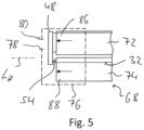
- the two main SCR catalyst units 72, 74 of the second catalyst arrangement 70 are connected to a unit generally designated 76 and shown in Fig. 5 -line is open.
- the arrangement can be such that the tubular element 54 of the second mixing section 56 penetrates the outlet housing 76 at least in some areas, so that exhaust gas flowing out of the main SCR catalyst units 72, 74 can flow around the tubular element 54 at least in some areas and in the process transfers heat to it. This can assist the evaporation of reactant in the second mixing section 56 and thus also the mixing of the reactant with the exhaust gas.
- An outlet interface 80 of the exhaust gas treatment arrangement 12 is provided on the outlet housing 76, for example, by a tubular element 78 or an opening in the outlet housing 76. With this outlet interface 80, the exhaust gas treatment arrangement 12 can be connected to a downstream, for example pipe-like system region of the exhaust system 10, so that the pollutant-reduced exhaust gas treated in the exhaust gas treatment arrangement 12 can be discharged from the exhaust gas treatment arrangement 12.
- the outlet housing 76 can be configured in multiple parts and, for example, have a detachable housing base that also provides the outlet interface 80. Alternatively or additionally, the outlet housing 76 can be configured to be opened in a lateral region in order to gain lateral access to the system regions of the exhaust gas treatment assembly 12 located inside the outlet housing 76.
- the second mixing section 56, the third deflection housing 66, the second exhaust gas treatment section 68, the outlet housing 76 and the outlet interface 80 provided thereon thus form a fifth module M5, which is detachably connected in the manner described above in the region of the inlet region 58 of the second mixing section 56 to the fourth module M4 provided essentially by the second deflection housing 48.
- each of the modules M1 to M5 can be constructed separately in order to then detachably connect the modules, which are provided with high structural strength and preferably firmly and non-detachably connected to one another in the system areas, such as deflection housings and tubular elements, in the manner described above.
- the various system regions of the exhaust gas treatment arrangement 12 which are elongated in the exhaust gas treatment arrangement longitudinal direction LA , essentially the two mixing sections 14, 56 and the two exhaust gas treatment sections 32, 68, are arranged transversely to the exhaust gas treatment arrangement longitudinal direction LA next to one another and essentially completely axially overlap one another, so that a structure is obtained in which the first deflection housing 30 and the third deflection housing 66 are positioned essentially in the same axial region or in a first axial end region 82 of the exhaust gas treatment arrangement 12 and the second deflection housing 48 is positioned substantially in a second axial end region 84 of the exhaust gas treatment arrangement 12.
- the inlet interface 18 and the outlet interface 80 are also positioned in this second axial end region 84.
- the second deflection housing 48 which essentially provides the fourth module M4, crosses the ends of the two main SCR catalyst units 72, 74, which are generally open for the outflow of exhaust gas, transversely to the exhaust gas treatment arrangement longitudinal axis L A .
- first exhaust gas treatment section 32 and the second mixing section 56 or their respective longitudinal axes defining longitudinal directions L A1 , L M2 on the one hand and longitudinal center axes of the two main SCR catalyst units 72, 74 extending substantially in the second exhaust gas treatment section longitudinal direction L A2 on the other hand are opposite one another in pairs with respect to the exhaust gas treatment arrangement longitudinal direction L A substantially defining a longitudinal center axis of the exhaust gas treatment arrangement 12, so that a line connecting the first exhaust gas treatment section longitudinal direction L A1 and the second mixing section longitudinal direction L M2 and each orthogonal to these directions and a line connecting the longitudinal center axes of the two main SCR catalyst units 72, 74 and each orthogonal to these directions intersect one another.
- one of the main SCR catalyst units 72, 74 thus follows the first exhaust gas treatment section 32
- the second mixing section 56 follows this main SCR catalyst unit of the two main SCR catalyst units 72, 74
- the other of the two main SCR catalyst units 72, 74 follows the second mixing section 56 and then the first exhaust gas treatment section 32 follows the other of the two main SCR catalyst units 72, 74.
- the detachable connection of modules M1 to M5 to one another makes it possible to carry out maintenance and repair work in a simple manner.
- the particulate filter assembly 36 which is heavily exposed to contamination, can be easily removed from the exhaust gas treatment assembly 12 by opening its detachable connections to the second module M2 on the one hand and the fourth module M4 on the other. It can be cleaned or replaced with a new or clean particulate filter assembly. Since the modules M2 and M5 containing the respective catalyst units or catalyst blocks can also be removed as such from the exhaust gas treatment assembly 12, it is also possible, if necessary, to clean the catalyst units or catalyst blocks present in these modules or to insert new modules M2, M5 into the exhaust gas treatment assembly 12.
- the second exhaust gas treatment section 68 which takes over the essential part of the nitrogen oxide reduction, comprises two main SCR catalyst units 72, 74 through which flow can occur in parallel.
Landscapes
- Engineering & Computer Science (AREA)
- Chemical & Material Sciences (AREA)
- Combustion & Propulsion (AREA)
- Mechanical Engineering (AREA)
- General Engineering & Computer Science (AREA)
- Chemical Kinetics & Catalysis (AREA)
- Health & Medical Sciences (AREA)
- Toxicology (AREA)
- Materials Engineering (AREA)
- Exhaust Gas After Treatment (AREA)
Description
- Die vorliegende Erfindung betrifft modulartig aufgebaute Abgasbehandlungsanordnungen, welche insbesondere in Abgasanlagen von in Fahrzeugen eingesetzten Brennkraftmaschinen zur Verringerung des Schadstoffausstoßes beitragen.
- Derartige beispielsweise in Zuordnung von Diesel-Brennkraftmaschinen eingesetzte Abgasbehandlungsanordnungen umfassen in Strömungsrichtung aufeinander folgend im Allgemeinen einen Diesel-Oxidationskatalysator, einen Diesel-Partikelfilter und einen SCR-Katalysator. Stromaufwärts des SCR-Katalysators ist eine Mischstrecke vorgesehen, in welcher Abgas und durch eine Reaktionsmittelabgabeanordnung, im Allgemeinen als Injektor bezeichnet, abgegebenes Reaktionsmittel, beispielsweise eine Harnstoff/Wasser-Lösung, zur nachfolgenden Durchführung einer selektiven katalytischen Reduktion im SCR-Katalysator vermischt und umgesetzt werden. Um den strenger werdenden Abgasnormen gerecht werden zu können, kann es erforderlich sein, diesen zur Abgasbehandlung vorgesehenen Systembereichen einen weiteren SCR-Katalysator vorzuschalten. In Zuordnung zu diesem weiteren SCR-Katalysator, im Allgemeinen als Vor-SCR-Katalysator bezeichnet, ist eine weitere Mischstrecke erforderlich, um stromaufwärts dieses Vor-SCR-Katalysators Abgas mit Reaktionsmittel zu vermischen und dem Vor-SCR-Katalysator zuzuführen.
- Da in Fahrzeugen, wie zum Beispiel auch Nutzkraftfahrzeugen bzw. Lastkraftfahrzeugen, der zur Aufnahme von Abgasbehandlungsanordnungen zur Verfügung stehenden Bauraum begrenzt ist und auch dadurch vorgegeben ist, wo in derartigen Fahrzeugen die stromaufwärtigen bzw. stromabwärtigen Anschlussbereiche für die Integration einer Abgasbehandlungsanordnung in eine Abgasanlage vorgesehen sind, besteht grundsätzlich die Anforderung, weitere Systembereiche enthaltende Abgasbehandlungsanordnungen auch unter Beibehalt bzw. Erreichung eines optimalen Strömungsverhaltens bei möglichst geringem Gegendruck in dem Bauraum unterzubringen, der bei bereits bestehenden bzw. konzipierten Fahrzeugen zur Verfügung steht. Dies erfordert, dass auch bei Integration weiterer Systembereiche in derartige Abgasbehandlungsanordnungen deren Außenabmessungen von den Außenabmessungen bereits bestehender Abgasbehandlungsanordnungen nicht bzw. nicht wesentlich abweichen dürfen. Gleichzeitig muss die Möglichkeit bestehen bzw. erhalten bleiben, Zugriff auf Systembereiche derartiger Abgasbehandlungsanordnungen, die im Abgasbehandlungsbetrieb degradieren und daher einer Wartung bzw. eines Austauschs bedürfen, zu haben.
- Eine modulartig aufgebaute Abgasbehandlungsanordnung gemäß dem Oberbegriff des Anspruchs 1 ist aus der
US 2022/0356832 A1 bekannt. Bei dieser modulartig aufgebauten Abgasbehandlungsanordnung sind eine Eintrittsschnittstelle, eine in Strömungsrichtung auf die Eintrittsschnittstelle folgende erste Mischstrecke, eine in Strömungsrichtung auf die erste Mischstrecke folgende erste Abgasbehandlungsstrecke, eine in Strömungsrichtung auf die erste Abgasbehandlungsstrecke folgende zweite Mischstrecke, eine in Strömungsrichtung auf die zweite Mischstrecke folgende zweite Abgasbehandlungsstrecke, ein einen Austrittsbereich der ersten Mischstrecke mit einem Eintrittsbereich der ersten Abgasbehandlungsstrecke verbindendes erstes Umlenkgehäuse, ein einen Austrittsbereich der ersten Abgasbehandlungsstrecke mit einem Eintrittsbereich der zweiten Mischstrecke verbindendes zweites Umlenkgehäuse und ein einen Austrittsbereich der zweiten Mischstrecke mit einem Eintrittsbereich der zweiten Abgasbehandlungsstrecke verbindendes drittes Umlenkgehäuse zu einem Modul der Abgasbehandlungsanordnung zusammengefasst. Im ersten Umlenkgehäuse ist eine durch ein Abschlusselement verschließbare Öffnung ausgebildet. Durch diese Öffnung hindurch kann erforderlichenfalls ein einen SCR-Katalysator und einen Dieseloxidationskatalysator der ersten Abgasbehandlungsstrecke umfassendes weiteres Modul der Abgasbehandlungsanordnung aus einem Gehäuse der ersten Abgasbehandlungsstrecke entfernt und durch ein entsprechendes einen SCR-Katalysator und einen Dieseloxidationskatalysator umfassendes Modul ersetzt werden. - Es ist die Aufgabe der vorliegenden Erfindung, eine Abgasbehandlungsanordnung, insbesondere für eine Abgasanlage einer Brennkraftmaschine in einem Fahrzeug, vorzusehen, welche bei verbessertem Abgasbehandlungsvermögen die Möglichkeit der Wartung bzw. des Austauschs von Systembereichen derselben bietet.
- Erfindungsgemäß wird diese Aufgabe gelöst durch eine modulartig aufgebaute Abgasbehandlungsanordnung, umfassend:
- eine Eintrittsschnittstelle zur Aufnahme von Abgas in der Abgasbehandlungsanordnung,
- eine erste Mischstrecke,
- eine erste Abgasbehandlungsstrecke mit einer ersten Katalysatoranordnung und einer Partikelfilteranordnung,
- eine zweite Mischstrecke,
- eine zweite Abgasbehandlungstrecke mit einer zweiten Katalysatoranordnung,
- ein einen Austrittsbereich der ersten Mischstrecke mit einem Eintrittsbereich der ersten Abgasbehandlungsstrecke verbindendes erstes Umlenkgehäuse,
- ein einen Austrittsbereich der ersten Abgasbehandlungsstrecke mit einem Eintrittsbereich der zweiten Mischstrecke verbindendes zweites Umlenkgehäuse,
- ein einen Austrittsbereich der zweiten Mischstrecke mit einem Eintrittsbereich der zweiten Abgasbehandlungsstrecke verbindendes drittes Umlenkgehäuse.
- Bei dieser Abgasbehandlungsanordnung ist erfindungsgemäß weiter vorgesehen, dass:
- ein erstes Modul die Eintrittsschnittstelle und die erste Mischstrecke umfasst,
- ein zweites Modul das erste Umlenkgehäuse und die erste Katalysatoranordnung der ersten Abgasbehandlungsstrecke umfasst, wobei das zweite Modul mit dem ersten Modul lösbar verbunden ist,
- ein drittes Modul die Partikelfilteranordnung der ersten Abgasbehandlungsstrecke umfasst, wobei das dritte Modul mit dem zweiten Modul lösbar verbunden ist,
- ein viertes Modul das zweite Umlenkgehäuse umfasst, wobei das vierte Modul mit dem dritten Modul lösbar verbunden ist,
- ein fünftes Modul die zweite Mischstrecke, das dritte Umlenkgehäuse und die zweite Abgasbehandlungsstrecke umfasst, wobei das fünfte Modul mit dem vierten Modul lösbar verbunden ist.
- Durch die Aufgliederung der Abgasbehandlungsanordnung in eine Mehrzahl von miteinander lösbar verbundenen Modulen besteht die Möglichkeit, jedes derartige Modul für sich alleine und losgelöst von anderen Modulen aufzubauen und als solches in die Abgasbehandlungsanordnung zu integrieren bzw. zur Durchführung von Wartungs- oder Erneuerungsarbeiten aus dieser zu entnehmen. Gleichzeitig unterstützt die Verwendung einer Mehrzahl von Modulen in der Abgasbehandlungsanordnung eine derartige räumliche Positionierung der einzelnen Module bzw. der Systembereiche der einzelnen Module zueinander, dass eine kompakte Bauart erhalten wird, welche es gestattet, eine insbesondere auch eine weitere Mischstrecke enthaltende Abgasbehandlungsanordnung in den bei bereits aufgebauten bzw. konzipierten Fahrzeugen zur Verfügung stehenden Bauraum zu integrieren.
- Für eine einfach zu realisierende, gleichwohl zuverlässige und gasdichte Verbindung der Module miteinander wird vorgeschlagen, dass wenigstens ein Modul von erstem Modul, zweitem Modul, drittem Modul, viertem Modul und fünftem Modul mit wenigstens einem weiteren Modul von erstem Modul, zweitem Modul, drittem Modul, viertem Modul und fünftem Modul durch eine Schraubverbindung oder/und eine Schellenverbindung lösbar verbunden ist.
- Es ist in diesem Zusammenhang darauf hinzuweisen, dass dann, wenn zwei Module im Bereich rohrartiger Elemente aneinander anschließen und miteinander lösbar zu verbinden sind, die rohrartigen Elemente mit flanschartigen Enden derselben gegebenenfalls unter Zwischenlagerung eines Dichtungselements aneinander angrenzend positioniert werden können und durch eine die flanschartigen Enden außen umgreifende Rohrschelle oder durch durch die flanschartigen Enden hindurchgeführte bzw. diese miteinander koppelnde Schraubbolzen oder dergleichen miteinander verbunden werden können. Zur lösbaren Anbindung eines rohrartigen Elements eines Moduls an ein Umlenkgehäuse eines anderen Moduls kann ein flanschartig ausgebildetes Ende des rohrartigen Elements durch dieses und eine Wand des Umlenkgehäuses durchgreifende bzw. daran vorgesehenen Schraubbolzen oder dergleichen an das Umlenkgehäuse angebunden werden. Alternativ kann zur Anbindung eines rohrartigen und mit einem flanschartigen Ende aufgebauten Elements eines Moduls an ein Umlenkgehäuse das Umlenkgehäuse einen von einer Wand desselben hervorstehenden, rohrartigen bzw. stutzenartigen Bereich mit einem flanschartigen Ende aufweisen, der dem flanschartigen Ende des rohrartig aufgebauten Elements gegebenenfalls unter Zwischenlagerung eines Dichtungselements gegenüberliegend positioniert wird und vermittels einer diese flanschartigen Enden außen umgreifenden Rohrschelle oder einer Mehrzahl von die flanschartigen Enden durchgreifenden bzw. miteinander koppelnden Schraubbolzen oder dergleichen verbunden wird.
- Zur lösbaren Verbindung des ersten Moduls mit dem zweiten Modul kann der Austrittsbereich der ersten Mischstrecke mit einem Eintrittsbereich des ersten Umlenkgehäuses lösbar verbunden sein.
- Das zweite Modul kann mit dem dritten Modul in einfacher Weise dadurch lösbar gekoppelt sein, dass ein Austrittsbereich der ersten Katalysatoranordnung mit einem Eintrittsbereich der Partikelfilteranordnung lösbar verbunden ist.
- Das dritte Modul kann an das vierte Modul dadurch lösbar angebunden sein, dass ein Austrittsbereich der Partikelfilteranordnung mit einem Eintrittsbereich des zweiten Umlenkgehäuses lösbar verbunden ist.
- Zur lösbaren Verbindung des vierten Moduls mit dem fünften Modul wird vorgeschlagen, dass ein Austrittsbereich des zweiten Umlenkgehäuses mit dem Eintrittsbereich der zweiten Mischstrecke lösbar verbunden ist.
- Zur effizienten Minderung des Stickoxidanteils in dem von einer Brennkraftmaschine, insbesondere einer Diesel-Brennkraftmaschine, ausgestoßenen Abgas wird vorgeschlagen, dass die erste Katalysatoranordnung eine Vor-SCR-Katalysatoreinheit umfasst, und dass das erste Modul eine erste Reaktionsmittelschnittstelle zur Aufnahme einer ersten Reaktionsmittelabgabeanordnung aufweist.
- Beispielsweise kann die erste Reaktionsmittelschnittstelle im Bereich des Eintrittsbereichs der ersten Mischstrecke vorgesehen sein.
- Die erste Katalysatoranordnung kann ferner eine Oxidationskatalysatoreinheit umfassen.
- Um den Stickoxidanteil in dem von einer Brennkraftmaschine ausgestoßenen Abgas so weit als möglich zu senken, kann die zweite Katalysatoranordnung wenigstens eine Haupt-SCR-Katalysatoreinheit umfassen, und das vierte Modul kann eine zweite Reaktionsmittelschnittstelle zur Aufnahme einer zweiten Reaktionsmittelabgabeanordnung aufweisen.
- Um die Kapazität der zweiten Katalysatoranordnung zur Minderung des Stickoxidanteils möglichst groß zu gestalten, kann diese zwei zueinander parallel geschaltete Haupt-SCR-Katalysatoreinheiten umfassen.
- Zum Erreichen einer kompakten Ausgestaltung wird vorgeschlagen, dass in Umfangsrichtung um eine Längsmittenachse der Abgasbehandlungsanordnung eine der Haupt-SCR-Katalysatoreinheiten auf die erste Abgasbehandlungsstrecke folgt, die zweite Mischstrecke auf die eine Haupt-SCR-Katalysatoreinheit der beiden Haupt-SCR-Katalysatoreinheiten folgt, die andere Haupt-SCR-Katalysatoreinheit der beiden Haupt-SCR-Katalysatoreinheiten auf die zweite Mischstrecke folgt und die erste Abgasbehandlungsstrecke auf die andere Haupt-SCR-Katalysatoreinheit der beiden Haupt-SCR-Katalysatoreinheiten folgt.
- Eine kompakte Bauart der erfindungsgemäßen Abgasbehandlungsanordnung kann weiter dadurch unterstützt werden, dass die erste Mischstrecke in Richtung einer zu einer Abgasbehandlungsanordnung-Längsachse im Wesentlichen parallelen ersten Mischstrecken-Längsachse langgestreckt ist, dass die zweite Mischstrecke in Richtung einer zu der Abgasbehandlungsanordnung-Längsachse im Wesentlichen parallelen zweiten Mischstrecken-Längsachse langgestreckt ist, dass die erste Abgasbehandlungsstrecke in Richtung einer zu der Abgasbehandlungsanordnung-Längsachse im Wesentlichen parallelen ersten Abgasbehandlungsstrecken-Längsachse langgestreckt ist, dass die zweite Abgasbehandlungsstrecke in Richtung einer zu der Abgasbehandlungsanordnung-Längsachse im Wesentlichen parallelen zweiten Abgasbehandlungsstrecke-Längsachse langgestreckt ist, und dass die erste Mischstrecke, die zweite Mischstrecke, die erste Abgasbehandlungsstrecke und die zweite Abgasbehandlungsstrecke einander in Richtung der Abgasbehandlungsanordnung-Längsachse überlappend angeordnet sind.
- Wenn dabei das erste Umlenkgehäuse und das dritte Umlenkgehäuse in einem ersten axialen Endbereich der Abgasbehandlungsanordnung bezüglich einer Abgasbehandlungsanordnung-Längsachse angeordnet sind und das zweite Umlenkgehäuse in einem zweiten axialen Endbereich bezüglich der Abgasbehandlungsanordnung-Längsachse angeordnet ist, liegen im Wesentlichen alle in Richtung der Abgasbehandlungsanordnung-Längsachse sich erstreckenden Systembereiche im gleichen axialen Bereich bzw. einander im Wesentlichen vollständig überlappend, so dass eine in Richtung der Abgasbehandlungsanordnung-Längsachse kompakte Bauart erreicht wird.
- Zur Abgabe von behandeltem Abgas aus der Abgasbehandlungsanordnung kann ein Austrittsgehäuse vorgesehen sein, wobei ein Austrittsbereich der zweiten Abgasbehandlungsstrecke zu dem Austrittsgehäuse offen ist, und an dem Austrittsgehäuse kann eine Austrittsschnittstelle zur Abgabe von Abgas aus der Abgasbehandlungsanordnung vorgesehen sein. Beispielsweise kann das Austrittsgehäuse einen Bestandteil des fünften Moduls bilden.
- Zur Unterstützung der Durchmischung von Abgas und Reaktionsmittel in der zweiten Mischstrecke kann wenigstens ein Teil der zweiten Mischstrecke sich im Inneren des Austrittsgehäuses erstrecken.
- Die Erfindung betrifft ferner eine Abgasanlage für eine Brennkraftmaschine, umfassend eine erfindungsgemäß aufgebaute Abgasbehandlungsanordnung.
- Die vorliegende Erfindung wird nachfolgend mit Bezug auf die beiliegenden Figuren detailliert beschrieben. Es zeigt:
- Fig. 1
- eine prinzipartige Draufsicht auf eine Abgasbehandlungsanordnung in Blickrichtung I in
Fig. 2 ; - Fig. 2
- die Abgasbehandlungsanordnung der
Fig. 1 in Blickrichtung II inFig. 1 ; - Fig. 3
- die Abgasbehandlungsanordnung der
Fig. 1 in Blickrichtung III inFig1 ; - Fig. 4
- in prinzipartiger Darstellung die lösbare Verbindung zweier Module der Abgasbehandlungsanordnung der
Fig. 1 ; - Fig. 5
- in prinzipartiger Darstellung den Bereich der Abgasbehandlungsanordnung der
Fig. 1 , in welchem das in der Abgasbehandlungsanordnung behandelte Abgas an einer Austrittsschnittstelle die Abgasbehandlungsanordnung verlässt. - In den Figuren ist eine prinzipartig dargestellte Abgasbehandlungsanordnung für eine Abgasanlage 10 einer Brennkraftmaschine allgemein mit 12 bezeichnet. Die Abgasanlage 12 ist grundsätzlich modulartig aufgebaut und umfasst fünf nachfolgend im Einzelnen beschriebene Module M1 bis M5, die miteinander lösbar verbunden sind.
- Ein erstes Modul M1 umfasst eine beispielsweise mit einem rohrartigen Element 26 aufgebaute erste Mischstrecke 14. An einem Eintrittsbereich 16 der ersten Mischstrecke 14 ist eine beispielsweise mit einem Rohrabschnitt oder einem Rohrstutzen aufgebaute Eintrittsschnittstelle 18 der Abgasbehandlungsanordnung 12 vorgesehen, mit welcher diese an einen stromaufwärtigen Bereich der Abgasanlage 10 angebunden werden kann. Von einer Brennkraftmaschine ausgestoßenes Abgas A tritt im Bereich der Eintrittsschnittstelle 18 in die Abgasanlage 12 ein.
- Im Bereich des Eintrittsbereichs 16 der ersten Mischstrecke 14 bzw. an dem auch die Eintrittsschnittstelle 18 bereitstellenden rohrartigen Element 20 ist eine erste Reaktionsmittelschnittstelle 22 vorgesehen. Im Bereich der ersten Reaktionsmittelschnittstelle 22 kann eine allgemein auch als Injektor bezeichnete erste Reaktionsmittelabgabeanordnung 24 an das Modul M1 in einem stromaufwärtigen Bereich der ersten Mischstrecke 14 angebunden werden. Durch die erste Reaktionsmittelabgabeanordnung 24 kann ein Reaktionsmittel, beispielsweise eine Harnstoff/Wasser-Lösung, in das im Bereich der Eintrittsschnittstelle 18 in die Abgasanlage 12 einströmende Abgas A eingeleitet werden. Zur effizienten Durchmischung von im Allgemeinen als Sprühnebel abgegebenem Reaktionsmittel mit dem Abgas A kann in der ersten Mischstrecke 14 beispielsweise ein mit einer Vielzahl von schaufelartigen Ablenkelementen oder dergleichen aufgebauter Mischer angeordnet sein. Beim Strömen entlang des im Wesentlichen in einer ersten Mischstrecken-Längsrichtung LM1 langgestreckten rohrartigen Elements 26 der ersten Mischstrecke 14 durchmischt sich das Abgas A mit dem Reaktionsmittel.
- Ein stromabwärtiger Austrittsbereich 28 der ersten Mischstrecke 14 ist, wie durch einen in Strichlinie angedeuteten Bereich veranschaulicht, mit einem ersten Umlenkgehäuse 30 lösbar verbunden. Dazu kann ein im unteren Teil der in
Fig.4 erkennbares flanschartiges Ende 100 des rohrartigen Elements 26 der ersten Mischstrecke 14 durch eine Mehrzahl von Schraubbolzen 102 oder dergleichen an eine Wand 104 des ersten Umlenkgehäuses 30 lösbar angebunden sein. Alternativ kann, wie im oberen Teil derFig. 4 veranschaulicht, an der Wand 100 des ersten Umlenkgehäuses 30 ein mit einem flanschartigen Ende 106 ausgebildeter Rohrstutzen 108 vorgesehen sein, wobei die dann aneinander anliegenden flanschartigen Enden 100, 106 am rohrartigen Element 26 einerseits und am ersten Umlenkgehäuse 30 andererseits durch eine Mehrzahl von Schraubbolzen oder durch eine diese umgebende Rohrschelle 110 miteinander fest und gasdicht verbunden werden können. - Das im Austrittsbereich 28 der ersten Mischstrecke 14 in das erste Umlenkgehäuse 30 in einem Eintrittsbereich 31 desselben eingeleitete Abgas bzw. Gemisch aus Abgas und Reaktionsmittel wird im ersten Umlenkgehäuse 30 bezüglich einer Abgasbehandlungsanordnung-Längsrichtung LA um etwa 180° umgelenkt und verlässt das erste Umlenkgehäuse 30 in Richtung zu einer ersten Abgasbehandlungsstrecke 32. Die erste Abgasbehandlungsstrecke 32 umfasst in Strömungsrichtung aufeinander folgend eine erste Katalysatoranordnung 34 und eine Partikelfilteranordnung 36. Die erste Katalysatoranordnung 34 umfasst eine Vor-SCR-Katalysatoreinheit 38 und beispielsweise stromabwärts derselben eine Oxidationskatalysatoreinheit 40.
- Das erste Umlenkgehäuse 30 bildet mit der ersten Katalysatoranordnung 34 der grundsätzlich in einer ersten Abgasbehandlungsanordnung-Längsrichtung LA1 langgestreckten und in diese Richtung auch durchströmbaren ersten Abgasbehandlungsstrecke 32 ein zweites Modul M2. Hierzu kann beispielsweise ein die Vor-SCR-Katalysatoreinheit 38 und die Oxidationskatalysatoreinheit 40 unter Zwischenlagerung von beispielsweise faserartigem bzw. mattenartigem Lagermaterial aufnehmender rohrartiger Mantel der ersten Katalysatoranordnung 34 an eine Wand des ersten Umlenkgehäuses 30 fest, beispielsweise durch Materialschluss angebunden sein. Alternativ kann ein rohrartiges Gehäuse der ersten Katalysatoranordnung 34 an das erste Umlenkgehäuse 30 fest angebunden sein. In diesem rohrartigen Gehäuse können dann die Vor-Katalysatoreinheit 38 bzw. die Oxidationskatalysatoreinheit 40 aufgenommen sein. Jede dieser Einheiten kann dann wiederum mit einem Mantel und dem darin beispielsweise unter Zwischenlagerung von faserartigem bzw. mattenartigem Material aufgenommenen Katalysatorblock aufgebaut sein.
- Die Partikelfilteranordnung 36 bildet ein drittes Modul M3 der Abgasbehandlungsanordnung 10. Ein Eintrittsbereich 42 der Partikelfilteranordnung 36 ist mit einem Austrittsbereich 44 der ersten Katalysatoranordnung 34, wie durch eine Strichlinie angedeutet, lösbar verbunden. Hierzu können die erster Katalysatoranordnung 34 und die Partikelfilteranordnung 36, welche grundsätzlich mit rohrartigen Gehäuseelementen bzw. Mänteln aufgebaut sind, in ihren aneinander anschließenden Enden, also im Eintrittsbereich 42 und im Austrittsbereich 44, flanschartig ausgebildet sein und durch eine diese umgreifende Rohrschelle oder durch eine Mehrzahl von Schraubbolzen lösbar und gasdicht miteinander verbunden sein.
- Ein Austrittsbereich 46 der Partikelfilteranordnung 36 schließt lösbar an ein zweites Umlenkgehäuse 48 an. Das zweite Umlenkgehäuse 48 bildet in der Abgasbehandlungsanordnung 12 ein viertes Modul M4. Ein Eintrittsbereich 50 des zweiten Umlenkgehäuses 48 ist mit dem Austrittsbereich 46 der Partikelfilteranordnung beispielsweise in einer Art und Weise, wie dies vorangehend mit Bezug auf die Verbindung des ersten Umlenkgehäuses 30 mit der ersten Mischstrecke 14 beschrieben wurde, durch eine Rohrschelle oder durch eine Mehrzahl von Schraubbolzen oder dergleichen lösbar und gasdicht verbunden.
- Im zweiten Umlenkgehäuse 48 wird das aus der ersten Abgasbehandlungsstrecke 32 in Richtung der ersten Abgasbehandlungsstrecken-Längsachse LA1 bzw. in Richtung der Abgasbehandlungsanordnung-Längsachse LA strömende Abgas bzw. Gemisch aus Abgas und Reaktionsmittel umgelenkt, und im Bereich eines Austrittsbereichs 52 des zweiten Umlenkgehäuses 48 verlässt das Abgas das im Wesentlichen durch das zweite Umlenkgehäuse 48 bereitgestellte vierte Modul M4 in Richtung zu einer im Wesentlichen ein rohrartiges Element 54 umfassenden zweiten Mischstrecke 56. Ein Eintrittsbereich 58 der zweiten Mischstrecke 56 ist lösbar mit dem Austrittsbereich 52 des zweiten Umlenkgehäuses 48 verbunden. Auch hier kann die lösbare Verbindung in der vorangehend mit Bezug auf die lösbare Verbindung zwischen dem Austrittsbereich 28 der ersten Mischstrecke 14 und dem Eintrittsbereich 31 des ersten Umlenkgehäuses 30 beschriebenen Art und Weise verbunden sein.
- In Zuordnung zu der zweiten Mischstrecke 56 ist am vierten Modul M4 bzw. am zweiten Umlenkgehäuse 48 eine zweite Reaktionsmittelschnittstelle 60 vorgesehen. Im Bereich der im Wesentlichen dem Eintrittsbereich 58 der zweiten Mischstrecke 56 gegenüberliegenden zweiten Reaktionsmittelschnittstelle 60 ist eine zweite Reaktionsmittelabgabeanordnung 62 am zweiten Umlenkgehäuse 48 festgelegt, so dass von der zweiten Reaktionsmittelabgabeanordnung 62 abgegebenes Reaktionsmittel, beispielsweise eine Harnstoff/Wasser-Lösung, zusammen mit dem das zweite Umlenkgehäuse 48 durchströmenden Abgas in den Eintrittsbereich 58 der zweiten Mischstrecke 56 eingeleitet wird. In dem in einer zweiten Mischstrecken-Längsrichtung LM2 langgestreckten, rohrartigen Element 54 der zweiten Mischstrecke 56 strömt das Gemisch aus Abgas und Reaktionsmittel, wobei zum Unterstützen der Durchmischung in dem rohrartigen Element 54 ein eine Mehrzahl von Ablenkschaufeln oder dergleichen umfassender Mischer angeordnet sein kann.
- An einem Austrittsbereich 64 der zweiten Mischstrecke 56 schließt diese an ein drittes Umlenkgehäuse 66 an. Dabei kann das rohrartige Element 54 der zweiten Mischstrecke 56 mit einer Wand des dritten Umlenkgehäuses 66 beispielsweise durch Verschweißen oder dergleichen fest verbunden sein.
- Es ist darauf hinzuweisen, dass die in der Abgasbehandlungsanordnung 12 vorgesehenen Umlenkgehäuse 30, 48, 66 dort, wo an jeweilige Eintrittsbereiche bzw. Austrittsbereiche derselben die Mischstrecken 14, 56 bzw. die Abgasbehandlungsstrecken 32, 68 anschließen, Öffnungen aufweisen, um den Eintritt bzw. den Austritt von Abgas und gegebenenfalls Reaktionsmittel in bzw. aus in den Umlenkgehäusen 30, 48, 66 gebildeten Umlenkkammern zu ermöglichen.
- In dem dritten Umlenkgehäuse 66 wird das die zweite Mischstrecke 56 verlassende Gemisch aus Abgas und Reaktionsmittel um etwa 180° in Richtung zu einer allgemein mit 68 bezeichneten zweiten Abgasbehandlungsstrecke umgelenkt. Die zweite Abgasbehandlungsstrecke 68 umfasst eine zweite Katalysatoranordnung 70 mit zwei quer zur Abgasbehandlungs-Längsrichtung LA nebeneinander angeordneten und in einer zweiten Abgasbehandlungsstrecken-Längsrichtung LA2 langgestreckten Haupt-SCR-Katalysatoreinheiten 72, 74. Jede der Haupt-SCR-Katalysatoreinheiten 72, 74 kann einen rohrartigen Mantel aufweisen, welcher an eine Wand des dritten Umlenkgehäuses 66 durch Verschweißen oder dergleichen fest und gasdicht angebunden sein kann und in welchem jeweils zumindest ein Katalysatorblock unter Zwischenlagerung von faserartigem bzw. mattenartigem Material gehalten sein kann. Alternativ kann jede der Haupt-SCR-Katalysatoreinheiten 72, 74 ein an das dritte Umlenkgehäuse 66 beispielsweise durch Verschweißen oder dergleichen fest angebundenes rohrartiges Gehäuse aufweisen, in welches dann jeweils zumindest eine Katalysatoreinheit jeweils mit einem rohrartigen Mantel und einem darin beispielsweise durch faserartiges Material oder Mattenmaterial gehaltenem Katalysatorblock aufgenommen sein kann.
- An ihren stromabwärtigen Enden 86, 88 sind die beiden Haupt-SCR-Katalysatoreinheiten 72, 74 der zweiten Katalysatoranordnung 70 zu einem allgemein mit 76 bezeichneten und in
Fig. 5 -Linie angedeuteten Austrittsgehäuse offen. Die Anordnung kann derart sein, dass das rohrartige Element 54 der zweiten Mischstrecke 56 das Austrittsgehäuse 76 wenigstens bereichsweise durchsetzt, so dass aus den Haupt-SCR-Katalysatoreinheiten 72, 74 ausströmendes Abgas das rohrartige Element 54 zumindest bereichsweise umströmen kann und dabei Wärme auf dieses überträgt. Dadurch kann die Verdampfung von Reaktionsmittel in der zweiten Mischstrecke 56 und damit auch die Durchmischung des Reaktionsmittels mit dem Abgas unterstützt werden. An dem Austrittsgehäuse 76 ist eine beispielsweise durch ein rohrartiges Element 78 oder eine Öffnung in dem Austrittsgehäuse 76 bereitgestellte Austrittsschnittstelle 80 der Abgasbehandlungsanordnung 12 vorgesehen. Mit dieser Austrittsschnittstelle 80 kann die Abgasbehandlungsanordnung 12 an einen stromabwärts folgenden, beispielsweise rohrartigen Systembereich der Abgasanlage 10 angeschlossen werden, so dass das in der Abgasbehandlungsanordnung 12 behandelte, schadstoffreduzierte Abgas aus der Abgasbehandlungsanordnung 12 abgeleitet werden kann. - Um Zugriff auf das im Wesentlichen durch das zweite Umlenkgehäuse 48 bereitgestellte vierte Modul M4 sowie auch die im Wesentlichen das zweite dritte Modul M3 bereitstellende Partikelfilteranordnung 36 zu erhalten, kann das Austrittsgehäuse 76 mehrteilig ausgebildet sein und beispielsweise einen auch die Austrittschnittstelle 80 bereitstellenden, lösbaren Gehäuseboden aufweisen. Alternativ oder zusätzlich kann das Austrittsgehäuse 76 in einem seitlichen Bereich zum Öffnen ausgebildet sein, um seitlich Zugriff auf die im Inneren des Austrittsgehäuses 76 liegenden Systembereichen der Abgasbehandlungsanordnung 12 zu erhalten.
- Bei der in den
Fig. 1 bis 3 dargestellten Abgasbehandlungsanordnung 12 bilden somit die zweite Mischstrecke 56, das dritte Umlenkgehäuse 66, die zweite Abgasbehandlungsstrecke 68, das Austrittsgehäuse 76 und die daran vorgesehene Austrittsschnittstelle 80 ein fünftes Modul M5, welches in der vorangehend beschriebenen Art und Weise im Bereich des Eintrittsbereichs 58 der zweiten Mischstrecke 56 lösbar an das im Wesentlichen durch das zweite Umlenkgehäuse 48 bereitgestellte vierte Modul M4 angebunden ist. - Durch den modulartigen Aufbau der Abgasbehandlungsanordnung 12 wird eine kompakte Struktur erreicht, bei welcher jedes der Module M1 bis M5 für sich separat aufgebaut werden kann, um die in sich mit hoher struktureller Festigkeit und vorzugsweise fest und unlösbar miteinander verbundenen Systembereichen, wie zum Beispiel Umlenkgehäusen und rohrartigen Elementen, bereitgestellten Module dann in der vorangehend beschriebenen Art und Weise miteinander lösbar zu verbinden. Dabei liegen die verschiedenen in der Abgasbehandlungsanordnung-Längsrichtung LA langgestreckten Systembereiche der Abgasbehandlungsanordnung 12, im Wesentlichen also die beiden Mischstrecken 14, 56 und die beiden Abgasbehandlungsstrecken 32, 68, quer zur Abgasbehandlungsanordnung-Längsrichtung LA nebeneinander und einander im Wesentlichen vollständig axial überlappend, so dass sich eine Struktur ergibt, bei welcher das erste Umlenkgehäuse 30 und das dritte Umlenkgehäuse 66 im Wesentlichen im gleichen axialen Bereich bzw. in einem ersten axialen Endbereich 82 der Abgasbehandlungsanordnung 12 positioniert sind und das zweite Umlenkgehäuse 48 im Wesentlichen in einem zweiten axialen Endbereich 84 der Abgasbehandlungsanordnung 12 positioniert ist. In diesem zweiten axialen Endbereich 84 sind auch die Eintrittsschnittstelle 18 und die Austrittsschnittstelle 80 positioniert. Somit ergibt sich eine in den
Fig. 1 bis 3 durch Strichlinie angedeutete, grundsätzlich quaderartige Außenumfangskontur der gesamten Abgasbehandlungsanordnung 12, welche in den dafür in Fahrzeugen, insbesondere in Nutzkraftfahrzeugen bzw. Lastkraftfahrzeugen, vorgesehenen Bauraum integriert werden kann. - Aufgrund der vorangehend beschriebenen Anordnung der verschiedenen Systembereiche der Abgasbehandlungsanordnung 12 in verschiedenen definiert zueinander positionierten Modulen wird es dabei auch möglich, die erste Mischstrecke 14 und die Vor-SCR-Katalysatoreinheit 38 in den für eine derartige Abgasbehandlungsanordnung 12 bereitgestellten Bauraum zu integrieren. Bei dieser kompakten Positionierung der verschiedenen Module zueinander überkreuzt das im Wesentlichen das vierte Modul M4 bereitstellende zweite Umlenkgehäuse 48 die zum Ausströmen von Abgas grundsätzlich offenen Enden der beiden Haupt-SCR-Katalysatoreinheiten 72, 74 quer zur Abgasbehandlungsanordnung-Längsachse LA. Dies führt zu einer Struktur, bei welcher die erste Abgasbehandlungsstrecke 32 und die zweite Mischstrecke 56 bzw. deren jeweilige Längsachsen definierende Längsrichtungen LA1, LM2 einerseits und im Wesentlichen in der zweiten Abgasbehandlungsstrecken-Längsrichtung LA2 sich erstreckende Längsmittenachsen der beiden Haupt-SCR-Katalysatoreinheiten 72, 74 andererseits bezüglich der im Wesentlichen eine Längsmittenachse der Abgasbehandlungsanordnung 12 definierenden Abgasbehandlungsanordnung-Längsrichtung LA einander paarweise gegenüberliegen, so dass eine die erste Abgasbehandlungsstrecken-Längsrichtung LA1 und die zweite Mischstrecken-Längsrichtung LM2 verbindende und zu diesen Richtungen jeweils orthogonal stehende Linie und eine die Längsmittenachsen der beiden Haupt-SCR-Katalysatoreinheiten 72, 74 verbindende und zu diesen jeweils orthogonal stehende Linie einander kreuzen. In Umfangsrichtung um die im Wesentlichen eine Längsmittenachse der Abgasbehandlungsanordnung 12 definierende Abgasbehandlungsanordnung-Längsrichtung LA folgt somit eine der Haupt-SCR-Katalysatoreinheiten 72, 74 auf die erste Abgasbehandlungsstrecke 32, folgt die zweite Mischstrecke 56 auf diese Haupt-SCR-Katalysatoreinheit der beiden Haupt-SCR-Katalysatoreinheiten 72, 74, folgt die andere der beiden Haupt-SCR-Katalysatoreinheiten 72, 74 auf die zweite Mischstrecke 56 und folgt dann die erste Abgasbehandlungsstrecke 32 auf die andere der beiden Haupt-SCR-Katalysatoreinheiten 72, 74.
- Durch die lösbare Verbindung der Module M1 bis M5 miteinander, wird es möglich, in einfacher Art und Weise Wartungsarbeiten bzw. Reparaturarbeiten vorzunehmen. Beispielsweise kann die einer Verunreinigung stark ausgesetzte Partikelfilteranordnung 36 leicht durch Öffnen der lösbaren Verbindungen derselben mit dem zweiten Modul M2 einerseits und dem vierten Modul M4 andererseits aus der Abgasbehandlungsanordnung 12 herausgenommen werden und gereinigt bzw. durch eine neue oder saubere Partikelfilteranordnung ersetzt werden. Da auch die jeweilige Katalysatoreinheiten bzw. Katalysatorblöcke enthaltenden Module M2 und M5 als solche aus der Abgasbehandlungsanordnung 12 herausgelöst werden können, besteht auch die Möglichkeit, erforderlichenfalls die in diesen Modulen vorhandenen Katalysatoreinheiten bzw. Katalysatorblöcke zu reinigen bzw. neue Module M2, M5 in die Abgasbehandlungsanordnung 12 einzusetzen.
- Trotz der kompakten Bauweise wird bei der Abgasbehandlungsanordnung 12 beim Durchströmen von Abgas nur ein vergleichsweise geringer Gegendruck erzeugt, wozu insbesondere auch beiträgt, dass die den wesentlichen Anteil der Stickoxidreduktion übernehmende zweite Abgasbehandlungsstrecke 68 zwei zueinander parallel durchströmbare Haupt-SCR-Katalysatoreinheiten 72, 74 umfasst.
- Da die Bereiche, in welchen die verschiedenen Module M1 bis M5 aneinander anschließen und in der vorangehend beschriebenen Art und Weise miteinander lösbar verbunden sind, grundsätzlich von außen frei zugänglich sind, besteht in einfacher Weise die Möglichkeit, diese Bereiche der lösbaren Verbindung der verschiedenen Module miteinander visuell zu inspizieren und auf Dichtigkeit zu überprüfen. Ferner ermöglicht diese freie Zugänglichkeit auch den Einsatz herkömmlicher Werkzeuge zum Öffnen bzw. Herstellen der lösbaren Verbindung der verschiedenen Module miteinander.
Claims (17)
- Modulartig aufgebaute Abgasbehandlungsanordnung, umfassend:- eine Eintrittsschnittstelle (18) zur Aufnahme von Abgas (A) in der Abgasbehandlungsanordnung (12),- eine erste Mischstrecke (14),- eine erste Abgasbehandlungsstrecke (32) mit einer ersten Katalysatoranordnung (34) und einer Partikelfilteranordnung (36),- eine zweite Mischstrecke (56),- eine zweite Abgasbehandlungstrecke (68) mit einer zweiten Katalysatoranordnung (70),- ein einen Austrittsbereich (28) der ersten Mischstrecke (14) mit einem Eintrittsbereich der ersten Abgasbehandlungsstrecke (32) verbindendes erstes Umlenkgehäuse (30),- ein einen Austrittsbereich (46) der ersten Abgasbehandlungsstrecke (32) mit einem Eintrittsbereich (58) der zweiten Mischstrecke (56) verbindendes zweites Umlenkgehäuse (48),- ein einen Austrittsbereich (64) der zweiten Mischstrecke (56) mit einem Eintrittsbereich der zweiten Abgasbehandlungsstrecke (68) verbindendes drittes Umlenkgehäuse (66),dadurch gekennzeichnet, dass:- ein erstes Modul (M1) die Eintrittsschnittstelle (18) und die erste Mischstrecke (14) umfasst,- ein zweites Modul (M2) das erste Umlenkgehäuse (30) und die erste Katalysatoranordnung (34) der ersten Abgasbehandlungsstrecke (32) umfasst, wobei das zweite Modul (M2) mit dem ersten Modul (M1) lösbar verbunden ist,- ein drittes Modul (M3) die Partikelfilteranordnung (36) der ersten Abgasbehandlungsstrecke (32) umfasst, wobei das dritte Modul (M3) mit dem zweiten Modul (M2) lösbar verbunden ist,- ein viertes Modul (M4) das zweite Umlenkgehäuse (48) umfasst, wobei das vierte Modul (M4) mit dem dritten Modul (M3) lösbar verbunden ist,- ein fünftes Modul (M5) die zweite Mischstrecke (56), das dritte Umlenkgehäuse (66) und die zweite Abgasbehandlungsstrecke (68) umfasst, wobei das fünfte Modul (M5) mit dem vierten Modul (M4) lösbar verbunden ist.
- Abgasbehandlungsanordnung nach Anspruch 1, dadurch gekennzeichnet, dass wenigstens ein Modul von erstem Modul (M1), zweitem Modul (M2), drittem Modul (M3), viertem Modul (M4) und fünftem Modul (M5) mit wenigstens einem weiteren Modul von erstem Modul (M1), zweitem Modul (M2), drittem Modul (M3), viertem Modul (M4) und fünftem Modul (M5) durch eine Schraubverbindung oder/und eine Schellenverbindung lösbar verbunden ist.
- Abgasbehandlungsanordnung nach Anspruch 1 oder 2, dadurch gekennzeichnet, dass der Austrittsbereich (28) der ersten Mischstrecke (14) mit einem Eintrittsbereich (31) des ersten Umlenkgehäuses (30) lösbar verbunden ist.
- Abgasbehandlungsanordnung nach einem der Ansprüche 1-3, dadurch gekennzeichnet, dass ein Austrittsbereich (44) der ersten Katalysatoranordnung (34) mit einem Eintrittsbereich (42) der Partikelfilteranordnung (36) lösbar verbunden ist.
- Abgasbehandlungsanordnung nach einem der Ansprüche 1-4, dadurch gekennzeichnet, dass ein Austrittsbereich (46) der Partikelfilteranordnung (36) mit einem Eintrittsbereich (50) des zweiten Umlenkgehäuses (48) lösbar verbunden ist.
- Abgasbehandlungsanordnung nach einem der Ansprüche 1-5, dadurch gekennzeichnet, dass ein Austrittsbereich (52) des zweiten Umlenkgehäuses (48) mit dem Eintrittsbereich (58) der zweiten Mischstrecke (56) lösbar verbunden ist.
- Abgasbehandlungsanordnung nach einem der Ansprüche 1-6, dadurch gekennzeichnet, dass die erste Katalysatoranordnung (34) eine Vor-SCR-Katalysatoreinheit (38) umfasst, und dass das erste Modul (M1) eine erste Reaktionsmittelschnittstelle (22) zur Aufnahme einer ersten Reaktionsmittelabgabeanordnung (24) aufweist.
- Abgasbehandlungsanordnung nach Anspruch 7, dadurch gekennzeichnet, dass die erste Reaktionsmittelschnittstelle (22) im Bereich des Eintrittsbereichs (16) der ersten Mischstrecke (14) vorgesehen ist.
- Abgasbehandlungsanordnung nach einem der Ansprüche 1-8, dadurch gekennzeichnet, dass die erste Katalysatoranordnung (34) eine Oxidationskatalysatoreinheit (40) umfasst.
- Abgasbehandlungsanordnung nach einem der Ansprüche 1-9, dadurch gekennzeichnet, dass die zweite Katalysatoranordnung (70) wenigstens eine Haupt-SCR-Katalysatoreinheit (72, 74) umfasst, und dass das vierte Modul (M4) eine zweite Reaktionsmittelschnittstelle (60) zur Aufnahme einer zweiten Reaktionsmittelabgabeanordnung (62) aufweist.
- Abgasbehandlungsanordnung nach Anspruch 10, dadurch gekennzeichnet, dass die zweite Katalysatoranordnung (70) zwei zueinander parallel geschaltete Haupt-SCR-Katalysatoreinheiten (72, 74) umfasst.
- Abgasbehandlungsanordnung nach Anspruch 11, dadurch gekennzeichnet, dass in Umfangsrichtung um eine Längsmittenachse der Abgasbehandlungsanordnung (12) eine der Haupt-SCR-Katalysatoreinheiten (72, 74) auf die erste Abgasbehandlungsstrecke (32) folgt, die zweite Mischstrecke (56) auf die eine Haupt-SCR-Katalysatoreinheit der beiden Haupt-SCR-Katalysatoreinheiten (72, 74) folgt, die andere Haupt-SCR-Katalysatoreinheit der beiden Haupt-SCR-Katalysatoreinheiten (72, 74) auf die zweite Mischstrecke (56) folgt und die erste Abgasbehandlungsstrecke (32) auf die andere Haupt-SCR-Katalysatoreinheit der beiden Haupt-SCR-Katalysatoreinheiten (72, 74) folgt.
- Abgasbehandlungsanordnung nach einem der Ansprüche 1-12, dadurch gekennzeichnet, dass die erste Mischstrecke (14) in Richtung einer zu einer Abgasbehandlungsanordnung-Längsachse (LA) im Wesentlichen parallelen ersten Mischstrecken-Längsachse (LM1) langgestreckt ist, dass die zweite Mischstrecke (56) in Richtung einer zu der Abgasbehandlungsanordnung-Längsachse (LA) im Wesentlichen parallelen zweiten Mischstrecken-Längsachse (LM2) langgestreckt ist, dass die erste Abgasbehandlungsstrecke (32) in Richtung einer zu der Abgasbehandlungsanordnung-Längsachse (LA) im Wesentlichen parallelen ersten Abgasbehandlungsstrecken-Längsachse (LA1) langgestreckt ist, dass die zweite Abgasbehandlungsstrecke (68) in Richtung einer zu der Abgasbehandlungsanordnung-Längsachse (LA) im Wesentlichen parallelen zweiten Abgasbehandlungsstrecke-Längsachse (LA2) langgestreckt ist, und dass die erste Mischstrecke (14), die zweite Mischstrecke (56), die erste Abgasbehandlungsstrecke (32) und die zweite Abgasbehandlungsstrecke (68) einander in Richtung der Abgasbehandlungsanordnung-Längsachse (LA) überlappend angeordnet sind.
- Abgasbehandlungsanordnung nach einem der Ansprüche 1-13, dadurch gekennzeichnet, dass das erste Umlenkgehäuse (30) und das dritte Umlenkgehäuse (66) in einem ersten axialen Endbereich (82) der Abgasbehandlungsanordnung (12) bezüglich einer Abgasbehandlungsanordnung-Längsachse (LA) angeordnet sind, und dass das zweite Umlenkgehäuse (48) in einem zweiten axialen Endbereich (84) bezüglich der Abgasbehandlungsanordnung-Längsachse (LA) angeordnet ist.
- Abgasbehandlungsanordnung nach einem der Ansprüche 1-14, dadurch gekennzeichnet, dass ein Austrittsgehäuse (76) vorgesehen ist, wobei ein Austrittsbereich der zweiten Abgasbehandlungsstrecke (68) zu dem Austrittsgehäuse (76) offen ist, und dass an dem Austrittsgehäuse (76) eine Austrittsschnittstelle (80) zur Abgabe von Abgas (A) aus der Abgasbehandlungsanordnung (12) vorgesehen ist.
- Abgasbehandlungsanordnung nach Anspruch 15, dadurch gekennzeichnet, dass wenigstens ein Teil der zweiten Mischstrecke (56) sich im Inneren des Austrittsgehäuses (76) erstreckt.
- Abgasanlage für eine Brennkraftmaschine, umfassend eine Abgasbehandlungsanordnung (12) nach einem der vorangehenden Ansprüche.
Applications Claiming Priority (1)
| Application Number | Priority Date | Filing Date | Title |
|---|---|---|---|
| DE102023110142.0A DE102023110142A1 (de) | 2023-04-21 | 2023-04-21 | Modulartig aufgebaute Abgasbehandlungsanordnung |
Publications (2)
| Publication Number | Publication Date |
|---|---|
| EP4450783A1 EP4450783A1 (de) | 2024-10-23 |
| EP4450783B1 true EP4450783B1 (de) | 2025-04-23 |
Family
ID=90473215
Family Applications (1)
| Application Number | Title | Priority Date | Filing Date |
|---|---|---|---|
| EP24166133.9A Active EP4450783B1 (de) | 2023-04-21 | 2024-03-26 | Modulartig aufgebaute abgasbehandlungsanordnung |
Country Status (4)
| Country | Link |
|---|---|
| US (1) | US12392271B2 (de) |
| EP (1) | EP4450783B1 (de) |
| CN (1) | CN118815569A (de) |
| DE (1) | DE102023110142A1 (de) |
Family Cites Families (14)
| Publication number | Priority date | Publication date | Assignee | Title |
|---|---|---|---|---|
| DE102007062663A1 (de) * | 2007-12-24 | 2009-06-25 | J. Eberspächer GmbH & Co. KG | Schiebesitz sowie Rohranordnung und Abgasbehandlungseinrichtung |
| DE102009014435A1 (de) * | 2009-03-26 | 2010-10-14 | J. Eberspächer GmbH & Co. KG | Abgasbehandlungseinrichtung |
| DE102010014037A1 (de) * | 2009-04-02 | 2010-11-04 | Cummins Filtration IP, Inc., Minneapolis | Reduktionsmittelzersetzungssystem |
| US9334781B2 (en) * | 2013-05-07 | 2016-05-10 | Tenneco Automotive Operating Company Inc. | Vertical ultrasonic decomposition pipe |
| US10215075B2 (en) * | 2014-10-24 | 2019-02-26 | Faurecia Emissions Control Technologies, Usa, Llc | Modular mixer inlet and mixer assembly to provide for compact mixer |
| US9677447B2 (en) | 2014-12-05 | 2017-06-13 | Caterpillar Inc. | Aftertreatment module having replaceable catalyst housing |
| GB2558222B (en) * | 2016-12-22 | 2019-05-29 | Perkins Engines Co Ltd | Flow hood assembly |
| GB201704520D0 (en) * | 2017-03-22 | 2017-05-03 | Teconnex Ltd | Clamping apparatus and method of use thereof |
| US10907522B2 (en) * | 2018-08-03 | 2021-02-02 | Faurecia Systemes D'echappement | Internal box flow deflector for a vehicle exhaust system mixer assembly |
| US10914218B1 (en) * | 2019-09-12 | 2021-02-09 | Faurecia Emissions Control Technologies, Usa, Llc | Exhaust gas aftertreatment system with mixing features |
| DE102020007553A1 (de) * | 2020-12-10 | 2021-03-18 | FEV Group GmbH | Abgasbox für ein Abgasnachbehandlungssystem |
| DE102021102825A1 (de) * | 2021-02-08 | 2022-08-11 | Purem GmbH | Abgasbehandlungsbaugruppe für eine Abgasanlage einer Brennkraftmaschine |
| US11808194B2 (en) * | 2021-04-21 | 2023-11-07 | Paccar Inc. | Modular exhaust aftertreatment subsystem |
| DE102021111759A1 (de) * | 2021-05-06 | 2022-11-10 | Purem GmbH | Abgasbehandlungsmodul |
-
2023
- 2023-04-21 DE DE102023110142.0A patent/DE102023110142A1/de active Pending
-
2024
- 2024-03-26 EP EP24166133.9A patent/EP4450783B1/de active Active
- 2024-04-19 US US18/640,983 patent/US12392271B2/en active Active
- 2024-04-19 CN CN202410473486.4A patent/CN118815569A/zh active Pending
Also Published As
| Publication number | Publication date |
|---|---|
| DE102023110142A1 (de) | 2024-10-24 |
| CN118815569A (zh) | 2024-10-22 |
| US12392271B2 (en) | 2025-08-19 |
| US20240352883A1 (en) | 2024-10-24 |
| EP4450783A1 (de) | 2024-10-23 |
Similar Documents
| Publication | Publication Date | Title |
|---|---|---|
| EP1691045B1 (de) | Abgasreinigungssystem | |
| EP2233709B1 (de) | Abgasbehandlungseinrichtung | |
| EP3216992B1 (de) | Mischer | |
| EP2691618B1 (de) | Kompakte abgasbehandlungseinheit mit mischbereich und verfahren zur vermischung eines abgases | |
| DE102015115220B4 (de) | Mischerbaugruppe zur Bereitstellung eines kompakten Mischers | |
| EP2233708B1 (de) | Abgasbehandlungseinrichtung | |
| DE102020121659A1 (de) | Abgasnachbehandlungsanlage mit Mischmerkmalen | |
| EP4086439B1 (de) | Abgasbehandlungsmodul | |
| DE102011077156A1 (de) | Abgasanlage und Injektionsmodul | |
| EP4056819B1 (de) | Abgas/reaktionsmittel-mischanordnung | |
| DE10316802A1 (de) | Kombinierte Abgasnachbehandlungs-/Schalldämpfungsvorrichtung im Abgasstrang einer Brennkraftmaschine | |
| EP4382730B1 (de) | Abgasbehandlungsanordnung | |
| EP4450783B1 (de) | Modulartig aufgebaute abgasbehandlungsanordnung | |
| EP3704360B1 (de) | Abgasanlage zur kompakten und effizienten nachbehandlung und schalldämpfung des abgases | |
| WO2015022187A1 (de) | Abgasbehandlungseinheit mit strömungsteilenden und -mischenden leitelementen | |
| DE102019104772A1 (de) | Abgasanlage | |
| WO2013149748A1 (de) | Vorrichtung zur reinigung des abgases eines verbrennungsmotors | |
| EP4080025B1 (de) | Abgas/reaktionsmittel-mischanordnung | |
| DE102022132126A1 (de) | Abgasbehandlungsanordnung | |
| EP4390069A1 (de) | Abgasbehandlungsanordnung | |
| DE10329436B4 (de) | Abgasreinigungssystem für eine Brennkraftmaschine | |
| DE102011085941B4 (de) | Misch- und/oder Verdampfungseinrichtung | |
| EP4043706B1 (de) | Abgasbehandlungsanordnung für eine abgasanlage einer brennkraftmaschine | |
| EP4166225B1 (de) | Mischer | |
| EP3680462B1 (de) | Abgasanlage |
Legal Events
| Date | Code | Title | Description |
|---|---|---|---|
| PUAI | Public reference made under article 153(3) epc to a published international application that has entered the european phase |
Free format text: ORIGINAL CODE: 0009012 |
|
| STAA | Information on the status of an ep patent application or granted ep patent |
Free format text: STATUS: THE APPLICATION HAS BEEN PUBLISHED |
|
| AK | Designated contracting states |
Kind code of ref document: A1 Designated state(s): AL AT BE BG CH CY CZ DE DK EE ES FI FR GB GR HR HU IE IS IT LI LT LU LV MC ME MK MT NL NO PL PT RO RS SE SI SK SM TR |
|
| STAA | Information on the status of an ep patent application or granted ep patent |
Free format text: STATUS: REQUEST FOR EXAMINATION WAS MADE |
|
| 17P | Request for examination filed |
Effective date: 20241118 |
|
| RBV | Designated contracting states (corrected) |
Designated state(s): AL AT BE BG CH CY CZ DE DK EE ES FI FR GB GR HR HU IE IS IT LI LT LU LV MC ME MK MT NL NO PL PT RO RS SE SI SK SM TR |
|
| GRAP | Despatch of communication of intention to grant a patent |
Free format text: ORIGINAL CODE: EPIDOSNIGR1 |
|
| STAA | Information on the status of an ep patent application or granted ep patent |
Free format text: STATUS: GRANT OF PATENT IS INTENDED |
|
| GRAS | Grant fee paid |
Free format text: ORIGINAL CODE: EPIDOSNIGR3 |
|
| GRAA | (expected) grant |
Free format text: ORIGINAL CODE: 0009210 |
|
| STAA | Information on the status of an ep patent application or granted ep patent |
Free format text: STATUS: THE PATENT HAS BEEN GRANTED |
|
| INTG | Intention to grant announced |
Effective date: 20250221 |
|
| AK | Designated contracting states |
Kind code of ref document: B1 Designated state(s): AL AT BE BG CH CY CZ DE DK EE ES FI FR GB GR HR HU IE IS IT LI LT LU LV MC ME MK MT NL NO PL PT RO RS SE SI SK SM TR |
|
| REG | Reference to a national code |
Ref country code: GB Ref legal event code: FG4D Free format text: NOT ENGLISH |
|
| REG | Reference to a national code |
Ref country code: CH Ref legal event code: EP |
|
| REG | Reference to a national code |
Ref country code: DE Ref legal event code: R096 Ref document number: 502024000032 Country of ref document: DE |
|
| REG | Reference to a national code |
Ref country code: IE Ref legal event code: FG4D Free format text: LANGUAGE OF EP DOCUMENT: GERMAN |
|
| REG | Reference to a national code |
Ref country code: NL Ref legal event code: MP Effective date: 20250423 |
|
| PG25 | Lapsed in a contracting state [announced via postgrant information from national office to epo] |
Ref country code: NL Free format text: LAPSE BECAUSE OF FAILURE TO SUBMIT A TRANSLATION OF THE DESCRIPTION OR TO PAY THE FEE WITHIN THE PRESCRIBED TIME-LIMIT Effective date: 20250423 |
|
| PG25 | Lapsed in a contracting state [announced via postgrant information from national office to epo] |
Ref country code: FI Free format text: LAPSE BECAUSE OF FAILURE TO SUBMIT A TRANSLATION OF THE DESCRIPTION OR TO PAY THE FEE WITHIN THE PRESCRIBED TIME-LIMIT Effective date: 20250423 Ref country code: PT Free format text: LAPSE BECAUSE OF FAILURE TO SUBMIT A TRANSLATION OF THE DESCRIPTION OR TO PAY THE FEE WITHIN THE PRESCRIBED TIME-LIMIT Effective date: 20250825 Ref country code: ES Free format text: LAPSE BECAUSE OF FAILURE TO SUBMIT A TRANSLATION OF THE DESCRIPTION OR TO PAY THE FEE WITHIN THE PRESCRIBED TIME-LIMIT Effective date: 20250423 |
|
| REG | Reference to a national code |
Ref country code: LT Ref legal event code: MG9D |
|
| PG25 | Lapsed in a contracting state [announced via postgrant information from national office to epo] |
Ref country code: GR Free format text: LAPSE BECAUSE OF FAILURE TO SUBMIT A TRANSLATION OF THE DESCRIPTION OR TO PAY THE FEE WITHIN THE PRESCRIBED TIME-LIMIT Effective date: 20250724 Ref country code: NO Free format text: LAPSE BECAUSE OF FAILURE TO SUBMIT A TRANSLATION OF THE DESCRIPTION OR TO PAY THE FEE WITHIN THE PRESCRIBED TIME-LIMIT Effective date: 20250723 |
|
| PG25 | Lapsed in a contracting state [announced via postgrant information from national office to epo] |
Ref country code: PL Free format text: LAPSE BECAUSE OF FAILURE TO SUBMIT A TRANSLATION OF THE DESCRIPTION OR TO PAY THE FEE WITHIN THE PRESCRIBED TIME-LIMIT Effective date: 20250423 |
|
| PG25 | Lapsed in a contracting state [announced via postgrant information from national office to epo] |
Ref country code: BG Free format text: LAPSE BECAUSE OF FAILURE TO SUBMIT A TRANSLATION OF THE DESCRIPTION OR TO PAY THE FEE WITHIN THE PRESCRIBED TIME-LIMIT Effective date: 20250423 |
|
| PG25 | Lapsed in a contracting state [announced via postgrant information from national office to epo] |
Ref country code: HR Free format text: LAPSE BECAUSE OF FAILURE TO SUBMIT A TRANSLATION OF THE DESCRIPTION OR TO PAY THE FEE WITHIN THE PRESCRIBED TIME-LIMIT Effective date: 20250423 |
|
| PG25 | Lapsed in a contracting state [announced via postgrant information from national office to epo] |
Ref country code: RS Free format text: LAPSE BECAUSE OF FAILURE TO SUBMIT A TRANSLATION OF THE DESCRIPTION OR TO PAY THE FEE WITHIN THE PRESCRIBED TIME-LIMIT Effective date: 20250723 |
|
| PG25 | Lapsed in a contracting state [announced via postgrant information from national office to epo] |
Ref country code: IS Free format text: LAPSE BECAUSE OF FAILURE TO SUBMIT A TRANSLATION OF THE DESCRIPTION OR TO PAY THE FEE WITHIN THE PRESCRIBED TIME-LIMIT Effective date: 20250823 |
|
| PG25 | Lapsed in a contracting state [announced via postgrant information from national office to epo] |
Ref country code: LV Free format text: LAPSE BECAUSE OF FAILURE TO SUBMIT A TRANSLATION OF THE DESCRIPTION OR TO PAY THE FEE WITHIN THE PRESCRIBED TIME-LIMIT Effective date: 20250423 |
|
| PG25 | Lapsed in a contracting state [announced via postgrant information from national office to epo] |
Ref country code: DK Free format text: LAPSE BECAUSE OF FAILURE TO SUBMIT A TRANSLATION OF THE DESCRIPTION OR TO PAY THE FEE WITHIN THE PRESCRIBED TIME-LIMIT Effective date: 20250423 Ref country code: SM Free format text: LAPSE BECAUSE OF FAILURE TO SUBMIT A TRANSLATION OF THE DESCRIPTION OR TO PAY THE FEE WITHIN THE PRESCRIBED TIME-LIMIT Effective date: 20250423 |
|
| PG25 | Lapsed in a contracting state [announced via postgrant information from national office to epo] |
Ref country code: CZ Free format text: LAPSE BECAUSE OF FAILURE TO SUBMIT A TRANSLATION OF THE DESCRIPTION OR TO PAY THE FEE WITHIN THE PRESCRIBED TIME-LIMIT Effective date: 20250423 |
|
| PG25 | Lapsed in a contracting state [announced via postgrant information from national office to epo] |
Ref country code: EE Free format text: LAPSE BECAUSE OF FAILURE TO SUBMIT A TRANSLATION OF THE DESCRIPTION OR TO PAY THE FEE WITHIN THE PRESCRIBED TIME-LIMIT Effective date: 20250423 |
|
| REG | Reference to a national code |
Ref country code: DE Ref legal event code: R097 Ref document number: 502024000032 Country of ref document: DE |
|
| PG25 | Lapsed in a contracting state [announced via postgrant information from national office to epo] |
Ref country code: SK Free format text: LAPSE BECAUSE OF FAILURE TO SUBMIT A TRANSLATION OF THE DESCRIPTION OR TO PAY THE FEE WITHIN THE PRESCRIBED TIME-LIMIT Effective date: 20250423 |
|
| PG25 | Lapsed in a contracting state [announced via postgrant information from national office to epo] |
Ref country code: IT Free format text: LAPSE BECAUSE OF FAILURE TO SUBMIT A TRANSLATION OF THE DESCRIPTION OR TO PAY THE FEE WITHIN THE PRESCRIBED TIME-LIMIT Effective date: 20250423 |
|
| PLBE | No opposition filed within time limit |
Free format text: ORIGINAL CODE: 0009261 |
|
| STAA | Information on the status of an ep patent application or granted ep patent |
Free format text: STATUS: NO OPPOSITION FILED WITHIN TIME LIMIT |
|
| REG | Reference to a national code |
Ref country code: CH Ref legal event code: L10 Free format text: ST27 STATUS EVENT CODE: U-0-0-L10-L00 (AS PROVIDED BY THE NATIONAL OFFICE) Effective date: 20260304 |
|
| 26N | No opposition filed |
Effective date: 20260126 |
|
| PGFP | Annual fee paid to national office [announced via postgrant information from national office to epo] |
Ref country code: DE Payment date: 20260320 Year of fee payment: 3 |
|
| PGFP | Annual fee paid to national office [announced via postgrant information from national office to epo] |
Ref country code: AT Payment date: 20260301 Year of fee payment: 3 |
|
| PGFP | Annual fee paid to national office [announced via postgrant information from national office to epo] |
Ref country code: FR Payment date: 20260324 Year of fee payment: 3 |