EP4450402A2 - Ineinandergreifendes, rekonfigurierbares, rekonstituierbares, reformbares zellbasiertes system mit verschachtelten ringstrukturen - Google Patents
Ineinandergreifendes, rekonfigurierbares, rekonstituierbares, reformbares zellbasiertes system mit verschachtelten ringstrukturen Download PDFInfo
- Publication number
- EP4450402A2 EP4450402A2 EP24195038.5A EP24195038A EP4450402A2 EP 4450402 A2 EP4450402 A2 EP 4450402A2 EP 24195038 A EP24195038 A EP 24195038A EP 4450402 A2 EP4450402 A2 EP 4450402A2
- Authority
- EP
- European Patent Office
- Prior art keywords
- ring
- cell
- tram
- nested
- trams
- Prior art date
- Legal status (The legal status is an assumption and is not a legal conclusion. Google has not performed a legal analysis and makes no representation as to the accuracy of the status listed.)
- Pending
Links
Images


Classifications
-
- B—PERFORMING OPERATIONS; TRANSPORTING
- B64—AIRCRAFT; AVIATION; COSMONAUTICS
- B64G—COSMONAUTICS; VEHICLES OR EQUIPMENT THEREFOR
- B64G1/00—Cosmonautic vehicles
- B64G1/10—Artificial satellites; Systems of such satellites; Interplanetary vehicles
-
- B—PERFORMING OPERATIONS; TRANSPORTING
- B64—AIRCRAFT; AVIATION; COSMONAUTICS
- B64G—COSMONAUTICS; VEHICLES OR EQUIPMENT THEREFOR
- B64G1/00—Cosmonautic vehicles
- B64G1/22—Parts of, or equipment specially adapted for fitting in or to, cosmonautic vehicles
-
- B—PERFORMING OPERATIONS; TRANSPORTING
- B64—AIRCRAFT; AVIATION; COSMONAUTICS
- B64G—COSMONAUTICS; VEHICLES OR EQUIPMENT THEREFOR
- B64G1/00—Cosmonautic vehicles
- B64G1/22—Parts of, or equipment specially adapted for fitting in or to, cosmonautic vehicles
- B64G1/24—Guiding or controlling apparatus, e.g. for attitude control
- B64G1/28—Guiding or controlling apparatus, e.g. for attitude control using inertia or gyro effect
- B64G1/283—Guiding or controlling apparatus, e.g. for attitude control using inertia or gyro effect using reaction wheels
-
- B—PERFORMING OPERATIONS; TRANSPORTING
- B64—AIRCRAFT; AVIATION; COSMONAUTICS
- B64G—COSMONAUTICS; VEHICLES OR EQUIPMENT THEREFOR
- B64G1/00—Cosmonautic vehicles
- B64G1/22—Parts of, or equipment specially adapted for fitting in or to, cosmonautic vehicles
- B64G1/24—Guiding or controlling apparatus, e.g. for attitude control
- B64G1/36—Guiding or controlling apparatus, e.g. for attitude control using sensors, e.g. sun-sensors, horizon sensors
-
- B—PERFORMING OPERATIONS; TRANSPORTING
- B64—AIRCRAFT; AVIATION; COSMONAUTICS
- B64G—COSMONAUTICS; VEHICLES OR EQUIPMENT THEREFOR
- B64G1/00—Cosmonautic vehicles
- B64G1/22—Parts of, or equipment specially adapted for fitting in or to, cosmonautic vehicles
- B64G1/40—Arrangements or adaptations of propulsion systems
- B64G1/402—Propellant tanks; Feeding propellants
- B64G1/4021—Tank construction; Details thereof
-
- B—PERFORMING OPERATIONS; TRANSPORTING
- B64—AIRCRAFT; AVIATION; COSMONAUTICS
- B64G—COSMONAUTICS; VEHICLES OR EQUIPMENT THEREFOR
- B64G1/00—Cosmonautic vehicles
- B64G1/22—Parts of, or equipment specially adapted for fitting in or to, cosmonautic vehicles
- B64G1/42—Arrangements or adaptations of power supply systems
- B64G1/44—Arrangements or adaptations of power supply systems using radiation, e.g. deployable solar arrays
- B64G1/443—Photovoltaic cell arrays
-
- B—PERFORMING OPERATIONS; TRANSPORTING
- B64—AIRCRAFT; AVIATION; COSMONAUTICS
- B64G—COSMONAUTICS; VEHICLES OR EQUIPMENT THEREFOR
- B64G1/00—Cosmonautic vehicles
- B64G1/22—Parts of, or equipment specially adapted for fitting in or to, cosmonautic vehicles
- B64G1/64—Systems for coupling or separating cosmonautic vehicles or parts thereof, e.g. docking arrangements
- B64G1/646—Docking or rendezvous systems
- B64G1/6462—Docking or rendezvous systems characterised by the means for engaging other vehicles
-
- B—PERFORMING OPERATIONS; TRANSPORTING
- B64—AIRCRAFT; AVIATION; COSMONAUTICS
- B64G—COSMONAUTICS; VEHICLES OR EQUIPMENT THEREFOR
- B64G99/00—Subject matter not provided for in other groups of this subclass
-
- B—PERFORMING OPERATIONS; TRANSPORTING
- B64—AIRCRAFT; AVIATION; COSMONAUTICS
- B64G—COSMONAUTICS; VEHICLES OR EQUIPMENT THEREFOR
- B64G1/00—Cosmonautic vehicles
- B64G1/22—Parts of, or equipment specially adapted for fitting in or to, cosmonautic vehicles
- B64G1/223—Modular spacecraft systems
-
- B—PERFORMING OPERATIONS; TRANSPORTING
- B64—AIRCRAFT; AVIATION; COSMONAUTICS
- B64G—COSMONAUTICS; VEHICLES OR EQUIPMENT THEREFOR
- B64G1/00—Cosmonautic vehicles
- B64G1/22—Parts of, or equipment specially adapted for fitting in or to, cosmonautic vehicles
- B64G1/42—Arrangements or adaptations of power supply systems
- B64G1/428—Power distribution and management
- B64G1/4282—Power distribution and management for transmitting power to earth or other spacecraft
Definitions
- the present invention generally pertains to space systems, and more particularly, to cell-based systems with nested ring structures that interlock and reconfigure the ensemble topology and/or redirect the orientation of multiple payloads.
- the current state-of-the-art in space systems architecture is individual "works-as-designed" entities with little room for adaptability. While networks of small satellites may be deployed that communicate with one another and perform some collective functions, no cell-based system exists (i.e., relatively small and modularized units that aggregate to form a larger structure).
- a deployable e.g., solar panels
- elongated payloads e.g., telescopes
- These systems are payloads attached to the space vehicle and, for small space vehicles, can take up a significant volume fraction. It is non-trivial to collapse an elongated payload into a flat package, for example.
- conventional space systems tend to have a prismatic geometric structure that is not optimal for stowing prior to deployment. Accordingly, an improved reconfigurable space system may be beneficial.
- Certain embodiments of the present invention may be implemented and provide solutions to the problems and needs in the art that have not yet been fully solved by conventional space systems.
- some embodiments pertain to cell-based space systems with nested ring structures that interlock and reconfigure the ensemble topology, and/or redirect the orientation of multiple payloads.
- Some embodiments may also be collapsible and stackable for launch.
- Certain embodiments facilitate the efficient movement of mass along a free-space "conveyor belt.”
- the cell-based system with nested ring structures does not interlock, but rather "flies" in formation, aggregating and disaggregating in accordance with the mission. Not all of the nested ring structures have to aggregate in some embodiments. Rather, a select number of cells in certain embodiments may move in this fashion (e.g., for precision imaging or broadcasting applications where interconnection may result in better attitude stability).
- magnetic is used herein to specify one possible force for maintaining interconnections.
- the term “magnetic” includes permanent magnets (i.e., always “on”), electromagnets (i.e., on or off when voltage is applied), electropermanent magnets (i.e., the internal magnetic field can be reversed by an applied field), and/or any other suitable type of magnet without deviating from the scope of the invention.
- a cell-based space system includes a plurality of cells. At least one of the plurality of cells includes at least one ring and a movable tram configured to move along one of the at least one rings.
- the plurality of cells are configured to form an ensemble of cells that carry out collective missions involving two or more cells.
- a nested-ring cell in another embodiment, includes an outer ring, an inner ring located within the outer ring, and a movable tram located on the outer ring.
- the movable tram is configured to move along at least a portion of the outer ring.
- a movable tram in yet another embodiment, includes retaining members configured to engage with a tram retaining section of a rail to keep the movable tram operably connected to a ring of a cell.
- the movable tram also includes control electronics configured to control operation of the movable tram.
- the movable tram is configured to move along at least a portion of the ring of the cell.
- a rotatable tram in still another embodiment, includes a linking mechanism and a rotatable collar to which the linking mechanism is operably connected.
- the rotatable tram also includes an inner ring about which the rotatable collar rotates and control electronics configured to control rotation of the rotatable collar.
- rings in a cell need not be perfectly ring-shaped.
- one or more of the rings in a cell may be elliptical and/or the shape thereof may not be a perfect geometric shape.
- a ring may have a curved shape to accommodate the shape of a payload.
- Cells of some embodiments may have only one ring of any desired shape surrounding a payload, whereas other embodiments may have any desired number of nested rings of any nestable shape (i.e., each inner ring can fit within the boundary of an immediately adjacent outer ring, if any) without deviating from the scope of the invention.
- the cross section of the ring may be circular, rectangular, or any other suitable shape that accommodates the tram (which, in some embodiments, may be designed to accommodate the shape of the ring) without deviating from the scope of the invention.
- Some embodiments facilitate a space architecture that includes an interlocking system of mass producible, "smart" programmable nested-ring cells that have rotatable rings, whether attached to other cells or not. Such cells may be able to detach and "climb-over" other cells.
- the connected cells may transfer data, power, heat, and/or propellant within an ensemble of cells.
- One key novel feature of some embodiments is that the ability to hop and/or roll via prehensile grasping allows the morphology of the ensemble, which may collectively be considered to be a spacecraft, to change.
- structures may be 1 km in diameter, but any size and/or shape structure (including planetary-scale structures, structures that surround the sun, structures that extend from the Earth to the moon, etc.) may be constructed without deviating from the scope of the invention.
- Each cell may be able to both carry out its own functional needs and serve the mandate(s) of the entire ensemble.
- the outer ring of the nested-ring cell has particular junction points that are fixed, or one or more can move along the ring (e.g., a rail). While rings are shown herein as having specific internal and external faces, other ring designs are possible without deviating from the scope of the invention, such as a Möbius strip. See, for example, https://en.wikipedia.org/wiki/M%C3%B6bius strip . Moreover, the rings may have a cross section that is rectangular, circular, half tube-shaped, or any other suitable shape that facilitates efficient tram maneuverability without deviating from the scope of the invention. To enhance tram maneuverability, in some embodiments, the surface of the rings may be coated with a tribological material to reduce friction (e.g., some form of diamond-like carbon, MoS 2 , and/or solid lubricants).
- a tribological material e.g., some form of diamond-like carbon, MoS 2 , and/or solid lubricants.
- the trams may serve as junction points in the movable configurations, have features that enable joining of two or more nested-ring cells. Moreover, while the trams are shown in the figures herein as moving along one surface, other tram designs are also possible without deviating from the scope of the invention, such as those that allow the connector portion to be rotated about the cross-sectional shape of the ring.
- the inner rings any desired number of which may be included without deviating from the scope of the invention, may also have fixed junction points and/or trams. These inner rings may hold sensors and/or payloads in some embodiments, and may primarily support components housed in the center of the nested-rings (called a payload/control section herein).
- payload/control sections one or more payloads and/or some or all of the control electronics may be distributed on the rings, the trams, or both.
- the payload/control section may include batteries and other components that are typically required for a satellite to operate. Additionally, or alternatively, batteries may also be included on the solar panels (if any) and/or be inserted within the rings themselves.
- the payload/control section may be a relatively flat "thick-pancake-like" structure where the thickness is just shy of the outer ring thickness. While analogized to a pancake, the payload/control section may have any desired shape without deviating from the scope of the invention.
- the propulsion e.g., valves, nozzle, propellant, etc.
- the propellant is housed in the pancake structure while the control valves and exit nozzle sit on a rotatable inner ring with propellent lines connecting the two.
- the main propellant tank is housed in the pancake structure with a secondary, smaller tank with control valves and exit nozzles on the tram.
- the pancake shape can be any size or shape as long as it fits within the nested rings.
- the payload/control section may represent a raised circle, oval, square, rectangle, rounded rectangle, or any other desired shape of uniform or varying thickness.
- the payload/control section may also have irregular shapes/volumes based on the payload(s) and/or component(s) included therein/thereon.
- the outer ring may be the thickest part of the cell when in its stowed configuration.
- the outer ring and/or any of the inner rings maybe hollow or solid material. They may be fashioned out of different materials in some embodiments.
- one ring may be metal or a high entropy alloy (e.g., a multi-principal element alloy), another may be constructed from composite materials (e.g., polymers with embedded nanofibers or nanotubes, carbon fiber composites - e.g., those used to manufacture aircraft, such as the Boeing 787 Dreamliner ® ), etc.
- the ring may be constructed from glass-ceramic materials (e.g., Zerodur ® or other zero coefficient of thermal conductivity materials) or photostructurable glass ceramics (e.g., Foturan ® ).
- the nominal thicknesses a nested-ring cell may be 10-12 cm (4-5"), but the nominal thickness can be more or less without deviating from the scope of the invention.
- the payload/control section may rotate independently of the rings, and the rings can also rotate independently.
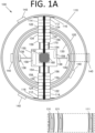
- FIG. 1A is a top view illustrating such a nested-ring cell 100, according to an embodiment of the present invention.
- nested ring cell 100 includes three rings - an outer ring 110, a middle ring 120, and an inner ring 130.
- rings 110, 120 are rails that include movable trams 140 (a.k.a. tractors - see parent U.S. Nonprovisional Patent Application No. 15/655,972 ).
- each ring 110, 120, 130 includes respective electronics 111, 121, 131.
- electronics are included for at least one ring and supplement or replace the functionality of a payload/control section.
- Rails can carry power, data lines, heat (e.g., microheat pipes), and in some embodiments, a propellant fuel line.
- the lines may be hardwired, fiber, and/or 3D printed along or inside the rails, as desired.
- inner ring 130 includes two rotatable nozzles 136 and respective propellant lines 138.
- Propellant lines may be embedded in any desired ring, or more than one ring, without deviating from the scope of the invention.
- Propellant may also be stored within a propellant storage tank (not shown) and may be refilled via a service valve (not shown).
- FIG. 1A shows a nested ring structure that is designed to rotate about one axis (shown as the y-axis here via shaft 170).
- some nested rings rotate about a y-axis shaft, while others rotate about an x-axis shaft perpendicular to the y-axis via a gimbaled mechanism.
- these shafts may not be orthogonal to one another. Indeed, any number of shafts, interconnection therebetween, gimbaling mechanisms, and orientation may be used without deviating from the scope of the invention.
- a payload/control section 150 includes a reaction wheel housing 152 that houses a momentum management system 160.
- Momentum management system 160 controls the net angular momentum vector, and includes reaction wheels (e.g., three-axis reaction wheels) and a momentum dumping system (e.g., magnetorquers) that enable the desaturation of the momentum of the reaction wheels.
- Each nested ring 110, 120, 130 and payload/control section 150 has its own respective motors 112, 122, 132, 156 and can independently rotate. The rotation can be continuous, fixed angular motion that is then stopped, or motion to a prescribed set of angular locations with stops at constant or varying times without deviating from the scope of the invention. Any rotation induced by motors 112, 122, 132, 156 should be countermanded by momentum management system 160 to keep the overall attitude (i.e., a defined observation direction) of nested ring cell 100 steady.
- Motors 112 are attached to outer ring 110 via support structure 116, but are able to rotate about shaft 170 while attached thereto.
- Motors 122 are attached to middle ring 120, but are able to rotate about shaft 170 while attached thereto.
- Motors 132 are attached to inner ring 130, but are able to rotate about shaft 170 while attached thereto.
- motors 156 are attached to payload/control section 150 via tubes/struts 154, but are able to rotate about shaft 170 while attached thereto. All motors 112, 122, 132, 156 in this embodiment have properties currently found in rotation stages with a center hole aperture: (1) bidirectional motion with velocity control; (2) encoders to ensure precise angular motion and positioning; and (3) mechanical clutches to lock.
- Motors 112, 122, 132, 156 are also designed to operate in a vacuum environment. In some embodiments, the motor function can be integrated into shaft 170. In certain embodiments, only one motor per ring is used.
- rings 110, 120, 130 and payload/control section 150 rotate about shaft 170.
- Shaft 170 may also include data and/or power lines that provide data and/or power between rings 110, 120, 130 and payload/control section 150.
- shaft 170 may also contain one or more propellant fuel lines to deliver propellant to one or more rings. This may be used, for instance, to control rotation thereof, as well as to control and power each tram 140 and a sensor or other device that "rides" on top of the tram.
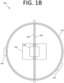
- FIG. 1B is a top cutaway view illustrating a wiring scheme in nested-cell ring 100, according to an embodiment of the present invention.
- the wiring can be traditional metal conductors, optical fiber, 3D printed, pattern transfer fastened/bonded, etc. with interconnects as desired or necessary.
- the wiring may be within the ring, wrapped about the ring, or any combination thereof without deviating from the scope of the invention.
- Various components from FIG. 1A have been removed and colors have been changed to white for illustration purposes. More specifically, ring 120 remains, and the wiring scheme for ring 120 may be similar to that for ring 110 or any other ring that requires power/data for its operation (e.g., to operate trams 140).
- Power lines 180 (lines with larger dashes) and data lines 182 (lines with smaller dashes) extend through shaft 170 and also throughout ring 120. Power line 180 and data line 182 also extend into payload/control section 150 and interface with internal circuitry thereof (not shown). Power and data may be transferred to payload/control section 150 and/or one or more of rings 110, 120, 130 via a direct-contact "brush" and/or non-contact optical, RF, or electromagnetic transport in certain embodiments.
- trams 140 and ring 120 may have a similar structure to that shown in FIGS. 6A and 6B and 5A and 5B, respectively, of parent U.S. Nonprovisional Patent Application No. 15/655,972 , for example.
- trams may be capable of performing various operations, such as connecting to other cells to form a structure, to provide power and/or data and to act as support structures to hold external components that can be articulated (e.g., sensors, cameras, transmitters and/or receivers, mirrors, solar panels, heat shields, mirrors, lenses, etc.), and the like.
- FIG. 1C is a front cutaway view illustrating a generic potential tram 140a that may be capable of performing these operations, according to an embodiment of the present invention.
- Tram 140a includes a linking mechanism 142a that is capable of performing linking operations with linking members of other trams and/or other structures (e.g., holding a component such as a lens, linking with another rail or other physical structure, etc.).
- Control circuitry 144a controls the operation of tram 144a and its components.
- Retaining members 146a keep tram 140a operably connected to or proximate to a rail (not shown), which fits within a rail space 148a defined in part by retaining members 146a.
- Rail space 148a is shown as rectangular in FIG. 1C , but may be any suitable shape without deviating from the scope of the invention.
- Two such trams 140a that are linked via respective linking mechanisms 142a are shown in FIG. 1D .
- tram 140b includes retaining members 141b that hold tram 140b in place on a retaining section of a rail.
- Tram 140b also includes an electromagnet 142b that may engage with magnets of other rings and/or trams.
- mechanical connections may be used in addition to, or in lieu of, magnets.
- Tram 140b also includes wheels 144b that contact the tram retaining section of the rail. Wheels 144b are driven by brushless electric motors 146b via respective shafts 147b. Electrical contacts 148b contact one or more wires of the rail.
- the "wheels" or “guides” can be ball bearings and the motion thereof may be similar to direct-drive, slotless, brushless servomotors.
- the tram in some embodiments may include an optical encoder or other encoder (e.g., a laser-based interferometer) that characterizes the tram position along the rail without deviating from the scope of the invention.
- DDLM direct drive linear motor
- a DDLM is a motor that is laid out flat and directly coupled to the driven load, eliminating the need for ball/lead screws, rack and pinions, belts/pulleys, and gearboxes.
- rails may be coupled to tractors configured as DDLMs.
- the tram and rail can be moved in a similar manner to technology implemented in magnetic levitation (maglev) trains, which induce both motion and levitation using electromagnetics. Motion is induced by altering the polarity of the magnets in sequence and levitation is facilitated by permanent magnets.
- maglev magnetic levitation
- tram 140b includes circuitry 149b that controls operation of tram 140b.
- circuitry 149b may include, but is not limited to, a microcontroller, a transceiver, and/or any other suitable circuitry without deviating from the scope of the invention.
- no control circuitry may be present, and brushless electric motors 146b may be controlled by providing power to the conductor(s) of the rail to drive brushless electric motors 146b.
- tram 140b includes a power contact 150b and a data contact 152b that send/receive power and data, respectively, to/from a connected tram or device.
- tram 140a may power a sensor or camera, receive power from a solar panel or battery, provide power and data between connected cells, etc.
- materials that enable the efficient transfer of heat between connected cells.
- FIG. 1F shows an alternative magnetic tram 140c. Similar to magnetic tram 140b of FIG. 1E , tram 140c includes retaining members 141c, a magnet 142c, and electrical contacts 148c. However, in this embodiment, a motor 146c is powered directly by conductor(s) of the rail and engages with teeth of the rail via gear 144c. Motor 146c rotates gear 144c, moving tram 140c along the rail. Moreover, if a DDLM concept is used, tram 140c in FIG. 1F would not need to include gears 144c or motors 146c. Also similar to tram 140b, tram 140c includes a power contact 150c and a data contact 152c that send/receive power and data, respectively, to/from a connected tram or device.
- tram 140c includes a power contact 150c and a data contact 152c that send/receive power and data, respectively, to/from a connected tram or device.
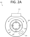
- FIG. 2A is a front cutaway view illustrating a circular magnetic tram 200, according to an embodiment of the present invention.
- Tram 200 includes a linking mechanism 210 that engages with linkage points of other trams (see FIG. 2B , for example).
- Linking mechanism 210 is operably connected to a rotatable collar 220 that rotates about an inner ring 230.
- Control electronics 240 control rotation of rotatable collar 230.
- cells may exchange various physical items and information.
- Such a system linkage interface 400 is shown in FIG. 4 .
- modules i.e., cells
- N and N + 1 connect. After connection, N and N + 1 are able to share power, data, heat, and fuel.
- the layer labeled as "signals test and codex translator” includes sensors, electronics (e.g., circuits), and control systems with software that conducts two functions after successful docking: (1) the layer tests the interconnected signals to ensure that they have the right voltage, current, pulse structure, etc.; and (2) the layer also is able to change the protocol of the data and/or control formats that will pass between modules N and N + 1.
- modules may be manufactured by different vendors and prior worldwide standards generation, communication, and controls may have different protocols (e.g., they may use a different codex).
- the signals test and codex translator layer converts the communication protocols so that modules N and N + 1 can exchange valid information.
- control software may be included in some embodiments at the individual cell level, at the collective ensemble level, or both.
- the collective ensemble represents all of the connected cells and their collective computational abilities in their totality.
- all cells may individually include computation hardware (e.g., microprocessors and/or nanoprocessors, GPUs, etc.).
- Some of the software such as that for a particular cell's self-maintenance functions, could be run on the cells' computational hardware locally.
- "local" (as opposed to global or worldwide) computational cloud architectures may be used. With such an architecture in place, excess computational processing capabilities of cells in the ensemble may be used to support or enable ensemble functions.
- the outer ring dimension can be any desired size, which could depend on the mission and/or launcher that is used.
- the outer ring could be 10cm, 30cm, 300 cm, any desired diameter, or a combination thereof without deviating from the scope of the invention.
- the outer and inner rings are manufactured from carbon fiber reinforced composites (CFSs)
- CFRSs carbon fiber reinforced composites
- rings of approximately 5.7 meters in diameter can readily be produced, which is the same cross section as the fuselage of a Boeing 787 Dreamliner ® .
- the outer ring may have an irregular shape, as discussed herein.
- the nested-ring cell in some embodiments is circular in shape and able to be flattened, it is possible to "stack" cells onto different launch vehicles (e.g., air-launched Pegasus rockets, the Delta rocket family, the SpaceX Falcon 9, etc.).
- launch vehicles e.g., air-launched Pegasus rockets, the Delta rocket family, the SpaceX Falcon 9, etc.
- the outer ring in each cell may have a connector tram that is capable of multi-axis rotation. Consequently, such a joint could be used to connect the stacked nested-ring cells during stowage (see, e.g., FIGS.
- the prehensile grasping mobility of the cells that provides a hop and/or roll action in some embodiments requires more power than body-mounted solar cells of conventional CubeSats can provide.
- Space data from Aerocubes show that a 1U CubeSat with solar cells mounted on two sides is capable of producing approximately 4 watts of power for normal orbits and operations.
- calculations show that approximately 8 watts of power would be necessary to have a fully functioning programmable cell in some embodiments, albeit that number is based on power draws of current motors and robotics. Gathering more solar power generally requires a deployable (i.e., a solar panel that extends out from the cell). This approach is the current practice in space systems.
- a traditional solar panel deployable would be obstructive.
- a deployable that can be opened/closed repeatedly, as is described further in some embodiments below.
- This may be risky using folding deployable solar panels (e.g., origami-type structures) due to the complex mechanical linkages involved therein, and the possibility of a jam-up.
- two or more round solar panels may be employed.
- the backs of the solar panels may carry batteries that can scale with the solar panel surface area and create a more integrated photovoltaic system.
- the batteries may make up the surface area of the top and bottom of the cell, and thus protect the delicate solar panel surface area from handling damage.
- solar cells/batteries within a panel may be attached to trams on the outer ring, and thus can both traverse along the outer ring and pivot about a universal motion joint of the tram.
- the specialized connections may push the solar cell/battery panels above the outer ring to allow the solar cell/battery panels to pivot and rotate about the connections and deploy, in a similar manner to what is shown in FIGS. 7B and 7C .
- the specialized connections may be motorized such that upon failure of a solar cell/battery panel or upon the cell instituting a roll motion (e.g., via prehensile grasping), the solar cell/battery panels can be rotated back into the housing.
- the diameter of the solar cell/battery panels should be smaller than the diameter of the outer ring to permit protective stowage.
- the solar cells are typically hidden, and the specialized connections may have a robotic joint design to enable both twisting and pivoting motion.
- mm-Wave technology Ka, V, W, mm
- ⁇ Wave technology and in the future, terahertz technology and beyond
- S, C, X, Ku, and K bands current wireless technology
- the mm waves and microwaves are more directional, and therefore, it is easier to direct the energy toward the payload/control section.
- Another feature that is possible is that when multiple cameras are mounted on ring trams, it is possible to see in front, to the side, and behind the facing direction of the nested ring structure.
- Cameras on an inner ring can be controlled to periodically "look around” (e.g., look other directions including towards an adjacent connected neighbor cell) without having to rotate the payload/control section.
- a small light detection and ranging (LIDAR) device (which, in essence, is laser radar) can be attached to a tram that is powered by the payload section.
- the laser and its smaller extendable telescope (if necessary) and/or a beam directing mirror may be used to allow sensing of nearby objects (e.g., ⁇ 300km or less) to mitigate against a hit by space debris.
- Certain payloads can only be operated when extended.
- the laws of optics dictate the distance between lenses and mirrors for the desired magnification/resolution. Extensible systems such as telescopes cannot easily be "flat-packed".
- a primary lens or mirror on one of the rings may be rotated out such that the lens or mirror is at a particular distance L from a secondary mirror (located on another ring or on the payload/control section).
- an antenna e.g., RF, mm-Wave, ⁇ Wave, etc.
- a similar concept can be applied with other optical elements that are typically found in telescopes to filter or analyze light prior to detection by a sensor.
- the optical focal point is not placed on the sensor or a secondary mirror. Rather, the focal point is just above the sensor or secondary mirror. This allows insertion of spatial filters (e.g., a field stop) and other devices to be placed at the focal point to further refine and characterize the image.
- the characterization sensors or devices may be placed on a tram closer to the sensor (often, but not necessarily, on the payload/controller section). Given the multiple nested rings of some embodiments, it is also possible to change the magnification of the lens/mirror of the primary optics, and consequently allow for multiple telescopic magnifications.
- a lens of aperture D may be rotated such that the distance from the lens to the surface (e.g., a camera chip) has distance L .
- a lens or a mirror may direct the focused light onto a second mirror, which then further reflects the light to a sensor located on a rail or the payload/control section. This would be useful, for example, if there are multiple cameras and each camera chip is sensitive to a different wavelength band.
- the senor may need to be shielded from ambient light to keep it cool, and thus lower electronics noise.
- Such embodiments may capture images from a source that emits heat via radiation (e.g., the Earth).
- the Earth's albedo produces sufficient energy to increase the noise level on sensitive sensors.
- these sensors must be kept cold by using cryogenic fluids, which evaporate in the vacuum of space over time, thus rendering the sensor inoperable. In orbits about Earth, staring into dark space can lower the surface temperature of an object close to 116K (-157°C).
- sensitive sensors can be placed so as not to look at the sun or Earth, and the image (i.e., desired incoming radiation) may be guided to the sensor via a sequence of mirrors that can move with motion of the cell in orbit.
- Another approach would be to use sun or heat shields to protect a sensor in a similar configuration to the deployable solar panels described below. The sun and heat shields may thus fold out and be positioned as desired.
- the divergence of the laser beam may be changed by using mirrors or lenses from different nested ring deployables.
- Other scenarios are also possible in which cells are attached, and the totality of all of the linked cells takes up a distance measured in kilometers. In such instances, a high speed local optical free-space intracell communication link may be established. To better appreciate the advantages of this scenario consider 1,000 attached cells in some articulated topology with Cell #1 and Cell #1000 being at opposite ends. It may be more efficient (e.g., reduced latency in information transfer) for Cell #1 and Cell #1000 to communicate via a direct free-space optical communication link than via a woven hardwire communication system.
- a nested-ring system may be beneficial in the assembly of caged structures that carry radiative matter, such as a radioisotope thermoelectric generator (RTG or RITG) or a nuclear reactor.
- RTG radioisotope thermoelectric generator
- RITG nuclear reactor
- a nuclear reactor may serve as power sources for long duration space missions, such as to the edges of our solar system and beyond.
- a drawback of such nuclear systems is that the radiation emitted from these devices is harmful to the operation of nearby electronics.
- RTGs these are typically placed at the end of a large truss.
- an RTG or nuclear reactor may be placed in the center of a structure.
- reactors serve not only to provide power, but also heat given that temperatures on conventional electronics usually plummet below the operational range.
- a large cage structure for instance, where operating payloads are placed at the periphery and the power source is in the middle, would be able to deliver electrical power and heat from the center core to other cells via diffusion through interconnected cells and/or via radiative transfer if the payload/control sections of the respective cells are oriented to capture the heat.
- the reactor portion in the center is a sphere (e.g., one-meter diameter)
- Stefan-Boltzmann's Law approximately 6.3 kW of radiated heat power is emitted via radioactive decay if the center temperature can be held at 200°C. Rather than having all the heat escape into space, a portion could be collected by orienting the payload/control sections of the cells.
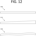
- the nested ring structures may be collapsible and stackable for launch. Such embodiments may facilitate more efficient use of the payload compartment volume of a launch vehicle, for example. Because current space systems do not yet utilize "cell-based" architectures, efficient packaging for launch is problematic for these systems. At certain sizes, not all shapes lead to efficient stowage. For example, prismatic shapes, such as cubes (e.g., CubeSats), do not efficiently pack within a cylindrical launch vehicle when launched in large numbers. Some embodiments offer a better solution. One or more stacks of nested ring cells could efficiently fill the launch vehicle payload volume with more space vehicles. Also, nested ring cells could be designed to fit to the payload shape and volume of a given launch vehicle (e.g., that of FIG. 2B ).
- cubes e.g., CubeSats
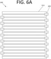
- FIG. 6A is a side view illustrating a cell stack 600 in a stowed configuration, according to an embodiment of the present invention.
- Cell stack 600 includes ring-shaped cells 610, where each cell is connected to two other cells (unless on the top or bottom of cell stack 600, in which case the top and bottom cells are connected to only one other cell) via connecting members 620 (e.g., ball joint connectors, magnets, or any other suitable connector without deviating from the scope of the invention).
- cell 610 may be cell 100 of FIGS. 1A and 1B .
- each connecting member 620 is on the opposite side of cell stack 600 as the one above/below it.
- connecting members may interconnect adjacent cells in any desired location and/or configuration without deviating from the scope of the invention.
- connecting member 620 may rotatably connect two adjacent cells such that they are not separable. However, in certain embodiments, connecting member 620 may be made up of two separate portions - one for each connected cell - that mechanically and/or magnetically connect to, and release from, one another.
- the cells may mechanically interlock with one another via a releasable mechanism driven by an actuator.
- some cells may use magnets to interlock and others may use mechanical interlocking mechanisms. Mechanical interlocking mechanisms may be stronger and may support larger structures.
- mechanically connected cells may form a support structure within the space system that supports other cells or non-cell space vehicles and provides the ability to build even larger space systems than magnets alone may allow. Additionally or alternatively, such structures may be used for terrestrial and/or underwater support structures in some embodiments.
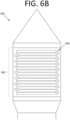
- FIG. 6B is a side view illustrating a payload section 632 of a launch vehicle 630 with cell stack 600 loaded therein, according to an embodiment of the present invention. Due to the generally cylindrical shape of payload section 632 in this embodiment, cell stack 600 makes efficient use of the space therein.
- cells 610 may require considerably less volume than a 1.5U or 3U CubeSat, for example. As such, a larger number of flattened cells capable of performing equivalent or superior functionality to small CubeSats may be deployed in a single launch.
- cells may be inserted in multiple launches and may collectively join to form larger structures than fixed-size systems that conventional launch vehicles can deliver. This enables construction of potentially enormous structures in space.
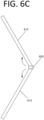
- FIG. 6C is a side view illustrating two cells 610 unfolding about a common connection member 620, according to an embodiment of the present invention.
- cells 610 may deploy about their respective connection mechanisms.
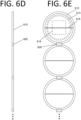
- cells 620 move about connection mechanism 620 until they are perpendicular with respect to their stowed position. See also FIG. 6D .
- connection member 620 may employ a variable angle connection scheme, the full deployment need not be as shown in FIGS. 6D and 6E .
- the net expanded or unfolded structure can have a curved shape to enable capture of light or images with better efficiency, for example.
- FIG. 6E is a front view illustrating cell stack 600 in the deployed configuration, according to an embodiment of the present invention.
- Cells 610 include an outer ring 612 that defines the widest circumferential boundary of cells 610 and a support member 616 to which one or more inner rings and a payload may be attached. As shown in the upper cell, at least one inner ring 614 and a payload/control section 618 may be attached. While shown as a thick line here, it should be appreciated that support member 616 may be hollow in some embodiments, and may internally and/or externally facilitate power and/or data between rings 612/614 themselves, and/or between rings 612/614 and payload/control section 618.
- any suitable support structure, or structures may be used without deviating from the scope of the invention.
- multiple support structures may be used.
- adjacent cell sections may be connected to one another.
- outer ring 612 may be connected to inner ring 614
- inner ring 614 may be connected to payload/control section 618, etc.
- Various components may be included in and/or on payload/control section 618. Essentially, these components may be the subsystems that are required to control and fly space vehicles. These may be any suitable component including, but not limited to, cameras, radio frequency (RF) antennas, transceivers, thermometers, radiation detectors, novel sensors, light sources, spectrometers, reaction wheels, an attitude determination and control system (ADCS), processing circuitry (e.g., a central processing unit (CPU), a field programmable gate array (FPGA), an accelerator (e.g., a graphical processing unit (GPU)), etc.), propulsion mechanisms and tanks, or any other component or combination of components without deviating from the scope of the invention.
- One or more components may be deployable in some embodiments. For instance, an antenna may be extended and retracted, a solar array may be unfurled and retracted, etc.
- some connected nested-ring cells do not contain a payload/control section, such as payload/control section 618, but instead only have nested rings (i.e., they are hollow in the center).
- These specialized nested-ring cells may be wirelessly controlled from adjoining nested-ring cells that have a full complement of control systems.
- cells without a payload/control section may have electronics and batteries within their rings, or attached thereto, that enable them to move their trams and rings.
- FIGS. 6A-E shows a cell stack that deploys into a linear arrangement of cells.
- any cell interconnection patterns are possible without deviating from the scope of the invention.
- the cells may move about one another, connecting to, moving to the outer rim, and disconnecting from one another using a suitable connection mechanism (e.g., magnets, as shown in FIGS. 7A and 7B of parent U.S. Nonprovisional Patent Application No. 15/655,972 ).
- FIG. 7A is a side view illustrating a cell 700 in a partially deployed configuration with round top and bottom solar panels 720, 730, respectively, according to an embodiment of the present invention.
- Sun or heat shields, reflecting surfaces, or an antenna dish may be designed and deployed in a similar manner to solar panels 720, 730 in some embodiments.
- Solar panels 720, 730 may be thin film, crystalline, or any other suitable solar panel technology without deviating from the scope of the invention.
- Top solar panel 720 and bottom solar panel 730 connect to a cell body 710 of the cell via extensible, rotatable connecting members 722, 732, respectively.
- solar panels may be connected to trams on rings of the cell.
- Respective actuators 724, 734 rotate each of connecting members 722, 732.
- the rotatable actuators may be on the side of connecting members 722, 732 proximate to the respective solar panels, the side proximate to cell body 710, or both.
- solar panels 720, 730 are housed or recessed within cell body 710. Consequently, if fully stowed in this side view, solar panels 720, 730 would not be visible.
- connecting members 722, 732 push solar panels 720, 730 above/below cell body 710, respectively, via actuators 724, 734.
- Solar panels 720, 730 can then pivot and rotate about connecting members 722, 732 and deploy, as shown in FIGS. 7B and 7C .
- connecting members 720, 730 are also hinged such that solar panels 720, 730 may also be rotated about an axis provided by the hinge.
- Connecting members 720, 730 include power lines (not shown) that provide power from solar panels 720, 730 to cell 700.
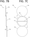
- FIGS. 7B and 7C are side and front views, respectively, illustrating cell 700 in a deployed configuration, according to an embodiment of the present invention.
- solar panels 720, 730 first pop up (i.e., above cell body 710 such that they clear its thickness) and then rotate about respective rotatable connecting members 722, 732 to expose photovoltaic cells (not shown) of solar panels 720, 730.
- Rotatable connecting members 722, 732 are also connected to an outer ring 712 of cell body 710.
- a support member 714 is also included in this embodiment. The orientation, shape, size, and configuration of support member 714 may differ from what is shown without deviating from the scope of the invention.
- the diameter of solar panels 720, 730 should be smaller than the diameter of cell body 710 to permit protective stowage.
- respective connecting members have a robotic joint design to facilitate twisting and pivoting maneuvers.
- solar panels 720, 730 may both have their photovoltaic cells facing the same direction (e.g., both on the face visible in FIG. 7C ).
- batteries may be included opposite the photovoltaic side of the solar panels in order to facilitate compactness and to increase power storage capabilities.
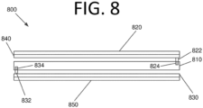
- FIG. 8 Such a cell 800 is shown in FIG. 8 in a partially deployed configuration. Like cell 700 of FIGS. 7A-C , cell 800 includes a cell body 810, a top solar panel 820, a bottom solar panel 830, extensible, rotatable connecting members 822, 832, and actuators 824, 834.
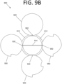
- Solar panels 920, 930, 940, 950 are stacked on top of outer ring 912.
- the panels need not be all solar panels in some embodiments. Rather, at least one panel could be another mission support structure, such as reflecting (RF or optical) surfaces for enabling satellite cross-link communications or power transfer (e.g. microwave).
- solar panels 930, 940, 950 have different shapes than solar panel 920, which is in top and does not need to accommodate for any rotatable connection members. More specifically, the shape of solar panel 930 accommodates rotatable connection member 922, the shape of solar panel 940 accommodates rotatable connection members 922, 932, and the shape of solar panel 950 accommodates rotatable connection members 922, 932, 942. It should be noted that the shapes of solar panels 930, 940, 950 as depicted are not necessarily optimal, and any suitable shape may be used without deviating from the scope of the invention.
- solar panels in some embodiments may deploy via hinges.
- the hinges may be connected to a tram on the outer ring that can move.
- the panel is an antenna or reflector that must face in a particular direction.
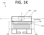
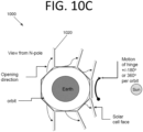
- FIGS. 10A and 10B An example cell 1000 of an embodiment with a solar panel is shown in FIGS. 10A and 10B .
- Cell 1000 includes a cell body 1010, a solar panel 1020, and an actuated hinge 1030.
- Actuated hinge 1030 rides on a tram (not shown) that can go move around the perimeter of the outer ring.
- Actuated hinge 1030 includes a post 1032 that is operably connected to cell body 1010, an actuator 1034, and a solar panel connection plate 1036 that is operably connected to actuator 1034 and facilitates hinge functionality for solar panel 1020.
- solar panel 1020 may be connected directly to actuator 1034 without deviating from the scope of the invention.
- hinge 1030 may be movable about the outer ring of cell 1000 in a manner similar to that disclosed in parent U.S. Nonprovisional Patent Application No. 15/655,972 .
- actuator 1034 causes solar panel 1020 to rotate as shown in FIG. 10B .
- Actuated hinge 1030 coupled with tram motion about the outer ring permits the photovoltaic face of solar panel 1020 in this embodiment to face the sun when orbiting the Earth.
- the photovoltaic face of solar panel 1020 would also be facing up with respect to FIGS. 10A and 10B , but may be tilted in order to be better oriented towards the sun.
- hinge 1030 may be constructed such that solar panel 1020 can rotate all the way to the back side of cell body 1010 such that the surface of solar panel 1020 that faces towards the top of cell body 1010 is facing outwards (down with respect to FIG. 10A ) from the back of cell body 1010.
- FIG. 10C illustrates potential orientations of solar panel 1020 during orbit, according to an embodiment of the present invention. Only solar panel 1020 is shown in FIG. 10C for illustration purposes. As cell 1000 orbits the Earth, the optimal orientation for solar cell 1020 changes. Hinge 1030 may be used to optimally orient solar panel 1020 towards the sun (except perhaps in eclipse, if the orbit has an eclipse phase). Alternatively, solar panel 1020 could be an antenna, a reflector, or any other device or structure that requires pointing in a specific direction without deviating from the scope of the invention. Moreover, multiple hinges may be included enabling more complex articulation, and/or panels may rotate.
- sun shields or heat shields may be included and deployed in a similar manner to the solar panel configurations shown in FIGS. 7A , 7B , 9A-C, 10A, and 10B.
- the sun shields or heat shields may take the place of one or more of the solar panels.
- FIGS. 6C-10C There are some missions in which a deployable system such as that shown in FIGS. 6C-10C may not provide the necessary functionality.
- a very large aperture telescope is one example.
- a large antenna is another. Accordingly, some embodiments have an alternative design that enables such missions.
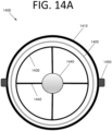
- Contact points 1450 have a prehensile grasp function, allowing a single contact point 1450 to grasp, be movable, and be rotatable, as in or similar to a ball-in-socket joint with a lock-clutch.
- the motion of contact point 1450 is controlled under motorized actuation control.
- FIG. 14B shows a side view of telescope 1400.
- telescope 1400 also includes a lower portion with prehensile contact points 1450, an outer ring 1460, an inner ring 1470, a light sensor 1480, and light sensor supports 1482.
- Other components, such as light shields, light test instrumentation, etc. may be included in some embodiments.
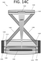
- FIG. 14C shows telescope 1400 when deployed.
- Lens support ring 1430 is extended via extension arms 1490.
- Extension arms 1490 may be controlled to place lens 1440 the desired distance from sensor 1480 in order to properly focus light.
- the received light may then be converted by sensor 1480 into analog, and then digital, electronic signals, which may then be processed by electronics (not shown) of telescope 1400.
- Additional mirrors may be used without deviating from the scope of the invention, and different configurations, such as a Schmidt-Cassegrain architecture, are also possible. Indeed, various such telescopes with different properties interconnected at prehensile contact points 1450 are possible without deviating from the scope of the invention. Due to the movable properties of contact points 1450, telescopes of some embodiments can be facing in one direction while others face in different directions.
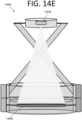
- FIG. 14D illustrates a cell-based extensible/collapsible telescope 1400a similar to that of FIGS. 14A-C , except that telescope 1400a includes two reflecting mirrors 1440a, 1480a.
- primary (larger) reflecting mirror 1480a has a hole in the middle (not shown) that houses sensors (e.g., photodetectors).
- Sensor e.g., photodetectors
- Light striking mirror 1480a is focused and reflected onto mirror 1440a, which is then further focused and reflected through the hole onto the sensors.
- Components of telescope 1400a are otherwise similar to telescope 1400.
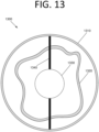
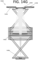
- FIG. 14F A more extended version of an energy harvesting device 1400c is shown in FIG. 14F .
- energy harvesting device 1400c includes three attached rings, of which the top and bottom can expand.
- the center ring has a large reflector or energy harvesting surface 1480c, which has a hole (not visible).
- the top supported structure includes an energy harvesting reflector 1440c that captures the focused energy from reflector or energy harvesting surface 1480c
- the bottom structure includes a sensor 1495c (e.g., a photodetector).
- connections similar to 922, 932, 942, 952 of FIG. 9 would allow the unused reflectors 1440d to be dropped down along the extension arms shown here (similar to extension arms 1490 of FIG. 14C ) so that maximum energy or light could be harvested by reflector 1480d.
- Energy harvesting device 1400d has a variable f-number, which is tantamount to a variable depth of field or resolution.
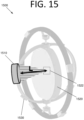
- a lens/mirror may be deployed on a tram in order to provide additional telescope functionality.
- a cell 1500 is shown in FIG. 15 .
- Telescope 1500 accommodates the need for an optical element (here, lens/mirror 1510) to be located at a precise distance from a component, such as a photodetector 1522 of payload control section 1520.
- Lens/mirror 1510 moves about its respective ring via a tram 1530.
- the specific tram 1530 that carries lens/mirror 1510 is obscured in this view.
- Lens/mirror 1510 on a movable tram 1530 can be a light shield, an RF collector, or any other device or structure that requires physical separation and precise distance separation without deviating from the scope of the invention.
- Some embodiments may also be used to reduce noise in an optical and/or RF detector.
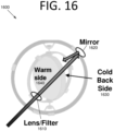
- a cell 1600 is shown in FIG. 16 .
- a lens 1610 and a mirror 1620 with possible optical or RF filters/polarizers are employed to guide the incoming energy onto a side of the cell that is colder (e.g., cold side 1630) and holds a sensor (not visible). In this manner detection may occur on cold side 1630 rather than on warm side 1640, which may have more noise, be warm enough to damage the sensor, etc.
- a similar embodiment to that shown in FIG. 16 could be used to guide light or RF that is leaving the cell as (i.e., optical or RF reciprocity). In this example, the light or RF leaving the cell may come out from the warmer side in some embodiments.
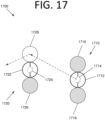
- System 1700 includes a laser-emitting cell 1710 and a reflecting cell 1720.
- Laser-emitting cell includes a cell body 1712, a payload/control section 1714 that includes a laser, and two solar panels 1716.
- Reflecting cell 1720 includes a cell body 1722, a payload/control section 1724, a solar panel 1726, and a mirror 1728.
- Laser light emitted by payload control section 1714 is oriented towards mirror (or RF reflector) 1728.
- Mirror 1728 is oriented towards a target (e.g., a cell with another mirror, another space vehicle, a cell with a receiver, a ground station on Earth, etc.). In this manner, rapid intra-cell and external communications can be provided.
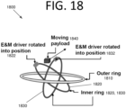
- the cell ensemble may have a large size (e.g., 1 km diameter or more). It may be desirable to move payloads (e.g., propellant, batteries, sensors, just mass, etc.) along the structure to mount it to a cell, or move it to a different cell.
- payloads e.g., propellant, batteries, sensors, just mass, etc.
- FIG. 18 A cell 1800 for this purpose is shown in FIG. 18 .
- Cell 1800 includes an outer ring 1810 and two inner rings 1820, 1830. Which inner ring is inside the other is a matter of design choice.
- outer ring 1810 encompasses inner rings 1820, 1830, which are oriented to some angle with respect to one another and outer ring 1810.
- E&M driver 1822 and E&M driver 1832 briefly turn off their magnetic attraction, and as the payload 1840 begins to exit the cross-ring structure, both E&M driver 1822 and E&M driver 1832 generate a field that repels payload 1840.
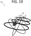
- This operation sequence when exercised in a concatenated fashion along multiple connected rings (see FIG. 19 , for example), will produce motion of payload 1840.
- payload 1840 must itself be magnetic or must be in a magnetic container; and (2) another ring (not shown) or the payload/control section (not shown) provides a sequence of electromagnetic fields that maintain payload 1840 within the cross-ring structure of rings 1810, 1820, 1830.
- Multiple cells may form a virtual "rail" system that moves a payload along an electromagnetic "trap” by sequential electromagnetic actuation.
- a space cell-based conveyor belt system 1900 is shown in FIG. 19 .
- the payload is moved along the line of the gray arrow.
- a similar approach may be employed for terrestrial or underwater conveyor belt applications.
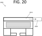
- FIG. 20 is a front cutaway view illustrating a tram 2000 configured to be used in a mass-conveyor belt system, according to an embodiment of the present invention.
- tram 2000 includes a magnet housing 2010 and electromagnets 2020 that are extendible outward from within magnet housing 2010.
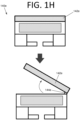
- electromagnets may be located on the left side of the top of the tram and be deployable via a hinge in a flip-out fashion, similar to the mechanism shown in FIG. 1H .
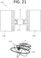
- Electromagnets 2020 alternate in polarity from north to south, as is better seen in FIG. 21 . As a payload moves past magnets 2020, the polarities switch in a manner similar to a maglev train, driving the payload onward in conjunction with other electromagnets of other trams.
- FIG. 21 illustrates a system 2100 for movement of a payload 2110 with respect to two trams 2120, 2130, according to an embodiment of the present invention.
- electromagnets of each tram 2120, 2130 have alternating polarities.
- Payload 2110 also has its own magnets (permanent or electromagnetic), the polarities of which may stay the same in some embodiments.
- the lower diagram shows the positions of trams 2120, 2130 during movement of payload 2110 in this example.
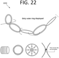
- the concept of the prehensile grasp (or joint) as described above also enables a global twisting motion, which is shown in the top image of FIG. 22 , without worrying about edge-contact since by fiat, the curvature about the contact point will always be away from the contact point.
- FIG. 23 A caged structure 2300 that does so with respect to the outer cells is shown in FIG. 23 .
- Cell 2310 includes a space-rated nuclear reactor and is located at the center of the cage.
- Cells 2320 surround cell 2310 in a "boxed X" pattern. In this manner, cells at the outside of the cage may be kept some distance from cell 2310. Power and/or heat may be provided by cell 2310 to cells 2320.
- FIG. 24 is an architectural diagram illustrating a sparse aperture array 2400, according to an embodiment of the present invention.
- Sparse aperture array 2400 uses the configuration described with respect to FIG. 9B .
- seven cells 2430 include respective shafts 2460 (other nested cells and components not shown) that are connected (connections not shown) in a specific orientation defined in the literature as the Golay-9 array. See, for example, M. J. E. Golay, "Point Arrays Having Compact, Nonredundant Autocorrelations," J. Opt. Soc. America, Vol. 61, Issue 2, pp. 272-273 (1971 ).
- the Golay-9 refers to nine apertures 2440 that have rotated into the array shape shown using rotated connecting members 2450.
- Sparse aperture technology enables the use of many smaller apertures to arrive at a sensor (optical, microwave, RF, etc.) resolution that is given by a much larger aperture.
- Use of smaller apertures is beneficial at least because physically larger apertures are typically more difficult to manufacture and deploy.
- the Golay-9 is discussed by way of example only, and other sparse array distributions may be used without deviating from the scope of the invention.
- connection strength needs to be stronger than in space.
- a connection can be provided in some embodiments that can move, but then has a strong locking feature.
- a tower to be built from connected rings should be designed to deploy from a stowed configuration (see FIG. 6A , for example) to an expanded configuration (see FIG.
- the bottom ring can support the weight of all of the above-connected rings.
- a structure may not be as practical as interconnected nested rings that form a truss structure (e.g., a deck, pony, or through truss, which is nomenclature used in bridge-forming technology).
- the strength requirement for each ring is reduced because the load bearing is shared, and so are the interconnections.
- Applications are also possible in some embodiments where the outer ring(s) are not circular, but rather triangular, square, or any other desired shape. Within this shape, one could also have nested ring structures, depending on the application.
- the materials that make up the cells for underwater applications should also be water-compatible (for instance, able to resist corrosion in salt water).
- the outer ring in the nested ring structure could be made of a tubular material filled with air. The desired structure of connected nested rings may then be articulated or assembled on the water surface, and by removing the air and/or filling with water, it can be sunk to the desired depth.
- a variant of this idea includes overall structure designs that allow the major structure to have some buoyancy, and by a combination of partially removing or adding air or water in the ring tubes and/or changing the structure shape (via motion along the joints/trams, for instance), the buoyancy can be varied, thereby enabling structures to be moved up and down through a column of water (Archimedes principle).
- an open cage structure such as that in FIG. 23
- a collapsed structure such as that in FIG. 6A
- sink could be made to sink.
Landscapes
- Engineering & Computer Science (AREA)
- Remote Sensing (AREA)
- Aviation & Aerospace Engineering (AREA)
- Chemical & Material Sciences (AREA)
- Combustion & Propulsion (AREA)
- Radar, Positioning & Navigation (AREA)
- General Physics & Mathematics (AREA)
- Sustainable Development (AREA)
- Physics & Mathematics (AREA)
- Astronomy & Astrophysics (AREA)
- Life Sciences & Earth Sciences (AREA)
- Photovoltaic Devices (AREA)
- Arrangements For Transmission Of Measured Signals (AREA)
- Filling Or Discharging Of Gas Storage Vessels (AREA)
- Artificial Fish Reefs (AREA)
- Telescopes (AREA)
- Prostheses (AREA)
- Pharmaceuticals Containing Other Organic And Inorganic Compounds (AREA)
- Finger-Pressure Massage (AREA)
- Apparatus Associated With Microorganisms And Enzymes (AREA)
Applications Claiming Priority (4)
| Application Number | Priority Date | Filing Date | Title |
|---|---|---|---|
| US15/655,972 US11643225B2 (en) | 2017-07-21 | 2017-07-21 | Interlocking, reconfigurable, reconstitutable, reformable cell-based space system |
| US15/945,617 US11155366B2 (en) | 2017-07-21 | 2018-04-04 | Interlocking, reconfigurable, reconstitutable, reformable cell-based system with nested ring structures |
| PCT/US2018/037655 WO2019018086A1 (en) | 2017-07-21 | 2018-06-14 | SYSTEM FOR REFORMABLE, RECONSTITUTEABLE, RECONFIGURABLE CELLS WITH MUTUAL LOCKING WITH UNBINED RING STRUCTURES |
| EP18836031.7A EP3655325B1 (de) | 2017-07-21 | 2018-06-14 | Ineinandergreifendes, rekonfigurierbares, rekonstituierbares, reformbares zellbasiertes system mit verschachtelten ringstrukturen |
Related Parent Applications (2)
| Application Number | Title | Priority Date | Filing Date |
|---|---|---|---|
| EP18836031.7A Division EP3655325B1 (de) | 2017-07-21 | 2018-06-14 | Ineinandergreifendes, rekonfigurierbares, rekonstituierbares, reformbares zellbasiertes system mit verschachtelten ringstrukturen |
| EP18836031.7A Division-Into EP3655325B1 (de) | 2017-07-21 | 2018-06-14 | Ineinandergreifendes, rekonfigurierbares, rekonstituierbares, reformbares zellbasiertes system mit verschachtelten ringstrukturen |
Publications (2)
| Publication Number | Publication Date |
|---|---|
| EP4450402A2 true EP4450402A2 (de) | 2024-10-23 |
| EP4450402A3 EP4450402A3 (de) | 2024-12-25 |
Family
ID=65014525
Family Applications (2)
| Application Number | Title | Priority Date | Filing Date |
|---|---|---|---|
| EP18836031.7A Active EP3655325B1 (de) | 2017-07-21 | 2018-06-14 | Ineinandergreifendes, rekonfigurierbares, rekonstituierbares, reformbares zellbasiertes system mit verschachtelten ringstrukturen |
| EP24195038.5A Pending EP4450402A3 (de) | 2017-07-21 | 2018-06-14 | Ineinandergreifendes, rekonfigurierbares, rekonstituierbares, reformbares zellbasiertes system mit verschachtelten ringstrukturen |
Family Applications Before (1)
| Application Number | Title | Priority Date | Filing Date |
|---|---|---|---|
| EP18836031.7A Active EP3655325B1 (de) | 2017-07-21 | 2018-06-14 | Ineinandergreifendes, rekonfigurierbares, rekonstituierbares, reformbares zellbasiertes system mit verschachtelten ringstrukturen |
Country Status (7)
| Country | Link |
|---|---|
| US (1) | US11155366B2 (de) |
| EP (2) | EP3655325B1 (de) |
| JP (1) | JP7137621B2 (de) |
| AU (1) | AU2018303552B2 (de) |
| CA (2) | CA3206759A1 (de) |
| NZ (1) | NZ760993A (de) |
| WO (1) | WO2019018086A1 (de) |
Families Citing this family (19)
| Publication number | Priority date | Publication date | Assignee | Title |
|---|---|---|---|---|
| CN110450987A (zh) * | 2019-08-14 | 2019-11-15 | 上海卫星工程研究所 | 航天器舱段间的电磁吸附装置及其制作方法 |
| US11878816B2 (en) * | 2019-09-20 | 2024-01-23 | Scott Weintraub | Reusable modular spacecraft and related systems |
| CN111572823B (zh) * | 2020-05-29 | 2021-11-02 | 湖南国防工业职业技术学院 | 一种用于卫星舱抓捕的抱合装置 |
| US11492147B2 (en) * | 2020-07-30 | 2022-11-08 | The Aerospace Corporation | Stackable satellite structure and deployment method |
| US11990671B2 (en) * | 2020-08-14 | 2024-05-21 | M.M.A. Design, LLC | Deployable electromagnetic radiation directing surface system with actuators |
| WO2022186872A2 (en) * | 2020-12-10 | 2022-09-09 | Zero-G Horizons Technologies, Llc | Rotational technologies for space infrastructure |
| US11738891B1 (en) * | 2020-12-30 | 2023-08-29 | United States Of America As Represented By The Administrator Of Nasa | Modular artificial-gravity orbital refinery spacecraft |
| EP4147980A1 (de) * | 2021-09-13 | 2023-03-15 | BAE SYSTEMS plc | Schild für eine waffe mit gerichteter energie |
| WO2023037092A1 (en) * | 2021-09-13 | 2023-03-16 | Bae Systems Plc | Directed-energy weapon shield |
| US12354777B2 (en) * | 2021-10-04 | 2025-07-08 | The Aerospace Corporation | Integrated electro-magnetically preloaded kinematic joint for on-orbit assembly of modular space vehicles |
| US12509252B2 (en) * | 2021-11-17 | 2025-12-30 | Outpost Technologies Corporation | Space vehicles with paraglider re-entry, and associated systems and methods |
| DE102022111501B3 (de) * | 2022-05-09 | 2023-06-29 | Sascha Larch | Antriebsstufe einer Trägerrakete, Trägerrakete und Verfahren zum Steuern einer Antriebsstufe |
| US20240039077A1 (en) * | 2022-07-28 | 2024-02-01 | The Aerospace Corporation | Energy storage radiators |
| CN115331853B (zh) * | 2022-08-31 | 2025-01-28 | 一重集团大连工程技术有限公司 | 一种核反应堆屏蔽运输装置 |
| WO2024248606A1 (en) * | 2023-05-30 | 2024-12-05 | Universiteit Twente | Method and system for controlling an angular orientation of a spinning body |
| NL2034951B1 (en) * | 2023-05-30 | 2024-12-10 | Univ Twente | Method and system for controlling an angular orientation of a spinning body |
| FR3149873A1 (fr) * | 2023-06-15 | 2024-12-20 | Thales | Système d'attache d'un satellite |
| US12497195B2 (en) * | 2023-10-12 | 2025-12-16 | United States Of America As Represented By The Secretary Of The Air Force | Articulating spacecraft chassis |
| WO2026000009A1 (de) * | 2024-06-27 | 2026-01-02 | Weinmann Eichinger Lili | Modulares satellitensystem |
Family Cites Families (33)
| Publication number | Priority date | Publication date | Assignee | Title |
|---|---|---|---|---|
| US3169725A (en) | 1962-05-24 | 1965-02-16 | Rene A Berglund | Erectable modular space station |
| US3785590A (en) | 1970-12-21 | 1974-01-15 | Communications Satellite Corp | Spacecraft body with roller mechanism for deployable-retractable thin film solar array |
| US3744739A (en) | 1972-04-12 | 1973-07-10 | Nasa | Multiple in-line docking capability for rotating space stations |
| US4715566A (en) | 1985-10-29 | 1987-12-29 | Martin Marietta Corporation | Interconnectable space station module and space station formed therewith |
| US4917215A (en) | 1988-08-23 | 1990-04-17 | Grumman Aerospace Corporation | Space station transport system for extravehicular activity |
| US5104070A (en) | 1989-06-01 | 1992-04-14 | Space Industries, Inc. | Structural latch for vehicle coupling mechanisms |
| US5017820A (en) | 1990-04-23 | 1991-05-21 | Rockwell International Corporation | Piezoelectric rotary union system |
| EP0541052B1 (de) | 1991-11-05 | 1996-02-07 | Hitachi, Ltd. | System von Raumfahrzeugen |
| JPH05330500A (ja) | 1992-06-03 | 1993-12-14 | Toshiba Corp | 宇宙航行体の分離結合装置 |
| US5305970A (en) | 1993-01-12 | 1994-04-26 | General Dynamics Corporation, Space Systems Division | Centrifugal space propellant storage and transfer depot |
| US5580013A (en) | 1994-12-20 | 1996-12-03 | Velke; William H. | Economical construction and assembly method for a modular permanent orbiting space station |
| AU1626000A (en) | 1998-11-18 | 2000-06-05 | Larson International, Inc. | Amusement ride without hubs and spokes |
| US6536712B1 (en) | 1999-07-22 | 2003-03-25 | Lockhead Martin Corporation | Inflatable satellite |
| US6937125B1 (en) | 1999-10-18 | 2005-08-30 | William W. French | Self rotating display spherical device |
| JP2001253400A (ja) | 2000-03-14 | 2001-09-18 | Toshiba Corp | 宇宙機器への作業提供方法 |
| US6568638B1 (en) | 2000-11-07 | 2003-05-27 | Lockheed Martin Corporation | Modular spacecraft structure |
| JP3797871B2 (ja) | 2000-12-05 | 2006-07-19 | シャープ株式会社 | 宇宙用ソーラーパネルおよびその修理方法 |
| US8152092B2 (en) | 2005-12-06 | 2012-04-10 | Delcon Deutsche Luftfahrt Consult Gmbh | Aerial transporter |
| US20080000515A1 (en) | 2006-06-30 | 2008-01-03 | Kuo-Len Lin | Automatically Solar Energy Tracking and Collecting System |
| US8070105B2 (en) | 2007-12-14 | 2011-12-06 | The United States Of America As Represented By The Administrator Of The National Aeronautics And Space Administration | Inflatable nested toroid structure |
| US7980514B2 (en) | 2008-03-14 | 2011-07-19 | Northrop Grumman Space & Mission Systems Corp. | Solar array momentum control |
| US8464978B2 (en) * | 2009-04-16 | 2013-06-18 | The Trustees Of The University Of Pennsylvania | Counter-rotational inertial control of rotorcraft |
| US9199746B2 (en) | 2009-05-19 | 2015-12-01 | University Of Florida Research Foundation, Inc. | Attitude control system for small satellites |
| US20100301676A1 (en) | 2009-05-28 | 2010-12-02 | General Electric Company | Solar power generation system including weatherable units including photovoltaic modules and isolated power converters |
| US9296496B2 (en) | 2013-03-04 | 2016-03-29 | Raytheon Company | Thermal management system and method for space and air-borne sensors |
| US9637248B2 (en) | 2013-03-15 | 2017-05-02 | The Boeing Company | Component deployment system |
| GB2512088B (en) | 2013-03-19 | 2019-05-08 | Massive Analytic Ltd | Apparatus for controlling a spacecraft during docking |
| CN103763897B (zh) | 2014-02-14 | 2015-06-17 | 哈尔滨工业大学 | 具有同心圆环的多周期主从嵌套圆环阵列电磁屏蔽光窗 |
| IN2014DE02967A (de) | 2014-03-05 | 2015-09-11 | Boeing Co | |
| DE102014104695A1 (de) | 2014-04-02 | 2015-10-08 | Rheinisch-Westfälische Technische Hochschule (Rwth) Aachen | Androgyne Kopplungseinrichtung zur Verbindung von Modulen sowie entsprechende Module |
| US9376222B2 (en) | 2014-11-11 | 2016-06-28 | NovaWurks, Inc. | Method of cooling satlet electronics |
| US9604736B2 (en) | 2015-02-12 | 2017-03-28 | NovaWurks, Inc. | Spacecraft actuator wheel with integrated battery and fuel storage |
| DE102016108951A1 (de) | 2016-05-13 | 2017-11-16 | Jörg Kreisel | Raumkörper |
-
2018
- 2018-04-04 US US15/945,617 patent/US11155366B2/en active Active
- 2018-06-14 AU AU2018303552A patent/AU2018303552B2/en active Active
- 2018-06-14 WO PCT/US2018/037655 patent/WO2019018086A1/en not_active Ceased
- 2018-06-14 EP EP18836031.7A patent/EP3655325B1/de active Active
- 2018-06-14 JP JP2020524713A patent/JP7137621B2/ja active Active
- 2018-06-14 CA CA3206759A patent/CA3206759A1/en active Pending
- 2018-06-14 CA CA3070389A patent/CA3070389C/en active Active
- 2018-06-14 EP EP24195038.5A patent/EP4450402A3/de active Pending
- 2018-06-14 NZ NZ760993A patent/NZ760993A/en unknown
Non-Patent Citations (1)
| Title |
|---|
| M. J. E. GOLAY: "Point Arrays Having Compact, Nonredundant Autocorrelations", J. OPT. SOC. AMERICA, vol. 61, 1971, pages 272 - 273, XP008096218, DOI: 10.1364/JOSA.61.000272 |
Also Published As
| Publication number | Publication date |
|---|---|
| US20190023419A1 (en) | 2019-01-24 |
| EP3655325C0 (de) | 2024-10-02 |
| JP7137621B2 (ja) | 2022-09-14 |
| EP3655325A1 (de) | 2020-05-27 |
| CA3070389C (en) | 2023-09-19 |
| AU2018303552A1 (en) | 2020-02-13 |
| EP4450402A3 (de) | 2024-12-25 |
| AU2018303552B2 (en) | 2022-09-08 |
| EP3655325A4 (de) | 2021-04-21 |
| CA3206759A1 (en) | 2019-01-24 |
| WO2019018086A1 (en) | 2019-01-24 |
| CA3070389A1 (en) | 2019-01-24 |
| JP2020528029A (ja) | 2020-09-17 |
| NZ760993A (en) | 2022-05-27 |
| EP3655325B1 (de) | 2024-10-02 |
| US11155366B2 (en) | 2021-10-26 |
Similar Documents
| Publication | Publication Date | Title |
|---|---|---|
| AU2018303552B2 (en) | Interlocking, reconfigurable, reconstitutable, reformable cell-based system with nested ring structures | |
| US12378006B2 (en) | Interlocking, reconfigurable, reconstitutable, reformable cell-based space system | |
| JP4308478B2 (ja) | 展開可能な宇宙船用放熱器 | |
| EP2489593A1 (de) | Erdbeobachtungssatellit, Satellitensystem und Startsystem zum Starten von Satelliten | |
| JP2020528029A5 (de) | ||
| US10207824B2 (en) | Radiator deployable for a satellite stabilized on three axes | |
| Bomani | Cubesat technology past and present: Current state-of-the-art survey | |
| US10730643B1 (en) | Space based robotic assembly of a modular reflector | |
| Eckersley et al. | In-orbit assembly of large spacecraft using small spacecraft and innovative technologies | |
| Lillie | On-orbit assembly and servicing of future space observatories | |
| US12552556B2 (en) | Interlocking, reconfigurable, reconstitutable, reformable cell-based system with nested ring structures | |
| US20230331401A1 (en) | Interlocking, reconfigurable, reconstitutable, reformable cell-based system with nested ring structures | |
| Lillie | Large deployable telescopes for future space observatories | |
| CN117644996B (zh) | 一种光学卫星 | |
| Gersh | Architecting the Very-Large-Aperture Flux-Pinned Space Telescope: A Scalable, Modular Optical Array with High Agility and Passively Stable Orbital Dynamics | |
| CN114256600A (zh) | 模块化立方星结构及其组合电路 | |
| Werremeyer et al. | Design and Fabrication of DebriSat–A Representative LEO Satellite for Improvements to Standard Satellite Breakup Models | |
| Clark et al. | Design and Fabrication of DebriSat-A Representative LEO Satellite for Improvements to Standard Satellite Breakup Models | |
| Han | Mobile Mini-Robots For Space Application | |
| Ward et al. | The Hexswarm Mission | |
| Hawarden | Passive cooling of infrared interferometers in space |
Legal Events
| Date | Code | Title | Description |
|---|---|---|---|
| PUAI | Public reference made under article 153(3) epc to a published international application that has entered the european phase |
Free format text: ORIGINAL CODE: 0009012 |
|
| STAA | Information on the status of an ep patent application or granted ep patent |
Free format text: STATUS: THE APPLICATION HAS BEEN PUBLISHED |
|
| AC | Divisional application: reference to earlier application |
Ref document number: 3655325 Country of ref document: EP Kind code of ref document: P |
|
| AK | Designated contracting states |
Kind code of ref document: A2 Designated state(s): AL AT BE BG CH CY CZ DE DK EE ES FI FR GB GR HR HU IE IS IT LI LT LU LV MC MK MT NL NO PL PT RO RS SE SI SK SM TR |
|
| REG | Reference to a national code |
Ref country code: DE Ref legal event code: R079 Free format text: PREVIOUS MAIN CLASS: B64G0001220000 Ipc: B64G0001120000 |
|
| PUAL | Search report despatched |
Free format text: ORIGINAL CODE: 0009013 |
|
| AK | Designated contracting states |
Kind code of ref document: A3 Designated state(s): AL AT BE BG CH CY CZ DE DK EE ES FI FR GB GR HR HU IE IS IT LI LT LU LV MC MK MT NL NO PL PT RO RS SE SI SK SM TR |
|
| RIC1 | Information provided on ipc code assigned before grant |
Ipc: B64G 1/42 20060101ALN20241121BHEP Ipc: B64G 1/28 20060101ALN20241121BHEP Ipc: B64G 1/40 20060101ALI20241121BHEP Ipc: B64G 1/66 20060101ALI20241121BHEP Ipc: B64G 99/00 20090101ALI20241121BHEP Ipc: B64G 1/64 20060101ALI20241121BHEP Ipc: B64G 1/22 20060101ALI20241121BHEP Ipc: B64G 1/12 20060101AFI20241121BHEP |
|
| STAA | Information on the status of an ep patent application or granted ep patent |
Free format text: STATUS: REQUEST FOR EXAMINATION WAS MADE |
|
| 17P | Request for examination filed |
Effective date: 20250625 |