EP4450374A1 - Electric vehicle - Google Patents
Electric vehicle Download PDFInfo
- Publication number
- EP4450374A1 EP4450374A1 EP22906888.7A EP22906888A EP4450374A1 EP 4450374 A1 EP4450374 A1 EP 4450374A1 EP 22906888 A EP22906888 A EP 22906888A EP 4450374 A1 EP4450374 A1 EP 4450374A1
- Authority
- EP
- European Patent Office
- Prior art keywords
- battery
- frame portion
- frame
- portions
- frame front
- Prior art date
- Legal status (The legal status is an assumption and is not a legal conclusion. Google has not performed a legal analysis and makes no representation as to the accuracy of the status listed.)
- Pending
Links
Images


Classifications
-
- B—PERFORMING OPERATIONS; TRANSPORTING
- B62—LAND VEHICLES FOR TRAVELLING OTHERWISE THAN ON RAILS
- B62K—CYCLES; CYCLE FRAMES; CYCLE STEERING DEVICES; RIDER-OPERATED TERMINAL CONTROLS SPECIALLY ADAPTED FOR CYCLES; CYCLE AXLE SUSPENSIONS; CYCLE SIDECARS, FORECARS, OR THE LIKE
- B62K11/00—Motorcycles, engine-assisted cycles or motor scooters with one or two wheels
- B62K11/02—Frames
- B62K11/04—Frames characterised by the engine being between front and rear wheels
-
- B—PERFORMING OPERATIONS; TRANSPORTING
- B62—LAND VEHICLES FOR TRAVELLING OTHERWISE THAN ON RAILS
- B62J—CYCLE SADDLES OR SEATS; AUXILIARY DEVICES OR ACCESSORIES SPECIALLY ADAPTED TO CYCLES AND NOT OTHERWISE PROVIDED FOR, e.g. ARTICLE CARRIERS OR CYCLE PROTECTORS
- B62J43/00—Arrangements of batteries
- B62J43/20—Arrangements of batteries characterised by the mounting
- B62J43/28—Arrangements of batteries characterised by the mounting hidden within the cycle frame
-
- B—PERFORMING OPERATIONS; TRANSPORTING
- B60—VEHICLES IN GENERAL
- B60K—ARRANGEMENT OR MOUNTING OF PROPULSION UNITS OR OF TRANSMISSIONS IN VEHICLES; ARRANGEMENT OR MOUNTING OF PLURAL DIVERSE PRIME-MOVERS IN VEHICLES; AUXILIARY DRIVES FOR VEHICLES; INSTRUMENTATION OR DASHBOARDS FOR VEHICLES; ARRANGEMENTS IN CONNECTION WITH COOLING, AIR INTAKE, GAS EXHAUST OR FUEL SUPPLY OF PROPULSION UNITS IN VEHICLES
- B60K1/00—Arrangement or mounting of electrical propulsion units
- B60K1/04—Arrangement or mounting of electrical propulsion units of the electric storage means for propulsion
-
- B—PERFORMING OPERATIONS; TRANSPORTING
- B62—LAND VEHICLES FOR TRAVELLING OTHERWISE THAN ON RAILS
- B62J—CYCLE SADDLES OR SEATS; AUXILIARY DEVICES OR ACCESSORIES SPECIALLY ADAPTED TO CYCLES AND NOT OTHERWISE PROVIDED FOR, e.g. ARTICLE CARRIERS OR CYCLE PROTECTORS
- B62J25/00—Foot-rests; Knee grips; Passenger hand-grips
- B62J25/04—Floor-type foot rests
-
- B—PERFORMING OPERATIONS; TRANSPORTING
- B62—LAND VEHICLES FOR TRAVELLING OTHERWISE THAN ON RAILS
- B62J—CYCLE SADDLES OR SEATS; AUXILIARY DEVICES OR ACCESSORIES SPECIALLY ADAPTED TO CYCLES AND NOT OTHERWISE PROVIDED FOR, e.g. ARTICLE CARRIERS OR CYCLE PROTECTORS
- B62J43/00—Arrangements of batteries
- B62J43/10—Arrangements of batteries for propulsion
- B62J43/16—Arrangements of batteries for propulsion on motorcycles or the like
-
- B—PERFORMING OPERATIONS; TRANSPORTING
- B62—LAND VEHICLES FOR TRAVELLING OTHERWISE THAN ON RAILS
- B62J—CYCLE SADDLES OR SEATS; AUXILIARY DEVICES OR ACCESSORIES SPECIALLY ADAPTED TO CYCLES AND NOT OTHERWISE PROVIDED FOR, e.g. ARTICLE CARRIERS OR CYCLE PROTECTORS
- B62J43/00—Arrangements of batteries
- B62J43/20—Arrangements of batteries characterised by the mounting
-
- B—PERFORMING OPERATIONS; TRANSPORTING
- B62—LAND VEHICLES FOR TRAVELLING OTHERWISE THAN ON RAILS
- B62K—CYCLES; CYCLE FRAMES; CYCLE STEERING DEVICES; RIDER-OPERATED TERMINAL CONTROLS SPECIALLY ADAPTED FOR CYCLES; CYCLE AXLE SUSPENSIONS; CYCLE SIDECARS, FORECARS, OR THE LIKE
- B62K11/00—Motorcycles, engine-assisted cycles or motor scooters with one or two wheels
- B62K11/02—Frames
- B62K11/10—Frames characterised by the engine being over or beside driven rear wheel
-
- B—PERFORMING OPERATIONS; TRANSPORTING
- B62—LAND VEHICLES FOR TRAVELLING OTHERWISE THAN ON RAILS
- B62K—CYCLES; CYCLE FRAMES; CYCLE STEERING DEVICES; RIDER-OPERATED TERMINAL CONTROLS SPECIALLY ADAPTED FOR CYCLES; CYCLE AXLE SUSPENSIONS; CYCLE SIDECARS, FORECARS, OR THE LIKE
- B62K2202/00—Motorised scooters
-
- B—PERFORMING OPERATIONS; TRANSPORTING
- B62—LAND VEHICLES FOR TRAVELLING OTHERWISE THAN ON RAILS
- B62K—CYCLES; CYCLE FRAMES; CYCLE STEERING DEVICES; RIDER-OPERATED TERMINAL CONTROLS SPECIALLY ADAPTED FOR CYCLES; CYCLE AXLE SUSPENSIONS; CYCLE SIDECARS, FORECARS, OR THE LIKE
- B62K2204/00—Adaptations for driving cycles by electric motor
Definitions
- the present disclosure relates to an electric vehicle.
- JP 2004-358982 A proposes an electric motorcycle having a footboard for a rider to place their feet thereon.
- a battery is placed in the footboard and supported by left and right frames.
- the battery arrangement obtains the advantages that the center of gravity of the vehicle body is lowered, the weight balance in the front-back direction is optimized, a space for storage is secured under the seat, and the like.
- the left and right frames supporting the battery are formed symmetrically about a vertical plane passing through the center of the vehicle body in a left-right direction, and the battery is placed at the center of the vehicle body in the left-right direction. According to the arrangement, there is an advantage that the vehicle body structure is simpler and the manufacture thereof is easier. However, the arrangement is not necessarily the most appropriate in view of detachment of the battery and battery capacity.
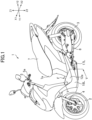
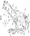
- FIG. 1 is a perspective view of an electric motorcycle 1 as an example of the electric vehicle proposed in the present disclosure.
- Z1 and Z2 shown in FIG. 1 are referred to as upward and downward, respectively.
- Y1 and Y2 shown in FIG. 1 are referred to as frontward and rearward, respectively
- X1 and X2 are referred to as rightward and leftward, respectively.
- the structure proposed in the present disclosure is not only applied to the electric motorcycle, but may be applied to an electric tricycle (including a vehicle having left and right front wheels and one rear wheel placed at the center and a vehicle having one front wheel placed at the center and left and right rear wheels).
- the electric motorcycle 1 has a front wheel 2.
- the front wheel 2 is supported by the lowermost portion of a front fork 4.
- the front fork 4 has a steering shaft in the upper portion thereof.
- the steering shaft is supported by a head pipe 31 (see FIG. 2 ) of a vehicle body frame 30, which will be described later.
- a handle bar 5 is fixed to the upper portion of the steering shaft.
- Grips 5a are provided in the right portion and the left portion of the handle bar 5.
- the electric motorcycle 1 has an electric motor 6 for driving a rear wheel (driving wheel) 3.
- the electric motor 6 may be placed below a seat 7.
- the electric motor 6 may be supported by the vehicle body frame 30. That is, the electric motor 6 may be attached to the vehicle body frame 30 by fastening devices such as bolts.
- the electric motor 6 is attached to left and right frame portions 33L and 33R.
- Output torque of the electric motor 6 is transmitted to the rear wheel 3 via a power transmission mechanism including a chain, a belt, a shaft, etc.
- the electric motorcycle 1 may have a case 8 housing the power transmission mechanism.
- the case 8 is placed at the left side of the rear wheel 3.
- the electric motorcycle 1 may have a rear arm 9 (see FIG. 4 ) placed at the right side of the rear wheel 3.
- the wheel axle of the rear wheel 3 is supported by the case 8 and the rear arm 9.
- the case 8 and the rear arm 9 are movable upward and downward with the rear wheel 3 around a pivot shaft provided at the front end thereof.
- the electric motor 6 is not limited to the example shown in the drawings.
- the electric motor 6 may be provided in the rear wheel 3. That is, the electric motor 6 may be the so-called in-wheel motor.
- the electric motorcycle 1 may have an accommodating case 11 placed under the seat 7.
- the accommodating case 11 opens upward and the seat 7 may function as a lid closing the opening of the accommodating case 11.
- the electric motor 6 may be located below the accommodating case 11.
- the electric motorcycle 1 has an inverter 21 for generating an alternating current for the electric motor 6 from the electric power of a battery 13.
- the inverter 21 is placed between the accommodating case 11 and the electric motor 6.
- the inverter 21 may be placed between the left and right frame portions 33L and 33R and supported by the frame portions 33L and 33R.
- the position of the inverter 21 is not limited to the example shown in the drawings.
- the inverter 21 may be placed at the front side of the electric motor 6 and the rear side of the battery 13.
- the electric motorcycle 1 has a footboard F for a rider to place their feet thereon.
- the footboard F is located further forward than the seat 7 and separated below from the seat 7.
- the footboard F may have a portion located further rearward than a front end 7a of the seat 7.
- An upper surface 12a of the footboard F is lower than the upper end of the front wheel 2 and the upper end of the rear wheel 3.
- the footboard F is located further rearward than the front wheel 2.
- the upper surface 12a of the footboard F may be inclined to be gradually higher toward the rear side.
- the upper surface 12a of the footboard F may be a substantially flat surface continuing from a right edge 12c (see FIG. 5 ) to a left edge 12d (see FIG. 5 ). That is, the footboard F does not necessarily have a center tunnel portion T unlike an electric motorcycle in FIGS. 7A and 7B , which will be described later.
- the vehicle body frame 30 has the head pipe 31 in the forefront portion.
- the head pipe 31 supports the steering shaft (not shown) provided in the upper portion of the front fork 4.
- the vehicle body frame 30 may have a down frame portion 32 extending rearward and downward from the head pipe 31.
- the vehicle body frame 30 has the right frame portion 33R and the left frame portion 33L extending rearward from the lower part of the down frame portion 32.
- the frame portions 33L and 33R are apart in the left-right direction.
- the left and right frame portions 33L and 33R have front portions 33La and 33Ra placed on the footboard F and rear portions 33Lb and 33Rb extending rearward and upward from the front portions 33La and 33Ra.
- the frame portions 33L and 33R are tubular members.
- the tubular members are bent to form the frame portions 33L and 33R.
- the frame portions 33L and 33R have circular sections, however, they may also have rectangular sections or the like, for example. Unlike this, the frame portions 33L and 33R may be forged members or cast members.
- the down frame portion 32 is placed at the center in the left-right direction of the electric motorcycle 1.
- the left and right frame portions 33L and 33R may have forefront portions 33Lc and 33Rc bent from the front portions 33La and 33Ra toward the down frame portion 32 in the forefront parts thereof.
- the vehicle body frame 30 may have left and right reinforcing portions 37 located under the forefront portions 33Lc and 33Rc.
- the left and right reinforcing portions 37 extend from the lower end of the down frame portion 32 and respectively connect to the front portions 33La and 33Ra of the frame portions 33L and 33R.
- a plurality of cross bars 38a and 38b may be attached to the left and right frame portions 33L and 33R.
- the front portions 33La and 33Ra of the frame portions 33L and 33R are referred to as “frame front portions”.
- the rear portions 33Lb and 33Rb of the frame portions 33L and 33R are referred to as "frame rear portions”.
- the accommodating case 11 may be placed between the frame rear portions 33Lb and 33Rb and attached to the frame rear portions 33Lb and 33Rb.
- the seat 7 may be supported by the upper part of the accommodating case 11. Unlike this, the seat 7 may be directly supported by the frame rear portions 33Lb and 33Rb.
- brackets 34 may be attached to the left and right frame portions 33L and 33R.
- the brackets 34 may be located in the forefront parts of the frame rear portions 33Lb and 33Rb.
- the brackets 34 extend obliquely rearward and downward from the frame rear portions 33Lb and 33Rb.
- the brackets 34 support the pivot shaft provided at the front end of the rear arm 9 and the front end of the case 8.
- the electric motorcycle 1 has the battery 13 (see FIG. 4 ) for supplying electric power to the electric motor 6.
- the battery 13 may be e.g., a lithium-ion battery, a nickel-hydrogen battery, or an all-solid-state battery, for example, and the type thereof is not limited.
- the electric motorcycle 1 may have a charging inlet (not shown) to which an external power supply device is connected. Further, the battery 13 may be chargeable by the electric power supplied from an external battery charger. Unlike this, the electric motorcycle 1 does not necessarily have the charging inlet. In this case, the battery 13 may be detached from the vehicle body each time the battery 13 is charged.
- the battery 13 is placed between the left and right frame front portions 33La and 33Ra and at least a part thereof is located in the footboard F. According to the placement of the battery 13, the center of gravity of the vehicle body may be made lower and the weight balance in the front-back direction may be optimized. As shown in FIG. 4 , the front portion of the battery 13 may be located further forward than the front end 7a of the seat 7 and the rear portion of the battery 13 may be located below the seat 7. Unlike this, the entire battery 13 may be located further forward than the front end 7a of the seat 7.
- the battery 13 has a front portion 13A and a rear portion 13B different in height H1 (see FIG. 5 ).
- the height of the rear portion 13B is larger than that of the front portion 13A.
- the height H1 of the battery 13 may be substantially uniform from the front end to the rear end thereof.
- a line Cp shows a vertical plane passing through the center of the vehicle body in the left-right direction.
- the center vertical plane Cp is a plane passing through the center of the front wheel 2 and the rear wheel 3 in the left-right direction and perpendicular to the wheel axles thereof.
- the positions of the left and right frame front portions 33La and 33Ra are asymmetrical about the center vertical plane Cp. That is, a distance L2 from the vertical plane Cp to the left frame front portion 33La, and a distance L1 from the vertical plane Cp to the right frame front portion 33Ra, are different and/or the position of the left frame front portion 33La in the vertical direction (upward or downward direction) and the position of the right frame front portion 33Ra in the same direction are different.
- the positions of the frame front portions 33La and 33Ra refer to e.g., positions of center lines 33n (see FIG. 5 , center lines of the tubular members) thereof.
- the frame front portions 33La and 33Ra may be ranges corresponding to a front end 13a to a rear end 13b of the battery 13.
- the position of the right frame front portion 33Ra is higher than the position of the left frame front portion 33La.
- the position of the right frame front portion 33Ra may be higher than the position of the left frame front portion 33La over an entire range B ( FIGS. 3A and 3B ) of the battery 13 in the front-back direction. That is, a height difference ⁇ H between the left and right frame front portions 33La and 33Ra may be provided in a range from the front end 13a to the rear end 13b of the battery 13 or beyond the range.
- the battery 13 may be easily detached from the electric motorcycle 1 for maintenance or replacement of the battery 13.
- the battery 13 is supported by the frame front portions 33Ra and 33La. As shown in FIG. 5 , for example, the battery 13 may be supported via a stay 14.
- the stay 14 may be provided over the left and right frame front portions 33La and 33Ra.
- the left end and the right end of the stay 14 are respectively fastened to brackets 35 fixed (e.g., welded) to the left and right frame front portions 33La and 33Ra by bolts 15.
- the stay 14 has a supporting portion 14a located in a lower position than the left and right ends thereof and is substantially horizontal.
- the battery 13 is placed on the upper side of the supporting portion 14a.
- a lower surface 13d of the battery 13 may be fixed to the supporting portion 14a by bolts 16.
- a plurality of the stays 14 (e.g., two stays 14) may be placed apart in the front-back direction.
- detaching the battery 13 from the electric motorcycle 1 is performed in the following manner.
- a worker detaches a cover covering the frame front portions 33La and 33Ra from another exterior member.
- the footboard F has covers 17L and 17R covering the lower parts of the frame front portions 33La and 33Ra and covers 18L and 18R covering side parts of the frame front portions 33La and 33Ra as exterior members.
- the covers 17L and 17R are attached to the lower edges of the covers 18L and 18R, respectively.
- the worker detaches the covers 17L and 17R from the covers 18L and 18R.
- the worker places a platform E under the battery 13.
- the upper surface of the platform E may be movable upward and downward.
- the worker detaches the bolts 15 from the brackets 35 of the frame front portions 33La and 33Ra.
- the battery 13 and the stay 14 are detached from the frame front portions 33La and 33Ra and mounted on the platform E.
- the worker moves the platform E to the right side.
- the position of the right frame front portion 33Ra is higher than the left frame front portion 33La, and detaching the battery 13 to the right side of the electric motorcycle 1 may be made easier.
- the electric motorcycle 1 has the charging inlet as described above.
- the battery 13 is not detached in normal use of the electric motorcycle 1, but detached, for example, in case of failure or for maintenance.
- Attaching the battery 13 to the electric motorcycle 1 may be executed in the reverse procedure to that of the detachment work.
- the position of the right frame front portion 33Ra is higher than the left frame front portion 33La, and thereby, the work to attach the battery 13 may be made easier.
- the frame front portions 33Ra and 33La are placed along the side surfaces of the battery 13. That is, the frame front portions 33Ra and 33La may be substantially parallel to the side surfaces of the battery 13.
- the distance L1 from the center vertical plane Cp of the electric motorcycle 1 to the right frame front portion 33Ra is larger than the distance L2 from the same vertical plane Cp to the left frame front portion 33La.
- a gap G2 between the left frame front portion 33La and the left cover 18L is larger than a gap G1 between the right frame front portion 33Ra and the right cover 18R.
- a base portion 19a of a side stand 19 for supporting the electric motorcycle 1 in a tilted state and a bracket 36 to which the base portion 19a is attached may be placed at the left side of the left frame front portion 33La.
- the bracket 36 is fixed to a side part of the frame front portion 33La.
- the side stand 19 is placed along the side surface of the battery 13.
- the base portion 19a and the bracket 36 may be exposed from the cover 17L.
- the component placed at the left side of the left frame front portion 33La is not limited to the side stand 19, but e.g., an electric cable may be placed there.
- the distance L1 from the center vertical plane Cp to the right frame front portion 33Ra is larger than the distance L2 from the same vertical plane Cp to the left frame front portion 33La.
- a center Cb of the battery 13 in the left-right direction shifts rightward from the center vertical plane Cp of the vehicle body. That is, the position of the battery 13 shifts from the center of the vehicle body according to the positions of the left and right frame front portions 33La and 33Ra.
- the distance L1 is larger than the distance L2 over the entire range B of the battery 13. Thereby, the battery 13 can be efficiently placed between the left and right frame front portions 33La and 33Ra.
- the distance between the left and right frame front portions 33La and 33Ra corresponds to the width of the battery 13 in the left-right direction. Thereby, when the stay 14 is detached, the battery 13 may be moved downward without interference between the battery 13 and the frame front portions 33La and 33Ra.
- the position of the right frame front portion 33Ra has the larger distance from the center vertical plane Cp than that of the left frame front portion 33La and is higher than the position the left frame front portion 33La. Accordingly, an angle of bank on the right side (an allowable inclination angle to the right side) of the electric motorcycle 1 is prevented from being reduced. That is, when the right frame front portion 33Ra at the larger distance from the center vertical plane Cp is placed at the same height as that of the left frame front portion 33La, the angle of bank at the right side is restricted by the right frame front portion 33Ra. In the electric motorcycle 1, the reduction of the angle of bank may be avoided by raising the position of the right frame front portion 33Ra.
- the distance L2 from the center vertical plane Cp to the left frame front portion 33La may be larger than the distance L1 from the same vertical plane Cp to the right frame front portion 33Ra.
- the position of the left frame front portion 33La may be higher than the position of the right frame front portion 33Ra.
- the above described difference between the distances L1 and L2 may be provided over the entire range B of the battery 13.
- the difference may be smaller than diameters of the frame front portions 33Ra and 33La.
- the difference between the distances L1 and L2 may be larger than radii of the frame front portions 33Ra and 33La.
- the difference between the distances L1 and L2 is smaller, and thereby, the weight balance in the left-right direction may be secured more easily.
- the difference between the distances L1 and L2 may be uniform or be changed in the entire range B of the battery 13 in the front-back direction.
- the difference ⁇ H between the positions of the right frame front portion 33Ra and the left frame front portion 33La may be smaller than the diameters of the frame front portions 33La and 33Ra. Further, the difference ⁇ H may be larger than the radii of the frame front portions 33La and 33Ra.
- the difference ⁇ H between the positions of the frame front portions 33La and 33Ra may be uniform in the entire range B (see FIG. 3A ) of the battery 13 in the front-back direction or changed depending on the position in the front-back direction.
- the position relationship between the left and right frame front portions 33La and 33Ra is not limited to the example described here.
- the above described difference ⁇ H between the positions may be larger than the diameters of the frame front portions 33Ra and 33La.
- the difference between the distances L1 and L2 may be larger than the diameters of the frame front portions 33Ra and 33La.
- the right frame front portion 33Ra is higher than the left frame front portion 33La in the entire range B of the battery 13. Unlike this, the right frame front portion 33Ra may be higher than the left frame front portion 33La only in a partial range of the battery 13 in the front-back direction. In other words, in a partial range of the battery 13 in the front-back direction, the left and right frame front portions 33La and 33Ra may be located substantially at the same height or the height relationship may be inverted.
- the right frame front portion 33Ra may be higher than the left frame front portion 33La.
- the frame front portions 33La and 33Ra may be located substantially at the same height.
- the position of the right frame front portion 33Ra may be higher than the left frame front portion 33La in a range of the front half part or larger than the front half part of the battery 13, but may be located substantially at the same height in the rearmost part of the battery 13.
- the front half part of the battery 13 refers to a part further forward than a center M of the battery 13 in the front-back direction (see FIG. 3A ).
- the position of the right frame front portion 33Ra may be higher than the left frame front portion 33La in the position at the center M of the battery 13 in the front-back direction.
- the left and right frame front portions 33La and 33Ra may be located substantially at the same height.
- the modification of the heights of the frame front portions 33Ra and 33La may be applied to the distances between the frame front portions 33Ra and 33La and the center vertical plane Cp. That is, unlike the example in FIGS. 2 to 5 , the distance L1 may be larger than the distance L2 only in a major part of the battery 13 in the front-back direction. In other words, the distance L1 may be the same as the distance L2 in a partial range of the battery 13 in the front-back direction.
- the lower surface 13d of the battery 13 may be exposed at the downward facing side of the footboard F.
- the footboard F has an opening between lower edges 17a (see FIG. 5 ) of the left and right covers 17L and 17R.
- the lower surface 13d of the battery 13 is exposed between the lower edges 17a. According to the structure of the footboard F, the battery 13 may be efficiently cooled. Further, detaching the battery 13 may be made easier.
- the battery 13 may have a fin 13c on the lower surface 13d thereof.
- the fin 13c may be exposed downward from the footboard F. Thereby, the battery 13 may be cooled more efficiently.
- the upper part of the battery 13 is covered by an upper panel 12.
- the upper panel 12 also covers the upper part of the right frame front portion 33Ra and the upper part of the left frame front portion 33La. The rider may place their feet on the upper panel 12.
- the positions of the left and right frame front portions 33La and 33Ra are higher than the lower surface 13d of the battery 13. Thereby, the angle of bank of the electric motorcycle 1 may be secured while the center of gravity of the vehicle body of the electric motorcycle 1 is made lower.
- an upper end 33e on the outer circumferential surface of the left frame front portion 33La is lower than an upper surface 13e of the battery 13.
- the position of an upper end 33f on the outer circumferential surface of the right frame front portion 33Ra is at substantially the same height as that of the upper surface 13e of the battery 13 or higher than the upper surface 13e of the battery 13.
- the position of the upper surface 13e of the battery 13 may be higher than both of the upper ends 33e and 33f of the left and right frame front portions 33La and 33Ra.
- the frame front portions 33La and 33Ra are inclined with respect to the horizontal plane and the positions thereof are gradually higher rearward from the front ends thereof. That is, the rear parts of the frame front portions 33La and 33Ra are higher than the positions of the front parts thereof. Further, the upper surface 12a of the footboard F (see FIG. 1 ) is gradually higher rearward from the front end thereof. Thereby, the rider may comfortably place their feet on the footboard F.
- a step is formed in the upper surface 13e of the battery 13, and thus the height H1 of the rear portion 13B of the battery 13 (see FIG. 5 , the distance from the lower surface 13d to the upper surface 13e) is higher than the height of the front portion 13A of the battery 13.
- the capacity of the battery 13 may be increased.
- the position of the front part of the upper surface 12a of the footboard F can be maintained to be lower, and thus the ease of placing the feet of the rider on the footboard F can be maintained.
- the lower surface 13d of the battery 13 may be at the same height in the front portion 13A and the rear portion 13B of the battery 13.
- a plurality of steps may be formed in the upper surface 13e of the battery 13.
- two steps may be formed in the upper surface 13e of the battery 13.
- the height H1 of the center portion of the battery 13 may be larger than the height of the front portion
- the height of the rear portion of the battery 13 may be larger than the height of the center portion.
- FIGS. 6A and 6B show another example of placement of the vehicle body frame and the battery. As shown below, the example shown by these drawings will be explained mainly on differences from the example shown in FIGS. 2 to 5 .
- the structures described in FIGS. 2 to 5 may be applied to structures of the example shown in FIGS. 6A and 6B without an explanation about the structures.
- a vehicle body frame 130 shown in FIG. 6A has left and right frame portions 133L and 133R. Unlike the example shown in FIG. 2 etc., in the vehicle body frame 130, the left and right frame portions 133L and 133R have left and right down frame portions 133Lc and 133Rc, respectively. Upper ends of the down frame portions 133Lc and 133Rc are connected to the head pipe 31.
- the frame portions 133L and 133R have frame front portions 133La and 133Ra placed on the footboard F, respectively.
- the left and right frame front portions 133La and 133Ra extend rearward from the down frame portions 133Lc and 133Rc.
- the battery 13 is placed between the frame front portions 133La and 133Ra.
- the position of the right frame front portion 133Ra is higher than the position of the left frame front portion 133La. Further, a distance L1 from the center vertical plane Cp to the right frame front portion 133Ra is larger than a distance L2 from the center vertical plane Cp to the left frame front portion 133La. Accordingly, the center Cb of the battery 13 in the left-right direction shifts rightward from the center vertical plane Cp of the vehicle body.
- FIGS. 7A and 7B show yet another example of placement of the vehicle body frame and the battery. As shown below, the example shown by these drawings will be explained mainly with respect to the differences from the example shown in FIGS. 2 to 5 .
- the structures described in FIGS. 2 to 5 may be applied to structures of the example shown in FIGS. 7A and 7B without an explanation about the structures.
- a vehicle body frame 230 has a down frame portion 232 extending obliquely downward from a head pipe 131.
- Left and right frame portions 233L and 233R have front inclined portions 233Ld and 233Rd extending downward from the lowermost part of the down frame portion 232 and frame front portions 233La and 233Ra bent and extending rearward from the front inclined portions 233Ld and 233Rd.
- the left and right frame front portions 233La and 233Ra are placed in the footboard F.
- the battery 13 is placed between the left and right frame front portions 233La and 233Ra.
- the position of the right frame front portion 233Ra is higher than the position of the left frame front portion 233La.
- the vehicle body frame 230 has upper frame portions 234L and 234R extending rearward from the down frame portion 232.
- the upper frame portions 234L and 234R have front portions 234La and 234Ra located above the frame front portions 233La and 233Ra.
- the front portions 234La and 234Ra are respectively inclined leftward and rightward so that the distance therebetween may be gradually larger to the rear side.
- Rear portions 234Lb and 234Rb of the upper frame portions 234L and 234R are connected to left and right frame rear portions 233Lb and 233Rb, respectively.
- the footboard F may have left and right side portions F2 and F1.
- the left and right side portions F2 and F1 are formed along the frame front portions 233La and 233Ra.
- the respective side portions F2 and F1 have upper panels 212 for the rider to place their left and right feet (L and R) thereon.
- the upper panels 212 are placed along the upper parts of the frame front portions 233La and 233Ra.
- the upper panels 212 may be supported by the frame front portions 233La and 233Ra.
- the center tunnel portion T may be provided between the left and right side portions F2 and F1.
- the center tunnel portion T has a center cover 219 located between the left and right side portions F2 and F1 and surrounding the above described upper frame portions 234L and 234R.
- the center cover 219 respectively has an upper panel 219a covering the upper parts of the upper frame portions 234L and 234R and side panels 219b and 219c extending downward from the left and right edges of the upper panel 219a.
- the rider places their left and right feet (L and R) on the side portions F2 and F1 with the center tunnel portion T sandwiched by the left and right feet (L and R).
- a part (upper part) of the battery 13 may be located in the center tunnel portion T. In this case, the upper surface of the battery 13 may be higher than both of the left and right frame front portions 233La and 233Ra.
- the footboard F also has an opening that opens downward. That is, the opening is provided between the side portions F2 and F1 and the lower surface 13d of the battery 13 is exposed from the opening.
- a more desirable electric motorcycle in view of detachment of the battery 13 and battery capacity, a more desirable electric motorcycle can be obtained.
- adjusting the heights of the right frame front portions 33Ra, 133Ra and 233Ra makes detachment of the battery 13 toward the right side easier.
- the right frame front portions 33Ra, 133Ra and 233Ra may bend outwards (rightward) in the left-right direction, and thereby, the battery capacity can be increased.
- the right frame front portions 33Ra, 133Ra and 233Ra are higher than the left frame front portions 33La, 133La and 233La in at least a partial portion thereof in the front-back direction. According to the structure, the detachment of the battery 13 toward the right side may be made easier.
- the right frame front portions 33Ra, 133Ra and 233Ra are higher than the left frame front portions 33La, 133La and 233La in the position at the center M of the battery 13 in the front-back direction. According to the structure, the detachment of the battery 13 toward the right side may be made easier.
- the right frame front portions 33Ra, 133Ra and 233Ra are higher than the left frame front portions 33La, 133La and 233La over at least a half length (B/2) of the battery 13 in the front-back direction. According to the structure, the detachment of the battery 13 toward the right side can be made easier.
- the distances L1 of the right frame front portions 33Ra, 133Ra and 233Ra from the vertical plane Cp are larger than the distances L2 of the left frame front portions 33La, 133La and 233La from the vertical plane Cp. According to the configuration, even when the positions of the left frame front portions 33La, 133La and 233La are restricted because a structure or a component is placed at the left side, the battery capacity may be increased.
- the right frame front portions 33Ra, 133Ra and 233Ra are placed at the right side from the vertical plane Cp, and the center Cb of the battery 13 in the left-right direction is located at the right side from the vertical plane Cp.
- the right frame front portions 33Ra, 133Ra and 233Ra are higher than the positions of the left frame front portions 33La, 133La and 233La.
- the stand 19 is attached to the left frame front portions 33La, 133La and 233La.
- the right frame front portions 33Ra, 133Ra and 233Ra are placed at the right side from the vertical plane Cp and the battery 13 is detachable from the footboard F toward the right side.
- the footboard F has an opening that opens downward. Thereby, the detachment of the battery 13 may be made easier.
- Positions of the right frame front portions 33Ra, 133Ra and 233Ra and positions of the left frame front portions 33La, 133La and 233La are higher than the lower surface 13d of the battery 13. According to the configuration, the position of the lower surface 13d of the battery 13 is lowered, and thereby, the battery capacity may be secured and the center of gravity of the vehicle may be made lower. Further, the positions of the left and right frame front portions are higher than the lower surface 13d of the battery 13, and thereby, the angle of bank of the electric motorcycle may be secured.
- the battery 13 is placed between the right frame front portions 33Ra, 133Ra and 233Ra and the left frame front portions 33La, 133La and 233La. According to the configuration, the battery capacity may be secured and the center of gravity of the vehicle may be made lower. Further, the angle of bank of the electric motorcycle may be secured.
- the positions of the rear parts of the right frame front portions 33Ra, 133Ra and 233Ra and the left frame front portions 33La, 133La and 233La are higher than the positions of the front parts thereof. Further, the height H1 of the rear portion 13B of the battery 13 is larger than that of the front portion 13A of the battery 13. According to the configuration, the capacity of the battery 13 may be increased while the ease of placement of a rider's feet on the front portion of the footboard F is maintained.
- the positions of the right frame front portions 33Ra, 133Ra and 233Ra are higher than those of the left frame front portions 33La, 133La and 233La.
- the left frame front portions 33La, 133La and 233La may be higher than the positions of the right frame front portions 33Ra, 133Ra and 233Ra. Detachment of the battery 13 toward the left side may be made easier.
- the distances L2 of the left frame front portions 33La, 133La and 233La from the vertical plane Cp may be larger than the distances L1 of the right frame front portions 33Ra, 133Ra and 233Ra from the vertical plane Cp. According to the configuration, even when the positions of the right frame front portions 33Ra, 133Ra and 233Ra are restricted because a structure or a component is placed at the right side, the battery capacity may be increased.
- the distance L2 from the vertical plane Cp to the left frame front portion 33La and the distance L1 from the vertical plane Cp to the right frame front portion 33Ra are different and, in addition, the position of the left frame front portion 33La in the vertical direction (upward or downward direction) and the position of the right frame front portion 33Ra in the same direction are different.
- the distances L2 and L1 are different, but the position of the left frame front portion 33La in the vertical direction (upward or downward direction) and the position of the right frame front portion 33Ra in the same direction may be substantially the same.
- the distances L2 and L1 are substantially the same, but the position of the left frame front portion 33La in the vertical direction (upward or downward direction) and the position of the right frame front portion 33Ra in the same direction may be different.
- the frame rear portions 33Lb and 33Rb are symmetrical about the center vertical plane Cp.
- these frame rear portions 33Lb and 33Rb may be asymmetrical about the center vertical plane Cp like the frame front portions 33La and 33Ra.
Landscapes
- Engineering & Computer Science (AREA)
- Mechanical Engineering (AREA)
- Chemical & Material Sciences (AREA)
- Combustion & Propulsion (AREA)
- Transportation (AREA)
- Automatic Cycles, And Cycles In General (AREA)
- Arrangement Or Mounting Of Propulsion Units For Vehicles (AREA)
Abstract
Description
- The present disclosure relates to an electric vehicle.
-
JP 2004-358982 A JP 2004-358982 A - In
JP 2004-358982 A -
- (1) An electric vehicle proposed in the present disclosure includes a footboard for a rider to place their feet thereon, a right frame portion and a left frame portion disposed in the footboard and respectively extending in a front-back direction, a rear wheel, an electric motor for driving the rear wheel, and a battery for supplying electric power to the electric motor, the battery being supported by the right frame portion and the left frame portion. Positions of the right frame portion and the left frame portion are asymmetrical about a vertical plane passing through a center of a vehicle body in a left-right direction. The configuration described above can make an electric vehicle more desirable in view of detachment of the battery and the battery capacity. For example, adjusting the height of the frame portion at one side (e.g., the right side) makes detachment of the battery toward the one side easier. In a vehicle where a component is placed only at one side (e.g., the left side) of the vehicle body frame, bending the position of the frame portion at the other side (e.g., the right side) outward (rightward) in the left-right direction can increase the battery capacity.
- (2) In the electric vehicle (1), one of the right frame portion and the left frame portion may be higher than the other frame portion in at least a partial portion thereof in the front-back direction. According to the structure, the detachment of the battery toward the side at which the one frame portion is placed may be made easier.
- (3) In the electric vehicle (1), one of the right frame portion and the left frame portion may be higher than the other frame portion in a center position of the battery in the front-back direction. According to the structure, the detachment of the battery toward the one side may be made easier.
- (4) In the electric vehicle (1), one of the right frame portion and the left frame portion may be higher than the other frame portion over at least a half length of the battery in the front-back direction. According to the structure, the detachment of the battery toward the side at which the one frame portion is placed may be made easier.
- (5) In the electric vehicle (2) to (4), a distance of the one frame portion from the vertical plane may be larger than a distance of the other frame portion from the vertical plane. According to the configuration, even when the position of the other frame portion is restricted because a structure or a component is placed at the side of the other frame portion, the battery capacity may be secured.
- (6) In the electric vehicle (5), the one frame portion may be placed in a first direction from the vertical plane, and a center of the battery in the left-right direction may be located in the first direction from the vertical plane.
- (7) In the electric vehicle (2) to (6), the one frame portion may be the right frame portion, and the other frame portion may be the left frame portion.
- (8) In the electric vehicle (7), a stand may be attached to the left frame portion.
- (9) In the electric vehicle (2) to (4), the one frame portion may be placed in a first direction from the vertical plane, and the battery may be detachable from the footboard in the first direction.
- (10) In the electric vehicle (2) to (4), the footboard may have an opening that opens downward. Thus, the detachment of the battery may be made even easier.
- (11) In the electric vehicle (1) to (10), a position of the right frame portion and a position of the left frame portion may be higher than a lower surface of the battery. According to the configuration, the position of the lower surface of the battery is lowered, and thereby, the battery capacity may be secured and the center of gravity of the vehicle may be lowered. Further, the positions of the left and right frame portions are higher than the lower surface of the battery, and thereby, the angle of bank of the electric vehicle may be easily secured.
- (12) In the electric vehicle (1) to (11), the battery may be placed between the right frame portion and the left frame portion.
- (13) In the electric vehicle (1) to (12), positions of rear parts of the right frame portion and the left frame portion may be higher than positions of front parts thereof. Further, a position of a rear portion of the battery may be higher than a front portion of the battery. According to the configuration, the battery capacity may be increased while it is easier for a rider to place their feet on the front portion of the footboard.
-
-
FIG. 1 is a perspective view showing an electric motorcycle as an example of an electric vehicle proposed in the present disclosure. -
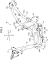
FIG. 2 is a perspective view of a vehicle body frame and a battery of the electric motorcycle inFIG. 1 . -
FIG. 3A is a left side view of the vehicle body frame and the battery of the electric motorcycle inFIG. 1 . -
FIG. 3B is a left side view of the vehicle body frame shown inFIG. 3A . -
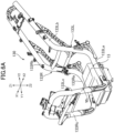
FIG. 4 is a right side view of the vehicle body frame and the battery of the electric motorcycle inFIG. 1 . -
FIG. 5 is a sectional view obtained along line V-V inFIG. 1 . In this drawing, a sign G shows the ground. -
FIG. 6A is a perspective view showing another example of the vehicle body frame. -
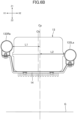
FIG. 6B is a sectional view obtained along line VIb-VIb inFIG. 6A . -
FIG. 7A is a perspective view showing yet another example of the vehicle body frame. -
FIG. 7B is a sectional view of the electric motorcycle obtained along line VIIb-VIIb inFIG. 7A . - As shown below, an electric vehicle proposed in the present disclosure will be explained.
FIG. 1 is a perspective view of an electric motorcycle 1 as an example of the electric vehicle proposed in the present disclosure. Hereinafter, Z1 and Z2 shown inFIG. 1 are referred to as upward and downward, respectively. Further, Y1 and Y2 shown inFIG. 1 are referred to as frontward and rearward, respectively, and X1 and X2 are referred to as rightward and leftward, respectively. Note that the structure proposed in the present disclosure is not only applied to the electric motorcycle, but may be applied to an electric tricycle (including a vehicle having left and right front wheels and one rear wheel placed at the center and a vehicle having one front wheel placed at the center and left and right rear wheels). - As shown in
FIG. 1 , the electric motorcycle 1 has afront wheel 2. Thefront wheel 2 is supported by the lowermost portion of a front fork 4. The front fork 4 has a steering shaft in the upper portion thereof. The steering shaft is supported by a head pipe 31 (seeFIG. 2 ) of avehicle body frame 30, which will be described later. A handle bar 5 is fixed to the upper portion of the steering shaft.Grips 5a are provided in the right portion and the left portion of the handle bar 5. - As shown in
FIG. 4 , the electric motorcycle 1 has anelectric motor 6 for driving a rear wheel (driving wheel) 3. For example, theelectric motor 6 may be placed below aseat 7. Theelectric motor 6 may be supported by thevehicle body frame 30. That is, theelectric motor 6 may be attached to thevehicle body frame 30 by fastening devices such as bolts. In the example shown in the drawings, theelectric motor 6 is attached to left andright frame portions - Output torque of the
electric motor 6 is transmitted to therear wheel 3 via a power transmission mechanism including a chain, a belt, a shaft, etc. As shown inFIG. 1 , the electric motorcycle 1 may have acase 8 housing the power transmission mechanism. Thecase 8 is placed at the left side of therear wheel 3. The electric motorcycle 1 may have a rear arm 9 (seeFIG. 4 ) placed at the right side of therear wheel 3. The wheel axle of therear wheel 3 is supported by thecase 8 and therear arm 9. Thecase 8 and therear arm 9 are movable upward and downward with therear wheel 3 around a pivot shaft provided at the front end thereof. - The placement of the
electric motor 6 is not limited to the example shown in the drawings. For example, theelectric motor 6 may be provided in therear wheel 3. That is, theelectric motor 6 may be the so-called in-wheel motor. - As shown in
FIG. 4 , the electric motorcycle 1 may have anaccommodating case 11 placed under theseat 7. Theaccommodating case 11 opens upward and theseat 7 may function as a lid closing the opening of theaccommodating case 11. Theelectric motor 6 may be located below theaccommodating case 11. - The electric motorcycle 1 has an
inverter 21 for generating an alternating current for theelectric motor 6 from the electric power of abattery 13. As shown inFIG. 3A , for example, theinverter 21 is placed between theaccommodating case 11 and theelectric motor 6. Theinverter 21 may be placed between the left andright frame portions frame portions inverter 21 is not limited to the example shown in the drawings. Theinverter 21 may be placed at the front side of theelectric motor 6 and the rear side of thebattery 13. - As shown in
FIG. 1 , the electric motorcycle 1 has a footboard F for a rider to place their feet thereon. The footboard F is located further forward than theseat 7 and separated below from theseat 7. The footboard F may have a portion located further rearward than afront end 7a of theseat 7. Anupper surface 12a of the footboard F is lower than the upper end of thefront wheel 2 and the upper end of therear wheel 3. The footboard F is located further rearward than thefront wheel 2. Theupper surface 12a of the footboard F may be inclined to be gradually higher toward the rear side. - The
upper surface 12a of the footboard F may be a substantially flat surface continuing from aright edge 12c (seeFIG. 5 ) to aleft edge 12d (seeFIG. 5 ). That is, the footboard F does not necessarily have a center tunnel portion T unlike an electric motorcycle inFIGS. 7A and7B , which will be described later. - As shown in
FIG. 2 , thevehicle body frame 30 has thehead pipe 31 in the forefront portion. Thehead pipe 31 supports the steering shaft (not shown) provided in the upper portion of the front fork 4. Thevehicle body frame 30 may have adown frame portion 32 extending rearward and downward from thehead pipe 31. - As shown in
FIG. 2 , thevehicle body frame 30 has theright frame portion 33R and theleft frame portion 33L extending rearward from the lower part of thedown frame portion 32. Theframe portions right frame portions frame portions frame portions frame portions frame portions - As shown in
FIG. 2 , thedown frame portion 32 is placed at the center in the left-right direction of the electric motorcycle 1. The left andright frame portions down frame portion 32 in the forefront parts thereof. Thevehicle body frame 30 may have left and right reinforcingportions 37 located under the forefront portions 33Lc and 33Rc. The left and right reinforcingportions 37 extend from the lower end of thedown frame portion 32 and respectively connect to the front portions 33La and 33Ra of theframe portions cross bars right frame portions - Hereinafter, the front portions 33La and 33Ra of the
frame portions frame portions - The
accommodating case 11 may be placed between the frame rear portions 33Lb and 33Rb and attached to the frame rear portions 33Lb and 33Rb. Theseat 7 may be supported by the upper part of theaccommodating case 11. Unlike this, theseat 7 may be directly supported by the frame rear portions 33Lb and 33Rb. - As shown in
FIGS. 3A and4 ,brackets 34 may be attached to the left andright frame portions brackets 34 may be located in the forefront parts of the frame rear portions 33Lb and 33Rb. Thebrackets 34 extend obliquely rearward and downward from the frame rear portions 33Lb and 33Rb. Thebrackets 34 support the pivot shaft provided at the front end of therear arm 9 and the front end of thecase 8. - The electric motorcycle 1 has the battery 13 (see
FIG. 4 ) for supplying electric power to theelectric motor 6. Thebattery 13 may be e.g., a lithium-ion battery, a nickel-hydrogen battery, or an all-solid-state battery, for example, and the type thereof is not limited. The electric motorcycle 1 may have a charging inlet (not shown) to which an external power supply device is connected. Further, thebattery 13 may be chargeable by the electric power supplied from an external battery charger. Unlike this, the electric motorcycle 1 does not necessarily have the charging inlet. In this case, thebattery 13 may be detached from the vehicle body each time thebattery 13 is charged. - As shown in
FIGS. 3A and4 , thebattery 13 is placed between the left and right frame front portions 33La and 33Ra and at least a part thereof is located in the footboard F. According to the placement of thebattery 13, the center of gravity of the vehicle body may be made lower and the weight balance in the front-back direction may be optimized. As shown inFIG. 4 , the front portion of thebattery 13 may be located further forward than thefront end 7a of theseat 7 and the rear portion of thebattery 13 may be located below theseat 7. Unlike this, theentire battery 13 may be located further forward than thefront end 7a of theseat 7. - In the example shown in
FIG. 2 , thebattery 13 has afront portion 13A and arear portion 13B different in height H1 (seeFIG. 5 ). The height of therear portion 13B is larger than that of thefront portion 13A. Unlike the example shown inFIG. 2 , the height H1 of thebattery 13 may be substantially uniform from the front end to the rear end thereof. - In
FIG. 5 , a line Cp shows a vertical plane passing through the center of the vehicle body in the left-right direction. The center vertical plane Cp is a plane passing through the center of thefront wheel 2 and therear wheel 3 in the left-right direction and perpendicular to the wheel axles thereof. The positions of the left and right frame front portions 33La and 33Ra are asymmetrical about the center vertical plane Cp. That is, a distance L2 from the vertical plane Cp to the left frame front portion 33La, and a distance L1 from the vertical plane Cp to the right frame front portion 33Ra, are different and/or the position of the left frame front portion 33La in the vertical direction (upward or downward direction) and the position of the right frame front portion 33Ra in the same direction are different. - In the description, "the positions of the frame front portions 33La and 33Ra" refer to e.g., positions of
center lines 33n (seeFIG. 5 , center lines of the tubular members) thereof. In this specification, the frame front portions 33La and 33Ra may be ranges corresponding to afront end 13a to arear end 13b of thebattery 13. - As shown in
FIG. 5 , the position of the right frame front portion 33Ra is higher than the position of the left frame front portion 33La. In detail, the position of the right frame front portion 33Ra may be higher than the position of the left frame front portion 33La over an entire range B (FIGS. 3A and3B ) of thebattery 13 in the front-back direction. That is, a height difference ΔH between the left and right frame front portions 33La and 33Ra may be provided in a range from thefront end 13a to therear end 13b of thebattery 13 or beyond the range. According to the placement of the frame front portions 33La and 33Ra, thebattery 13 may be easily detached from the electric motorcycle 1 for maintenance or replacement of thebattery 13. - The
battery 13 is supported by the frame front portions 33Ra and 33La. As shown inFIG. 5 , for example, thebattery 13 may be supported via astay 14. Thestay 14 may be provided over the left and right frame front portions 33La and 33Ra. In the example shown in the drawings, the left end and the right end of thestay 14 are respectively fastened tobrackets 35 fixed (e.g., welded) to the left and right frame front portions 33La and 33Ra bybolts 15. Thestay 14 has a supportingportion 14a located in a lower position than the left and right ends thereof and is substantially horizontal. Thebattery 13 is placed on the upper side of the supportingportion 14a. Alower surface 13d of thebattery 13 may be fixed to the supportingportion 14a bybolts 16. A plurality of the stays 14 (e.g., two stays 14) may be placed apart in the front-back direction. - For example, detaching the
battery 13 from the electric motorcycle 1 is performed in the following manner. First, a worker detaches a cover covering the frame front portions 33La and 33Ra from another exterior member. In the example shown in the drawings, the footboard F hascovers covers covers covers covers battery 13. The upper surface of the platform E may be movable upward and downward. Then, the worker detaches thebolts 15 from thebrackets 35 of the frame front portions 33La and 33Ra. Thereby, thebattery 13 and thestay 14 are detached from the frame front portions 33La and 33Ra and mounted on the platform E. The worker moves the platform E to the right side. In the electric motorcycle 1, the position of the right frame front portion 33Ra is higher than the left frame front portion 33La, and detaching thebattery 13 to the right side of the electric motorcycle 1 may be made easier. Note that the electric motorcycle 1 has the charging inlet as described above. Thebattery 13 is not detached in normal use of the electric motorcycle 1, but detached, for example, in case of failure or for maintenance. - Attaching the
battery 13 to the electric motorcycle 1 may be executed in the reverse procedure to that of the detachment work. The position of the right frame front portion 33Ra is higher than the left frame front portion 33La, and thereby, the work to attach thebattery 13 may be made easier. - The frame front portions 33Ra and 33La are placed along the side surfaces of the
battery 13. That is, the frame front portions 33Ra and 33La may be substantially parallel to the side surfaces of thebattery 13. As shown inFIG. 5 , the distance L1 from the center vertical plane Cp of the electric motorcycle 1 to the right frame front portion 33Ra is larger than the distance L2 from the same vertical plane Cp to the left frame front portion 33La. Accordingly, a gap G2 between the left frame front portion 33La and theleft cover 18L is larger than a gap G1 between the right frame front portion 33Ra and theright cover 18R. Thereby, reduction of an angle of bank at the left side (an allowable inclination angle to the left side) of the electric motorcycle 1 may be suppressed, and various structures and components may be placed at the left side of the left frame front portion 33La. - For example, as shown in
FIGS. 3A and3B , abase portion 19a of aside stand 19 for supporting the electric motorcycle 1 in a tilted state and abracket 36 to which thebase portion 19a is attached may be placed at the left side of the left frame front portion 33La. Thebracket 36 is fixed to a side part of the frame front portion 33La. The side stand 19 is placed along the side surface of thebattery 13. Thebase portion 19a and thebracket 36 may be exposed from thecover 17L. The component placed at the left side of the left frame front portion 33La is not limited to theside stand 19, but e.g., an electric cable may be placed there. - As described above, the distance L1 from the center vertical plane Cp to the right frame front portion 33Ra is larger than the distance L2 from the same vertical plane Cp to the left frame front portion 33La. As shown in
FIG. 5 , a center Cb of thebattery 13 in the left-right direction shifts rightward from the center vertical plane Cp of the vehicle body. That is, the position of thebattery 13 shifts from the center of the vehicle body according to the positions of the left and right frame front portions 33La and 33Ra. In the electric motorcycle 1, the distance L1 is larger than the distance L2 over the entire range B of thebattery 13. Thereby, thebattery 13 can be efficiently placed between the left and right frame front portions 33La and 33Ra. The distance between the left and right frame front portions 33La and 33Ra corresponds to the width of thebattery 13 in the left-right direction. Thereby, when thestay 14 is detached, thebattery 13 may be moved downward without interference between thebattery 13 and the frame front portions 33La and 33Ra. - As shown in
FIG. 5 , the position of the right frame front portion 33Ra has the larger distance from the center vertical plane Cp than that of the left frame front portion 33La and is higher than the position the left frame front portion 33La. Accordingly, an angle of bank on the right side (an allowable inclination angle to the right side) of the electric motorcycle 1 is prevented from being reduced. That is, when the right frame front portion 33Ra at the larger distance from the center vertical plane Cp is placed at the same height as that of the left frame front portion 33La, the angle of bank at the right side is restricted by the right frame front portion 33Ra. In the electric motorcycle 1, the reduction of the angle of bank may be avoided by raising the position of the right frame front portion 33Ra. - Note that, in contrast to the example shown in the drawings, the distance L2 from the center vertical plane Cp to the left frame front portion 33La may be larger than the distance L1 from the same vertical plane Cp to the right frame front portion 33Ra. In this case, the position of the left frame front portion 33La may be higher than the position of the right frame front portion 33Ra.
- The above described difference between the distances L1 and L2 (see
FIG. 5 ) may be provided over the entire range B of thebattery 13. The difference may be smaller than diameters of the frame front portions 33Ra and 33La. Further, the difference between the distances L1 and L2 may be larger than radii of the frame front portions 33Ra and 33La. As described above, the difference between the distances L1 and L2 is smaller, and thereby, the weight balance in the left-right direction may be secured more easily. Note that the difference between the distances L1 and L2 may be uniform or be changed in the entire range B of thebattery 13 in the front-back direction. - Further, as shown in
FIG. 5 , for example, the difference ΔH between the positions of the right frame front portion 33Ra and the left frame front portion 33La may be smaller than the diameters of the frame front portions 33La and 33Ra. Further, the difference ΔH may be larger than the radii of the frame front portions 33La and 33Ra. The difference ΔH between the positions of the frame front portions 33La and 33Ra may be uniform in the entire range B (seeFIG. 3A ) of thebattery 13 in the front-back direction or changed depending on the position in the front-back direction. - Note that the position relationship between the left and right frame front portions 33La and 33Ra is not limited to the example described here. For example, the above described difference ΔH between the positions may be larger than the diameters of the frame front portions 33Ra and 33La. Further, the difference between the distances L1 and L2 may be larger than the diameters of the frame front portions 33Ra and 33La.
- In the example shown in
FIGS. 2 to 5 , the right frame front portion 33Ra is higher than the left frame front portion 33La in the entire range B of thebattery 13. Unlike this, the right frame front portion 33Ra may be higher than the left frame front portion 33La only in a partial range of thebattery 13 in the front-back direction. In other words, in a partial range of thebattery 13 in the front-back direction, the left and right frame front portions 33La and 33Ra may be located substantially at the same height or the height relationship may be inverted. - For example, in a range of a half of the
battery 13 in the front-back direction (B/2) or in a range larger than the half, the right frame front portion 33Ra may be higher than the left frame front portion 33La. In the other ranges, the frame front portions 33La and 33Ra may be located substantially at the same height. For example, the position of the right frame front portion 33Ra may be higher than the left frame front portion 33La in a range of the front half part or larger than the front half part of thebattery 13, but may be located substantially at the same height in the rearmost part of thebattery 13. Here, the front half part of thebattery 13 refers to a part further forward than a center M of thebattery 13 in the front-back direction (seeFIG. 3A ). - As another example, the position of the right frame front portion 33Ra may be higher than the left frame front portion 33La in the position at the center M of the
battery 13 in the front-back direction. On the other hand, in the position of thefront end 13a and/or the position of therear end 13b of thebattery 13, the left and right frame front portions 33La and 33Ra may be located substantially at the same height. - The modification of the heights of the frame front portions 33Ra and 33La may be applied to the distances between the frame front portions 33Ra and 33La and the center vertical plane Cp. That is, unlike the example in
FIGS. 2 to 5 , the distance L1 may be larger than the distance L2 only in a major part of thebattery 13 in the front-back direction. In other words, the distance L1 may be the same as the distance L2 in a partial range of thebattery 13 in the front-back direction. - As shown in
FIG. 5 , thelower surface 13d of thebattery 13 may be exposed at the downward facing side of the footboard F. In the example shown in the drawings, the footboard F has an opening betweenlower edges 17a (seeFIG. 5 ) of the left andright covers lower surface 13d of thebattery 13 is exposed between thelower edges 17a. According to the structure of the footboard F, thebattery 13 may be efficiently cooled. Further, detaching thebattery 13 may be made easier. - As shown in
FIG. 5 , thebattery 13 may have afin 13c on thelower surface 13d thereof. Thefin 13c may be exposed downward from the footboard F. Thereby, thebattery 13 may be cooled more efficiently. - As shown in
FIG. 5 , the upper part of thebattery 13 is covered by anupper panel 12. Theupper panel 12 also covers the upper part of the right frame front portion 33Ra and the upper part of the left frame front portion 33La. The rider may place their feet on theupper panel 12. - As shown in
FIG. 5 , the positions of the left and right frame front portions 33La and 33Ra are higher than thelower surface 13d of thebattery 13. Thereby, the angle of bank of the electric motorcycle 1 may be secured while the center of gravity of the vehicle body of the electric motorcycle 1 is made lower. - As shown in
FIG. 5 , anupper end 33e on the outer circumferential surface of the left frame front portion 33La is lower than anupper surface 13e of thebattery 13. On the other hand, the position of anupper end 33f on the outer circumferential surface of the right frame front portion 33Ra is at substantially the same height as that of theupper surface 13e of thebattery 13 or higher than theupper surface 13e of thebattery 13. Unlike this, the position of theupper surface 13e of thebattery 13 may be higher than both of the upper ends 33e and 33f of the left and right frame front portions 33La and 33Ra. - As shown in
FIG. 2 , the frame front portions 33La and 33Ra are inclined with respect to the horizontal plane and the positions thereof are gradually higher rearward from the front ends thereof. That is, the rear parts of the frame front portions 33La and 33Ra are higher than the positions of the front parts thereof. Further, theupper surface 12a of the footboard F (seeFIG. 1 ) is gradually higher rearward from the front end thereof. Thereby, the rider may comfortably place their feet on the footboard F. - As shown in
FIG. 2 , a step is formed in theupper surface 13e of thebattery 13, and thus the height H1 of therear portion 13B of the battery 13 (seeFIG. 5 , the distance from thelower surface 13d to theupper surface 13e) is higher than the height of thefront portion 13A of thebattery 13. According to the structure, the capacity of thebattery 13 may be increased. Further, according to the structure, the position of the front part of theupper surface 12a of the footboard F can be maintained to be lower, and thus the ease of placing the feet of the rider on the footboard F can be maintained. Note that, unlike theupper surface 13e, thelower surface 13d of thebattery 13 may be at the same height in thefront portion 13A and therear portion 13B of thebattery 13. - A plurality of steps may be formed in the
upper surface 13e of thebattery 13. For example, two steps may be formed in theupper surface 13e of thebattery 13. In this case, the height H1 of the center portion of thebattery 13 may be larger than the height of the front portion, and the height of the rear portion of thebattery 13 may be larger than the height of the center portion. - The electric motorcycle proposed in the present disclosure is not limited to the example shown in
FIGS. 2 to 5 .FIGS. 6A and6B show another example of placement of the vehicle body frame and the battery. As shown below, the example shown by these drawings will be explained mainly on differences from the example shown inFIGS. 2 to 5 . The structures described inFIGS. 2 to 5 may be applied to structures of the example shown inFIGS. 6A and6B without an explanation about the structures. - A
vehicle body frame 130 shown inFIG. 6A has left andright frame portions FIG. 2 etc., in thevehicle body frame 130, the left andright frame portions head pipe 31. - Like the example shown in
FIG. 2 etc., theframe portions FIG. 6B , thebattery 13 is placed between the frame front portions 133La and 133Ra. - As shown in
FIG. 6B , the position of the right frame front portion 133Ra is higher than the position of the left frame front portion 133La. Further, a distance L1 from the center vertical plane Cp to the right frame front portion 133Ra is larger than a distance L2 from the center vertical plane Cp to the left frame front portion 133La. Accordingly, the center Cb of thebattery 13 in the left-right direction shifts rightward from the center vertical plane Cp of the vehicle body. -
FIGS. 7A and7B show yet another example of placement of the vehicle body frame and the battery. As shown below, the example shown by these drawings will be explained mainly with respect to the differences from the example shown inFIGS. 2 to 5 . The structures described inFIGS. 2 to 5 may be applied to structures of the example shown inFIGS. 7A and7B without an explanation about the structures. - As shown in
FIG. 7A , avehicle body frame 230 has adown frame portion 232 extending obliquely downward from a head pipe 131. Left andright frame portions down frame portion 232 and frame front portions 233La and 233Ra bent and extending rearward from the front inclined portions 233Ld and 233Rd. Like the example shown inFIG. 2 etc., the left and right frame front portions 233La and 233Ra are placed in the footboard F. Thebattery 13 is placed between the left and right frame front portions 233La and 233Ra. As shown inFIG. 7B , the position of the right frame front portion 233Ra is higher than the position of the left frame front portion 233La. - As shown in
FIG. 7A , thevehicle body frame 230 hasupper frame portions down frame portion 232. Theupper frame portions upper frame portions - As shown in
FIG. 7B , in the electric motorcycle having thevehicle body frame 230, the footboard F may have left and right side portions F2 and F1. The left and right side portions F2 and F1 are formed along the frame front portions 233La and 233Ra. The respective side portions F2 and F1 haveupper panels 212 for the rider to place their left and right feet (L and R) thereon. Theupper panels 212 are placed along the upper parts of the frame front portions 233La and 233Ra. Theupper panels 212 may be supported by the frame front portions 233La and 233Ra. - As shown in
FIG. 7B , in the electric motorcycle having thevehicle body frame 230, the center tunnel portion T may be provided between the left and right side portions F2 and F1. The center tunnel portion T has acenter cover 219 located between the left and right side portions F2 and F1 and surrounding the above describedupper frame portions center cover 219 respectively has anupper panel 219a covering the upper parts of theupper frame portions side panels upper panel 219a. The rider places their left and right feet (L and R) on the side portions F2 and F1 with the center tunnel portion T sandwiched by the left and right feet (L and R). A part (upper part) of thebattery 13 may be located in the center tunnel portion T. In this case, the upper surface of thebattery 13 may be higher than both of the left and right frame front portions 233La and 233Ra. - As shown in
FIG. 7B , in the electric motorcycle having thevehicle body frame 230, the footboard F also has an opening that opens downward. That is, the opening is provided between the side portions F2 and F1 and thelower surface 13d of thebattery 13 is exposed from the opening. -
- (1) The electric motorcycle proposed in the present disclosure includes the footboard F for the rider to place their feet thereon, the right frame portion (more specifically, the frame front portions 33Ra, 133Ra and 233Ra) and the left frame portion (more specifically, the frame front portions 33La, 133La and 233La) disposed in the footboard F and respectively extending in a front-back direction, the
rear wheel 3, theelectric motor 6 for driving therear wheel 3, and thebattery 13 supported by the right frame front portions 33Ra, 133Ra and 233Ra and the left frame front portions 33La, 133La and 233La. Positions of the right frame front portions 33Ra, 133Ra and 233Ra and positions of the left frame front portions 33La, 133La and 233La are asymmetrical about the vertical plane Cp passing through the center of the vehicle body in the left-right direction. - According to the configuration, in view of detachment of the
battery 13 and battery capacity, a more desirable electric motorcycle can be obtained. For example, adjusting the heights of the right frame front portions 33Ra, 133Ra and 233Ra makes detachment of thebattery 13 toward the right side easier. Further, when a component is placed at the left side of the vehicle body frames 30, 130 and 230, the right frame front portions 33Ra, 133Ra and 233Ra may bend outwards (rightward) in the left-right direction, and thereby, the battery capacity can be increased. - (2) The right frame front portions 33Ra, 133Ra and 233Ra are higher than the left frame front portions 33La, 133La and 233La in at least a partial portion thereof in the front-back direction. According to the structure, the detachment of the
battery 13 toward the right side may be made easier. - (3) The right frame front portions 33Ra, 133Ra and 233Ra are higher than the left frame front portions 33La, 133La and 233La in the position at the center M of the
battery 13 in the front-back direction. According to the structure, the detachment of thebattery 13 toward the right side may be made easier. - (4) The right frame front portions 33Ra, 133Ra and 233Ra are higher than the left frame front portions 33La, 133La and 233La over at least a half length (B/2) of the
battery 13 in the front-back direction. According to the structure, the detachment of thebattery 13 toward the right side can be made easier. - (5) The distances L1 of the right frame front portions 33Ra, 133Ra and 233Ra from the vertical plane Cp are larger than the distances L2 of the left frame front portions 33La, 133La and 233La from the vertical plane Cp. According to the configuration, even when the positions of the left frame front portions 33La, 133La and 233La are restricted because a structure or a component is placed at the left side, the battery capacity may be increased.
- (6) The right frame front portions 33Ra, 133Ra and 233Ra are placed at the right side from the vertical plane Cp, and the center Cb of the
battery 13 in the left-right direction is located at the right side from the vertical plane Cp. - (7) Of the left and right frame front portions, the right frame front portions 33Ra, 133Ra and 233Ra are higher than the positions of the left frame front portions 33La, 133La and 233La.
- (8) Further, the
stand 19 is attached to the left frame front portions 33La, 133La and 233La. - (9) The right frame front portions 33Ra, 133Ra and 233Ra are placed at the right side from the vertical plane Cp and the
battery 13 is detachable from the footboard F toward the right side. - (10) The footboard F has an opening that opens downward. Thereby, the detachment of the
battery 13 may be made easier. - (11) Positions of the right frame front portions 33Ra, 133Ra and 233Ra and positions of the left frame front portions 33La, 133La and 233La are higher than the
lower surface 13d of thebattery 13. According to the configuration, the position of thelower surface 13d of thebattery 13 is lowered, and thereby, the battery capacity may be secured and the center of gravity of the vehicle may be made lower. Further, the positions of the left and right frame front portions are higher than thelower surface 13d of thebattery 13, and thereby, the angle of bank of the electric motorcycle may be secured. - (12) The
battery 13 is placed between the right frame front portions 33Ra, 133Ra and 233Ra and the left frame front portions 33La, 133La and 233La. According to the configuration, the battery capacity may be secured and the center of gravity of the vehicle may be made lower. Further, the angle of bank of the electric motorcycle may be secured. - (13) The positions of the rear parts of the right frame front portions 33Ra, 133Ra and 233Ra and the left frame front portions 33La, 133La and 233La are higher than the positions of the front parts thereof. Further, the height H1 of the
rear portion 13B of thebattery 13 is larger than that of thefront portion 13A of thebattery 13. According to the configuration, the capacity of thebattery 13 may be increased while the ease of placement of a rider's feet on the front portion of the footboard F is maintained. - Note that the electric vehicle proposed in the present disclosure is not limited to the above described electric motorcycle.
- For example, in the above described electric motorcycle, the positions of the right frame front portions 33Ra, 133Ra and 233Ra are higher than those of the left frame front portions 33La, 133La and 233La. In contrast, the left frame front portions 33La, 133La and 233La may be higher than the positions of the right frame front portions 33Ra, 133Ra and 233Ra. Detachment of the
battery 13 toward the left side may be made easier. Further, in this case, the distances L2 of the left frame front portions 33La, 133La and 233La from the vertical plane Cp may be larger than the distances L1 of the right frame front portions 33Ra, 133Ra and 233Ra from the vertical plane Cp. According to the configuration, even when the positions of the right frame front portions 33Ra, 133Ra and 233Ra are restricted because a structure or a component is placed at the right side, the battery capacity may be increased. - In the above described electric motorcycle, the distance L2 from the vertical plane Cp to the left frame front portion 33La and the distance L1 from the vertical plane Cp to the right frame front portion 33Ra are different and, in addition, the position of the left frame front portion 33La in the vertical direction (upward or downward direction) and the position of the right frame front portion 33Ra in the same direction are different. Unlike this, the distances L2 and L1 are different, but the position of the left frame front portion 33La in the vertical direction (upward or downward direction) and the position of the right frame front portion 33Ra in the same direction may be substantially the same. In contrast, the distances L2 and L1 are substantially the same, but the position of the left frame front portion 33La in the vertical direction (upward or downward direction) and the position of the right frame front portion 33Ra in the same direction may be different.
- In the example shown in
FIGS. 2 to 5 , the frame rear portions 33Lb and 33Rb are symmetrical about the center vertical plane Cp. However, these frame rear portions 33Lb and 33Rb may be asymmetrical about the center vertical plane Cp like the frame front portions 33La and 33Ra.
Claims (13)
- An electric vehicle comprising:a footboard for an rider to place feet thereon;a right frame portion and a left frame portion disposed in the footboard and respectively extending in a front-back direction;a rear wheel;an electric motor for driving the rear wheel; anda battery for supplying electric power to the electric motor, the battery being supported by the right frame portion and the left frame portion, whereinpositions of the right frame portion and the left frame portion are asymmetrical about a vertical plane passing through a center of a vehicle body in a left-right direction.
- The electric vehicle according to claim 1, wherein
one of the right frame portion and the left frame portion is higher than the other frame portion in at least a partial portion thereof in the front-back direction. - The electric vehicle according to claim 1, wherein
one of the right frame portion and the left frame portion is higher than the other frame portion in a center position of the battery in the front-back direction. - The electric vehicle according to claim 1, wherein
one of the right frame portion and the left frame portion is higher than the other frame portion over at least a half length of the battery in the front-back direction. - The electric vehicle according to any one of claims 2 to 4, wherein
a distance of the one frame portion from the vertical plane is larger than a distance of the other frame portion from the vertical plane. - The electric vehicle according to claim 5, whereinthe one frame portion is placed in a first direction from the vertical plane, anda center of the battery in the left-right direction is located in the first direction from the vertical plane.
- The electric vehicle according to any one of claims 2 to 6, whereinthe one frame portion is the right frame portion, andthe other frame portion is the left frame portion.
- The electric vehicle according to claim 7, wherein
a stand is attached to the left frame portion. - The electric vehicle according to any one of claims 2 to 4, whereinthe one frame portion is placed in a first direction from the vertical plane, andthe battery is detachable from the footboard in the first direction.
- The electric vehicle according to any one of claims 2 to 4, wherein
the footboard has an opening that opens downward. - The electric vehicle according to any one of claims 1 to 10, wherein
a position of the right frame portion and a position of the left frame portion are higher than a lower surface of the battery. - The electric vehicle according to any one of claims 1 to 11, wherein
the battery is placed between the right frame portion and the left frame portion. - The electric vehicle according to any one of claims 1 to 12, whereinpositions of rear parts of the right frame portion and the left frame portion are higher than positions of front parts thereof, anda height of a rear portion of the battery is larger than that of a front portion of the battery.
Applications Claiming Priority (2)
| Application Number | Priority Date | Filing Date | Title |
|---|---|---|---|
| JP2021203708A JP2022027936A (en) | 2021-12-15 | 2021-12-15 | Electric vehicle |
| PCT/JP2022/019161 WO2023112351A1 (en) | 2021-12-15 | 2022-04-27 | Electric vehicle |
Publications (2)
| Publication Number | Publication Date |
|---|---|
| EP4450374A1 true EP4450374A1 (en) | 2024-10-23 |
| EP4450374A4 EP4450374A4 (en) | 2025-11-12 |
Family
ID=80265073
Family Applications (1)
| Application Number | Title | Priority Date | Filing Date |
|---|---|---|---|
| EP22906888.7A Pending EP4450374A4 (en) | 2021-12-15 | 2022-04-27 | ELECTRIC VEHICLE |
Country Status (5)
| Country | Link |
|---|---|
| US (1) | US20250042494A1 (en) |
| EP (1) | EP4450374A4 (en) |
| JP (1) | JP2022027936A (en) |
| CN (1) | CN118510696A (en) |
| WO (1) | WO2023112351A1 (en) |
Families Citing this family (1)
| Publication number | Priority date | Publication date | Assignee | Title |
|---|---|---|---|---|
| JP2022027936A (en) * | 2021-12-15 | 2022-02-14 | ヤマハ発動機株式会社 | Electric vehicle |
Family Cites Families (12)
| Publication number | Priority date | Publication date | Assignee | Title |
|---|---|---|---|---|
| JP4233714B2 (en) * | 1999-10-19 | 2009-03-04 | ヤマハ発動機株式会社 | Battery cooling structure for electric vehicles |
| JP2003019994A (en) * | 2001-07-09 | 2003-01-21 | Yamaha Motor Co Ltd | Body frame of scooter type motorcycle |
| JP4176339B2 (en) * | 2001-10-19 | 2008-11-05 | ヤマハ発動機株式会社 | Electric motorcycle frame structure |
| JP2004358982A (en) | 2003-05-30 | 2004-12-24 | Honda Motor Co Ltd | Electric vehicle |
| JP2005280656A (en) * | 2004-03-31 | 2005-10-13 | Honda Motor Co Ltd | Electric vehicle |
| TW201012695A (en) * | 2008-09-30 | 2010-04-01 | Honda Motor Co Ltd | Saddle-ride electric vehicle |
| JP5225913B2 (en) * | 2009-03-27 | 2013-07-03 | 本田技研工業株式会社 | Electric vehicle |
| WO2012070109A1 (en) * | 2010-11-22 | 2012-05-31 | ヤマハ発動機株式会社 | Two-wheeled electric vehicle |
| JP2015113074A (en) * | 2013-12-13 | 2015-06-22 | ヤマハ発動機株式会社 | Saddle-riding type vehicle |
| WO2017038820A1 (en) * | 2015-08-31 | 2017-03-09 | 本田技研工業株式会社 | Saddled electric vehicle |
| CN113365907B (en) * | 2019-02-13 | 2023-03-28 | 本田技研工业株式会社 | Saddle-ride type electric vehicle |
| JP2022027936A (en) * | 2021-12-15 | 2022-02-14 | ヤマハ発動機株式会社 | Electric vehicle |
-
2021
- 2021-12-15 JP JP2021203708A patent/JP2022027936A/en active Pending
-
2022
- 2022-04-27 EP EP22906888.7A patent/EP4450374A4/en active Pending
- 2022-04-27 CN CN202280083014.7A patent/CN118510696A/en active Pending
- 2022-04-27 US US18/718,063 patent/US20250042494A1/en active Pending
- 2022-04-27 WO PCT/JP2022/019161 patent/WO2023112351A1/en not_active Ceased
Also Published As
| Publication number | Publication date |
|---|---|
| WO2023112351A1 (en) | 2023-06-22 |
| CN118510696A (en) | 2024-08-16 |
| US20250042494A1 (en) | 2025-02-06 |
| JP2022027936A (en) | 2022-02-14 |
| EP4450374A4 (en) | 2025-11-12 |
Similar Documents
| Publication | Publication Date | Title |
|---|---|---|
| US8789640B2 (en) | Electric motorcycle | |
| JP6183089B2 (en) | Electric vehicle | |
| JP5052922B2 (en) | Motorcycle | |
| CN103209886B (en) | The actuating device of elec. vehicle | |
| JP5595228B2 (en) | Electric vehicle | |
| US9132878B2 (en) | Electric motorcycle | |
| US20240383345A1 (en) | Electric All-Terrain Vehicle | |
| US20140339008A1 (en) | Straddle Electric Vehicle | |
| JPWO2019194048A1 (en) | Electric vehicle | |
| JP7118182B2 (en) | saddle type electric vehicle | |
| JP7477686B2 (en) | Electric truck frame | |
| EP4450374A1 (en) | Electric vehicle | |
| JPWO2020188706A1 (en) | Saddle-type electric vehicle | |
| JP5492742B2 (en) | Cooling duct routing structure for saddle-ride type electric vehicles | |
| JP7097979B2 (en) | Saddle-type vehicle | |
| JP7676514B1 (en) | Saddle-type electric vehicle | |
| JP7367496B2 (en) | saddle type vehicle | |
| JP7796789B2 (en) | Saddle-type electric vehicle | |
| JP7734778B1 (en) | Vehicle structure of saddle-type electric vehicle | |
| JP7826689B2 (en) | electric tricycle | |
| US20260015059A1 (en) | Straddled electric vehicle | |
| JP7847657B2 (en) | Saddle-type vehicle | |
| JP7676614B1 (en) | Terminal protection structure for saddle-type vehicles | |
| JP2025141529A (en) | Vehicle structure | |
| WO2026069696A1 (en) | Electric saddle-ridden vehicle |
Legal Events
| Date | Code | Title | Description |
|---|---|---|---|
| STAA | Information on the status of an ep patent application or granted ep patent |
Free format text: STATUS: THE INTERNATIONAL PUBLICATION HAS BEEN MADE |
|
| PUAI | Public reference made under article 153(3) epc to a published international application that has entered the european phase |
Free format text: ORIGINAL CODE: 0009012 |
|
| STAA | Information on the status of an ep patent application or granted ep patent |
Free format text: STATUS: REQUEST FOR EXAMINATION WAS MADE |
|
| 17P | Request for examination filed |
Effective date: 20240610 |
|
| AK | Designated contracting states |
Kind code of ref document: A1 Designated state(s): AL AT BE BG CH CY CZ DE DK EE ES FI FR GB GR HR HU IE IS IT LI LT LU LV MC MK MT NL NO PL PT RO RS SE SI SK SM TR |
|
| P01 | Opt-out of the competence of the unified patent court (upc) registered |
Free format text: CASE NUMBER: APP_64539/2024 Effective date: 20241205 |
|
| DAV | Request for validation of the european patent (deleted) | ||
| DAX | Request for extension of the european patent (deleted) | ||
| A4 | Supplementary search report drawn up and despatched |
Effective date: 20251015 |
|
| RIC1 | Information provided on ipc code assigned before grant |
Ipc: B62J 43/20 20200101AFI20251009BHEP Ipc: B62J 43/16 20200101ALI20251009BHEP Ipc: B62K 11/04 20060101ALI20251009BHEP |