EP4450363A1 - System and method for controlling the integrity of a railway convoy, and railway convoy comprising such system - Google Patents
System and method for controlling the integrity of a railway convoy, and railway convoy comprising such system Download PDFInfo
- Publication number
- EP4450363A1 EP4450363A1 EP23305604.3A EP23305604A EP4450363A1 EP 4450363 A1 EP4450363 A1 EP 4450363A1 EP 23305604 A EP23305604 A EP 23305604A EP 4450363 A1 EP4450363 A1 EP 4450363A1
- Authority
- EP
- European Patent Office
- Prior art keywords
- car
- counting
- signal
- control device
- electronic control
- Prior art date
- Legal status (The legal status is an assumption and is not a legal conclusion. Google has not performed a legal analysis and makes no representation as to the accuracy of the status listed.)
- Pending
Links
- 238000000034 method Methods 0.000 title claims description 25
- 238000012790 confirmation Methods 0.000 claims abstract description 19
- 230000000977 initiatory effect Effects 0.000 claims description 15
- 230000003137 locomotive effect Effects 0.000 description 9
- 230000004044 response Effects 0.000 description 6
- 230000000644 propagated effect Effects 0.000 description 5
- 230000011664 signaling Effects 0.000 description 4
- 238000004891 communication Methods 0.000 description 2
- 238000010586 diagram Methods 0.000 description 2
- 238000012546 transfer Methods 0.000 description 2
- 238000007792 addition Methods 0.000 description 1
- 230000001010 compromised effect Effects 0.000 description 1
- 238000012986 modification Methods 0.000 description 1
- 230000004048 modification Effects 0.000 description 1
- 238000012544 monitoring process Methods 0.000 description 1
- 238000009420 retrofitting Methods 0.000 description 1
Images


Classifications
-
- B—PERFORMING OPERATIONS; TRANSPORTING
- B61—RAILWAYS
- B61L—GUIDING RAILWAY TRAFFIC; ENSURING THE SAFETY OF RAILWAY TRAFFIC
- B61L15/00—Indicators provided on the vehicle or train for signalling purposes
- B61L15/0054—Train integrity supervision, e.g. end-of-train [EOT] devices
-
- B—PERFORMING OPERATIONS; TRANSPORTING
- B61—RAILWAYS
- B61L—GUIDING RAILWAY TRAFFIC; ENSURING THE SAFETY OF RAILWAY TRAFFIC
- B61L15/00—Indicators provided on the vehicle or train for signalling purposes
- B61L15/0018—Communication with or on the vehicle or train
- B61L15/0027—Radio-based, e.g. using GSM-R
-
- B—PERFORMING OPERATIONS; TRANSPORTING
- B61—RAILWAYS
- B61L—GUIDING RAILWAY TRAFFIC; ENSURING THE SAFETY OF RAILWAY TRAFFIC
- B61L25/00—Recording or indicating positions or identities of vehicles or trains or setting of track apparatus
- B61L25/02—Indicating or recording positions or identities of vehicles or trains
- B61L25/028—Determination of vehicle position and orientation within a train consist, e.g. serialisation
Definitions
- the present invention relates to a system and a method for controlling the integrity of a railway convoy, and to a railway convoy comprising such system.
- railway convoys be them for transporting passengers or goods, can have a variable configuration during a journey, i.e. the number of cars or wagons can be modified along the path, even more than once per each journey.
- the last wagon is provided with a movable signaling device which is in communication with the cabin of the driver and outputs towards it signals indicative of its position or other relevant data at the end of the convoy.
- the signaling system can verify the current integrity of the convoy and react accordingly in case of failure; this method requires a check to be carried out before the convoy enters into service, and can be repeated also during each journey.
- the movable signaling device has to be positioned on the new last wagon and operatively reconnected with the cabin of the driver in order to allow the driver to check again the correctness of the current composition of the convoy as ultimately modified.
- the present invention is aimed at facing such issues, and in particular at providing a solution capable of monitoring the current integrity of a railway convoy in an easier and more reliable way with respect to the current state of the art.
- a system for controlling the integrity of a railway convoy which comprises a driving car and a plurality of cars which are disposed in sequence behind the driving car, the system being characterized in that it comprises at least:
- system for controlling the integrity of a railway convoy according to the invention may comprise one or more of the following features, which may be combined in any technical feasible combination:
- a method for controlling the integrity of a railway convoy which comprises a driving car and a plurality of cars which are disposed in sequence behind the driving car, the method being characterized in that it comprises at least the following steps:
- the method for controlling the integrity of a railway convoy according to the invention may comprise one or more of the following features, which may be combined in any technical feasible combination:
- any component as a whole, or to any part of a component, or to a combination of components, it has to be understood that it means and encompasses correspondingly either the structure, and/or configuration and/or form and/or positioning of the related component or part thereof, or combinations, such term refers to.
- each of the above listed terms means and encompasses electronic circuits or parts thereof, as well as stored, embedded or running software codes and/or routines, algorithms, or complete programs, suitably designed for achieving the technical result and/or the functional performances for which such means are devised.
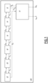
- Figure 1 schematically illustrates a system for controlling the integrity of a railway convoy, indicated by the overall reference number 100.
- FIG. 2 An exemplary railway convoy in the form of a freight train is illustrated in figure 2 and is composed by a driving or leading car 1, and by a plurality of cars 3, 5, 7, 9, 11 and 13 which are disposed in sequence behind the leading car 1.
- the driving car 1 which is constituted for example by a locomotive, includes the cabin of the driver.
- system 100 can be used for controlling any type of railway convoys, namely freight trains, passengers trains, and having any number and type of cars.
- the locomotive at the head of the train will constitute the driving or leading car 1 while the other locomotive at the tail of the convoy will form the ending car; the vice-versa will occur in the opposite travelling direction.
- the system 100 comprises at least:
- At least one wireless transceiver of the plurality of wireless transceivers 12, 14, 16, 18, 20 and 22 is suitable to be installed on each associated car of the plurality of cars 3, 5, 7, 9, 11 and 13.
- each wireless transceiver 12, 14, 16, 18, 20 and 22 is configured to communicate, depending on the position along the railway convoy of the associated car on which it is installed, with the electronic control device 10 and a wireless transceiver of the adjacent following car (if it is the car adjacent to the driving car), or with a wireless transceivers installed on the adjacent preceding car and on the adjacent following car, respectively.
- the electronic control device 10 is configured to communicate in a wireless manner with the transceiver installed on the adjacent car and more in general with all transceivers 12, 14, 16, 18, 20 and 22 installed each on a corresponding car of the railway convoy.
- each car 3, 5, 7, 9, 11 and 13 of the railway convoy is equipped with at least one corresponding transceiver 12, 14, 16, 18, 20 and 22, respectively, which is installed thereon at a desired position, and each transceiver is configured to communicate and to exchange signals, in a wireless manner, with the transceivers installed on the units of the convoy adjacent thereto and/or with the electronic control device 10.
- the transceiver 12, mounted on the first car 3 positioned immediately behind the locomotive 1, is suitable to communicate at least with the electronic control device 10 and with a transceiver 14 installed on the adjacent second car 5 located immediately after the first car 3 itself;
- the transceiver 14 installed on the second car 5 is configured to communicate at least with transceivers 12 and 16 installed on the cars adjacent to the car 5 itself, namely the preceding first car 3 and the following third car 7.
- the wireless electronic control device 10 is configured to initiate a counting of the cars composing the railway convoy by outputting towards the adjacent following car, e.g. in the example illustrated the first car 3 behind the locomotive 1, a counting signal Sc configured to include an updatable value indicating the number of cars currently counted.
- each wireless transceiver 12 is configured, responsive to the counting signal Sc received from the leading car 1 or from the wireless transceiver 12 associated to the adjacent preceding car:
- each transceiver is configured to send back towards the wireless electronic control device 10, a counting-closing signal S FC which includes the current value as ultimately updated by itself if it does not receive said confirmation signal S OK after a predetermined interval of time is elapsed from the instant it has outputted said corresponding counting signal S CUP .
- the counting-closing signal S FC is shown to be sent directly from the wireless transceiver 22 to the wireless electronic control device 10, the counting-closing signal S FC can be actually propagated backwards, car by car, from each car to the adjacent one.
- each wireless transceiver 12, 14, 16, 18, 20 and 22 is configured to include, to said corresponding counting signal S CUP containing the updated current value outputted by it, a pseudo-random code or part.
- each transceiver is equipped with an algorithm which uses polynomial divider additions, thus ensuring higher resilience to possible bit corruptions of the emitted signals or of the transceiver counting device.
- each transceiver outputs its corresponding counting signal S CUP containing the updated current value, which is formed by a fixed part and a variable one, thus resulting in a combination of bits with adequate hamming distances to prevent collision with valid values (pseudo-random).
- the transceiver 20 installed on the fifth car 11 sends back to the transceiver 18 associated to the preceding car 9 the confirmation signal S OK confirming the effective presence of the associated fifth car 11 on which it is installed, updates the current value included in the counting signal received in input by adding the count of its associated car 11, and output towards the transceiver 22 associated to the following sixth car 13 a corresponding counting signal S CUP containing the updated current value, i.e. a value counting all preceding cars plus the own car 11.
- the transceiver 22 sends back to a transceiver 20 associated to the preceding car 11 the confirmation signal S OK confirming the effective presence of the associated sixth car 13 on which it is installed, updates the current value included in the counting signal received in input by adding the count of its associated car 13, and output towards a transceiver associated to a possible following car a corresponding counting signal S CUP containing the updated current value, i.e. a value counting all preceding cars plus the own car 13.
- the transceiver 22 Since in the example illustrated there is not any further car following the sixth car 13, the transceiver 22 does not receive any confirmation signal S OK and, after a predetermined interval of time is elapsed from the instant it has outputted said corresponding counting signal S CUP , sends back towards the electronic control device 10, a counting-closing signal S FC which includes the current value as ultimately updated by itself. This signal is propagated in backward direction through the transceivers of the cars of the railway convoy.
- the fifth car 11 would have constituted the last car of the convoy and its associated transceiver 20 would have issued the counting-closing signal S FC towards the electronic control device 10, after having uselessly waited to receive the confirmation signal S OK for the predetermined interval of time, and having in the end "understood" that the car 11 on which is installed is the last car of the convoy.
- the counting-closing signal S FC is for example transmitted to the electronic control device 10, passing through and being transferred in sequence by the various transceivers installed on the corresponding cars interposed between the last car and the driving car 1.
- the electronic control device 10 is configured to generate, based on the counting-closing signal S FC received, an informing signal S INF for an operator indicative of the number of cars counted currently composing the railway convoy.
- the electronic control device 10 after checking the integrity and freshness of the counting-closing signal S FC received, performs a comparison of the computed result (e.g. the number of cars) with the one validated for example by the driver at start of mission.
- the computed result e.g. the number of cars
- the electronic control device 10 is configured to calculate the current length of the railway convoy based on the counting-closing signal S FC received, and to generate an alarm signal S A for an operator if the calculated length does not correspond to a predefined value.
- Such predefined value is for example the value set by an operator, e.g. the driver, before the railway convoy has entered into service and each time a new journey is started.
- the electronic control device 10 is configured to initiate, automatically or based on an input from an operator, the counting of the cars composing the railway convoy before the railway convoy enters into service.
- the wireless electronic control device 10 periodically sends a "start counting message", setting a counter for example initially equal to "1", being the leading car, e.g. the locomotive.
- This start counting message can encoded using numerical techniques and includes a sequence identifier; the sequence identifier is propagated by the various transceivers and is included in the return messages; it is then used to verify freshness of the answer.
- the system 100 comprises for each car positioned behind the driving car 1, two transceivers.
- the first car 3 comprises two transceivers 12
- the second car 5 comprises two transceivers 14
- the third car 7 comprises two transceivers 16, et cetera up to and including the last car 13 with its two transceivers 22.
- a first transceiver can be positioned at a front part of a respective car, and the second transceiver can be positioned at the rear part thereof; thus, the transceiver positioned at the front part can communicate and exchange signals with the transceiver positioned at the rear part of the preceding car and can simply transfer the signals received to the transceiver positioned at the rear part of the same car.
- the transceiver positioned at a rear part can communicate and exchange signals with the transceiver positioned at the front part of the following car, and can simply transfer the signals received to the transceiver positioned at the front part of the same car.
- all transceivers used are substantially identical to each, at least for the parts/components, including software code, devised for performing the functionalities foreseen for the system 100 according to the present invention.
- each wireless transceiver comprises any suitable processor-based device, e.g. a processor of a type commercially available, suitably programmed and provided to the extent necessary with circuitry, in order to perform the innovative functionalities devised for it within the system 100 according to the present invention.
- processor-based device e.g. a processor of a type commercially available, suitably programmed and provided to the extent necessary with circuitry, in order to perform the innovative functionalities devised for it within the system 100 according to the present invention.
- Each wireless transceiver can be provided with an own antenna, or it is possible to install on each car and in suitable positions, one or more antennas for allowing wireless communications among the various transceivers used and/or with the electronic control device 10 installed on board of the driving car 1.
- each wireless transceiver comprises at least one antenna, in particular at least two antennas.
- Each antenna is configured to receive and transmit signals in full duplex.
- the antennas of a same wireless transceiver can be connected together with a link between them.
- each wireless transceiver used in the system 100 is preferably a device with low power consumption and configure to enter into a sleep mode when not in use.
- it can have its own source of energy, e.g. can be battery-operated or can be connected to an external power source provided on board of the corresponding car on which it is installed.
- the counting signals Sc, the confirmation signals S OK and the counting-closing signal S FC are compliant with the EN50159 standard.
- a first timer or sequence supervision timer is used to determine if the counting sequence is completed in due time.
- This timer can be associated to the electronic control device 10 and its value is close to the polling period which can be set for example between two and five minutes, depending on operational needs and maximum length of a convoy.
- sequence supervision timer In case the sequence supervision timer is over without receiving any return message, the sequence is aborted. Any response received with associated sequence identifier is discarded.
- a second timer or adjacent car timer can be used to determine if an adjacent car is present (and alive); it is associated to a corresponding transceiver and its value is set typically between five and ten seconds. In case no message is received from an adjacent car after sending the polling message, the car is declared as absent and the response message is back propagated up to the electronic control device 10.
- a third timer, or train integrity timer is normally set between two and five times the polling period. Also this timer can be associated to the electronic control device 10. If no message or no valid response is received, starting from the last valid response, the train integrity is declared as lost until next sequence is correctly completed.
- a data packet loss can occur, either during forward propagation or during backward propagation.
- any packet loss is assessed at the car timer, therefore any transceiver is responsible to assess packet loss.
- such loss can occur due to EMC perturbation, or to any intermediate transceiver not properly working, et cetera.
- the train integrity timer is applied before declaring a train integrity loss.
- Figure 3 illustrates a method 200 for controlling the integrity of a railway convoy, such as the railway convoy illustrated in figure 2 , and which comprises at least the following steps:
- the step 250 of outputting towards a transceiver associated to the following car a corresponding counting signal S CUP containing the updated current value comprises including, into the corresponding counting signal S CUP , by each corresponding wireless transceiver, a pseudo-random code or part.
- the method 200 further comprises a step 270 of calculating, by means of the electronic control device 10, the current length of the railway convoy based on the counting-closing signal S FC received and generating at a step 280 an alarm signal S A for an operator if the calculated length does not correspond to a predefined value.
- the method 200 further comprises a step 290 of generating, by means of the electronic control device 10 and based on the counting-closing signal S FC received, an informing signal S INF for an operator indicative of the number of counted cars currently composing the railway convoy.
- said step 220 of initiating the counting comprises initiating automatically or based on an input from an operator the counting of the cars composing the railway convoy before the railway convoy enters into service.
- said step 220 of initiating the counting comprises initiating automatically the counting of the cars periodically during each journey of the railway convoy.
- one or more of the above described timers can be used in the method 200 for performing steps equivalent to the functionalities described in connection with the system 100.
- the system 100 and method 200 according to the present invention allow achieving the intended aim since the control of the actual integrity of a railway convoy can be carried out in an easier and more reliable way with respect to known solutions and in a manner substantially independent from operators that may intervene to modify the composition of a convoy.
- the present invention encompasses also a railway convoy comprising a system 100 as previously described and in particular as defined in the relevant appended claims.
- the system 100 and method 200 thus conceived are susceptible of modifications and variations, all of which are within the scope of the inventive concept as defined in particular by the appended claims; for example, in relation to the specific application, some of the components, e.g. any wireless transceiver can be positioned differently with respect to the exemplary embodiment illustrated, and/or can be provided with additional functionalities if desired.
- the electronic control device 10 can be constituted by or comprise any suitable processor-based device, e.g. a processor of a type commercially available, suitably programmed and provided to the extent necessary with circuitry, in order to perform the innovative functionalities devised for the system 100 according to the present invention. Further the electronic control device 10 can be a device provided ad hoc for the system 100, or a device already used or being part of an board control system used also for scopes and tasks other than those related to the control system 100 previously described.
Landscapes
- Engineering & Computer Science (AREA)
- Mechanical Engineering (AREA)
- Train Traffic Observation, Control, And Security (AREA)
- Electric Propulsion And Braking For Vehicles (AREA)
Abstract
Description
- The present invention relates to a system and a method for controlling the integrity of a railway convoy, and to a railway convoy comprising such system.
- As known, railway convoys, be them for transporting passengers or goods, can have a variable configuration during a journey, i.e. the number of cars or wagons can be modified along the path, even more than once per each journey.
- Therefore, in order to control the integrity of a railway convoy, usually the last wagon is provided with a movable signaling device which is in communication with the cabin of the driver and outputs towards it signals indicative of its position or other relevant data at the end of the convoy.
- In this way, the signaling system can verify the current integrity of the convoy and react accordingly in case of failure; this method requires a check to be carried out before the convoy enters into service, and can be repeated also during each journey.
- However, although this solution allows verifying the actual integrity of the convoy, it entails some aspects which are not completely satisfying.
- In particular, when the composition of a convoy is varied, for example at an intermediate station, then railway operators have to verify that, in the new composition, the wagon initially provided with the signaling device is still the last wagon at the end of the convoy.
- If this is not the case, then the movable signaling device has to be positioned on the new last wagon and operatively reconnected with the cabin of the driver in order to allow the driver to check again the correctness of the current composition of the convoy as ultimately modified.
- Clearly, this procedure is time consuming and in any case, being subject to the intervention of operators, is exposed to possible errors and oversights.
- The present invention is aimed at facing such issues, and in particular at providing a solution capable of monitoring the current integrity of a railway convoy in an easier and more reliable way with respect to the current state of the art.
- This aim is achieved by a system for controlling the integrity of a railway convoy which comprises a driving car and a plurality of cars which are disposed in sequence behind the driving car, the system being characterized in that it comprises at least:
- an electronic control device which is suitable to be installed on the driving car;
- a plurality of wireless transceivers, wherein at least one wireless transceiver of the plurality of wireless transceivers is suitable to be installed on each associated car of the plurality of cars; wherein the electronic control device is configured to initiate a counting of the cars currently composing the railway convoy by sending, towards the following adjacent car, in a wireless manner, a counting signal configured to include an updatable value indicating the number of cars currently counted; and wherein each wireless transceiver is configured, responsive to the counting signal received from the electronic control device or from a wireless transceiver installed on an adjacent preceding car:
- to send back towards a transceiver associated to the preceding car or to the electronic control device a confirmation signal for confirming the effective presence of the associated car on which it is installed;
- to update the current value included in the counting signal received in input by adding the count of its associated car; and
- to output towards a transceiver associated to the following car a corresponding counting signal containing the updated current value;
- According to some embodiments, the system for controlling the integrity of a railway convoy according to the invention may comprise one or more of the following features, which may be combined in any technical feasible combination:
- the electronic control device is configured to calculate the current length of the railway convoy based on the counting-closing signal received and to generate an alarm signal for an operator if the calculated length does not correspond to a predefined value;
- the electronic control device is configured to generate, based on the counting-closing signal received, an informing signal for an operator indicative of the number of counted cars currently composing the railway convoy;
- each wireless transceiver is configured to include, into the corresponding counting signal containing the updated current value outputted by itself, a pseudo-random code or part;
- the electronic control device is configured to initiate automatically or based on an input from an operator, the counting of the cars composing the railway convoy before the railway convoy enters into service;
- the electronic control device is configured to initiate automatically the counting of the cars periodically during each journey of the railway convoy;
- the plurality of wireless transceivers comprise a couple of transceivers suitable to be installed on each associated car of the plurality of cars.
- This aim is also achieved by a method for controlling the integrity of a railway convoy which comprises a driving car and a plurality of cars which are disposed in sequence behind the driving car, the method being characterized in that it comprises at least the following steps:
- installing an electronic control device on board of the driving car and at least one wireless transceiver on board of each associated car of the plurality of cars;
- initiating, by means of the electronic control device, a counting of the cars currently composing the railway convoy by outputting towards the following adjacent car, in a wireless manner, a counting signal configured to include an updatable value indicating the number of cars currently counted; wherein each wireless transceiver is configured, responsive to the counting signal received from the electronic control device or from a wireless transceiver installed on an adjacent preceding car:
- to send back towards a transceiver associated to the preceding car or to the electronic control device a confirmation signal for confirming the effective presence of the associated car on which it is installed;
- to update the current value included in the counting signal received in input by adding the count of its associated car; and
- to output towards a transceiver associated to the following car a corresponding counting signal containing the updated current value; and wherein
- According to some embodiments, the method for controlling the integrity of a railway convoy according to the invention may comprise one or more of the following features, which may be combined in any technical feasible combination:
- the method further comprises:
- calculating, by means of the electronic control device, the current length of the railway convoy based on the counting-closing signal received; and
- generating an alarm signal for an operator if the calculated length does not correspond to a predefined value;
- the method further comprises generating, by means of the electronic control device and based on the counting-closing signal received, an informing signal for an operator indicative of the number of counted cars currently composing the railway convoy;
- the step of outputting towards a transceiver associated to the following car a corresponding counting signal containing the updated current value, comprises including into the corresponding counting signal, by each wireless transceiver, a pseudo-random code or part;
- the step of initiating comprises initiating automatically or based on an input from an operator the counting of the cars composing the railway convoy before the railway convoy enters into service;
- the step of initiating comprises initiating automatically the counting of the cars periodically during each journey of the railway convoy.
- Finally, this aim is also achieved by a railway convoy comprising a system for controlling the integrity of a railway convoy as defined in the appended claims.
- Further characteristics and advantages will become apparent from the description of some preferred but not exclusive exemplary embodiments of a system and method switch according to the present disclosure, illustrated only by way of non-limitative examples with the accompanying drawings, wherein:
-
Figure 1 is a block diagram schematically illustrating a system for controlling the integrity of a railway convoy according to the invention; -
Figure 2 is a view schematically illustrating an example where the system offigure 1 is used for controlling the integrity of a freight train; -
Figure 3 is a flow diagram schematically illustrating a method for controlling the integrity of a railway convoy according to the invention. - It should be noted that in the detailed description that follows, identical or similar components, either from a structural and/or functional point of view, have the same reference numerals, regardless of whether they are shown in different embodiments of the present disclosure; it should also be noted that in order to clearly and concisely describe the present disclosure, the drawings may not necessarily be to scale and certain features of the disclosure may be shown in somewhat schematic form.
- Further, when the term "adapted" or "arranged" or "configured" or "shaped", is used herein while referring to any component as a whole, or to any part of a component, or to a combination of components, it has to be understood that it means and encompasses correspondingly either the structure, and/or configuration and/or form and/or positioning of the related component or part thereof, or combinations, such term refers to.
- In particular, for electronic and/or software means, each of the above listed terms means and encompasses electronic circuits or parts thereof, as well as stored, embedded or running software codes and/or routines, algorithms, or complete programs, suitably designed for achieving the technical result and/or the functional performances for which such means are devised.
- Finally, in the following description and claims, the numeral ordinals first, second, third etc., will be used only for the sake of clarity of description and in no way they should be understood as limiting for whatsoever reason.
-
Figure 1 schematically illustrates a system for controlling the integrity of a railway convoy, indicated by theoverall reference number 100. - An exemplary railway convoy in the form of a freight train is illustrated in
figure 2 and is composed by a driving or leading car 1, and by a plurality ofcars - The driving car 1, which is constituted for example by a locomotive, includes the cabin of the driver.
- Clearly, as it will appear evident from the following description, the
system 100 according to the present invention can be used for controlling any type of railway convoys, namely freight trains, passengers trains, and having any number and type of cars. - For example, with trains having two locomotives positioned at the ends of the convoy, with reference to the travelling direction and from the point of view of the
system 100, the locomotive at the head of the train will constitute the driving or leading car 1 while the other locomotive at the tail of the convoy will form the ending car; the vice-versa will occur in the opposite travelling direction. - Also, if there is a locomotive located in an intermediate position along the railway convoy, e.g. in case of a convoy formed by two trains that have to run a certain part of the journey together and then be split for different destinations, then such intermediate locomotive will form and be considered by the
system 100 as one of the various cars behind the leading car 1. - As illustrated in
figure 1 , thesystem 100 according to the invention comprises at least: - an electronic control device or
controller 10 which is suitable to be installed on the driving car 1; and - a plurality of
wireless transceivers - In particular, at least one wireless transceiver of the plurality of
wireless transceivers cars - Usefully, each
wireless transceiver electronic control device 10 and a wireless transceiver of the adjacent following car (if it is the car adjacent to the driving car), or with a wireless transceivers installed on the adjacent preceding car and on the adjacent following car, respectively. - Also, the
electronic control device 10 is configured to communicate in a wireless manner with the transceiver installed on the adjacent car and more in general with alltransceivers - In practice, each
car corresponding transceiver electronic control device 10. - More in detail, for example the
transceiver 12, mounted on the first car 3 positioned immediately behind the locomotive 1, is suitable to communicate at least with theelectronic control device 10 and with atransceiver 14 installed on the adjacent second car 5 located immediately after the first car 3 itself; thetransceiver 14 installed on the second car 5 is configured to communicate at least withtransceivers - The same applies to all cars forming in sequence the railway convoy and equipped each with at least one corresponding wireless transceiver.
- In the
system 100 according to the invention, the wirelesselectronic control device 10 is configured to initiate a counting of the cars composing the railway convoy by outputting towards the adjacent following car, e.g. in the example illustrated the first car 3 behind the locomotive 1, a counting signal Sc configured to include an updatable value indicating the number of cars currently counted. - In turn, each
wireless transceiver 12 is configured, responsive to the counting signal Sc received from the leading car 1 or from thewireless transceiver 12 associated to the adjacent preceding car: - to send back towards a transceiver associated to the preceding car or to the electronic control device 10 a confirmation signal SOK for confirming the effective presence of the associated car on which it is installed;
- to update the current value included in the counting signal Sc received in input by adding the count of its associated car; and
- to output towards a transceiver associated to the following car a corresponding counting signal SCUP containing the updated current value.
- Further, each transceiver is configured to send back towards the wireless
electronic control device 10, a counting-closing signal SFC which includes the current value as ultimately updated by itself if it does not receive said confirmation signal SOK after a predetermined interval of time is elapsed from the instant it has outputted said corresponding counting signal SCUP. Advantageously, though the counting-closing signal SFC is shown to be sent directly from thewireless transceiver 22 to the wirelesselectronic control device 10, the counting-closing signal SFC can be actually propagated backwards, car by car, from each car to the adjacent one. - According to a possible embodiment, each
wireless transceiver - In practice, for the sake of substantially increasing computational safety, each transceiver is equipped with an algorithm which uses polynomial divider additions, thus ensuring higher resilience to possible bit corruptions of the emitted signals or of the transceiver counting device.
- Accordingly, every time the counting of the cars is performed, each transceiver outputs its corresponding counting signal SCUP containing the updated current value, which is formed by a fixed part and a variable one, thus resulting in a combination of bits with adequate hamming distances to prevent collision with valid values (pseudo-random).
- Hence, when a transceiver will count a certain value, for example "three", at each counting cycle the value "three", which remains valid provided that the relevant car is in the same position, would correspond to a digital signal composed differently in its entirety but the part expressing the counted true value three will be the same.
- In practice, with reference to the exemplary railway convoy illustrated in
figures 1 and2 , and considering for the sake of conciseness in more details only the last two cars, namely thefifth car 11 and the last (sixth)car 13, after the wirelesselectronic control device 10 has initiated the counting by outputting towards the first car 3 the counting signal Sc, and once thetransceivers transceiver 20 installed on thefifth car 11. - Then, the
transceiver 20 installed on thefifth car 11 sends back to thetransceiver 18 associated to the preceding car 9 the confirmation signal SOK confirming the effective presence of the associatedfifth car 11 on which it is installed, updates the current value included in the counting signal received in input by adding the count of its associatedcar 11, and output towards thetransceiver 22 associated to the following sixth car 13 a corresponding counting signal SCUP containing the updated current value, i.e. a value counting all preceding cars plus theown car 11. - This latest corresponding counting signal SCUP is thus received in input by the
transceiver 22 installed on thesixth car 13. - The
transceiver 22 sends back to atransceiver 20 associated to the precedingcar 11 the confirmation signal SOK confirming the effective presence of the associatedsixth car 13 on which it is installed, updates the current value included in the counting signal received in input by adding the count of its associatedcar 13, and output towards a transceiver associated to a possible following car a corresponding counting signal SCUP containing the updated current value, i.e. a value counting all preceding cars plus theown car 13. - Since in the example illustrated there is not any further car following the
sixth car 13, thetransceiver 22 does not receive any confirmation signal SOK and, after a predetermined interval of time is elapsed from the instant it has outputted said corresponding counting signal SCUP, sends back towards theelectronic control device 10, a counting-closing signal SFC which includes the current value as ultimately updated by itself. This signal is propagated in backward direction through the transceivers of the cars of the railway convoy. - Clearly, if the
sixth car 13 were not present, then thefifth car 11 would have constituted the last car of the convoy and its associatedtransceiver 20 would have issued the counting-closing signal SFC towards theelectronic control device 10, after having uselessly waited to receive the confirmation signal SOK for the predetermined interval of time, and having in the end "understood" that thecar 11 on which is installed is the last car of the convoy. - The counting-closing signal SFC is for example transmitted to the
electronic control device 10, passing through and being transferred in sequence by the various transceivers installed on the corresponding cars interposed between the last car and the driving car 1. - In one possible embodiment, the
electronic control device 10 is configured to generate, based on the counting-closing signal SFC received, an informing signal SINF for an operator indicative of the number of cars counted currently composing the railway convoy. - In particular, in one possible embedment, the
electronic control device 10, after checking the integrity and freshness of the counting-closing signal SFC received, performs a comparison of the computed result (e.g. the number of cars) with the one validated for example by the driver at start of mission. - In yet a further embodiment, the
electronic control device 10 is configured to calculate the current length of the railway convoy based on the counting-closing signal SFC received, and to generate an alarm signal SA for an operator if the calculated length does not correspond to a predefined value. - Such predefined value is for example the value set by an operator, e.g. the driver, before the railway convoy has entered into service and each time a new journey is started.
- In a possible embodiment, the
electronic control device 10 is configured to initiate, automatically or based on an input from an operator, the counting of the cars composing the railway convoy before the railway convoy enters into service. - Conveniently, according to a possible embodiment, the wireless
electronic control device 10 periodically sends a "start counting message", setting a counter for example initially equal to "1", being the leading car, e.g. the locomotive. This start counting message can encoded using numerical techniques and includes a sequence identifier; the sequence identifier is propagated by the various transceivers and is included in the return messages; it is then used to verify freshness of the answer. - In yet a further embodiment, and as illustrated in
figure 2 , thesystem 100 according to the invention comprises for each car positioned behind the driving car 1, two transceivers. - Thus, as for example illustrated in
figure 2 , the first car 3 comprises twotransceivers 12, the second car 5 comprises twotransceivers 14, the third car 7 comprises twotransceivers 16, et cetera up to and including thelast car 13 with its twotransceivers 22. - According to this embodiment, for each couple of transmitters installed on board of a car, a first transceiver can be positioned at a front part of a respective car, and the second transceiver can be positioned at the rear part thereof; thus, the transceiver positioned at the front part can communicate and exchange signals with the transceiver positioned at the rear part of the preceding car and can simply transfer the signals received to the transceiver positioned at the rear part of the same car. In turn, the transceiver positioned at a rear part can communicate and exchange signals with the transceiver positioned at the front part of the following car, and can simply transfer the signals received to the transceiver positioned at the front part of the same car.
- In one possible embodiment, all transceivers used, either if only one transceiver per car is installed or also when two transceivers per car are used, are substantially identical to each, at least for the parts/components, including software code, devised for performing the functionalities foreseen for the
system 100 according to the present invention. - In particular, each wireless transceiver comprises any suitable processor-based device, e.g. a processor of a type commercially available, suitably programmed and provided to the extent necessary with circuitry, in order to perform the innovative functionalities devised for it within the
system 100 according to the present invention. - Each wireless transceiver can be provided with an own antenna, or it is possible to install on each car and in suitable positions, one or more antennas for allowing wireless communications among the various transceivers used and/or with the
electronic control device 10 installed on board of the driving car 1. - For instance, each wireless transceiver comprises at least one antenna, in particular at least two antennas. Each antenna is configured to receive and transmit signals in full duplex. In case a wireless transceiver comprises at least two antennas, the antennas of a same wireless transceiver can be connected together with a link between them.
- Further, each wireless transceiver used in the
system 100 is preferably a device with low power consumption and configure to enter into a sleep mode when not in use. In addition, it can have its own source of energy, e.g. can be battery-operated or can be connected to an external power source provided on board of the corresponding car on which it is installed. - Advantageously, the counting signals Sc, the confirmation signals SOK and the counting-closing signal SFC are compliant with the EN50159 standard.
- Conveniently, in order to increase safety and reliability of counting, in some possible embodiments of the
system 100, there could be used up to three main timers, out of which a first timer or sequence supervision timer is used to determine if the counting sequence is completed in due time. This timer can be associated to theelectronic control device 10 and its value is close to the polling period which can be set for example between two and five minutes, depending on operational needs and maximum length of a convoy. - In case the sequence supervision timer is over without receiving any return message, the sequence is aborted. Any response received with associated sequence identifier is discarded.
- A second timer or adjacent car timer can be used to determine if an adjacent car is present (and alive); it is associated to a corresponding transceiver and its value is set typically between five and ten seconds. In case no message is received from an adjacent car after sending the polling message, the car is declared as absent and the response message is back propagated up to the
electronic control device 10. - A third timer, or train integrity timer is normally set between two and five times the polling period. Also this timer can be associated to the
electronic control device 10. If no message or no valid response is received, starting from the last valid response, the train integrity is declared as lost until next sequence is correctly completed. - During operations, a data packet loss can occur, either during forward propagation or during backward propagation. In particular, any packet loss is assessed at the car timer, therefore any transceiver is responsible to assess packet loss.
- In general, in case of a packet lost, a new packet sequence is sent; in case of many lost sequences, the train integrity is defined as compromised.
- For example, such loss can occur due to EMC perturbation, or to any intermediate transceiver not properly working, et cetera.
- Thus depending on the cases, either no response is received by the wireless electronic control device 10 (expiration of sequence supervision timer) or a wrong response (less cars are counted) is received by wireless
electronic control device 10. - In both cases, the train integrity timer is applied before declaring a train integrity loss.
-
Figure 3 illustrates amethod 200 for controlling the integrity of a railway convoy, such as the railway convoy illustrated infigure 2 , and which comprises at least the following steps: - 210: installing an electronic control device, such as the
electronic control device 10, on board of the driving car 1, and at least onewireless transceiver cars - 220: initiating, by means of the
electronic control device 10, a counting of the cars currently composing the railway convoy by outputting towards the following adjacent car 3, in a wireless manner, a counting signal Sc configured to include an updatable value indicating the number of cars currently counted;
wherein eachwireless transceiver electronic control device 10 or from a wireless transceiver installed on an adjacent preceding car: - 230: to send back to a transceiver associated to the preceding car or to the electronic control device 10 a confirmation signal SOK for confirming the effective presence of the associated car on which it is installed;
- 240: to update the current value included in the counting signal Sc received in input by adding the count of its associated car; and
- 250: to output towards a transceiver associated to the following car a corresponding counting signal SCUP containing the updated current value; and wherein each transceiver is further configured (at step 260) to send back towards the
electronic control device 10, a counting-closing signal SFC which includes the current value as ultimately updated by itself if it does not receive said confirmation signal SOK after a predetermined interval of time is elapsed from the instant it has outputted said corresponding counting signal SCUP. - In particular, the
step 250 of outputting towards a transceiver associated to the following car a corresponding counting signal SCUP containing the updated current value, comprises including, into the corresponding counting signal SCUP, by each corresponding wireless transceiver, a pseudo-random code or part. - In one possible embodiment, the
method 200 further comprises astep 270 of calculating, by means of theelectronic control device 10, the current length of the railway convoy based on the counting-closing signal SFC received and generating at astep 280 an alarm signal SA for an operator if the calculated length does not correspond to a predefined value. - In yet a further embodiment, the
method 200 further comprises astep 290 of generating, by means of theelectronic control device 10 and based on the counting-closing signal SFC received, an informing signal SINF for an operator indicative of the number of counted cars currently composing the railway convoy. - In a possible embodiment, said
step 220 of initiating the counting comprises initiating automatically or based on an input from an operator the counting of the cars composing the railway convoy before the railway convoy enters into service. - According to a further possible embodiment, said
step 220 of initiating the counting comprises initiating automatically the counting of the cars periodically during each journey of the railway convoy. - Also, one or more of the above described timers can be used in the
method 200 for performing steps equivalent to the functionalities described in connection with thesystem 100. Hence, it is evident from the foregoing description that thesystem 100 andmethod 200 according to the present invention allow achieving the intended aim since the control of the actual integrity of a railway convoy can be carried out in an easier and more reliable way with respect to known solutions and in a manner substantially independent from operators that may intervene to modify the composition of a convoy. - These results are achieved according to a solution quite easy to be realized and installed, and can be used in new railway convoys as well as for retrofitting those already in service.
- Hence, the present invention encompasses also a railway convoy comprising a
system 100 as previously described and in particular as defined in the relevant appended claims. - The
system 100 andmethod 200 thus conceived are susceptible of modifications and variations, all of which are within the scope of the inventive concept as defined in particular by the appended claims; for example, in relation to the specific application, some of the components, e.g. any wireless transceiver can be positioned differently with respect to the exemplary embodiment illustrated, and/or can be provided with additional functionalities if desired. Theelectronic control device 10 can be constituted by or comprise any suitable processor-based device, e.g. a processor of a type commercially available, suitably programmed and provided to the extent necessary with circuitry, in order to perform the innovative functionalities devised for thesystem 100 according to the present invention. Further theelectronic control device 10 can be a device provided ad hoc for thesystem 100, or a device already used or being part of an board control system used also for scopes and tasks other than those related to thecontrol system 100 previously described. - All the details may furthermore be replaced with technically equivalent elements.
Claims (14)
- System (100) for controlling the integrity of a railway convoy which comprises a driving car (1) and a plurality of cars (3, 5, 7, 9, 11, 13) which are disposed in sequence behind the driving car (1), the system (100) being characterized in that it comprises at least:- an electronic control device (10) which is suitable to be installed on the driving car (1);- a plurality of wireless transceivers (12, 14, 16, 18, 20, 22), wherein at least one wireless transceiver of the plurality of wireless transceivers is suitable to be installed on each associated car of the plurality of cars (3, 5, 7, 9, 11, 13); whereinthe electronic control device (10) is configured to initiate a counting of the cars currently composing the railway convoy by sending, towards the following adjacent car (3), in a wireless manner, a counting signal (Sc) configured to include an updatable value indicating the number of cars currently counted; and whereineach wireless transceiver (12, 14, 16, 18, 20, 22) is configured, responsive to the counting signal (Sc) received from the electronic control device (10) or from a wireless transceiver installed on an adjacent preceding car:- to send back towards a transceiver associated to the preceding car or to the electronic control device (10) a confirmation signal (SOK) for confirming the effective presence of the associated car on which it is installed;- to update the current value included in the counting signal (Sc) received in input by adding the count of its associated car; and- to output towards a transceiver associated to the following car a corresponding counting signal (SCUP) containing the updated current value;
and wherein each transceiver is further configured to send back towards the electronic control device (10), a counting-closing signal (SFC) which includes the current value as ultimately updated by itself if it does not receive said confirmation signal (SOK) after a predetermined interval of time is elapsed from the instant it has outputted said corresponding counting signal (SCUP). - System (100) according to claim 1, wherein the electronic control device (10) is configured to calculate the current length of the railway convoy based on the counting-closing signal (SFC) received and to generate an alarm signal (SA) for an operator if the calculated length does not correspond to a predefined value.
- System (100) according to claim 1 or 2, wherein the electronic control device (10) is configured to generate, based on the counting-closing signal (SFC) received, an informing signal (SINF) for an operator indicative of the number of counted cars currently composing the railway convoy.
- System (100) according to one or more of the previous claims, wherein each wireless transceiver (12, 16, 16, 18, 20, 22) is configured to include, into the corresponding counting signal (SCUP) containing the updated current value outputted by itself, a pseudo-random code or part.
- System (100) according to one or more of the previous claims, wherein the electronic control device (10) is configured to initiate automatically or based on an input from an operator, the counting of the cars composing the railway convoy before the railway convoy enters into service.
- System (100) according to one or more of the previous claims, wherein the electronic control device (10) is configured to initiate automatically the counting of the cars periodically during each journey of the railway convoy.
- System (100) according to one or more of the previous claims, wherein the plurality of wireless transceivers (12, 14, 16, 18, 20, 22) comprise a couple of transceivers suitable to be installed on each associated car of the plurality of cars (3, 5, 7, 9, 11, 13).
- A railway convoy comprising a system (100) according to one or more of the preceding claims.
- A method (200) for controlling the integrity of a railway convoy which comprises a driving car (1) and a plurality of cars (3, 5, 7, 9, 11, 13) which are disposed in sequence behind the driving car (1), the method (200) being characterized in that it comprises at least the following steps:- (210): installing an electronic control device (10) on board of the driving car (1) and at least one wireless transceiver (12, 14, 16, 18, 20, 22) on board of each associated car of the plurality of cars (3, 5, 7, 9, 11, 13);- (220): initiating, by means of the electronic control device (10), a counting of the cars currently composing the railway convoy by outputting towards the following adjacent car (3), in a wireless manner, a counting signal (Sc) configured to include an updatable value indicating the number of cars currently counted;
wherein each wireless transceiver (12, 14, 16, 18, 20, 22) is configured, responsive to the counting signal (Sc) received from the electronic control device (10) or from a wireless transceiver installed on an adjacent preceding car:- (230): to send back towards a transceiver associated to the preceding car or to the electronic control device (10) a confirmation signal (SOK) for confirming the effective presence of the associated car on which it is installed;- (240): to update the current value included in the counting signal (Sc) received in input by adding the count of its associated car; and- (250): to output towards a transceiver associated to the following car a corresponding counting signal (SCUP) containing the updated current value; and wherein- (260): each transceiver is further configured to send back towards the electronic control device (10), a counting-closing signal (SFC) which includes the current value as ultimately updated by itself if it does not receive said confirmation signal (SOK) after a predetermined interval of time is elapsed from the instant it has outputted said corresponding counting signal (SCUP). - The method (200) according to claim 9, wherein it further comprises:- (270) calculating, by means of the electronic control device (10), the current length of the railway convoy based on the counting-closing signal (SFC) received; and- (280) generating an alarm signal (SA) for an operator if the calculated length does not correspond to a predefined value.
- The method (200) according to claim 9 or 10, wherein it further comprises (290) generating, by means of the electronic control device (10) and based on the counting-closing signal (SFC) received, an informing signal (SINF) for an operator indicative of the number of counted cars currently composing the railway convoy.
- The method (200) according to one or more of the claims 9 to 11, wherein said step (250) of outputting towards a transceiver associated to the following car a corresponding counting signal (SCUP) containing the updated current value, comprises including into the corresponding counting signal (SCUP), by each wireless transceiver, a pseudo-random code or part.
- The method (200) according to one or more of the claims 9 to 12, wherein said step (220) of initiating comprises initiating automatically or based on an input from an operator the counting of the cars composing the railway convoy before the railway convoy enters into service.
- The method (200) according to one or more of the claims 9 to 13, wherein said step (220) of initiating comprises initiating automatically the counting of the cars periodically during each journey of the railway convoy.
Priority Applications (2)
| Application Number | Priority Date | Filing Date | Title |
|---|---|---|---|
| EP23305604.3A EP4450363A1 (en) | 2023-04-19 | 2023-04-19 | System and method for controlling the integrity of a railway convoy, and railway convoy comprising such system |
| AU2024202434A AU2024202434A1 (en) | 2023-04-19 | 2024-04-15 | System and method for controlling the integrity of a railway convoy, and railway convoy comprising such system |
Applications Claiming Priority (1)
| Application Number | Priority Date | Filing Date | Title |
|---|---|---|---|
| EP23305604.3A EP4450363A1 (en) | 2023-04-19 | 2023-04-19 | System and method for controlling the integrity of a railway convoy, and railway convoy comprising such system |
Publications (1)
| Publication Number | Publication Date |
|---|---|
| EP4450363A1 true EP4450363A1 (en) | 2024-10-23 |
Family
ID=86329132
Family Applications (1)
| Application Number | Title | Priority Date | Filing Date |
|---|---|---|---|
| EP23305604.3A Pending EP4450363A1 (en) | 2023-04-19 | 2023-04-19 | System and method for controlling the integrity of a railway convoy, and railway convoy comprising such system |
Country Status (2)
| Country | Link |
|---|---|
| EP (1) | EP4450363A1 (en) |
| AU (1) | AU2024202434A1 (en) |
Citations (2)
| Publication number | Priority date | Publication date | Assignee | Title |
|---|---|---|---|---|
| EP3000688A1 (en) * | 2014-09-26 | 2016-03-30 | Siemens Rail Automation S.A.U. | System and method for checking the integrity of a multi-unit vehicle |
| KR20200115879A (en) * | 2019-03-28 | 2020-10-08 | 한국철도공사 | Automatic Wireless Train Protection System based on LTE-R and Method thereof |
-
2023
- 2023-04-19 EP EP23305604.3A patent/EP4450363A1/en active Pending
-
2024
- 2024-04-15 AU AU2024202434A patent/AU2024202434A1/en active Pending
Patent Citations (2)
| Publication number | Priority date | Publication date | Assignee | Title |
|---|---|---|---|---|
| EP3000688A1 (en) * | 2014-09-26 | 2016-03-30 | Siemens Rail Automation S.A.U. | System and method for checking the integrity of a multi-unit vehicle |
| KR20200115879A (en) * | 2019-03-28 | 2020-10-08 | 한국철도공사 | Automatic Wireless Train Protection System based on LTE-R and Method thereof |
Also Published As
| Publication number | Publication date |
|---|---|
| AU2024202434A1 (en) | 2024-11-07 |
Similar Documents
| Publication | Publication Date | Title |
|---|---|---|
| US8626058B2 (en) | Method and apparatus related to on-board message repeating for vehicle consist communications system | |
| US10967888B2 (en) | On-board apparatus and ground system | |
| US8264330B2 (en) | Systems and method for communicating data in a railroad system | |
| US7038597B2 (en) | Railroad distributed power communication system and method | |
| CA2562742A1 (en) | On-board message repeater for railroad train communications system | |
| EA024596B1 (en) | Method and apparatus related to on-board message repeating for vehicle consist communications system | |
| AU2016397695B2 (en) | Distributed power remote communication status system and method | |
| JP5827509B2 (en) | Wireless train control system | |
| US20130206487A1 (en) | Method and device for determining the train length of a plurality of coupled railway traction vehicles | |
| US20230415798A1 (en) | System for verifying the integrity of a convoy, particularly a railway convoy | |
| AU2024202434A1 (en) | System and method for controlling the integrity of a railway convoy, and railway convoy comprising such system | |
| JP5306083B2 (en) | Automatic train control device and train control method | |
| US6535803B1 (en) | Supply of data to motor vehicles | |
| US11352036B2 (en) | Terminal protection apparatus and terminal protection method | |
| JP6270504B2 (en) | Train radio system | |
| AU2018203821B2 (en) | Method and apparatus related to on-board message repeating for vehicle consist communications system | |
| US20220410948A1 (en) | Method and device for monitoring the configuration of a train | |
| JP2003040110A (en) | On-board automatic train control system | |
| JP5436632B2 (en) | Automatic train control device and train control method | |
| GB1082027A (en) | Vehicle control installations | |
| CN120397009A (en) | A platform door control system | |
| JP2024099315A (en) | Train Control System | |
| WO2025099892A1 (en) | Wireless train control system and wireless train control method | |
| KR100354973B1 (en) | Method and system for transmitting railroad information |
Legal Events
| Date | Code | Title | Description |
|---|---|---|---|
| PUAI | Public reference made under article 153(3) epc to a published international application that has entered the european phase |
Free format text: ORIGINAL CODE: 0009012 |
|
| STAA | Information on the status of an ep patent application or granted ep patent |
Free format text: STATUS: THE APPLICATION HAS BEEN PUBLISHED |
|
| STAA | Information on the status of an ep patent application or granted ep patent |
Free format text: STATUS: REQUEST FOR EXAMINATION WAS MADE |
|
| AK | Designated contracting states |
Kind code of ref document: A1 Designated state(s): AL AT BE BG CH CY CZ DE DK EE ES FI FR GB GR HR HU IE IS IT LI LT LU LV MC ME MK MT NL NO PL PT RO RS SE SI SK SM TR |
|
| 17P | Request for examination filed |
Effective date: 20241003 |
|
| RBV | Designated contracting states (corrected) |
Designated state(s): AL AT BE BG CH CY CZ DE DK EE ES FI FR GB GR HR HU IE IS IT LI LT LU LV MC ME MK MT NL NO PL PT RO RS SE SI SK SM TR |