EP4450324A1 - Flow rate control method, flow rate control device, and cooling system - Google Patents
Flow rate control method, flow rate control device, and cooling system Download PDFInfo
- Publication number
- EP4450324A1 EP4450324A1 EP22907422.4A EP22907422A EP4450324A1 EP 4450324 A1 EP4450324 A1 EP 4450324A1 EP 22907422 A EP22907422 A EP 22907422A EP 4450324 A1 EP4450324 A1 EP 4450324A1
- Authority
- EP
- European Patent Office
- Prior art keywords
- battery
- heating medium
- temperature
- flow rate
- cooling water
- Prior art date
- Legal status (The legal status is an assumption and is not a legal conclusion. Google has not performed a legal analysis and makes no representation as to the accuracy of the status listed.)
- Pending
Links
- 238000000034 method Methods 0.000 title claims description 90
- 238000001816 cooling Methods 0.000 title claims description 53
- 238000007599 discharging Methods 0.000 claims abstract description 83
- 238000010438 heat treatment Methods 0.000 claims abstract description 57
- 238000006243 chemical reaction Methods 0.000 claims abstract description 17
- 239000000498 cooling water Substances 0.000 claims description 240
- 230000007246 mechanism Effects 0.000 claims description 18
- 239000002826 coolant Substances 0.000 claims description 7
- XLYOFNOQVPJJNP-UHFFFAOYSA-N water Substances O XLYOFNOQVPJJNP-UHFFFAOYSA-N 0.000 description 23
- 230000006870 function Effects 0.000 description 17
- 239000000112 cooling gas Substances 0.000 description 11
- 238000012546 transfer Methods 0.000 description 10
- 239000003990 capacitor Substances 0.000 description 7
- 230000000694 effects Effects 0.000 description 7
- 230000008569 process Effects 0.000 description 6
- 239000007789 gas Substances 0.000 description 5
- 238000010586 diagram Methods 0.000 description 4
- 238000012986 modification Methods 0.000 description 4
- 230000004048 modification Effects 0.000 description 4
- 238000009499 grossing Methods 0.000 description 3
- 230000020169 heat generation Effects 0.000 description 3
- 230000007423 decrease Effects 0.000 description 2
- 238000009434 installation Methods 0.000 description 2
- 238000012545 processing Methods 0.000 description 2
- WHXSMMKQMYFTQS-UHFFFAOYSA-N Lithium Chemical compound [Li] WHXSMMKQMYFTQS-UHFFFAOYSA-N 0.000 description 1
- 230000015556 catabolic process Effects 0.000 description 1
- 238000002485 combustion reaction Methods 0.000 description 1
- 238000004891 communication Methods 0.000 description 1
- 230000003247 decreasing effect Effects 0.000 description 1
- 238000013461 design Methods 0.000 description 1
- 230000005611 electricity Effects 0.000 description 1
- 230000002708 enhancing effect Effects 0.000 description 1
- 239000012530 fluid Substances 0.000 description 1
- 230000017525 heat dissipation Effects 0.000 description 1
- 230000006872 improvement Effects 0.000 description 1
- 238000010348 incorporation Methods 0.000 description 1
- 229910052744 lithium Inorganic materials 0.000 description 1
- 229910052987 metal hydride Inorganic materials 0.000 description 1
- 230000009467 reduction Effects 0.000 description 1
- 230000001172 regenerating effect Effects 0.000 description 1
- 230000008929 regeneration Effects 0.000 description 1
- 238000011069 regeneration method Methods 0.000 description 1
- 238000004904 shortening Methods 0.000 description 1
- 230000001629 suppression Effects 0.000 description 1
Images






Classifications
-
- B—PERFORMING OPERATIONS; TRANSPORTING
- B60—VEHICLES IN GENERAL
- B60L—PROPULSION OF ELECTRICALLY-PROPELLED VEHICLES; SUPPLYING ELECTRIC POWER FOR AUXILIARY EQUIPMENT OF ELECTRICALLY-PROPELLED VEHICLES; ELECTRODYNAMIC BRAKE SYSTEMS FOR VEHICLES IN GENERAL; MAGNETIC SUSPENSION OR LEVITATION FOR VEHICLES; MONITORING OPERATING VARIABLES OF ELECTRICALLY-PROPELLED VEHICLES; ELECTRIC SAFETY DEVICES FOR ELECTRICALLY-PROPELLED VEHICLES
- B60L58/00—Methods or circuit arrangements for monitoring or controlling batteries or fuel cells, specially adapted for electric vehicles
- B60L58/10—Methods or circuit arrangements for monitoring or controlling batteries or fuel cells, specially adapted for electric vehicles for monitoring or controlling batteries
- B60L58/24—Methods or circuit arrangements for monitoring or controlling batteries or fuel cells, specially adapted for electric vehicles for monitoring or controlling batteries for controlling the temperature of batteries
- B60L58/25—Methods or circuit arrangements for monitoring or controlling batteries or fuel cells, specially adapted for electric vehicles for monitoring or controlling batteries for controlling the temperature of batteries by controlling the electric load
-
- B—PERFORMING OPERATIONS; TRANSPORTING
- B60—VEHICLES IN GENERAL
- B60L—PROPULSION OF ELECTRICALLY-PROPELLED VEHICLES; SUPPLYING ELECTRIC POWER FOR AUXILIARY EQUIPMENT OF ELECTRICALLY-PROPELLED VEHICLES; ELECTRODYNAMIC BRAKE SYSTEMS FOR VEHICLES IN GENERAL; MAGNETIC SUSPENSION OR LEVITATION FOR VEHICLES; MONITORING OPERATING VARIABLES OF ELECTRICALLY-PROPELLED VEHICLES; ELECTRIC SAFETY DEVICES FOR ELECTRICALLY-PROPELLED VEHICLES
- B60L1/00—Supplying electric power to auxiliary equipment of vehicles
- B60L1/003—Supplying electric power to auxiliary equipment of vehicles to auxiliary motors, e.g. for pumps, compressors
-
- B—PERFORMING OPERATIONS; TRANSPORTING
- B60—VEHICLES IN GENERAL
- B60L—PROPULSION OF ELECTRICALLY-PROPELLED VEHICLES; SUPPLYING ELECTRIC POWER FOR AUXILIARY EQUIPMENT OF ELECTRICALLY-PROPELLED VEHICLES; ELECTRODYNAMIC BRAKE SYSTEMS FOR VEHICLES IN GENERAL; MAGNETIC SUSPENSION OR LEVITATION FOR VEHICLES; MONITORING OPERATING VARIABLES OF ELECTRICALLY-PROPELLED VEHICLES; ELECTRIC SAFETY DEVICES FOR ELECTRICALLY-PROPELLED VEHICLES
- B60L50/00—Electric propulsion with power supplied within the vehicle
- B60L50/10—Electric propulsion with power supplied within the vehicle using propulsion power supplied by engine-driven generators, e.g. generators driven by combustion engines
- B60L50/16—Electric propulsion with power supplied within the vehicle using propulsion power supplied by engine-driven generators, e.g. generators driven by combustion engines with provision for separate direct mechanical propulsion
-
- B—PERFORMING OPERATIONS; TRANSPORTING
- B60—VEHICLES IN GENERAL
- B60L—PROPULSION OF ELECTRICALLY-PROPELLED VEHICLES; SUPPLYING ELECTRIC POWER FOR AUXILIARY EQUIPMENT OF ELECTRICALLY-PROPELLED VEHICLES; ELECTRODYNAMIC BRAKE SYSTEMS FOR VEHICLES IN GENERAL; MAGNETIC SUSPENSION OR LEVITATION FOR VEHICLES; MONITORING OPERATING VARIABLES OF ELECTRICALLY-PROPELLED VEHICLES; ELECTRIC SAFETY DEVICES FOR ELECTRICALLY-PROPELLED VEHICLES
- B60L58/00—Methods or circuit arrangements for monitoring or controlling batteries or fuel cells, specially adapted for electric vehicles
- B60L58/10—Methods or circuit arrangements for monitoring or controlling batteries or fuel cells, specially adapted for electric vehicles for monitoring or controlling batteries
- B60L58/24—Methods or circuit arrangements for monitoring or controlling batteries or fuel cells, specially adapted for electric vehicles for monitoring or controlling batteries for controlling the temperature of batteries
- B60L58/26—Methods or circuit arrangements for monitoring or controlling batteries or fuel cells, specially adapted for electric vehicles for monitoring or controlling batteries for controlling the temperature of batteries by cooling
-
- B—PERFORMING OPERATIONS; TRANSPORTING
- B60—VEHICLES IN GENERAL
- B60L—PROPULSION OF ELECTRICALLY-PROPELLED VEHICLES; SUPPLYING ELECTRIC POWER FOR AUXILIARY EQUIPMENT OF ELECTRICALLY-PROPELLED VEHICLES; ELECTRODYNAMIC BRAKE SYSTEMS FOR VEHICLES IN GENERAL; MAGNETIC SUSPENSION OR LEVITATION FOR VEHICLES; MONITORING OPERATING VARIABLES OF ELECTRICALLY-PROPELLED VEHICLES; ELECTRIC SAFETY DEVICES FOR ELECTRICALLY-PROPELLED VEHICLES
- B60L58/00—Methods or circuit arrangements for monitoring or controlling batteries or fuel cells, specially adapted for electric vehicles
- B60L58/10—Methods or circuit arrangements for monitoring or controlling batteries or fuel cells, specially adapted for electric vehicles for monitoring or controlling batteries
- B60L58/24—Methods or circuit arrangements for monitoring or controlling batteries or fuel cells, specially adapted for electric vehicles for monitoring or controlling batteries for controlling the temperature of batteries
- B60L58/27—Methods or circuit arrangements for monitoring or controlling batteries or fuel cells, specially adapted for electric vehicles for monitoring or controlling batteries for controlling the temperature of batteries by heating
-
- B—PERFORMING OPERATIONS; TRANSPORTING
- B60—VEHICLES IN GENERAL
- B60L—PROPULSION OF ELECTRICALLY-PROPELLED VEHICLES; SUPPLYING ELECTRIC POWER FOR AUXILIARY EQUIPMENT OF ELECTRICALLY-PROPELLED VEHICLES; ELECTRODYNAMIC BRAKE SYSTEMS FOR VEHICLES IN GENERAL; MAGNETIC SUSPENSION OR LEVITATION FOR VEHICLES; MONITORING OPERATING VARIABLES OF ELECTRICALLY-PROPELLED VEHICLES; ELECTRIC SAFETY DEVICES FOR ELECTRICALLY-PROPELLED VEHICLES
- B60L9/00—Electric propulsion with power supply external to the vehicle
- B60L9/16—Electric propulsion with power supply external to the vehicle using AC induction motors
- B60L9/18—Electric propulsion with power supply external to the vehicle using AC induction motors fed from DC supply lines
-
- B—PERFORMING OPERATIONS; TRANSPORTING
- B60—VEHICLES IN GENERAL
- B60L—PROPULSION OF ELECTRICALLY-PROPELLED VEHICLES; SUPPLYING ELECTRIC POWER FOR AUXILIARY EQUIPMENT OF ELECTRICALLY-PROPELLED VEHICLES; ELECTRODYNAMIC BRAKE SYSTEMS FOR VEHICLES IN GENERAL; MAGNETIC SUSPENSION OR LEVITATION FOR VEHICLES; MONITORING OPERATING VARIABLES OF ELECTRICALLY-PROPELLED VEHICLES; ELECTRIC SAFETY DEVICES FOR ELECTRICALLY-PROPELLED VEHICLES
- B60L2240/00—Control parameters of input or output; Target parameters
- B60L2240/40—Drive Train control parameters
- B60L2240/42—Drive Train control parameters related to electric machines
- B60L2240/425—Temperature
-
- B—PERFORMING OPERATIONS; TRANSPORTING
- B60—VEHICLES IN GENERAL
- B60L—PROPULSION OF ELECTRICALLY-PROPELLED VEHICLES; SUPPLYING ELECTRIC POWER FOR AUXILIARY EQUIPMENT OF ELECTRICALLY-PROPELLED VEHICLES; ELECTRODYNAMIC BRAKE SYSTEMS FOR VEHICLES IN GENERAL; MAGNETIC SUSPENSION OR LEVITATION FOR VEHICLES; MONITORING OPERATING VARIABLES OF ELECTRICALLY-PROPELLED VEHICLES; ELECTRIC SAFETY DEVICES FOR ELECTRICALLY-PROPELLED VEHICLES
- B60L2240/00—Control parameters of input or output; Target parameters
- B60L2240/40—Drive Train control parameters
- B60L2240/52—Drive Train control parameters related to converters
- B60L2240/525—Temperature of converter or components thereof
-
- B—PERFORMING OPERATIONS; TRANSPORTING
- B60—VEHICLES IN GENERAL
- B60L—PROPULSION OF ELECTRICALLY-PROPELLED VEHICLES; SUPPLYING ELECTRIC POWER FOR AUXILIARY EQUIPMENT OF ELECTRICALLY-PROPELLED VEHICLES; ELECTRODYNAMIC BRAKE SYSTEMS FOR VEHICLES IN GENERAL; MAGNETIC SUSPENSION OR LEVITATION FOR VEHICLES; MONITORING OPERATING VARIABLES OF ELECTRICALLY-PROPELLED VEHICLES; ELECTRIC SAFETY DEVICES FOR ELECTRICALLY-PROPELLED VEHICLES
- B60L2240/00—Control parameters of input or output; Target parameters
- B60L2240/40—Drive Train control parameters
- B60L2240/54—Drive Train control parameters related to batteries
- B60L2240/545—Temperature
-
- B—PERFORMING OPERATIONS; TRANSPORTING
- B60—VEHICLES IN GENERAL
- B60L—PROPULSION OF ELECTRICALLY-PROPELLED VEHICLES; SUPPLYING ELECTRIC POWER FOR AUXILIARY EQUIPMENT OF ELECTRICALLY-PROPELLED VEHICLES; ELECTRODYNAMIC BRAKE SYSTEMS FOR VEHICLES IN GENERAL; MAGNETIC SUSPENSION OR LEVITATION FOR VEHICLES; MONITORING OPERATING VARIABLES OF ELECTRICALLY-PROPELLED VEHICLES; ELECTRIC SAFETY DEVICES FOR ELECTRICALLY-PROPELLED VEHICLES
- B60L53/00—Methods of charging batteries, specially adapted for electric vehicles; Charging stations or on-board charging equipment therefor; Exchange of energy storage elements in electric vehicles
- B60L53/20—Methods of charging batteries, specially adapted for electric vehicles; Charging stations or on-board charging equipment therefor; Exchange of energy storage elements in electric vehicles characterised by converters located in the vehicle
Definitions
- the present invention relates to a flow rate control method, a flow rate control device, and a cooling system for controlling a flow rate of a heating medium.
- This battery system includes a battery pack, charge/discharge means, heat exchanging means, transfer means, and a control device.
- the battery pack is configured by energizably connecting a plurality of battery cells.
- the charge/discharge means is connected to the battery pack in a wired manner, and executes ripple charging and discharging that alternately charges and discharges for multiple times in one second with the battery pack.
- the heat exchanging means is provided such that the heat generated from the charge/discharge means and a heat transfer medium exchange heat.
- the transfer means transfers the heat transfer medium toward the battery pack.
- the control device controls respective operations of the charge/discharge means and the transfer means.
- the control device controls the operation of the charge/discharge means such that the ripple charging and discharging is executed, and further controls the operation of the transfer means such that the heat transfer medium, which receives the heat generated from the charge/discharge means, is transferred to the battery pack.
- Patent Document 1 Japanese Unexamined Patent Application Publication No. 2010-257722
- the prior art has a problem that efficient temperature rise in a battery is difficult because the heat generated in the battery is emitted outside by heat exchange between the battery and the heat transfer medium while ripple charging and discharging is executed.
- the present invention aims to achieve an object to provide a flow rate control method, a flow rate control device, and a cooling system that allow efficiently raising a temperature of a battery by ripple charging and discharging.
- the present invention in a vehicle on which a motor that drives the vehicle, a battery that allows supplying an electric power to the motor, and a power conversion device disposed between the motor and the battery are mounted, outputs an execution command of ripple charging and discharging that alternately charges and discharges for multiple times with the battery to the power conversion device when a temperature of the battery is lower than a predetermined threshold temperature, and controls the flow rate of the heating medium such that the flow rate of the heating medium is reduced compared with a case where the temperature of the battery is lower than the temperature of the heating medium when the temperature of the battery is higher than the temperature of the heating medium that exchanges heat with the battery while the ripple charging and discharging is executed, which solves the above-described problem.
- the present invention allows efficiently raising the temperature of the battery by ripple charging and discharging.
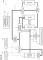
- FIG. 1 is a configuration schematic diagram of a cooling system 100 according to a first embodiment.
- the cooling system 100 is a system that is mounted on an electric-powered vehicle, and is for cooling a driving battery 1, a motor 2, an inverter 3, and an on board charger 6, which are described later.
- the description is made by using what is called an electric vehicle (EV) that does not include an internal combustion engine, such as a gasoline engine or a diesel engine, but includes the driving battery 1, the inverter 3 that converts an electric power of the driving battery 1, and the motor 2 that generates a driving power that drives the electric-powered vehicle by the electric power output from the inverter 3 as an example for the electric-powered vehicle.
- EV electric vehicle
- the cooling system 100 includes the driving battery 1, the motor 2, the inverter 3, a DC-DC converter 4, an auxiliary machine battery 5, and the on board charger 6 electrically connected by a wiring harness or a busbar.
- the inverter 3 is disposed between the driving battery 1 and the motor 2, and the DC-DC converter 4 and the on board charger 6 are connected to a wiring harness that connects between the driving battery 1 and the inverter 3.
- the auxiliary machine battery 5 is connected to the DC-DC converter 4.
- the cooling system 100 includes a flow rate control device 20 that includes a controller 21. The flow rate control device 20 will be described later.
- the cooling system 100 is provided with a cooling water flow passage 11 as a passage for cooling water.
- the cooling water is described as an example of a heating medium that exchanges heat among the driving battery 1, the inverter 3, the motor 2, and the on board charger 6.
- the cooling water flow passage 11 is provided with a chiller 12, a radiator 15, a valve A to valve C, and a pump A. So as to be able to cool the driving battery 1, the inverter 3, the motor 2, and the on board charger 6 as cooling targets, the cooling water flow passage 11 is provided near the respective configurations.
- the positioning method or the installation method of the cooling water flow passage 11 is not specifically limited, but the cooling water flow passage 11 is provided for the cooling targets by an installation method or a positioning method known as of the filing of the present application.
- the cooling water flow passage 11 is configured such that the cooling water is allowed to circulate by open/close control of a valve by the flow rate control device 20 described later.
- the driving battery 1 is configured to be able to supply an electric power to the motor 2 that is a traveling driving source of the electric vehicle.
- a battery pack configured of a nickel-metal hydride secondary battery, a lithium secondary battery, or the like is used.
- the battery pack is a collective body of a plurality of battery cells connected in series, and has a predetermined internal resistance.
- a ripple current is input from the inverter 3.
- the ripple current is a current having a charge and discharge pattern alternately repeating charging and discharging in a pulse shape. Once the ripple current is input to the driving battery 1, charging and discharging corresponding to the ripple current is alternately repeated, and the current by the charging and discharging flows to an internal resistance.
- the driving battery 1 is disposed with a temperature sensor (not illustrated) for detecting a temperature of the driving battery 1.
- the temperature of the driving battery 1 detected by the temperature sensor is output to the flow rate control device 20.
- the driving battery 1 corresponds to an exemplary battery of the present invention.
- the motor 2 is a driving motor that generates a torque for driving driving wheels of the electric vehicle.
- the motor 2 generates a driving power by an AC power supplied from the inverter 3, and the generated driving power is transferred to the driving wheels via a reduction gear, which is not illustrated.
- the motor 2 rotates as a regenerative driving power is transmitted to the motor 2 from the driving wheels.
- the rotation of the motor 2 outputs an AC power from the motor 2 to the inverter 3.
- a three-phase AC motor is used for the motor 2, for example, a three-phase AC motor is used.
- the motor 2 corresponds to an exemplary motor of the present invention.
- the inverter 3 is a power conversion device that converts a DC power input from the driving battery 1 into an AC power, and outputs the converted AC power to the motor 2. As described above, when an AC power is output from the motor 2 to the inverter 3, the inverter 3 also functions as a power conversion device that converts an AC power from the motor 2 into a DC power, and outputs the converted DC power to the driving battery 1.
- the inverter 3 is electrically connected to the flow rate control device 20, and operates corresponding to a control signal from the controller 21.
- the inverter 3 is configured of circuits connected to switching elements, such as IGBTs, in a bridged manner, and the circuits allow two-phase to three-phase conversion.
- the inverter 3 is configured of three pairs of series circuits (also referred to as three pairs of arm circuits) to which two switching elements are connected in series.
- the three pairs of series circuits are connected to the driving battery 1 in parallel.
- respective connection points between switching elements of upper arms and switching elements of lower arms are connected to output terminals of respective phases (U-phase, V-phase, and W-phase) on the motor 2 side.
- the inverter 3 has a smoothing capacitor (not illustrated).
- the smoothing capacitor is a capacitor for making an input/output voltage of the driving battery 1 smooth.
- the smoothing capacitor is connected between the three pairs of series circuits and the connecting terminals of the driving battery 1.
- an electric circuit such as a gate driver, that converts the control signal from the controller 21 into a control signal for the switching elements by raising the voltage to an operating voltage of the switching elements that configure the inverter 3 may be provided between the controller 21 and the inverter 3.
- the inverter 3 corresponds to an exemplary power conversion device of the present invention.
- the DC-DC converter 4 decreases the voltage of the driving battery 1, and outputs the decreased voltage to the auxiliary machine battery 5.
- the auxiliary machine battery 5 is a battery for supplying an electric power to each auxiliary machine (each load) mounted on the electric vehicle.
- the auxiliary machine battery 5 is charged by an electric power from the DC-DC converter 4.
- the on board charger 6 is a device that operates when the driving battery 1 is charged by a power feeding facility disposed outside the electric vehicle.
- a power feeding facility configured to correspond to a normal charging method
- a power feeding facility configured to correspond to a rapid charging method.
- the normal charging method is a method of charging the driving battery 1 using a power source of a single-phase alternate current of 100 V or 200 V.
- the rapid charging method is a method of charging the driving battery 1 using a power source of three phase of 200 V.
- the rapid charging method is able to charge to a full charge in a short time compared with the normal charging method.
- the on board charger 6 is used to charge the driving battery 1 by the normal charging method.
- the on board charger 6 is electrically connected to a charging port of the electric vehicle.
- a charging cable of the power feeding facility is connected to the charging port of the electric vehicle, and once the electric power from the power feeding facility is supplied, the AC power from the power feeding facility is input to the on board charger 6.
- the on board charger 6 converts the input AC power to a DC power, and outputs the converted DC power to the driving battery 1.
- the on board charger 6 corresponds to an exemplary on board charger of the present invention.
- the chiller 12, a compressor 13, and a capacitor 14 configure a cooling circuit driven by, for example, the auxiliary machine battery 5.
- the cooling circuit has a cooling gas flow passage that allows a cooling gas to circulate as illustrated in FIG. 1 .
- the compressor 13 compresses the cooling gas and discharges the compressed cooling gas having a high temperature and a high pressure.
- the capacitor 14 exchanges heat between the compressed cooling gas and the cooling gas flowing in the cooling gas flow passage, emits the heat of the compressed cooling gas, thus cooling down the compressed cooling gas.
- the chiller 12 is a device for cooling down the cooling water before the heat exchange is performed with the driving battery 1.
- the chiller 12 is disposed between the on board charger 6 and the driving battery 1 in the cooling water flow passage 11.
- the chiller 12 exchanges heat between the cooling gas flowing in the cooling gas flow passage and the cooling water flowing in the cooling water flow passage 11, absorbs the heat of the cooling water flowing in the cooling water flow passage 11, thus cooling down the cooling water.
- a control signal is input to the chiller 12 from the controller 21, and the chiller 12 operates or stops corresponding to the control signal.
- the chiller 12 operates, the cooling water flowed from the on board charger 6 side is cooled down as described above.
- the chiller 12 stops the cooling water flowed from the on board charger 6 side is not cooled down.
- the valve A is disposed between the chiller 12 and the driving battery 1 in the cooling water flow passage 11.
- the valve A is electrically connected to the flow rate control device 20, and opens and closes corresponding to the control signal from the controller 21.
- the valve A opens in accordance with the control signal from the controller 21, the cooling water that has passed the chiller 12 is transmitted to the driving battery 1.
- the valve A closes in accordance with the control signal from the controller 21 the cooling water is not transmitted to the driving battery 1.
- the valve B is disposed in a branch passage branching between the on board charger 6 and the chiller 12 in the cooling water flow passage 11.
- the branch passage where the valve B is disposed is the cooling water flow passage 11 that branches from the main stream between the on board charger 6 and the chiller 12, and joins to the main stream between the driving battery 1 and the pump A.
- the valve B is a bypassing valve not for transmitting the cooling water to the driving battery 1 but for transmitting the cooling water to the other devices.
- the valve B is electrically connected to the flow rate control device 20, and opens and closes corresponding to the control signal from the controller 21.
- valve B When the valve B opens in accordance with the control signal from the controller 21, the cooling water is transmitted to the pump A from the on board charger 6. On the other hand, when the valve B closes in accordance with the control signal from the controller 21, the cooling water from the on board charger 6 is not transmitted to the pump A.
- the valve A and the valve B correspond to exemplary valves of the present invention.
- the pump A is a water pump for transmitting the cooling water to the cooling water flow passage 11.
- the pump A is disposed between the driving battery 1 with the valve B and the radiator 15 with the valve C in the cooling water flow passage 11.
- the pump A is electrically connected to the flow rate control device 20, and operates or stops corresponding to the control signal from the controller 21.
- the pump A operates in accordance with the control signal from the controller 21, the cooling water sent out of the pump A is transmitted to the valve C after being cooled down by the radiator 15.
- the pump A stops in accordance with the control signal from the controller 21 the cooling water is not sent out of the pump A, and the cooling water does not flow in the cooling water flow passage 11.
- the pump A functions as transfer means for the cooling water in the cooling water flow passage 11.
- the radiator 15 is a device for cooling down the cooling water before heat exchange is performed between the motor 2 and the inverter 3.
- the radiator 15 is disposed between the pump A and the motor 2 with the inverter 3 in the cooling water flow passage 11.
- the radiator 15 is operated by a predetermined control device, and the cooling water transmitted from the pump A is cooled down by the radiator 15.
- the valve C has a function of controlling a water flow rate of the radiator output side. Specifically, the valve C controls the water flow rate of the radiator 15 so as not to let the water that has passed through the radiator perform cooling until the temperature of the water of the motor 2 and the inverter 3 increases to a predetermined water temperature. That is, the valve C has a function equal to that of a thermostat of an engine radiator. Therefore, the valve C controls a water quantity of the radiator 15 with a water temperature at an inlet of the inverter 3 or at an outlet of the valve C being a target value (for example, stops only the water of the radiator or reduces the water quantity).
- the valve C opens to cause the water of the radiator 15 to flow.
- the water temperature at the inlet of the inverter 3 is less than 40°C, the water of the radiator 15 is stopped (passing water to the radiator 15 is stopped) to decrease the water temperature drop at the inlet of the inverter 3.
- the flow rate control device 20 includes the controller 21 allowing to achieve the flow rate control method of the present invention.
- the controller 21 is configured as an electronic control unit made of a computer including hardware and software.
- the computer of the controller 21 is configured of a ROM (Read Only Memory) for executing warming-up control, cooling-down control, and flow rate control, a CPU (Central Processing Unit) executing programs stored in this ROM, and a RAM (Random Access Memory) functioning as an accessible storage device.
- ROM Read Only Memory
- CPU Central Processing Unit
- RAM Random Access Memory
- MPU Micro Processing Unit
- DSP Digital Signal Processor
- ASIC Application Specific Integrated Circuit
- FPGA Field Programmable Gate Array
- the flow rate control device 20 corresponds to an exemplary flow rate control device of the present invention.
- the controller 21 controls the inverter 3 such that the ripple charging and discharging that repeats charging and discharging for multiple times in the driving battery 1 is executed by the warming-up function when a warming-up request is input.
- the warming-up request is a signal for raising the temperature of the driving battery 1 by ripple charging and discharging.
- the warming-up request is input to the controller 21 at least when the temperature of the driving battery 1 is lower than a predetermined warming-up target threshold (unit: temperature).
- the warming-up target threshold is a temperature determined in advance, and is, for example, 10°C.
- the controller 21 obtains the temperature of the driving battery 1 from a temperature sensor detecting the temperature of the driving battery 1.
- the controller 21 compares the temperature of the driving battery 1 with the warming-up target threshold, and when the temperature of the driving battery 1 is lower than the warming-up target threshold, the controller 21 generates a control signal for ripple charging and discharging that turns on or off the switching elements that configure the inverter 3 by pulse-width modulation system.
- the control signal for ripple charging and discharging is a control signal for flowing a ripple current in a pulse shape alternately repeating charging and discharging at a predetermined cycle to the driving battery 1 from the inverter 3.
- a method for generating the control signal for ripple charging and discharging will be described.
- a pulse-width modulation system that generates a gate driving signal for the switching element based on a comparison between a three-phase alternating-current voltage command value and a carrier wave (carrier).
- the controller 21 compares carrier waves having phases corresponding to the respective phases of the motor 2, not the same carrier waves with no phase differences, with the three-phase alternating-current voltage value, and generates control signals for ripple charging and discharging to the switching elements of the respective phases.
- the controller 21 sets a phase difference of 180 degrees between a carrier wave (carrier wave A) as a comparison target of an alternating-current voltage command value of the U-phase and a carrier wave (carrier wave B) as a comparison target of an alternating-current voltage command value of the V-phase and the W-phase.
- the controller 21, then, generates a control signal for ripple charging and discharging to the switching element of the U-phase based on the comparison between the alternating-current voltage command value of the U-phase and the carrier wave A.
- the controller 21 also generates a control signal for ripple charging and discharging to the switching element of the V-phase based on the comparison between the alternating-current voltage command value of the V-phase and the carrier wave B, and generates a control signal for ripple charging and discharging to the switching element of the W-phase based on the comparison between the alternating-current voltage command value of the W-phase and the carrier wave B.
- the carrier wave A and the carrier wave B having the phase difference of 180 degrees as described above are merely an example, and the phase difference between the carrier waves is not limited to 180 degrees. In order to obtain the above-described effect, it is only necessary that the carrier waves have two or more phases of the motor 2 differing from one another.
- the controller 21 outputs the control signal for ripple charging and discharging to the inverter 3 as an execution command to the inverter 3. This causes the inverter 3 to repeatedly turning on and off the switching elements of the respective phases by the control signal for ripple charging and discharging, and the ripple current flows from the inverter 3 to the driving battery 1.
- the warming-up request is input, the case where the temperature of the driving battery 1 is lower than the warming-up target threshold has been described, but the configuration in which, when the state of the electric vehicle satisfies a predetermined condition in addition to the temperature condition of the driving battery 1, the warming-up request is input to the controller 21, may be employed.
- the state of the electric vehicle for performing the ripple charging and discharging includes at least any one of the state of charging the driving battery 1 from a power feeding facility provided outside the electric vehicle, the state where the electric vehicle is stopped with the ignition switch turned on, and the state where the ignition switch is turned off and the warming-up switch is turned on.
- the warming-up switch is a switch that is provided in the vehicle and can be operated by a passenger for warming-up the driving battery 1. When the electric vehicle is in any state of these states, and the temperature of the driving battery 1 is lower than the warming-up target threshold, the warming-up request is input to the controller 21, and the controller 21 controls the inverter 3 by warming-up function.
- the cooling-down threshold is a temperature higher than the above-described warming-up target threshold.
- the cooling-down threshold is a temperature determined in advance, and is, for example, 40°C.
- the controller 21 compares the temperature of the driving battery 1 with the cooling-down threshold, and when the temperature of the driving battery 1 is higher than the cooling-down threshold, the control signal for operating the chiller 12 is output to the chiller 12.
- the flow rate control function is a function for controlling the flow rate of the cooling water flowing in the cooling water flow passage 11.
- the controller 21 reduces the flow rate of the cooling water to the driving battery 1 compared with the case where the temperature of the driving battery 1 is lower than the temperature of the cooling water by controlling opening and closing of the valve A and the valve B.
- the cooling water to be transmitted to the driving battery 1 is a cooling water before exchanging heat with the driving battery 1 (hereinafter, also referred to as the cooling water before heat exchange with the driving battery 1). In the example in FIG.
- the cooling water before heat exchange with the driving battery 1 is a cooling water flowing in the cooling water flow passage 11 between the chiller 12 and the driving battery 1.
- a water temperature sensor (not illustrated) that detects the temperature of the cooling water is disposed between the chiller 12 and the valve A in the cooling water flow passage 11. The temperature of the cooling water before heat exchange with the driving battery 1 detected by the water temperature sensor is output to the flow rate control device 20. Note that the water temperature sensor may be disposed between the valve A and the driving battery 1 in the cooling water flow passage 11.
- the controller 21 controls opening and closing of the valve A and the valve B such that the inverter 3 and the cooling water exchange heat and the motor 2 and the cooling water exchange heat while the ripple charging and discharging is executed.
- the controller 21 controls opening and closing the valve A and the valve B such that any of the flow rates of the flow rate of the cooling water that exchanges heat with the inverter 3 and the flow rate of the cooling water that exchanges heat with the motor 2 is increased more than the flow rate of the cooling water before heat exchange with the driving battery 1.
- the flow rate of the cooling water that exchanges heat with the motor 2 and the flow rate of the cooling water that exchanges heat with the inverter 3 each fail to be independently controlled, and therefore, the flow rate of the cooling water that exchanges heat with the motor 2 and the flow rate of the cooling water that exchanges heat with the inverter 3 are substantially equal.
- the target that is increased more than the flow rate of the cooling water before heat exchange with the driving battery 1 by the controller 21 is any of the flow rates of the flow rate of the cooling water that exchanges heat with the inverter 3 and the flow rate of the cooling water that exchanges heat with the motor 2.
- the flow rate of the cooling water that exchanges heat with the motor 2 and the flow rate of the cooling water that exchanges heat with the inverter 3 are controllable in a manner independent of one another.
- the controller 21 controls opening and closing of the valve A and the valve B such that a sum of the flow rate of the cooling water that exchanges heat with the inverter 3 and the flow rate of the cooling water that exchanges heat with the motor 2 is increased more than the flow rate of the cooling water before heat exchange with the driving battery 1.
- the controller 21 controls opening and closing of the valve A and the valve B such that the cooling water that has received the heat generated by the inverter 3 and the cooling water that has received the heat generated from the motor 2 exchange heat with the driving battery 1.
- the controller 21 controls opening and closing of the valve A and the valve B such that the cooling water is circulated to exchange heat with each of the devices.
- FIG. 2 is an exemplary timing chart for describing the flow rate control method of the cooling water.
- FIG. 2 illustrates each of states of temperatures (the temperature of the driving battery 1, the temperature of the cooling water before heat exchange with the driving battery 1), an open/close state of the valve A, an open/close state of valve B, an operation state of the pump A, an input/output current of the driving battery 1, a cooling water amount of the driving battery 1, a cooling water amount of the motor 2 and the inverter 3, a vehicle speed of the electric vehicle, and a parking lock of the electric vehicle from the top.
- the horizontal axes indicate time.
- the parking lock mechanism is a mechanism for locking a gear in a gear box, and is a mechanism that makes an axle shaft as an output shaft unrotatable.
- the gear box is provided on the axle shaft connecting right and left driving wheels.
- Time t 0 the temperature of the driving battery 1 is lower than the warming-up target threshold. Since it is in the state where the temperature of the driving battery 1 is lower than the warming-up target threshold and the vehicle is stopped, the warming-up request is input to the controller 21, and the controller 21 outputs the control signal for ripple charging and discharging to the inverter 3.
- Time t 0 is the time at which the ripple charging and discharging is started in the driving battery 1.
- the controller 21 outputs the control signal for operating the pump A to the pump A and sends out the cooling water to the cooling water flow passage 11.
- the controller 21 outputs the control signal for closing the valve A to the valve A and outputs the control signal for opening the valve B to the valve B.
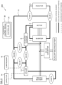
- FIG. 3A is a drawing illustrating a state where the cooling water does not flow to the driving battery 1 in the cooling system 100 illustrated in FIG. 1 .
- the valve A When the valve A is closed and the valve B is opened, as illustrated in FIG. 3A , after being cooled down by the radiator 15, the cooling water sent out of the pump A circulates the cooling water flow passage 11 in the order from the inverter 3, the motor 2, the on board charger 6, and the pump A. Meanwhile, since the valve A is closed, the cooling water is not transmitted to the driving battery 1, thus, no cooling water flows in the driving battery 1.
- the controller 21 obtains the temperature of the driving battery 1 from the temperature sensor that detects the temperature of the driving battery 1 and obtains the temperature of the cooling water before heat exchange with the driving battery 1 from the water temperature sensor disposed between the chiller 12 and the valve A.
- the driving battery 1 From Time to to Time t 1 , the driving battery 1 has heat generated inside thereof by the ripple charging and discharging, and the temperature of the driving battery 1 is increased. That is, the warming-up control of the driving battery 1 by the ripple charging and discharging is executed.
- the switching element In the inverter 3, the switching element is repeatedly turned on and off for ripple charging and discharging, and therefore, the inverter 3 generates heat.
- the current caused by the ripple current flows in the motor 2, and the motor 2 generates heat.
- the cooling water before exchanging heat with the driving battery 1 is warmed by the heat generated by the inverter 3 and the motor 2, and thus, the temperature of the cooling water before heat exchange with the driving battery 1 is also increased.
- the controller 21 From Time to to Time t 1 , since the temperature of the driving battery 1 is higher than the temperature of the cooling water before heat exchange with the driving battery 1, the controller 21 outputs the control signal for closing the valve A to the valve A and outputs the control signal for opening the valve B to the valve B. From Time to to Time t 1 , as illustrated in FIG. 3 (A) , the cooling water does not flow in the driving battery 1.
- the temperature of the cooling water before heat exchange with the driving battery 1 is higher than the temperature of the driving battery 1.
- the controller 21 outputs the control signal for opening the valve A to the valve A and outputs the control signal for closing the valve B to the valve B.
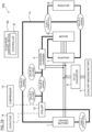
- FIG. 3B is a drawing illustrating a state where the cooling water flows in the driving battery 1 in the cooling system 100 illustrated in FIG. 1 .
- the valve A When the valve A is opened and the valve B is closed, as illustrated in FIG. 3B , after being cooled down by the radiator 15, the cooling water sent out of the pump A circulates in the cooling water flow passage 11 in the order from the inverter 3, the motor 2, the on board charger 6, the driving battery 1, and the pump A. Since the valve A is opened, the cooling water is transmitted to the driving battery 1, thus, the cooling water flows in the driving battery 1.
- the controller 21 outputs the control signal for opening the valve A to the valve A and outputs the control signal for closing the valve B to the valve B. From Time t 1 to Time t 2 , as illustrated in FIG. 3B , the cooling water flows in the driving battery 1.
- the temperature of the driving battery 1 is higher than the temperature of the cooling water before heat exchange with the driving battery 1.
- the controller 21 outputs the control signal for closing the valve A to the valve A and outputs the control signal for opening the valve B to the valve B.
- the cooling water is not transmitted to the driving battery 1, and therefore, no cooling water flows in the driving battery 1.
- the controller 21 From Time t 2 to Time t 3 , since the temperature of the driving battery 1 is higher than the temperature of the cooling water before heat exchange with the driving battery 1, the controller 21 outputs the control signal for closing the valve A to the valve A and outputs the control signal for opening the valve B to the valve B. From Time t 2 to Time t 3 , as illustrated in FIG. 3A , no cooling water flows in the driving battery 1.
- the controller 21 stops outputting the control signal for ripple charging and discharging to the inverter 3 as a stop command of the ripple charging and discharging.
- the controller 21 outputs the control signal for stopping the pump A to the pump A.
- the stop of the pump A causes no cooling water to flow in the driving battery 1, the motor 2, or the inverter 3.
- the reason of no cooling water flowing in the cooling water flow passage 11 is based on the aspect that there is no cause of heat generation in the driving battery 1, the motor 2, or the inverter 3 as there is no necessity of the ripple charging and discharging and the electric vehicle is stopped.
- the controller 21 outputs the control signal for operating the pump A to the pump A.
- the controller 21 outputs the control signal for opening the valve A to the valve A and outputs the control signal for closing the valve B to the valve B.
- the cooling water sent out of the pump A circulates in the cooling water flow passage 11 in the order from the inverter 3, the motor 2, the on board charger 6, the driving battery 1, and the pump A.
- the driving battery 1, the motor 2, and the inverter 3 that generate heat in association with the traveling of the electric vehicle can be cooled down.
- the temperature of the driving battery 1 reaches the cooling-down threshold.
- the cooling-down request is input to the controller 21, and the controller 21 outputs the control signal for operating the chiller 12 to the chiller 12. This cools down the cooling water before heat exchange with the driving battery 1 and accelerates the cooling down of the driving battery 1. Note that the parking lock is turned on and the electric vehicle is again stopped at Time t 5 .
- FIG. 4 is an exemplary flowchart illustrating the flow rate control method of the cooling water according to the embodiment. The flowchart illustrated in FIG. 4 is executed at each predetermined cycle by the controller 21.
- the controller 21 determines whether there is a cooling-down request of the driving battery 1 or not.
- the cooling-down request of the driving battery 1 is input to the controller 21 at least when the temperature of the driving battery 1 is higher than the predetermined cooling-down threshold.
- the procedure proceeds to Step S8, and when the cooling-down request is not input to the controller 21, the procedure proceeds to Step S2.
- the controller 21 determines whether the electric vehicle is stopped or not. For example, the controller 21 obtains a signal indicating the operation state of the parking lock mechanism from another control device that controls the operation of the parking lock mechanism to determine whether the parking lock is turned on or off. When it is determined that the parking lock is turned on and the vehicle is stopped, the procedure proceeds to Step S3, and when it is determined that the parking lock is turned off and the vehicle is not stopped, the procedure proceeds to Step S9.
- the controller 21 compares the temperature of the driving battery 1 with the warming-up target threshold, and determines whether the temperature of the driving battery 1 is lower than the warming-up target threshold or not.
- the timing at which the temperature of the driving battery 1 is obtained from the temperature sensor is not limited, the controller 21 may obtain the temperature of the driving battery 1 from the temperature sensor at Step S3 or may obtain the temperature of the driving battery 1 from the temperature sensor before Step S3.
- the procedure proceeds to Step S4
- Step S9 when the warming-up request is not input to the controller 21.
- Step S4 the controller 21 outputs the control signal for ripple charging and discharging to the inverter 3 as an execution command of the ripple charging and discharging.
- the switching element is repeatedly turned on and off corresponding to the control signal for ripple charging and discharging, and the ripple current for alternately charging and discharging for multiple times is output from the inverter 3 to the driving battery 1.
- the controller 21 obtains the temperature of the cooling water before heat exchange with the driving battery 1 from the water temperature sensor.
- Step S6 the controller 21 compares the temperature of the driving battery 1 with the temperature of the cooling water before heat exchange with the driving battery 1 obtained at Step S5, and determines whether the temperature of the driving battery 1 is higher than the temperature of the cooling water before heat exchange with the driving battery 1 or not.
- Step S7 the procedure proceeds to Step S7, and when a negative determination is made by the controller 21, the procedure proceeds to Step S9.
- Step S7 the controller 21 outputs the control signal for closing the valve A to the valve A and outputs the control signal for opening the valve B to the valve B.
- closing the valve A causes no cooling water to flow in the driving battery 1.
- opening the valve B causes the cooling water to flow in the inverter 3, the motor 2, and the on board charger 6.
- the controller 21 terminates the process of the flowchart illustrated in FIG. 4 .
- Step S8 the controller 21 outputs the control signal for operating the chiller 12 to the chiller 12.
- Step S9 the procedure proceeds to Step S9.
- Step S9 the controller 21 outputs the control signal for opening the valve A to the valve A and outputs the control signal for closing the valve B to the valve B.
- opening the valve A causes the cooling water to flow in the driving battery 1.
- the cooling water sent out of the pump A circulates in the cooling water flow passage 11 in the order of the inverter 3, the motor 2, the on board charger 6, the driving battery 1, and the pump A.
- the controller 21 terminates the process of the flowchart illustrated in FIG. 4 .
- the temperature of the driving battery 1 is lower than the predetermined warming-up target threshold, the execution command of ripple charging and discharging that alternately charges and discharges for multiple times with the driving battery 1 is output to the inverter 3, and when the temperature of the driving battery 1 is higher than the temperature of the cooling water that exchanges heat with the driving battery 1 while the ripple charging and discharging is executed, the flow rate of the cooling water is reduced compared with the case where the temperature of the driving battery 1 is lower than the temperature of the cooling water.
- the temperature of the driving battery 1 can be efficiently raised by the ripple charging and discharging.
- the temperature rise rate of the driving battery 1 is increased, and the inputtable/outputtable electric power of the driving battery 1 can be increased promptly from a low temperature state.
- shortening of the charging time by the rapid charging method may be attempted.
- the chargeable power of the driving battery 1 by regeneration at deceleration is increased, and therefore, improvement in electricity cost performance of the driving battery 1 may be attempted.
- the electric vehicle includes the cooling water flow passage 11, and the valves A, B, and the pump A disposed in the cooling water flow passage 11.
- the controller 21 controls opening and closing of the valve A and the valve B, and thus, reduces the flow rate of the cooling water when the temperature of the driving battery 1 is higher than the temperature of the cooling water exchanging heat with the driving battery 1 while the ripple charging and discharging is executed, compared with the case where the temperature of the driving battery 1 is lower than the temperature of the cooling water.
- the simple method of open/close control of the valves allows efficiently raising the temperature of the driving battery 1 by ripple charging and discharging. Since it is achievable by installing the valve A and the valve B in the cooling water flow passage 11, suppression of enlargement of the cooling system 100 may be achieved.
- the cooling water flow passage 11 is a flow passage through which the cooling water that exchanges heat with the driving battery 1, the cooling water that exchanges heat with the inverter 3, and the cooling water that exchanges heat with the motor 2 are allowed to circulate.
- the controller 21 controls opening and closing of the valve A and the valve B such that the inverter 3 and the cooling water exchange heat and the motor 2 and the cooling water exchange heat while the ripple charging and discharging is executed. This enables the heat generated in the motor 2 and the inverter 3 by ripple charging and discharging to be emitted in the cooling water thus allowing cooling down the motor 2 and the inverter 3. As the result, the possibility of breakdown of the motor 2 and the inverter 3 caused by heat may be reduced.
- the controller 21 controls opening and closing of the valve A and the valve B such that any flow rate of the flow rate of the cooling water that exchanges heat with the inverter 3 and the flow rate of the cooling water that exchanges heat with the motor 2 is increased more than the flow rate of the cooling water before heat exchange with the driving battery 1 when the temperature of the driving battery 1 is higher than the temperature of the cooling water before heat exchange with the driving battery 1 while the ripple charging and discharging is executed.
- This allows suppressing or reducing the emission of the heat generated in the driving battery 1 to the cooling water, also allows emitting the heat generated in the motor 2 and the inverter 3 to the cooling water.
- the controller 21 controls opening and closing of the valve A and the valve B such that the cooling water that has received the heat generated by the inverter 3 and the cooling water that has received the heat generated by the motor 2 exchange heat with the driving battery 1 when the temperature of the driving battery 1 is lower than the temperature of the cooling water before heat exchange with the driving battery 1 while the ripple charging and discharging is executed.
- This causes the cooling water warmed up by the heat generated by the motor 2 and the inverter 3 to exchange heat with the driving battery 1 thereby allowing heating the driving battery 1 from outside.
- the heating from outside makes more efficient warm-up of the driving battery 1 achievable.
- the controller 21 controls opening and closing of the valve A and the valve B such that the cooling water is circulated and exchanges heat with each of the devices when the temperature of the driving battery 1 is lower than the temperature of the cooling water before heat exchange with the driving battery 1 while the ripple charging and discharging is executed.
- the cooling water heated by the heat generated by the motor 2 and the inverter 3 can be transmitted to the driving battery 1 in a state where the heat generated by ripple charging and discharging is not emitted to the cooling water. As the result, an effect equal to the above-described effect can be obtained.
- the controller 21 in the state where the electric car is stopped by the parking lock mechanism that makes the output shaft unrotatable, the controller 21 outputs the execution command of ripple charging and discharging. Even in the state where the rotation of the driving wheels is not stoppable due to the driving force from the motor 2 by ripple charging and discharging, the driving battery 1 can be warmed up.
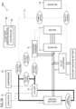
- FIG. 5 is a configuration schematic diagram of a cooling system 200 according to a second embodiment.
- the cooling system 200 according to the embodiment has a configuration similar to that of the cooling system 100 except that a configuration of valves and pumps disposed in the cooling water flow passage 11 and a flow rate control function of a controller 31 included in a flow rate control device 30 are different from those of the cooling system 100 according to the first embodiment described above.
- the configurations similar to those of the cooling system 100 have similar reference numerals as the reference numerals illustrated in FIG. 1 , and for descriptions for the configurations similar to those of the cooling system 100, the descriptions described above are employed as necessary.
- the cooling water flow passage 11 is provided with a pump B, a pump C, and a valve C to a valve G.
- the pump B, the pump C, and the valve C to the valve G are electrically connected to the flow rate control device 30.
- the pump B and the pump C operate or stop corresponding to control signals from the controller 31, and the valve C to the valve G open and close corresponding to control signals from the controller 31.
- the pump B is a water pump for transmitting a cooling water to the cooling water flow passage 11.
- the pump B is disposed at a position corresponding to the valve A in the first embodiment. As soon as the pump B operates by the control signal from the controller 31, the cooling water is transmitted from the pump B to the driving battery 1. On the other hand, as soon as the pump B stops by the control signal from the controller 31, the cooling water is not sent out of the pump B, and thus, no cooling water is transmitted to the driving battery 1.
- the pump C is a water pump corresponding to the pump A illustrated in FIG. 1 , and therefore, the description described above is employed for the description of the pump C.
- the valve D is disposed between the driving battery 1 and the pump C in the cooling water flow passage 11. As soon as the valve D opens by the control signal from the controller 31, the cooling water is transmitted to the pump C. On the other hand, as soon as the valve D closes by the control signal from the controller 31, no cooling water is transmitted to the pump C.
- the valve E is disposed between the on board charger 6 and the chiller 12 in the cooling water flow passage 11. As soon as the valve E opens by the control signal from the controller 31, the cooling water is transmitted to the chiller 12 and the valve F. On the other hand, as soon as the valve E closes by the control signal from the controller 31, no cooling water is transmitted to the chiller 12 or the valve F.
- the valve F is disposed in a branch passage branching between the valve E and the chiller 12 in the cooling water flow passage 11.
- the branch passage where the valve F is disposed is a cooling-down flow passage that branches from the main stream between valve E and the chiller 12, and joins to the main stream between the driving battery 1 and the valve D.
- the controller 31 controls operations of the pump B and the pump C, and controls opening and closing of the valve C to the valve G.
- the controller 31 controls the operations of the pump B and the pump C and controls opening and closing of the valve C to the valve G, and thus, reduces the flow rate of the cooling water to the driving battery 1 compared with the case where the temperature of the driving battery 1 is lower than the temperature of the cooling water when the temperature of the driving battery 1 is higher than the temperature of the cooling water to be transmitted to the driving battery 1 while the ripple charging and discharging is executed.
- the flow rate control function achieved by the controller 21 according to the first embodiment can be achieved by the controller 31 by controlling the operations of the pump B and the pump C and controlling opening and closing of the valve C to the valve G.
- the controller 31 controls the flow rate of the cooling water that exchanges heat with the on board charger 6 corresponding to a charging method of the power feeding facility.
- the driving battery 1 is charged by the rapid charging method, the driving battery 1 is charged from the power feeding facility with the on board charger 6 being stopped.
- the controller 31 controls the operations of the pump B and the pump C, and controls opening and closing of the valve C to the valve G such that the on board charger 6 and the cooling water do not exchange heat when the driving battery 1 is charged from the power feeding facility by the rapid charging method.
- the driving battery 1 is charged by the normal charging method
- the driving battery 1 is charged from the power feeding facility with the on board charger 6 operating.
- the controller 31 controls the operations of the pump B and the pump C, and controls opening and closing of the valve C to the valve G such that the on board charger 6 and the cooling water exchange heat when the driving battery 1 is charged from the power feeding facility by the normal charging method.
- the controller 31 when the temperature of the driving battery 1 is higher than the temperature of the cooling water before heat exchange with the driving battery 1 while the ripple charging and discharging is executed, the controller 31 outputs the control signals for stopping the pump B and the pump C to the pump B and the pump C, and outputs the control signals for closing the valve D to the valve G to the valve D to the valve G.
- FIG. 7A is a drawing illustrating a state where the cooling water flows in the driving battery 1 in a situation where the driving battery 1 is charged in the normal charging method in the cooling system 200 illustrated in FIG. 5 .
- the cooling water sent out of the pump C is, after being cooled down by the radiator 15, transmitted to the inverter 3, the motor 2, the on board charger 6, and the pump B.
- the cooling water sent out of the pump B is transmitted to the driving battery 1 and the pump C.
- the cooling water is transmitted to the driving battery 1, and the cooling water flows in the driving battery 1.
- the controller 31 when the temperature of the driving battery 1 is lower than the temperature of the cooling water before heat exchange with the driving battery 1 while the ripple charging and discharging is executed, the controller 31 outputs the control signal for operating the pump B to the pump B, and outputs the control signal for stopping the pump C to the pump C.
- the controller 31 outputs the control signals for closing the valve D, the valve E, and the valve G to the valve D, the valve E, and the valve G, and outputs the control signal for opening the valve F to the valve F.
- the electric vehicle includes the on board charger 6 for charging the driving battery 1 from outside of the electric vehicle by the normal charging method.
- the cooling water flow passage 11 is a flow passage through which the cooling water that exchanges heat with the driving battery 1, the cooling water that exchanges heat with the inverter 3, the cooling water that exchanges heat with the motor 2, and the cooling water that exchanges heat with the on board charger 6 are allowed to circulate.
- the controller 31 controls the operations of the pump B and the pump C, and controls opening and closing of the valve C to the valve G such that the on board charger 6 and the cooling water do not exchange heat, when the driving battery 1 is charged from outside of the electric vehicle by the rapid charging method.
- the on board charger 6 Since the on board charger 6 is not operated with charging by the rapid charging method, heat exchange with the on board charger 6 that does not generate heat or is less likely to generate heat is prevented, and the heat dissipation amount from the motor 2 and the inverter 3 to the cooling water can be increased. As the result, compared with the case where the cooling water flows in the on board charger 6, cooling down of the motor 2 and the inverter 3 can be accelerated.
- the controller 31 controls the operations of the pump B and the pump C, and controls opening and closing of the valve C to the valve G such that the on board charger 6 and the cooling water exchange heat when the driving battery 1 is charged from outside of the electric vehicle by the normal charging method. Even when the on board charger 6 generates heat due to charging by the normal charging method, the on board charger 6 can be cooled down.
- a modification of the controller 31 will be described in the case where the driving battery 1 is charged by a rapid charging method.
- the controller 31 when charging of the driving battery 1 from outside of the electric vehicle by the rapid charging method is started, outputs a control signal for stopping the charging of the driving battery 1 to a power feeding facility via a predetermined communication line after a predetermined period has passed. After the charging of the driving battery 1 by the rapid charging method is stopped, the controller 31 generates a control signal for ripple charging and discharging and outputs it to the inverter 3.
- the controller 31 stops outputting the control signal for ripple charging and discharging, and outputs a control signal for resuming the charging of the driving battery 1 by the rapid charging method to the power feeding facility.
- the controller 31 controls the control by the controller 31 according to the modification, in the driving battery 1, after the rapid charging is performed, the ripple charging and discharging is performed, and then, the rapid charging is resumed. Since the driving battery 1 generates heat by the rapid charging and the ripple charging and discharging, the heat generation amount can be increased compared with the case where only the rapid charging is performed without the ripple charging and discharging interposed between the rapid charging. As the result, more efficient warming-up of the driving battery 1 is achievable.
- the flow rate control method, the flow rate control device, and the cooling system according to the present invention are also applicable to other electric-powered vehicles.
- the electric-powered vehicle may be what is called a series hybrid vehicle on which an engine as an electric generator, a motor for electric generation, and a motor that generates a driving force that drives the electric-powered vehicle by an electric power from an electric generator or a driving battery are mounted.
- the electric-powered vehicle may be what is called a series parallel vehicle.
- the heating medium is only necessary to be a fluid coolant, and may, for example, be a coolant gas.
- the cooling system according to the present invention has a coolant gas flow passage as a passage for the coolant gas, instead of the cooling water flow passage.
- the coolant gas can also obtain an effect equal to the case with the cooling water.
- the heating medium according to the present invention includes the cooling water or the coolant gas.
- the cooling water flowing in the driving battery is only necessary to be less than the case where the temperature of the driving battery 1 is lower than the temperature of the cooling water before heat exchange with the driving battery 1.
- the controller 21 may output the control signal that can adjust a movable mechanism (valve element) configuring the valve A to the valve A. This allows obtaining an effect equal to the effects in the above-described embodiments.
- the controller 21 may generate the control signal for ripple charging and discharging based on a conventionally known method, that is, the comparison between the same carrier waves with no phase differences and the alternating-current voltage command value.
- the parking lock mechanism may be a parking brake mechanism or a foot braking mechanism, which is conventionally known, or a plurality of these mechanisms may be used in combination.
Landscapes
- Engineering & Computer Science (AREA)
- Power Engineering (AREA)
- Transportation (AREA)
- Mechanical Engineering (AREA)
- Life Sciences & Earth Sciences (AREA)
- Sustainable Development (AREA)
- Sustainable Energy (AREA)
- Electric Propulsion And Braking For Vehicles (AREA)
Abstract
Description
- The present invention relates to a flow rate control method, a flow rate control device, and a cooling system for controlling a flow rate of a heating medium.
- The present application claims priority based on
Japanese Patent Application No. 2021-205477 filed on December 17, 2021 - There has conventionally known a battery system that is mounted on a vehicle and warms up a battery that is to be charged and discharged (Patent Document 1). This battery system includes a battery pack, charge/discharge means, heat exchanging means, transfer means, and a control device. The battery pack is configured by energizably connecting a plurality of battery cells. The charge/discharge means is connected to the battery pack in a wired manner, and executes ripple charging and discharging that alternately charges and discharges for multiple times in one second with the battery pack. The heat exchanging means is provided such that the heat generated from the charge/discharge means and a heat transfer medium exchange heat. The transfer means transfers the heat transfer medium toward the battery pack. The control device controls respective operations of the charge/discharge means and the transfer means. When the battery pack has been determined to be not allowed to produce a required output power because of its low temperature, the control device controls the operation of the charge/discharge means such that the ripple charging and discharging is executed, and further controls the operation of the transfer means such that the heat transfer medium, which receives the heat generated from the charge/discharge means, is transferred to the battery pack.
- Patent Document 1:
Japanese Unexamined Patent Application Publication No. 2010-257722 - The prior art has a problem that efficient temperature rise in a battery is difficult because the heat generated in the battery is emitted outside by heat exchange between the battery and the heat transfer medium while ripple charging and discharging is executed.
- The present invention aims to achieve an object to provide a flow rate control method, a flow rate control device, and a cooling system that allow efficiently raising a temperature of a battery by ripple charging and discharging.
- The present invention, in a vehicle on which a motor that drives the vehicle, a battery that allows supplying an electric power to the motor, and a power conversion device disposed between the motor and the battery are mounted, outputs an execution command of ripple charging and discharging that alternately charges and discharges for multiple times with the battery to the power conversion device when a temperature of the battery is lower than a predetermined threshold temperature, and controls the flow rate of the heating medium such that the flow rate of the heating medium is reduced compared with a case where the temperature of the battery is lower than the temperature of the heating medium when the temperature of the battery is higher than the temperature of the heating medium that exchanges heat with the battery while the ripple charging and discharging is executed, which solves the above-described problem.
- The present invention allows efficiently raising the temperature of the battery by ripple charging and discharging.
-
-
FIG. 1 is a configuration schematic diagram of a cooling system according to a first embodiment. -
FIG. 2 is an exemplary timing chart for describing a flow rate control method of a cooling water. -
FIG. 3A is a drawing illustrating a state where the cooling water does not flow to a driving battery in the cooling system illustrated inFIG. 1 . -
FIG. 3B is a drawing illustrating a state where the cooling water flows to the driving battery in the cooling system illustrated inFIG. 1 . -
FIG. 4 is an exemplary flowchart illustrating a flow rate control method of the cooling water according to the first embodiment. -
FIG. 5 is a configuration schematic diagram of a cooling system according to a second embodiment. -
FIG. 6A is a drawing illustrating a state where the cooling water does not flow to the driving battery in a situation where the driving battery is charged by a normal charging method in the cooling system illustrated inFIG. 5 . -
FIG. 6B is a drawing illustrating a state where the cooling water does not flow to the driving battery in a situation where the driving battery is not charged from a power feeding facility in the cooling system illustrated inFIG. 5 . -
FIG. 7A is a drawing illustrating a state where the cooling water flows to the driving battery in a situation where the driving battery is charged by a normal charging method in the cooling system illustrated inFIG. 5 . -
FIG. 7B is a drawing illustrating a state where the cooling water flows to the driving battery in a situation where the driving battery is not charged from the power feeding facility in the cooling system illustrated inFIG. 5 . - The following describes embodiments of a flow rate control method and a flow rate control device according to the present invention based on the drawings.
-
FIG. 1 is a configuration schematic diagram of acooling system 100 according to a first embodiment. Thecooling system 100 according to the embodiment is a system that is mounted on an electric-powered vehicle, and is for cooling a drivingbattery 1, amotor 2, aninverter 3, and an onboard charger 6, which are described later. In the embodiment, the description is made by using what is called an electric vehicle (EV) that does not include an internal combustion engine, such as a gasoline engine or a diesel engine, but includes thedriving battery 1, theinverter 3 that converts an electric power of the drivingbattery 1, and themotor 2 that generates a driving power that drives the electric-powered vehicle by the electric power output from theinverter 3 as an example for the electric-powered vehicle. - As illustrated in
FIG. 1 , thecooling system 100 includes thedriving battery 1, themotor 2, theinverter 3, a DC-DC converter 4, anauxiliary machine battery 5, and the onboard charger 6 electrically connected by a wiring harness or a busbar. Specifically, theinverter 3 is disposed between thedriving battery 1 and themotor 2, and the DC-DC converter 4 and the onboard charger 6 are connected to a wiring harness that connects between the drivingbattery 1 and theinverter 3. Theauxiliary machine battery 5 is connected to the DC-DC converter 4. Thecooling system 100 includes a flowrate control device 20 that includes acontroller 21. The flowrate control device 20 will be described later. - The
cooling system 100 is provided with a coolingwater flow passage 11 as a passage for cooling water. In the embodiment, the cooling water is described as an example of a heating medium that exchanges heat among thedriving battery 1, theinverter 3, themotor 2, and the onboard charger 6. As illustrated inFIG. 1 , the coolingwater flow passage 11 is provided with achiller 12, aradiator 15, a valve A to valve C, and a pump A. So as to be able to cool thedriving battery 1, theinverter 3, themotor 2, and the onboard charger 6 as cooling targets, the coolingwater flow passage 11 is provided near the respective configurations. In the embodiment, the positioning method or the installation method of the coolingwater flow passage 11 is not specifically limited, but the coolingwater flow passage 11 is provided for the cooling targets by an installation method or a positioning method known as of the filing of the present application. The coolingwater flow passage 11 is configured such that the cooling water is allowed to circulate by open/close control of a valve by the flowrate control device 20 described later. - Next, of the configurations included in the
cooling system 100, a configuration electrically connected by a wiring harness or a busbar will be described. - The driving
battery 1 is configured to be able to supply an electric power to themotor 2 that is a traveling driving source of the electric vehicle. For the drivingbattery 1, for example, a battery pack configured of a nickel-metal hydride secondary battery, a lithium secondary battery, or the like is used. The battery pack is a collective body of a plurality of battery cells connected in series, and has a predetermined internal resistance. To the drivingbattery 1, a ripple current is input from theinverter 3. The ripple current is a current having a charge and discharge pattern alternately repeating charging and discharging in a pulse shape. Once the ripple current is input to thedriving battery 1, charging and discharging corresponding to the ripple current is alternately repeated, and the current by the charging and discharging flows to an internal resistance. This causes the internal resistance to heat up to generate heat inside thedriving battery 1. The drivingbattery 1 is disposed with a temperature sensor (not illustrated) for detecting a temperature of thedriving battery 1. The temperature of the drivingbattery 1 detected by the temperature sensor is output to the flowrate control device 20. The drivingbattery 1 corresponds to an exemplary battery of the present invention. - The
motor 2 is a driving motor that generates a torque for driving driving wheels of the electric vehicle. Themotor 2 generates a driving power by an AC power supplied from theinverter 3, and the generated driving power is transferred to the driving wheels via a reduction gear, which is not illustrated. When the electric vehicle is decelerated, during coast driving, or in a similar situation, themotor 2 rotates as a regenerative driving power is transmitted to themotor 2 from the driving wheels. The rotation of themotor 2 outputs an AC power from themotor 2 to theinverter 3. For themotor 2, for example, a three-phase AC motor is used. Themotor 2 corresponds to an exemplary motor of the present invention. - The
inverter 3 is a power conversion device that converts a DC power input from the drivingbattery 1 into an AC power, and outputs the converted AC power to themotor 2. As described above, when an AC power is output from themotor 2 to theinverter 3, theinverter 3 also functions as a power conversion device that converts an AC power from themotor 2 into a DC power, and outputs the converted DC power to the drivingbattery 1. Theinverter 3 is electrically connected to the flowrate control device 20, and operates corresponding to a control signal from thecontroller 21. - When the
motor 2 is configured of a three-phase AC motor, theinverter 3 is configured of circuits connected to switching elements, such as IGBTs, in a bridged manner, and the circuits allow two-phase to three-phase conversion. Theinverter 3 is configured of three pairs of series circuits (also referred to as three pairs of arm circuits) to which two switching elements are connected in series. The three pairs of series circuits are connected to the drivingbattery 1 in parallel. In theinverter 3, respective connection points between switching elements of upper arms and switching elements of lower arms are connected to output terminals of respective phases (U-phase, V-phase, and W-phase) on themotor 2 side. Theinverter 3 has a smoothing capacitor (not illustrated). The smoothing capacitor is a capacitor for making an input/output voltage of the drivingbattery 1 smooth. The smoothing capacitor is connected between the three pairs of series circuits and the connecting terminals of the drivingbattery 1. Note that an electric circuit, such as a gate driver, that converts the control signal from thecontroller 21 into a control signal for the switching elements by raising the voltage to an operating voltage of the switching elements that configure theinverter 3 may be provided between thecontroller 21 and theinverter 3. Theinverter 3 corresponds to an exemplary power conversion device of the present invention. - The DC-
DC converter 4 decreases the voltage of the drivingbattery 1, and outputs the decreased voltage to theauxiliary machine battery 5. Theauxiliary machine battery 5 is a battery for supplying an electric power to each auxiliary machine (each load) mounted on the electric vehicle. Theauxiliary machine battery 5 is charged by an electric power from the DC-DC converter 4. - The on board charger 6 (OBC) is a device that operates when the driving
battery 1 is charged by a power feeding facility disposed outside the electric vehicle. Conventionally, for the power feeding facility, there have been known a power feeding facility configured to correspond to a normal charging method and a power feeding facility configured to correspond to a rapid charging method. The normal charging method is a method of charging the drivingbattery 1 using a power source of a single-phase alternate current of 100 V or 200 V. The rapid charging method is a method of charging the drivingbattery 1 using a power source of three phase of 200 V. The rapid charging method is able to charge to a full charge in a short time compared with the normal charging method. The onboard charger 6 is used to charge the drivingbattery 1 by the normal charging method. The onboard charger 6 is electrically connected to a charging port of the electric vehicle. A charging cable of the power feeding facility is connected to the charging port of the electric vehicle, and once the electric power from the power feeding facility is supplied, the AC power from the power feeding facility is input to the onboard charger 6. The onboard charger 6 converts the input AC power to a DC power, and outputs the converted DC power to the drivingbattery 1. The onboard charger 6 corresponds to an exemplary on board charger of the present invention. - Next, of the configurations included in the
cooling system 100, the configuration that is disposed inside the coolingwater flow passage 11 or in the vicinity thereof, and is for cooling down the drivingbattery 1, themotor 2, theinverter 3, and the onboard charger 6 described above will be described. - As illustrated in
FIG. 1 , thechiller 12, acompressor 13, and acapacitor 14 configure a cooling circuit driven by, for example, theauxiliary machine battery 5. The cooling circuit has a cooling gas flow passage that allows a cooling gas to circulate as illustrated inFIG. 1 . Thecompressor 13 compresses the cooling gas and discharges the compressed cooling gas having a high temperature and a high pressure. Thecapacitor 14 exchanges heat between the compressed cooling gas and the cooling gas flowing in the cooling gas flow passage, emits the heat of the compressed cooling gas, thus cooling down the compressed cooling gas. - The
chiller 12 is a device for cooling down the cooling water before the heat exchange is performed with the drivingbattery 1. Thechiller 12 is disposed between the onboard charger 6 and the drivingbattery 1 in the coolingwater flow passage 11. Thechiller 12 exchanges heat between the cooling gas flowing in the cooling gas flow passage and the cooling water flowing in the coolingwater flow passage 11, absorbs the heat of the cooling water flowing in the coolingwater flow passage 11, thus cooling down the cooling water. A control signal is input to thechiller 12 from thecontroller 21, and thechiller 12 operates or stops corresponding to the control signal. When thechiller 12 operates, the cooling water flowed from the onboard charger 6 side is cooled down as described above. On the other hand, when thechiller 12 stops, the cooling water flowed from the onboard charger 6 side is not cooled down. - The valve A is disposed between the
chiller 12 and the drivingbattery 1 in the coolingwater flow passage 11. The valve A is electrically connected to the flowrate control device 20, and opens and closes corresponding to the control signal from thecontroller 21. When the valve A opens in accordance with the control signal from thecontroller 21, the cooling water that has passed thechiller 12 is transmitted to the drivingbattery 1. On the other hand, when the valve A closes in accordance with the control signal from thecontroller 21, the cooling water is not transmitted to the drivingbattery 1. - The valve B is disposed in a branch passage branching between the on
board charger 6 and thechiller 12 in the coolingwater flow passage 11. When the coolingwater flow passage 11 through which the cooling water flows in the order from the drivingbattery 1, theinverter 3, themotor 2, and the onboard charger 6 is a main stream, the branch passage where the valve B is disposed is the coolingwater flow passage 11 that branches from the main stream between the onboard charger 6 and thechiller 12, and joins to the main stream between the drivingbattery 1 and the pump A. The valve B is a bypassing valve not for transmitting the cooling water to the drivingbattery 1 but for transmitting the cooling water to the other devices. The valve B is electrically connected to the flowrate control device 20, and opens and closes corresponding to the control signal from thecontroller 21. When the valve B opens in accordance with the control signal from thecontroller 21, the cooling water is transmitted to the pump A from the onboard charger 6. On the other hand, when the valve B closes in accordance with the control signal from thecontroller 21, the cooling water from the onboard charger 6 is not transmitted to the pump A. The valve A and the valve B correspond to exemplary valves of the present invention. - The pump A is a water pump for transmitting the cooling water to the cooling
water flow passage 11. The pump A is disposed between the drivingbattery 1 with the valve B and theradiator 15 with the valve C in the coolingwater flow passage 11. The pump A is electrically connected to the flowrate control device 20, and operates or stops corresponding to the control signal from thecontroller 21. When the pump A operates in accordance with the control signal from thecontroller 21, the cooling water sent out of the pump A is transmitted to the valve C after being cooled down by theradiator 15. On the other hand, when the pump A stops in accordance with the control signal from thecontroller 21, the cooling water is not sent out of the pump A, and the cooling water does not flow in the coolingwater flow passage 11. The pump A functions as transfer means for the cooling water in the coolingwater flow passage 11. - The
radiator 15 is a device for cooling down the cooling water before heat exchange is performed between themotor 2 and theinverter 3. Theradiator 15 is disposed between the pump A and themotor 2 with theinverter 3 in the coolingwater flow passage 11. In the embodiment, theradiator 15 is operated by a predetermined control device, and the cooling water transmitted from the pump A is cooled down by theradiator 15. - The valve C has a function of controlling a water flow rate of the radiator output side. Specifically, the valve C controls the water flow rate of the
radiator 15 so as not to let the water that has passed through the radiator perform cooling until the temperature of the water of themotor 2 and theinverter 3 increases to a predetermined water temperature. That is, the valve C has a function equal to that of a thermostat of an engine radiator. Therefore, the valve C controls a water quantity of theradiator 15 with a water temperature at an inlet of theinverter 3 or at an outlet of the valve C being a target value (for example, stops only the water of the radiator or reduces the water quantity). For example, when the water temperature at the inlet of theinverter 3 is 40°C or more, the valve C opens to cause the water of theradiator 15 to flow. When the water temperature at the inlet of theinverter 3 is less than 40°C, the water of theradiator 15 is stopped (passing water to theradiator 15 is stopped) to decrease the water temperature drop at the inlet of theinverter 3. - Next, the flow
rate control device 20 will be described. The flowrate control device 20 includes thecontroller 21 allowing to achieve the flow rate control method of the present invention. Thecontroller 21 is configured as an electronic control unit made of a computer including hardware and software. The computer of thecontroller 21 is configured of a ROM (Read Only Memory) for executing warming-up control, cooling-down control, and flow rate control, a CPU (Central Processing Unit) executing programs stored in this ROM, and a RAM (Random Access Memory) functioning as an accessible storage device. Note that, for the operation circuit, MPU (Micro Processing Unit), DSP (Digital Signal Processor), ASIC (Application Specific Integrated Circuit), FPGA (Field Programmable Gate Array), and the like may be used instead of the CPU or together with the CPU. The flowrate control device 20 corresponds to an exemplary flow rate control device of the present invention. - A warming-up function achieved by the
controller 21 will be described. Thecontroller 21 controls theinverter 3 such that the ripple charging and discharging that repeats charging and discharging for multiple times in the drivingbattery 1 is executed by the warming-up function when a warming-up request is input. The warming-up request is a signal for raising the temperature of the drivingbattery 1 by ripple charging and discharging. The warming-up request is input to thecontroller 21 at least when the temperature of the drivingbattery 1 is lower than a predetermined warming-up target threshold (unit: temperature). The warming-up target threshold is a temperature determined in advance, and is, for example, 10°C. For example, thecontroller 21 obtains the temperature of the drivingbattery 1 from a temperature sensor detecting the temperature of the drivingbattery 1. Thecontroller 21 compares the temperature of the drivingbattery 1 with the warming-up target threshold, and when the temperature of the drivingbattery 1 is lower than the warming-up target threshold, thecontroller 21 generates a control signal for ripple charging and discharging that turns on or off the switching elements that configure theinverter 3 by pulse-width modulation system. The control signal for ripple charging and discharging is a control signal for flowing a ripple current in a pulse shape alternately repeating charging and discharging at a predetermined cycle to the drivingbattery 1 from theinverter 3. - Here, a method for generating the control signal for ripple charging and discharging according to the embodiment will be described. Conventionally, as a method for generating a control signal to a switching element, there has been known a pulse-width modulation system that generates a gate driving signal for the switching element based on a comparison between a three-phase alternating-current voltage command value and a carrier wave (carrier). In the embodiment, the
controller 21 compares carrier waves having phases corresponding to the respective phases of themotor 2, not the same carrier waves with no phase differences, with the three-phase alternating-current voltage value, and generates control signals for ripple charging and discharging to the switching elements of the respective phases. For example, thecontroller 21 sets a phase difference of 180 degrees between a carrier wave (carrier wave A) as a comparison target of an alternating-current voltage command value of the U-phase and a carrier wave (carrier wave B) as a comparison target of an alternating-current voltage command value of the V-phase and the W-phase. Thecontroller 21, then, generates a control signal for ripple charging and discharging to the switching element of the U-phase based on the comparison between the alternating-current voltage command value of the U-phase and the carrier wave A. Thecontroller 21 also generates a control signal for ripple charging and discharging to the switching element of the V-phase based on the comparison between the alternating-current voltage command value of the V-phase and the carrier wave B, and generates a control signal for ripple charging and discharging to the switching element of the W-phase based on the comparison between the alternating-current voltage command value of the W-phase and the carrier wave B. By generating the control signals for ripple charging and discharging using the carrier wave having the phase corresponding to each of the phases of themotor 2, the ripple current having the same component as that of the frequency (carrier frequency) of the carrier wave is generatable. Compared with the ripple current generated using the same carrier waves with no phase differences, the ripple current having a high frequency component is generatable. As the result, a heat generation amount in the internal resistance can be increased to allow enhancing the temperature increase rate of the drivingbattery 1. Note that the carrier wave A and the carrier wave B having the phase difference of 180 degrees as described above are merely an example, and the phase difference between the carrier waves is not limited to 180 degrees. In order to obtain the above-described effect, it is only necessary that the carrier waves have two or more phases of themotor 2 differing from one another. - The
controller 21 outputs the control signal for ripple charging and discharging to theinverter 3 as an execution command to theinverter 3. This causes theinverter 3 to repeatedly turning on and off the switching elements of the respective phases by the control signal for ripple charging and discharging, and the ripple current flows from theinverter 3 to the drivingbattery 1. - As an example where the warming-up request is input, the case where the temperature of the driving
battery 1 is lower than the warming-up target threshold has been described, but the configuration in which, when the state of the electric vehicle satisfies a predetermined condition in addition to the temperature condition of the drivingbattery 1, the warming-up request is input to thecontroller 21, may be employed. The state of the electric vehicle for performing the ripple charging and discharging includes at least any one of the state of charging the drivingbattery 1 from a power feeding facility provided outside the electric vehicle, the state where the electric vehicle is stopped with the ignition switch turned on, and the state where the ignition switch is turned off and the warming-up switch is turned on. The warming-up switch is a switch that is provided in the vehicle and can be operated by a passenger for warming-up the drivingbattery 1. When the electric vehicle is in any state of these states, and the temperature of the drivingbattery 1 is lower than the warming-up target threshold, the warming-up request is input to thecontroller 21, and thecontroller 21 controls theinverter 3 by warming-up function. - Next, a cooling-down function achieved by the
controller 21 will be described. The cooling-down function is a function for cooling down the drivingbattery 1. When the cooling-down request is input, thecontroller 21 outputs the control signal for operating thechiller 12 to thechiller 12 and cools down the cooling water to be transmitted to the drivingbattery 1 with thechiller 12 by the cooling-down function. The cooling water to be transmitted to the drivingbattery 1 is cooled down, and thus, the heat release to the cooling water from the drivingbattery 1 is accelerated to cool down the drivingbattery 1. The cooling-down request is a signal for operating thechiller 12. The cooling-down request is input to thecontroller 21 at least when the temperature of the drivingbattery 1 is higher than a predetermined cooling-down threshold (unit: temperature). The cooling-down threshold is a temperature higher than the above-described warming-up target threshold. The cooling-down threshold is a temperature determined in advance, and is, for example, 40°C. For example, thecontroller 21 compares the temperature of the drivingbattery 1 with the cooling-down threshold, and when the temperature of the drivingbattery 1 is higher than the cooling-down threshold, the control signal for operating thechiller 12 is output to thechiller 12. - Next, a flow rate control function achieved by the
controller 21 will be described. The flow rate control function is a function for controlling the flow rate of the cooling water flowing in the coolingwater flow passage 11. In the embodiment, when the temperature of the drivingbattery 1 is higher than the temperature of the cooling water to be transmitted to the drivingbattery 1 while the ripple charging and discharging is executed, thecontroller 21 reduces the flow rate of the cooling water to the drivingbattery 1 compared with the case where the temperature of the drivingbattery 1 is lower than the temperature of the cooling water by controlling opening and closing of the valve A and the valve B. The cooling water to be transmitted to the drivingbattery 1 is a cooling water before exchanging heat with the driving battery 1 (hereinafter, also referred to as the cooling water before heat exchange with the driving battery 1). In the example inFIG. 1 , the cooling water before heat exchange with the drivingbattery 1 is a cooling water flowing in the coolingwater flow passage 11 between thechiller 12 and the drivingbattery 1. A water temperature sensor (not illustrated) that detects the temperature of the cooling water is disposed between thechiller 12 and the valve A in the coolingwater flow passage 11. The temperature of the cooling water before heat exchange with the drivingbattery 1 detected by the water temperature sensor is output to the flowrate control device 20. Note that the water temperature sensor may be disposed between the valve A and the drivingbattery 1 in the coolingwater flow passage 11. - The
controller 21 controls opening and closing of the valve A and the valve B such that theinverter 3 and the cooling water exchange heat and themotor 2 and the cooling water exchange heat while the ripple charging and discharging is executed. When the temperature of the drivingbattery 1 is higher than the temperature of the cooling water before heat exchange with the drivingbattery 1 while the ripple charging and discharging is executed, thecontroller 21 controls opening and closing the valve A and the valve B such that any of the flow rates of the flow rate of the cooling water that exchanges heat with theinverter 3 and the flow rate of the cooling water that exchanges heat with themotor 2 is increased more than the flow rate of the cooling water before heat exchange with the drivingbattery 1. In the case of the configuration of the cooling water flow passage in which themotor 2 and theinverter 3 are arranged in series in the coolingwater flow passage 11 as in the embodiment, the flow rate of the cooling water that exchanges heat with themotor 2 and the flow rate of the cooling water that exchanges heat with theinverter 3 each fail to be independently controlled, and therefore, the flow rate of the cooling water that exchanges heat with themotor 2 and the flow rate of the cooling water that exchanges heat with theinverter 3 are substantially equal. In view of this, the target that is increased more than the flow rate of the cooling water before heat exchange with the drivingbattery 1 by thecontroller 21 is any of the flow rates of the flow rate of the cooling water that exchanges heat with theinverter 3 and the flow rate of the cooling water that exchanges heat with themotor 2. On the other hand, unlike the embodiment, in the case of the configuration of the cooling water flow passage in which themotor 2 and theinverter 3 are arranged in parallel in the coolingwater flow passage 11, the flow rate of the cooling water that exchanges heat with themotor 2 and the flow rate of the cooling water that exchanges heat with theinverter 3 are controllable in a manner independent of one another. In view of this, when themotor 2 and theinverter 3 are arranged in parallel in the coolingwater flow passage 11, and the temperature of the drivingbattery 1 is higher than the temperature of the cooling water before heat exchange with the drivingbattery 1 while the ripple charging and discharging is executed, thecontroller 21 controls opening and closing of the valve A and the valve B such that a sum of the flow rate of the cooling water that exchanges heat with theinverter 3 and the flow rate of the cooling water that exchanges heat with themotor 2 is increased more than the flow rate of the cooling water before heat exchange with the drivingbattery 1. When the temperature of the drivingbattery 1 is lower than the temperature of the cooling water before heat exchange with the drivingbattery 1 while the ripple charging and discharging is executed, thecontroller 21 controls opening and closing of the valve A and the valve B such that the cooling water that has received the heat generated by theinverter 3 and the cooling water that has received the heat generated from themotor 2 exchange heat with the drivingbattery 1. When the temperature of the drivingbattery 1 is lower than the temperature of the cooling water before heat exchange with the drivingbattery 1 while the ripple charging and discharging is executed, thecontroller 21 controls opening and closing of the valve A and the valve B such that the cooling water is circulated to exchange heat with each of the devices. - With reference to
FIG. 2 andFIG. 3 , a flow rate control method of the cooling water will be described.FIG. 2 is an exemplary timing chart for describing the flow rate control method of the cooling water. -
FIG. 2 illustrates each of states of temperatures (the temperature of the drivingbattery 1, the temperature of the cooling water before heat exchange with the driving battery 1), an open/close state of the valve A, an open/close state of valve B, an operation state of the pump A, an input/output current of the drivingbattery 1, a cooling water amount of the drivingbattery 1, a cooling water amount of themotor 2 and theinverter 3, a vehicle speed of the electric vehicle, and a parking lock of the electric vehicle from the top. InFIG. 2 , the horizontal axes indicate time. - At Time t0, the electric vehicle is stopped by parking lock mechanism. The parking lock mechanism is a mechanism for locking a gear in a gear box, and is a mechanism that makes an axle shaft as an output shaft unrotatable. The gear box is provided on the axle shaft connecting right and left driving wheels. Once the parking lock is turned on, gear teeth of the gear engage with the parking lock and the gear is locked, and thus, the rotation of the driving wheels is restrained. On the other hand, once the parking lock is turned off, the gear released from being locked is rotatable, and the driving force from the
motor 2 rotates the driving wheels. - As illustrated in
FIG. 2 , at Time t0, the temperature of the drivingbattery 1 is lower than the warming-up target threshold. Since it is in the state where the temperature of the drivingbattery 1 is lower than the warming-up target threshold and the vehicle is stopped, the warming-up request is input to thecontroller 21, and thecontroller 21 outputs the control signal for ripple charging and discharging to theinverter 3. Time t0 is the time at which the ripple charging and discharging is started in the drivingbattery 1. - At Time t0, the
controller 21 outputs the control signal for operating the pump A to the pump A and sends out the cooling water to the coolingwater flow passage 11. Thecontroller 21 outputs the control signal for closing the valve A to the valve A and outputs the control signal for opening the valve B to the valve B. -
FIG. 3A is a drawing illustrating a state where the cooling water does not flow to the drivingbattery 1 in thecooling system 100 illustrated inFIG. 1 . When the valve A is closed and the valve B is opened, as illustrated inFIG. 3A , after being cooled down by theradiator 15, the cooling water sent out of the pump A circulates the coolingwater flow passage 11 in the order from theinverter 3, themotor 2, the onboard charger 6, and the pump A. Meanwhile, since the valve A is closed, the cooling water is not transmitted to the drivingbattery 1, thus, no cooling water flows in the drivingbattery 1. - Referring again to
FIG. 2 , after Time t0, thecontroller 21 obtains the temperature of the drivingbattery 1 from the temperature sensor that detects the temperature of the drivingbattery 1 and obtains the temperature of the cooling water before heat exchange with the drivingbattery 1 from the water temperature sensor disposed between thechiller 12 and the valve A. - From Time to to Time t1, the driving
battery 1 has heat generated inside thereof by the ripple charging and discharging, and the temperature of the drivingbattery 1 is increased. That is, the warming-up control of the drivingbattery 1 by the ripple charging and discharging is executed. In theinverter 3, the switching element is repeatedly turned on and off for ripple charging and discharging, and therefore, theinverter 3 generates heat. The current caused by the ripple current flows in themotor 2, and themotor 2 generates heat. The cooling water before exchanging heat with the drivingbattery 1 is warmed by the heat generated by theinverter 3 and themotor 2, and thus, the temperature of the cooling water before heat exchange with the drivingbattery 1 is also increased. From Time to to Time t1, since the temperature of the drivingbattery 1 is higher than the temperature of the cooling water before heat exchange with the drivingbattery 1, thecontroller 21 outputs the control signal for closing the valve A to the valve A and outputs the control signal for opening the valve B to the valve B. From Time to to Time t1, as illustrated inFIG. 3 (A) , the cooling water does not flow in the drivingbattery 1. - At Time t1, the temperature of the cooling water before heat exchange with the driving
battery 1 is higher than the temperature of the drivingbattery 1. Thecontroller 21 outputs the control signal for opening the valve A to the valve A and outputs the control signal for closing the valve B to the valve B. -
FIG. 3B is a drawing illustrating a state where the cooling water flows in the drivingbattery 1 in thecooling system 100 illustrated inFIG. 1 . When the valve A is opened and the valve B is closed, as illustrated inFIG. 3B , after being cooled down by theradiator 15, the cooling water sent out of the pump A circulates in the coolingwater flow passage 11 in the order from theinverter 3, themotor 2, the onboard charger 6, the drivingbattery 1, and the pump A. Since the valve A is opened, the cooling water is transmitted to the drivingbattery 1, thus, the cooling water flows in the drivingbattery 1. - Referring again to
FIG. 2 , from Time t1 to Time t2, since the temperature of the drivingbattery 1 is lower than the temperature of the cooling water before heat exchange with the drivingbattery 1, thecontroller 21 outputs the control signal for opening the valve A to the valve A and outputs the control signal for closing the valve B to the valve B. From Time t1 to Time t2, as illustrated inFIG. 3B , the cooling water flows in the drivingbattery 1. - At Time t2, the temperature of the driving
battery 1 is higher than the temperature of the cooling water before heat exchange with the drivingbattery 1. Thecontroller 21 outputs the control signal for closing the valve A to the valve A and outputs the control signal for opening the valve B to the valve B. In view of this, as illustrated inFIG. 3 (A) , again, the cooling water is not transmitted to the drivingbattery 1, and therefore, no cooling water flows in the drivingbattery 1. - From Time t2 to Time t3, since the temperature of the driving
battery 1 is higher than the temperature of the cooling water before heat exchange with the drivingbattery 1, thecontroller 21 outputs the control signal for closing the valve A to the valve A and outputs the control signal for opening the valve B to the valve B. From Time t2 to Time t3, as illustrated inFIG. 3A , no cooling water flows in the drivingbattery 1. - As the result of the temperature rise of the driving
battery 1 by ripple charging and discharging from Time t0, the temperature of the driving battery reaches the warming-up target threshold at Time t3. Thecontroller 21 stops outputting the control signal for ripple charging and discharging to theinverter 3 as a stop command of the ripple charging and discharging. Thecontroller 21 outputs the control signal for stopping the pump A to the pump A. The stop of the pump A causes no cooling water to flow in the drivingbattery 1, themotor 2, or theinverter 3. The reason of no cooling water flowing in the coolingwater flow passage 11 is based on the aspect that there is no cause of heat generation in the drivingbattery 1, themotor 2, or theinverter 3 as there is no necessity of the ripple charging and discharging and the electric vehicle is stopped. - At Time t4, as soon as the parking lock is turned off, the electric vehicle starts to travel. The
controller 21 outputs the control signal for operating the pump A to the pump A. Thecontroller 21 outputs the control signal for opening the valve A to the valve A and outputs the control signal for closing the valve B to the valve B. In view of this, as illustrated inFIG. 3B , in thecooling system 100, after being cooled down by theradiator 15, the cooling water sent out of the pump A circulates in the coolingwater flow passage 11 in the order from theinverter 3, themotor 2, the onboard charger 6, the drivingbattery 1, and the pump A. The drivingbattery 1, themotor 2, and theinverter 3 that generate heat in association with the traveling of the electric vehicle can be cooled down. - As the result of the temperature rise of the driving
battery 1 in association with the traveling of the electric vehicle, at Time t5, the temperature of the driving battery reaches the cooling-down threshold. The cooling-down request is input to thecontroller 21, and thecontroller 21 outputs the control signal for operating thechiller 12 to thechiller 12. This cools down the cooling water before heat exchange with the drivingbattery 1 and accelerates the cooling down of the drivingbattery 1. Note that the parking lock is turned on and the electric vehicle is again stopped at Time t5. -
FIG. 4 is an exemplary flowchart illustrating the flow rate control method of the cooling water according to the embodiment. The flowchart illustrated inFIG. 4 is executed at each predetermined cycle by thecontroller 21. - At step S1, the
controller 21 determines whether there is a cooling-down request of the drivingbattery 1 or not. The cooling-down request of the drivingbattery 1 is input to thecontroller 21 at least when the temperature of the drivingbattery 1 is higher than the predetermined cooling-down threshold. When the cooling-down request is input to thecontroller 21, the procedure proceeds to Step S8, and when the cooling-down request is not input to thecontroller 21, the procedure proceeds to Step S2. - At Step S2, the
controller 21 determines whether the electric vehicle is stopped or not. For example, thecontroller 21 obtains a signal indicating the operation state of the parking lock mechanism from another control device that controls the operation of the parking lock mechanism to determine whether the parking lock is turned on or off. When it is determined that the parking lock is turned on and the vehicle is stopped, the procedure proceeds to Step S3, and when it is determined that the parking lock is turned off and the vehicle is not stopped, the procedure proceeds to Step S9. - At Step S3, the
controller 21 compares the temperature of the drivingbattery 1 with the warming-up target threshold, and determines whether the temperature of the drivingbattery 1 is lower than the warming-up target threshold or not. The timing at which the temperature of the drivingbattery 1 is obtained from the temperature sensor is not limited, thecontroller 21 may obtain the temperature of the drivingbattery 1 from the temperature sensor at Step S3 or may obtain the temperature of the drivingbattery 1 from the temperature sensor before Step S3. When an affirmative determination is made by thecontroller 21, the procedure proceeds to Step S4, and when a negative determination is made by thecontroller 21, the procedure proceeds to Step S9. Note that thecontroller 21 may determine whether there is a warming-up request of the drivingbattery 1 or not as a step in whichStep 2 andStep 3 are integrated into one, similarly to Step S1. That is, the flowchart illustrated inFIG. 4 may be a flowchart in which the procedure proceeds to Step 4 when the warming-up request is input to thecontroller 21 and the procedure proceeds to Step S9 when the warming-up request is not input to thecontroller 21. - At Step S4, the
controller 21 outputs the control signal for ripple charging and discharging to theinverter 3 as an execution command of the ripple charging and discharging. In theinverter 3, the switching element is repeatedly turned on and off corresponding to the control signal for ripple charging and discharging, and the ripple current for alternately charging and discharging for multiple times is output from theinverter 3 to the drivingbattery 1. - At Step S5, the
controller 21 obtains the temperature of the cooling water before heat exchange with the drivingbattery 1 from the water temperature sensor. - At Step S6, the
controller 21 compares the temperature of the drivingbattery 1 with the temperature of the cooling water before heat exchange with the drivingbattery 1 obtained at Step S5, and determines whether the temperature of the drivingbattery 1 is higher than the temperature of the cooling water before heat exchange with the drivingbattery 1 or not. When an affirmative determination is made by thecontroller 21, the procedure proceeds to Step S7, and when a negative determination is made by thecontroller 21, the procedure proceeds to Step S9. - At Step S7, the
controller 21 outputs the control signal for closing the valve A to the valve A and outputs the control signal for opening the valve B to the valve B. In view of this, as illustrated inFIG. 3A , closing the valve A causes no cooling water to flow in the drivingbattery 1. On the other hand, opening the valve B causes the cooling water to flow in theinverter 3, themotor 2, and the onboard charger 6. When the process at Step S7 is finished, thecontroller 21 terminates the process of the flowchart illustrated inFIG. 4 . - When a negative determination is made at Step S1, the procedure proceeds to Step S8. At Step S8, the
controller 21 outputs the control signal for operating thechiller 12 to thechiller 12. When the process at Step S8 is finished, the procedure proceeds to Step S9. - When a negative determination is made in any of the steps of Step S2, Step S3, or Step S6, or when the process at Step S8 is finished, the procedure proceeds to Step S9. At Step S9, the
controller 21 outputs the control signal for opening the valve A to the valve A and outputs the control signal for closing the valve B to the valve B. In view of this, as illustrated inFIG. 3 (B) , opening the valve A causes the cooling water to flow in the drivingbattery 1. The cooling water sent out of the pump A circulates in the coolingwater flow passage 11 in the order of theinverter 3, themotor 2, the onboard charger 6, the drivingbattery 1, and the pump A. When the process is finished at Step S9, thecontroller 21 terminates the process of the flowchart illustrated inFIG. 4 . - As described above, in the embodiment, when, in the electric vehicle on which the
motor 2 that drives the electric vehicle, the drivingbattery 1 that is allowed to supply an electric power to themotor 2, and theinverter 3 disposed between themotor 2 and the drivingbattery 1 are mounted, the temperature of the drivingbattery 1 is lower than the predetermined warming-up target threshold, the execution command of ripple charging and discharging that alternately charges and discharges for multiple times with the drivingbattery 1 is output to theinverter 3, and when the temperature of the drivingbattery 1 is higher than the temperature of the cooling water that exchanges heat with the drivingbattery 1 while the ripple charging and discharging is executed, the flow rate of the cooling water is reduced compared with the case where the temperature of the drivingbattery 1 is lower than the temperature of the cooling water. This allows suppressing or reducing that the heat generated in the drivingbattery 1 by the ripple charging and discharging is emitted to the cooling water, and therefore, the temperature of the drivingbattery 1 can be efficiently raised by the ripple charging and discharging. As the result, the temperature rise rate of the drivingbattery 1 is increased, and the inputtable/outputtable electric power of the drivingbattery 1 can be increased promptly from a low temperature state. For example, shortening of the charging time by the rapid charging method may be attempted. For example, the chargeable power of the drivingbattery 1 by regeneration at deceleration is increased, and therefore, improvement in electricity cost performance of the drivingbattery 1 may be attempted. - In the embodiment, the electric vehicle includes the cooling
water flow passage 11, and the valves A, B, and the pump A disposed in the coolingwater flow passage 11. Thecontroller 21 controls opening and closing of the valve A and the valve B, and thus, reduces the flow rate of the cooling water when the temperature of the drivingbattery 1 is higher than the temperature of the cooling water exchanging heat with the drivingbattery 1 while the ripple charging and discharging is executed, compared with the case where the temperature of the drivingbattery 1 is lower than the temperature of the cooling water. The simple method of open/close control of the valves allows efficiently raising the temperature of the drivingbattery 1 by ripple charging and discharging. Since it is achievable by installing the valve A and the valve B in the coolingwater flow passage 11, suppression of enlargement of thecooling system 100 may be achieved. - In the embodiment, the cooling
water flow passage 11 is a flow passage through which the cooling water that exchanges heat with the drivingbattery 1, the cooling water that exchanges heat with theinverter 3, and the cooling water that exchanges heat with themotor 2 are allowed to circulate. Thecontroller 21 controls opening and closing of the valve A and the valve B such that theinverter 3 and the cooling water exchange heat and themotor 2 and the cooling water exchange heat while the ripple charging and discharging is executed. This enables the heat generated in themotor 2 and theinverter 3 by ripple charging and discharging to be emitted in the cooling water thus allowing cooling down themotor 2 and theinverter 3. As the result, the possibility of breakdown of themotor 2 and theinverter 3 caused by heat may be reduced. - In the embodiment, the
controller 21 controls opening and closing of the valve A and the valve B such that any flow rate of the flow rate of the cooling water that exchanges heat with theinverter 3 and the flow rate of the cooling water that exchanges heat with themotor 2 is increased more than the flow rate of the cooling water before heat exchange with the drivingbattery 1 when the temperature of the drivingbattery 1 is higher than the temperature of the cooling water before heat exchange with the drivingbattery 1 while the ripple charging and discharging is executed. This allows suppressing or reducing the emission of the heat generated in the drivingbattery 1 to the cooling water, also allows emitting the heat generated in themotor 2 and theinverter 3 to the cooling water. - In the embodiment, the
controller 21 controls opening and closing of the valve A and the valve B such that the cooling water that has received the heat generated by theinverter 3 and the cooling water that has received the heat generated by themotor 2 exchange heat with the drivingbattery 1 when the temperature of the drivingbattery 1 is lower than the temperature of the cooling water before heat exchange with the drivingbattery 1 while the ripple charging and discharging is executed. This causes the cooling water warmed up by the heat generated by themotor 2 and theinverter 3 to exchange heat with the drivingbattery 1 thereby allowing heating the drivingbattery 1 from outside. In addition to self-heating by ripple charging and discharging, the heating from outside makes more efficient warm-up of the drivingbattery 1 achievable. - In the embodiment, the
controller 21 controls opening and closing of the valve A and the valve B such that the cooling water is circulated and exchanges heat with each of the devices when the temperature of the drivingbattery 1 is lower than the temperature of the cooling water before heat exchange with the drivingbattery 1 while the ripple charging and discharging is executed. The cooling water heated by the heat generated by themotor 2 and theinverter 3 can be transmitted to the drivingbattery 1 in a state where the heat generated by ripple charging and discharging is not emitted to the cooling water. As the result, an effect equal to the above-described effect can be obtained. - In the embodiment, in the state where the electric car is stopped by the parking lock mechanism that makes the output shaft unrotatable, the
controller 21 outputs the execution command of ripple charging and discharging. Even in the state where the rotation of the driving wheels is not stoppable due to the driving force from themotor 2 by ripple charging and discharging, the drivingbattery 1 can be warmed up. -
FIG. 5 is a configuration schematic diagram of acooling system 200 according to a second embodiment. Thecooling system 200 according to the embodiment has a configuration similar to that of thecooling system 100 except that a configuration of valves and pumps disposed in the coolingwater flow passage 11 and a flow rate control function of acontroller 31 included in a flowrate control device 30 are different from those of thecooling system 100 according to the first embodiment described above. In view of this, inFIG. 5 , the configurations similar to those of thecooling system 100 have similar reference numerals as the reference numerals illustrated inFIG. 1 , and for descriptions for the configurations similar to those of thecooling system 100, the descriptions described above are employed as necessary. - As illustrated in
FIG. 5 , the coolingwater flow passage 11 according to the embodiment is provided with a pump B, a pump C, and a valve C to a valve G. Similarly to the first embodiment, the pump B, the pump C, and the valve C to the valve G are electrically connected to the flowrate control device 30. The pump B and the pump C operate or stop corresponding to control signals from thecontroller 31, and the valve C to the valve G open and close corresponding to control signals from thecontroller 31. - The pump B is a water pump for transmitting a cooling water to the cooling
water flow passage 11. The pump B is disposed at a position corresponding to the valve A in the first embodiment. As soon as the pump B operates by the control signal from thecontroller 31, the cooling water is transmitted from the pump B to the drivingbattery 1. On the other hand, as soon as the pump B stops by the control signal from thecontroller 31, the cooling water is not sent out of the pump B, and thus, no cooling water is transmitted to the drivingbattery 1. - The pump C is a water pump corresponding to the pump A illustrated in
FIG. 1 , and therefore, the description described above is employed for the description of the pump C. - The valve D is disposed between the driving
battery 1 and the pump C in the coolingwater flow passage 11. As soon as the valve D opens by the control signal from thecontroller 31, the cooling water is transmitted to the pump C. On the other hand, as soon as the valve D closes by the control signal from thecontroller 31, no cooling water is transmitted to the pump C. - The valve E is disposed between the on
board charger 6 and thechiller 12 in the coolingwater flow passage 11. As soon as the valve E opens by the control signal from thecontroller 31, the cooling water is transmitted to thechiller 12 and the valve F. On the other hand, as soon as the valve E closes by the control signal from thecontroller 31, no cooling water is transmitted to thechiller 12 or the valve F. - The valve F is disposed in a branch passage branching between the valve E and the
chiller 12 in the coolingwater flow passage 11. When the coolingwater flow passage 11 through which the cooling water flows in the order from the drivingbattery 1, theinverter 3, themotor 2, and the onboard charger 6 is a main stream, the branch passage where the valve F is disposed is a cooling-down flow passage that branches from the main stream between valve E and thechiller 12, and joins to the main stream between the drivingbattery 1 and the valve D. - The valve G is disposed in a branch passage branching between the on
board charger 6 and the valve E in the coolingwater flow passage 11. When the coolingwater flow passage 11 described in the description of the valve F is the main stream, the branch passage in which the valve G is disposed is a cooling-down flow passage that branches from the main stream between the onboard charger 6 and the valve E and joins the main stream between the valve D and the pump C. - Next, a flow rate control function achieved by the
controller 31 according to the embodiment will be described. In the embodiment, instead of the open and close control of the valve A and the valve B by thecontroller 21 according to the first embodiment, thecontroller 31 controls operations of the pump B and the pump C, and controls opening and closing of the valve C to the valve G. For example, thecontroller 31 controls the operations of the pump B and the pump C and controls opening and closing of the valve C to the valve G, and thus, reduces the flow rate of the cooling water to the drivingbattery 1 compared with the case where the temperature of the drivingbattery 1 is lower than the temperature of the cooling water when the temperature of the drivingbattery 1 is higher than the temperature of the cooling water to be transmitted to the drivingbattery 1 while the ripple charging and discharging is executed. In other words, the flow rate control function achieved by thecontroller 21 according to the first embodiment can be achieved by thecontroller 31 by controlling the operations of the pump B and the pump C and controlling opening and closing of the valve C to the valve G. - In the embodiment, the
controller 31 controls the flow rate of the cooling water that exchanges heat with the onboard charger 6 corresponding to a charging method of the power feeding facility. When the drivingbattery 1 is charged by the rapid charging method, the drivingbattery 1 is charged from the power feeding facility with the onboard charger 6 being stopped. Thecontroller 31 controls the operations of the pump B and the pump C, and controls opening and closing of the valve C to the valve G such that the onboard charger 6 and the cooling water do not exchange heat when the drivingbattery 1 is charged from the power feeding facility by the rapid charging method. On the other hand, when the drivingbattery 1 is charged by the normal charging method, the drivingbattery 1 is charged from the power feeding facility with the onboard charger 6 operating. Thecontroller 31 controls the operations of the pump B and the pump C, and controls opening and closing of the valve C to the valve G such that the onboard charger 6 and the cooling water exchange heat when the drivingbattery 1 is charged from the power feeding facility by the normal charging method. - Next, with reference to
FIG. 6 andFIG. 7 , a flow rate control method of the cooling water according to the embodiment will be described. -
FIG. 6A is a drawing illustrating a state where the cooling water does not flow in the drivingbattery 1 in a situation where the drivingbattery 1 is charged by the normal charging method in thecooling system 200 illustrated inFIG. 5 . When the pump B is stopped, the pump C is operated, the valve D to the valve F are closed, and the valve G is opened by thecontroller 31, as illustrated inFIG. 6A , the cooling water sent out of the pump C circulates in the coolingwater flow passage 11 in the order from theinverter 3, themotor 2, the onboard charger 6, and the pump C after being cooled down by theradiator 15. On the other hand, stopping the pump B causes no cooling water to be transmitted to the drivingbattery 1, and thus, no cooling water flows in the drivingbattery 1. The cooling water flows in the onboard charger 6 in a state where the onboard charger 6 operates by charging by the normal charging method. -
FIG. 6B is a drawing illustrating a state where the cooling water does not flow in the drivingbattery 1 in a situation where the drivingbattery 1 is not charged from the power feeding facility in thecooling system 200 illustrated inFIG. 5 . As soon as the pump B and the pump C are stopped and the valve D to the valve G are closed by thecontroller 31, as illustrated inFIG. 6B , no cooling water flows in the coolingwater flow passage 11. For example, as in Time to to Time t1 illustrated inFIG. 2 , when the temperature of the drivingbattery 1 is higher than the temperature of the cooling water before heat exchange with the drivingbattery 1 while the ripple charging and discharging is executed, thecontroller 31 outputs the control signals for stopping the pump B and the pump C to the pump B and the pump C, and outputs the control signals for closing the valve D to the valve G to the valve D to the valve G. -
FIG. 7A is a drawing illustrating a state where the cooling water flows in the drivingbattery 1 in a situation where the drivingbattery 1 is charged in the normal charging method in thecooling system 200 illustrated inFIG. 5 . As soon as the pump B and the pump C are operated, and the valve F, and the valve G are closed and the valve D and the valve E are opened by thecontroller 31, as illustrated inFIG. 7A , the cooling water sent out of the pump C is, after being cooled down by theradiator 15, transmitted to theinverter 3, themotor 2, the onboard charger 6, and the pump B. The cooling water sent out of the pump B is transmitted to the drivingbattery 1 and the pump C. By the operation of the pump B, the cooling water is transmitted to the drivingbattery 1, and the cooling water flows in the drivingbattery 1. In the state where the onboard charger 6 is operated by charging by the normal charging method, the cooling water flows in the onboard charger 6. The cooling water circulates in the coolingwater flow passage 11 in the order from theinverter 3, themotor 2, the onboard charger 6, the drivingbattery 1, and theinverter 3. -
FIG. 7B is a drawing illustrating a state where the cooling water flows in the drivingbattery 1 in a situation where the drivingbattery 1 is not charged from the power feeding facility in thecooling system 200 illustrated inFIG. 5 . As soon as the pump B is operated and the pump C is stopped, and the valve D, the valve E, and the valve G are closed and the valve F is opened by thecontroller 31, as illustrated inFIG. 7B , the cooling water sent out of the pump B circulates in the coolingwater flow passage 11 in the order from the drivingbattery 1, the valve F, thechiller 12, and the pump B. For example, as in Time t1 to Time t2 illustrated inFIG. 2 , when the temperature of the drivingbattery 1 is lower than the temperature of the cooling water before heat exchange with the drivingbattery 1 while the ripple charging and discharging is executed, thecontroller 31 outputs the control signal for operating the pump B to the pump B, and outputs the control signal for stopping the pump C to the pump C. Thecontroller 31 outputs the control signals for closing the valve D, the valve E, and the valve G to the valve D, the valve E, and the valve G, and outputs the control signal for opening the valve F to the valve F. - As described above, in the embodiment, the electric vehicle includes the on
board charger 6 for charging the drivingbattery 1 from outside of the electric vehicle by the normal charging method. The coolingwater flow passage 11 is a flow passage through which the cooling water that exchanges heat with the drivingbattery 1, the cooling water that exchanges heat with theinverter 3, the cooling water that exchanges heat with themotor 2, and the cooling water that exchanges heat with the onboard charger 6 are allowed to circulate. Thecontroller 31 controls the operations of the pump B and the pump C, and controls opening and closing of the valve C to the valve G such that the onboard charger 6 and the cooling water do not exchange heat, when the drivingbattery 1 is charged from outside of the electric vehicle by the rapid charging method. Since the onboard charger 6 is not operated with charging by the rapid charging method, heat exchange with the onboard charger 6 that does not generate heat or is less likely to generate heat is prevented, and the heat dissipation amount from themotor 2 and theinverter 3 to the cooling water can be increased. As the result, compared with the case where the cooling water flows in the onboard charger 6, cooling down of themotor 2 and theinverter 3 can be accelerated. - In the embodiment, the
controller 31 controls the operations of the pump B and the pump C, and controls opening and closing of the valve C to the valve G such that the onboard charger 6 and the cooling water exchange heat when the drivingbattery 1 is charged from outside of the electric vehicle by the normal charging method. Even when the onboard charger 6 generates heat due to charging by the normal charging method, the onboard charger 6 can be cooled down. - A modification of the
controller 31 will be described in the case where the drivingbattery 1 is charged by a rapid charging method. Thecontroller 31 according to the modification, when charging of the drivingbattery 1 from outside of the electric vehicle by the rapid charging method is started, outputs a control signal for stopping the charging of the drivingbattery 1 to a power feeding facility via a predetermined communication line after a predetermined period has passed. After the charging of the drivingbattery 1 by the rapid charging method is stopped, thecontroller 31 generates a control signal for ripple charging and discharging and outputs it to theinverter 3. When the temperature of the drivingbattery 1 is raised by ripple charging and discharging for a certain period, thecontroller 31 stops outputting the control signal for ripple charging and discharging, and outputs a control signal for resuming the charging of the drivingbattery 1 by the rapid charging method to the power feeding facility. By the control by thecontroller 31 according to the modification, in the drivingbattery 1, after the rapid charging is performed, the ripple charging and discharging is performed, and then, the rapid charging is resumed. Since the drivingbattery 1 generates heat by the rapid charging and the ripple charging and discharging, the heat generation amount can be increased compared with the case where only the rapid charging is performed without the ripple charging and discharging interposed between the rapid charging. As the result, more efficient warming-up of the drivingbattery 1 is achievable. - Note that the embodiments and modification described above are described for ease of understanding the present invention, and not described for limiting the present invention. Accordingly, each of the components disclosed in the above-described embodiments has the gist even including all the design changes and equivalents falling within the technical scope of the present invention.
- For example, while the description has been made with the electric vehicle being used as an example of the electric-powered vehicle in the above-described embodiments, the flow rate control method, the flow rate control device, and the cooling system according to the present invention are also applicable to other electric-powered vehicles. For example, the electric-powered vehicle may be what is called a series hybrid vehicle on which an engine as an electric generator, a motor for electric generation, and a motor that generates a driving force that drives the electric-powered vehicle by an electric power from an electric generator or a driving battery are mounted. For example, the electric-powered vehicle may be what is called a series parallel vehicle.
- For example, while in the embodiments described above, the description has been made with the cooling water being used as an example of the heating medium exchanging heat with a cooling target, the heating medium is only necessary to be a fluid coolant, and may, for example, be a coolant gas. In this case, the cooling system according to the present invention has a coolant gas flow passage as a passage for the coolant gas, instead of the cooling water flow passage. The coolant gas can also obtain an effect equal to the case with the cooling water. The heating medium according to the present invention includes the cooling water or the coolant gas.
- For example, in the embodiments described above, the description has been made by using the configuration of not flowing the cooling water in the driving
battery 1 when the temperature of the drivingbattery 1 is higher than the temperature of the cooling water before heat exchange with the drivingbattery 1 while the ripple charging and discharging is executed as an example, the configuration is not limited to this. When the temperature of the drivingbattery 1 is higher than the temperature of the cooling water before heat exchange with the drivingbattery 1 while the ripple charging and discharging is executed, the cooling water flowing in the driving battery is only necessary to be less than the case where the temperature of the drivingbattery 1 is lower than the temperature of the cooling water before heat exchange with the drivingbattery 1. For example, in thecooling system 100 inFIG. 1 , thecontroller 21 may output the control signal that can adjust a movable mechanism (valve element) configuring the valve A to the valve A. This allows obtaining an effect equal to the effects in the above-described embodiments. - For example, while in the above-described embodiments, the description has been made by using the method using the carrier wave having the phases corresponding to the respective phases of the
motor 2 as an example of the generation method for the control signal for ripple charging and discharging, thecontroller 21 may generate the control signal for ripple charging and discharging based on a conventionally known method, that is, the comparison between the same carrier waves with no phase differences and the alternating-current voltage command value. - For example, while in the above-described embodiments, the description has been made by using the parking lock mechanism as an example of the mechanism making the output shaft unrotatable, it may be a parking brake mechanism or a foot braking mechanism, which is conventionally known, or a plurality of these mechanisms may be used in combination.
-
- 1
- Driving battery
- 2
- Motor
- 3
- Inverter
- 4
- DC-DC converter
- 5
- Auxiliary machine battery
- 6
- On board charger
- 11
- Cooling water flow passage
- 12
- Chiller
- 13
- Compressor
- 14
- Capacitor
- 15
- Radiator
- 20
- Flow rate control device
- 21
- Controller
- 100
- Cooling system
Claims (14)
- A flow rate control method executed by a controller of a vehicle on which a motor that drives the vehicle, a battery that allows supplying an electric power to the motor, and a power conversion device disposed between the motor and the battery are mounted, the flow rate control method controlling a flow rate of a heating medium that exchanges heat with the battery, the flow rate control method comprising:outputting an execution command of ripple charging and discharging that alternately charges and discharges for multiple times with the battery to the power conversion device when a temperature of the battery is lower than a predetermined threshold temperature; andreducing the flow rate of the heating medium compared with a case where the temperature of the battery is lower than the temperature of the heating medium when the temperature of the battery is higher than the temperature of the heating medium that exchanges heat with the battery while the ripple charging and discharging is executed.
- The flow rate control method according to claim 1, whereinthe vehicle has a flow passage through which the heating medium is allowed to circulate, and a valve and a pump disposed in the flow passage, andcontrolling an operation of at least any one of the valve and the pump reduces the flow rate of the heating medium compared with a case where a temperature of the battery is lower than a temperature of the heating medium when the temperature of the battery is higher than the temperature of the heating medium while the ripple charging and discharging is executed.
- The flow rate control method according to claim 2, whereinthe heating medium is a first heating medium,the flow passage is a flow passage through which the first heating medium, a second heating medium that exchanges heat with the power conversion device, and a third heating medium that exchanges heat with the motor are allowed to circulate, andan operation of at least any one of the valve and the pump is controlled such that the power conversion device and the second heating medium exchange heat and the motor and the third heating medium exchange heat while the ripple charging and discharging is executed.
- The flow rate control method according to claim 3, wherein
an operation of at least any one of the valve and the pump is controlled such that any of the frow rates of the flow rate of the second heating medium and the flow rate of the third heating medium or a sum of the flow rate of the second heating medium and the flow rate of the third heating medium is increased more than the flow rate of the first heating medium when the temperature of the battery is higher than the temperature of the first heating medium. - The flow rate control method according to claim 3 or 4, wherein
an operation of at least any one of the valve and the pump is controlled such that the second heating medium that has received heat generated from the power conversion device and the third heating medium that has received heat generated from the motor exchange heat with the battery when the temperature of the battery is lower than the temperature of the first heating medium. - The flow rate control method according to claim 5, wherein
an operation of at least any one of the valve and the pump is controlled such that the first heating medium, the second heating medium, and the third heating medium circulate in the flow passage when the temperature of the battery is lower than the temperature of the first heating medium. - The flow rate control method according to any one of claims 3 to 6, whereinthe vehicle includes an on board charger for charging the battery from outside the vehicle by a normal charging method and a fourth heating medium that exchanges heat with the on board charger,the flow passage is a flow passage through which the first heating medium, the second heating medium, the third heating medium, and the fourth heating medium are allowed to circulate, andan operation of at least any one of the valve and the pump is controlled such that the on board charger and the fourth heating medium do not exchange heat when the battery is charged from outside the vehicle by a rapid charging method.
- The flow rate control method according to claim 7, wherein an operation of at least any one of the valve and the pump is controlled such that the on board charger and the fourth heating medium exchange heat when the battery is charged from outside the vehicle by the normal charging method.
- The flow rate control method according to claim 7, whereinan execution command of the ripple charging and discharging is output to the power conversion device after charging of the battery by the rapid charging method is stopped, anda charging control of the battery by the rapid charging method is resumed after the ripple charging and discharging is stopped.
- The flow rate control method according to any one of claims 1 to 9, wherein
an execution command of the ripple charging and discharging is output in a state where the vehicle is stopped by a mechanism that makes an output shaft unrotatable. - The flow rate control method according to claim 10, wherein
the mechanism that makes the output shaft unrotatable includes any of a parking lock mechanism, a parking brake mechanism, and a foot brake mechanism. - The flow rate control method according to any one of claims 1 to 11, wherein
the heating medium includes a cooling water or a coolant gas. - A flow rate control device comprising:a controller of a vehicle on which a motor that drives a vehicle, a battery that allows supplying an electric power to the motor, and a power conversion device disposed between the motor and the battery are mounted, whereinthe controller:outputs an execution command of ripple charging and discharging that alternately charge and discharge for multiple times with the battery to the power conversion device when a temperature of the battery is lower than a predetermined threshold temperature, anda flow rate of the heating medium is controlled such that the flow rate of the heating medium is reduced compared with the case where the temperature of the battery is lower than the temperature of the heating medium when the temperature of the battery is higher than the temperature of the heating medium that exchanges heat with the battery while the ripple charging and discharging is executed.
- A cooling system comprising:
the flow rate control device according to claim 13, the motor, the battery, the power conversion device, and a flow passage through which the heating medium is allowed to circulate.
Applications Claiming Priority (2)
| Application Number | Priority Date | Filing Date | Title |
|---|---|---|---|
| JP2021205477 | 2021-12-17 | ||
| PCT/JP2022/045700 WO2023112898A1 (en) | 2021-12-17 | 2022-12-12 | Flow rate control method, flow rate control device, and cooling system |
Publications (2)
| Publication Number | Publication Date |
|---|---|
| EP4450324A1 true EP4450324A1 (en) | 2024-10-23 |
| EP4450324A4 EP4450324A4 (en) | 2025-03-26 |
Family
ID=86774732
Family Applications (1)
| Application Number | Title | Priority Date | Filing Date |
|---|---|---|---|
| EP22907422.4A Pending EP4450324A4 (en) | 2021-12-17 | 2022-12-12 | FLOW CONTROL METHOD, FLOW CONTROL DEVICE AND COOLING SYSTEM |
Country Status (5)
| Country | Link |
|---|---|
| US (1) | US20250042300A1 (en) |
| EP (1) | EP4450324A4 (en) |
| JP (1) | JP7816377B2 (en) |
| CN (1) | CN118401401A (en) |
| WO (1) | WO2023112898A1 (en) |
Cited By (1)
| Publication number | Priority date | Publication date | Assignee | Title |
|---|---|---|---|---|
| WO2025162712A1 (en) * | 2024-01-29 | 2025-08-07 | Trailer Dynamics Gmbh | Cooling system for battery-powered vehicles |
Families Citing this family (5)
| Publication number | Priority date | Publication date | Assignee | Title |
|---|---|---|---|---|
| JP7831103B2 (en) * | 2022-04-01 | 2026-03-17 | マツダ株式会社 | Cooling system for electric vehicles |
| JP2024137249A (en) * | 2023-03-24 | 2024-10-07 | トヨタ自動車株式会社 | Electric Vehicles |
| WO2025215739A1 (en) * | 2024-04-09 | 2025-10-16 | 日産自動車株式会社 | Electric vehicle control method and electric vehicle control device |
| US20250368055A1 (en) * | 2024-05-29 | 2025-12-04 | Fuji Electric Co., Ltd. | Electrical power system, power supply apparatus, power converter, and controller |
| CN119133704B (en) * | 2024-09-30 | 2025-12-05 | 惠州亿纬锂能股份有限公司 | Battery thermal management methods and systems |
Family Cites Families (7)
| Publication number | Priority date | Publication date | Assignee | Title |
|---|---|---|---|---|
| JP5257220B2 (en) | 2009-04-23 | 2013-08-07 | 株式会社デンソー | Battery system |
| JP5725544B2 (en) | 2011-03-01 | 2015-05-27 | オムロンオートモーティブエレクトロニクス株式会社 | Power converter and power control method |
| JP6496163B2 (en) | 2015-03-03 | 2019-04-03 | 日立建機株式会社 | Hybrid construction machine |
| CN111354998B (en) * | 2018-12-21 | 2022-03-18 | 比亚迪股份有限公司 | Vehicle and temperature control device thereof |
| CN111354999B (en) * | 2018-12-21 | 2021-07-09 | 比亚迪股份有限公司 | A vehicle and its power battery heating device and method |
| JP7094907B2 (en) | 2019-02-25 | 2022-07-04 | 本田技研工業株式会社 | Battery temperature riser |
| JP7094908B2 (en) * | 2019-02-25 | 2022-07-04 | 本田技研工業株式会社 | Battery heating device for hybrid vehicles |
-
2022
- 2022-12-12 US US18/719,667 patent/US20250042300A1/en active Pending
- 2022-12-12 EP EP22907422.4A patent/EP4450324A4/en active Pending
- 2022-12-12 CN CN202280082832.5A patent/CN118401401A/en active Pending
- 2022-12-12 JP JP2023567779A patent/JP7816377B2/en active Active
- 2022-12-12 WO PCT/JP2022/045700 patent/WO2023112898A1/en not_active Ceased
Cited By (1)
| Publication number | Priority date | Publication date | Assignee | Title |
|---|---|---|---|---|
| WO2025162712A1 (en) * | 2024-01-29 | 2025-08-07 | Trailer Dynamics Gmbh | Cooling system for battery-powered vehicles |
Also Published As
| Publication number | Publication date |
|---|---|
| WO2023112898A1 (en) | 2023-06-22 |
| US20250042300A1 (en) | 2025-02-06 |
| EP4450324A4 (en) | 2025-03-26 |
| CN118401401A (en) | 2024-07-26 |
| JPWO2023112898A1 (en) | 2023-06-22 |
| JP7816377B2 (en) | 2026-02-18 |
Similar Documents
| Publication | Publication Date | Title |
|---|---|---|
| US20250042300A1 (en) | Flow Rate Control Method, Flow Rate Control Device, and Cooling System | |
| JPWO2023112898A5 (en) | ||
| KR102829847B1 (en) | Regenerative braking control system for motor driving vehicle | |
| CN105990624B (en) | Electric power supply system | |
| CN105539155B (en) | Motor vehicle driven by mixed power | |
| US10730403B2 (en) | System and method to utilize waste heat from power electronics to heat high voltage battery | |
| CN101803147B (en) | Charging control device and charging control method for power storage device | |
| US11766953B2 (en) | Electrified vehicle thermal management systems with battery bypass loops | |
| CN101432175A (en) | Internal combustion engine stop control device and stop control method | |
| JP2019180124A (en) | Power supply system for vehicle | |
| CN115107559B (en) | Power System | |
| US20210362608A1 (en) | Vehicle drive device | |
| CN116890628A (en) | Cooling system for electric vehicles | |
| CN110316003A (en) | The power-supply system of vehicle | |
| CN104283425A (en) | Boost converter deadtime compensation | |
| JP2022144986A (en) | Power supply system of moving body | |
| JP2022144893A (en) | Power supply system | |
| JP2022144987A (en) | power system | |
| JP2022125582A (en) | electric vehicle cooling system | |
| US20260131670A1 (en) | Electric vehicle | |
| JP7754038B2 (en) | Vehicle air conditioning control device | |
| JP2013059164A (en) | Power supply control device of electric vehicle | |
| JP2025022220A (en) | Battery temperature control device and control program | |
| CN122008895A (en) | Electric vehicle | |
| CN119995072A (en) | Hybrid chemistry battery pack power transfer using multi-level fast capacitor inverters |
Legal Events
| Date | Code | Title | Description |
|---|---|---|---|
| STAA | Information on the status of an ep patent application or granted ep patent |
Free format text: STATUS: THE INTERNATIONAL PUBLICATION HAS BEEN MADE |
|
| PUAI | Public reference made under article 153(3) epc to a published international application that has entered the european phase |
Free format text: ORIGINAL CODE: 0009012 |
|
| STAA | Information on the status of an ep patent application or granted ep patent |
Free format text: STATUS: REQUEST FOR EXAMINATION WAS MADE |
|
| 17P | Request for examination filed |
Effective date: 20240611 |
|
| AK | Designated contracting states |
Kind code of ref document: A1 Designated state(s): AL AT BE BG CH CY CZ DE DK EE ES FI FR GB GR HR HU IE IS IT LI LT LU LV MC ME MK MT NL NO PL PT RO RS SE SI SK SM TR |
|
| A4 | Supplementary search report drawn up and despatched |
Effective date: 20250225 |
|
| DAV | Request for validation of the european patent (deleted) | ||
| DAX | Request for extension of the european patent (deleted) | ||
| RIC1 | Information provided on ipc code assigned before grant |
Ipc: B60L 58/27 20190101ALI20250219BHEP Ipc: B60L 50/16 20190101ALI20250219BHEP Ipc: B60L 58/26 20190101ALI20250219BHEP Ipc: B60L 9/18 20060101ALI20250219BHEP Ipc: B60L 58/25 20190101AFI20250219BHEP |