EP4450296A1 - Sound-absorbing tool and assembly - Google Patents
Sound-absorbing tool and assembly Download PDFInfo
- Publication number
- EP4450296A1 EP4450296A1 EP22906969.5A EP22906969A EP4450296A1 EP 4450296 A1 EP4450296 A1 EP 4450296A1 EP 22906969 A EP22906969 A EP 22906969A EP 4450296 A1 EP4450296 A1 EP 4450296A1
- Authority
- EP
- European Patent Office
- Prior art keywords
- sound absorbing
- housing body
- circumferential direction
- housing
- absorbing tool
- Prior art date
- Legal status (The legal status is an assumption and is not a legal conclusion. Google has not performed a legal analysis and makes no representation as to the accuracy of the status listed.)
- Pending
Links
- 239000011358 absorbing material Substances 0.000 claims abstract description 41
- 239000004744 fabric Substances 0.000 claims description 11
- 239000002759 woven fabric Substances 0.000 claims description 11
- 239000011324 bead Substances 0.000 description 32
- 239000012783 reinforcing fiber Substances 0.000 description 24
- 239000000835 fiber Substances 0.000 description 19
- 230000003014 reinforcing effect Effects 0.000 description 14
- 239000000463 material Substances 0.000 description 10
- 238000000034 method Methods 0.000 description 9
- -1 polyethylene terephthalate Polymers 0.000 description 6
- 229920000139 polyethylene terephthalate Polymers 0.000 description 5
- 239000005020 polyethylene terephthalate Substances 0.000 description 5
- 239000011347 resin Substances 0.000 description 5
- 229920005989 resin Polymers 0.000 description 5
- 229910000831 Steel Inorganic materials 0.000 description 4
- 238000005452 bending Methods 0.000 description 4
- 239000006260 foam Substances 0.000 description 4
- 238000012856 packing Methods 0.000 description 4
- 239000010959 steel Substances 0.000 description 4
- 230000007423 decrease Effects 0.000 description 3
- 239000000945 filler Substances 0.000 description 3
- 238000010521 absorption reaction Methods 0.000 description 2
- 230000003247 decreasing effect Effects 0.000 description 2
- 230000035699 permeability Effects 0.000 description 2
- 229920000728 polyester Polymers 0.000 description 2
- 238000010998 test method Methods 0.000 description 2
- 229920000049 Carbon (fiber) Polymers 0.000 description 1
- 229920000742 Cotton Polymers 0.000 description 1
- JOYRKODLDBILNP-UHFFFAOYSA-N Ethyl urethane Chemical compound CCOC(N)=O JOYRKODLDBILNP-UHFFFAOYSA-N 0.000 description 1
- 239000004677 Nylon Substances 0.000 description 1
- 239000004698 Polyethylene Substances 0.000 description 1
- 125000000484 butyl group Chemical group [H]C([*])([H])C([H])([H])C([H])([H])C([H])([H])[H] 0.000 description 1
- 239000004917 carbon fiber Substances 0.000 description 1
- 238000010073 coating (rubber) Methods 0.000 description 1
- 230000000994 depressogenic effect Effects 0.000 description 1
- 230000000694 effects Effects 0.000 description 1
- 239000002184 metal Substances 0.000 description 1
- 229920001778 nylon Polymers 0.000 description 1
- 229920000573 polyethylene Polymers 0.000 description 1
- 239000007787 solid Substances 0.000 description 1
- 238000009461 vacuum packaging Methods 0.000 description 1
Images





Classifications
-
- B—PERFORMING OPERATIONS; TRANSPORTING
- B60—VEHICLES IN GENERAL
- B60B—VEHICLE WHEELS; CASTORS; AXLES FOR WHEELS OR CASTORS; INCREASING WHEEL ADHESION
- B60B21/00—Rims
- B60B21/12—Appurtenances, e.g. lining bands
-
- B—PERFORMING OPERATIONS; TRANSPORTING
- B60—VEHICLES IN GENERAL
- B60C—VEHICLE TYRES; TYRE INFLATION; TYRE CHANGING; CONNECTING VALVES TO INFLATABLE ELASTIC BODIES IN GENERAL; DEVICES OR ARRANGEMENTS RELATED TO TYRES
- B60C19/00—Tyre parts or constructions not otherwise provided for
- B60C19/002—Noise damping elements provided in the tyre structure or attached thereto, e.g. in the tyre interior
Definitions
- This disclosure relates to a sound absorbing tool and an assembly.
- PTL 1 discloses a sound absorbing tool including this kind of sound absorbing material formed of a foam body.
- the sound absorbing tool disclosed in PTL 1 includes a band-shaped backplane formed of a stainless plate.
- the backplane in PTL 1 has locking portions at both ends.
- the sound absorbing tool disclosed in PTL 1 is wound along a tire locking ring groove of a wheel, and the locking portions at both ends of the backplane are connected and fixed one another. This attaches the sound absorbing tool disclosed in PTL 1 to the wheel.
- the backplane formed of a stainless plate has high rigidity, and the centrifugal force or the like during vehicle running is thus likely to increase the load on the locking portions. Therefore, there is a problem that the locking portions of the backplane are likely to break during vehicle running.
- a sound absorbing tool as a first aspect of this disclosure includes: an endless housing body that internally defines a housing space and is stretchable in a circumferential direction; and a shapeless sound absorbing material that is housed in the housing space of the housing body.
- An assembly as a second aspect of this disclosure includes a rim and a tire mounted on the rim, and the assembly includes the above sound absorbing tool that is supported by the rim on an annular outer surface of the rim, inside the tire.
- This disclosure can provide a sound absorbing tool that can increase the durability during vehicle running, and an assembly.
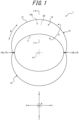
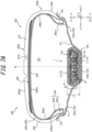
- FIG. 1 is a front view of a sound absorbing tool 1 as one of the disclosed embodiments of the sound absorbing tool according to this disclosure.
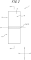
- FIG. 2 is a side view of the sound absorbing tool 1.
- FIG. 3 is a cross-sectional view of the sound absorbing tool 1 at the position of a line II-II in FIG. 2 .
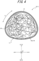
- FIG. 4 is a cross-sectional view of the sound absorbing tool 1 at the position of a line I-I in FIG. 1 .
- the sound absorbing tool 1 is placed on an annular outer surface of a rim.
- the use of the sound absorbing tool 1 can reduce resonance sound that is generated in a tire lumen during vehicle running.
- the sound absorbing tool 1 includes an endless housing body 10 and a sound absorbing material 20.
- a direction parallel to the central axis O1 is simply referred to as a "width direction A”.
- a direction around the central axis O1 is referred to as a "first circumferential direction B". That is, the first circumferential direction B means an extending direction in which the housing body 10 endlessly extends.
- a radial direction of a circle around the central axis O1 is referred to as a "radial direction C".
- a direction remote from the central axis O1 is referred to as an "outside C1 in the radial direction C"
- a direction approaching the central axis O1 is referred to as an "inside C2 in the radial direction C”.
- a direction around the endless axis O2 is referred to as a "second circumferential direction D”.
- the endless housing body 10 is configured to be stretchable in the first circumferential direction B. Therefore, the housing body 10 changes in length in the first circumferential direction by stretching in the first circumferential direction B.
- the housing body 10 internally defines a housing space 10a that can house the sound absorbing material 20.
- the sound absorbing material 20 is shapeless. The details are described later, but the shapeless sound absorbing material 20 may be, for example, a small piece group formed of a plurality of linear or granular small pieces.
- the sound absorbing material 20 is housed in the housing space 10a of the housing body 10. That is, the sound absorbing material 20 is housed in the housing space 10a inside the housing body 10 to be held in the housing body 10 in an outer shape tailored to the housing space 10a. In other words, the outer shape of the sound absorbing material 20 housed in the housing space 10a of the housing body 10 is deformable following the change of form of the housing body 10.
- the centrifugal force during vehicle running makes the housing body 10 be likely to elongate and deform in the first circumferential direction B.
- the sound absorbing material 20 housed in the housing space 10a of the housing body 10 is shapeless and thus can deform following the change of form of the housing body 10 that elongates in the first circumferential direction B, which is difficult to inhibit the elongation deformation of the housing body 10. Therefore, according to the sound absorbing tool 1, the housing body 10 elongates and deforms in the first circumferential direction B with respect to the centrifugal force during vehicle running, which can absorb the load applied on the sound absorbing tool 1. This can increase the durability during vehicle running of the sound absorbing tool 1.
- the housing body 10 of this embodiment includes: a housing portion 15 that defines the housing space 10a housing the sound absorbing material 20; and a connecting portion 16 that defines no housing space 10a, in the first circumferential direction B.
- the housing portion 15 includes: an inner wall 11 located at the inside C2 in the radial direction C across the housing space 10a; and an outer wall 12 located at the outside C1 in the radial direction C across the housing space 10a.
- the connecting portion 16 connects the ends in the first circumferential direction B of the housing portion 15.
- the housing body 10 of this embodiment includes a plurality of (two in this embodiment) housing portions 15 and a plurality of (two in this embodiment) connecting portions 16 located between the plurality of housing portions 15, in the first circumferential direction B.
- Each connecting portion 16 of this embodiment connects the ends of two housing portions 15 adjacent in the first circumferential direction B.
- the housing body 10 may be configured to include only one housing portion 15 in the first circumferential direction B. In such a case, the connecting portion 16 may connect both ends of only one housing portion 15.
- the housing body 10 of this embodiment may be formed by, for example, crashing a part in the first circumferential direction B of an endless tube material in the radial direction C to be bonded.
- the part crushed in the radial direction C and bonded of the endless tube material forms the above connecting portion 16.
- the part other than the connecting portion 16 forms the housing portion 15 that defines the housing space 10a.
- the method of forming the housing body 10 is not specifically limited.
- the housing body 10 may be obtained by, for example, connecting a plurality of bag bodies that form the respective housing portions 15 in the first circumferential direction B to be endless. In such a case, the part at which two bag bodies are connected to one another forms the above connecting portion 16.
- the inner wall 11 and the outer wall 12 have different stretchabilities in the first circumferential direction B.
- the inner wall 11 of the housing body 10 has lower stretchability in the first circumferential direction B than the outer wall 12 of the housing body 10.
- the stretchability here refers to an elongation percentage (%) obtained by an elongation percentage test based on Method B of the fabric test method for a woven fabric and a knitted fabric in JIS L 1096.
- the inner wall 11 of the housing body 10 is a part arranged on an annular outer surface side of a rim, in a state where the sound absorbing tool 1 is placed on the annular outer surface of the rim.
- the outer wall 12 of the housing body 10 is a part arranged on the side opposite to the annular outer surface side of the rim, in a state where the sound absorbing tool 1 is placed on the annular outer surface of the rim.
- the centrifugal force during vehicle running makes the inner wall 11 be less likely to excessively elongate in the first circumferential direction B. This can restrain the sound absorbing tool 1 from coming away from the rim.
- the centrifugal force during vehicle running makes the outer wall 12 be likely to elongate in the first circumferential direction B, which can absorb the load applied on the sound absorbing tool 1.
- the stretchabilities in the first circumferential direction B of the inner wall 11 and the outer wall 12 have the above relation, in addition to the increase in durability of the sound absorbing tool 1 based on the above load absorption performance by the sound absorbing tool 1, the placement stability to the rim of the sound absorbing tool 1 can be increased.
- the housing body 10 of this embodiment is stretchable in the second circumferential direction D.
- the housing body 10 is likely to elongate and deform in the second circumferential direction D due to the centrifugal force during vehicle running. Therefore, the housing body 10 can absorb the load applied on the sound absorbing tool 1 by elongating and deforming in the second circumferential direction D. This can more increase the durability during vehicle running of the sound absorbing tool 1.
- the housing body 10 elongating in the second circumferential direction D can expand the housing space 10a housing the sound absorbing material 20 to increase the sound absorbing performance during vehicle running by the sound absorbing material 20. This will be described below in detail (see FIG. 7A and FIG. 7B ).
- the inner wall 11 and the outer wall 12 have different stretchabilities in the second circumferential direction D.
- the inner wall 11 of the housing body 10 has lower stretchability in the second circumferential direction D than the outer wall 12 of the housing body 10.
- the stretchability here refers to an elongation percentage (%) obtained by an elongation percentage test based on Method B of the fabric test method for a woven fabric and a knitted fabric in JIS L 1096.
- the centrifugal force during vehicle running makes the inner wall 11 be less likely to excessively elongate in the second circumferential direction D.
- This can restrain the inner wall 11 of the housing body 10 from protruding to be convex toward the annular outer surface of the rim (downward in FIG. 4 ) in a cross-sectional view orthogonal to the first circumferential direction B (see FIG. 4 ). Therefore, the inner wall 11 of the housing body 10 becomes likely to maintain the shape along the annular outer surface of the rim.
- the centrifugal force during vehicle running makes the outer wall 12 be likely to elongate in the second circumferential direction D, which can absorb the load applied on the sound absorbing tool 1. That is, by making the stretchabilities in the second circumferential direction D of the inner wall 11 and the outer wall 12 have the above relation, in addition to the increase in durability of the sound absorbing tool 1 based on the above load absorption performance by the sound absorbing tool 1, the placement stability to the rim of the sound absorbing tool 1 can be increased.
- the housing body 10 of this embodiment is a woven fabric or a knitted fabric form of fibers such as polyethylene terephthalate fibers.
- the fibers that form the housing body 10 are not limited to the polyethylene terephthalate fibers and may be other resin fibers.
- the housing body 10 is not limited to a woven fabric or a knitted fabric so long as it has a configuration having stretchability at least in the first circumferential direction B, and its configuration is not specifically limited. However, as in this embodiment, the housing body 10 is preferably a woven fabric or a knitted fabric.
- Forming the housing body 10 of a woven fabric or a knitted fabric is likely to achieve desired stretchability in the first circumferential direction B, or in the first circumferential direction B and the second circumferential direction D. Forming the housing body 10 of a woven fabric or a knitted fabric is also likely to ensure the air permeability between the outside of the housing body 10 and the housing space 10a housing the sound absorbing material 20, through gaps between the fibers.
- the extending directions of orthogonal longitudinal fibers and transverse fibers are preferably inclined with respect to the first circumferential direction B and the second circumferential direction D. This can increase the stretchability in the first circumferential direction B and the second circumferential direction D even if the housing body 10 is a woven fabric.
- the inner wall 11 and the outer wall 12 have different stretchabilities.
- the above difference in stretchability may be achieved such that, for example, a part of the housing body 10 includes reinforcing fibers.
- the inner wall 11 of the housing body 10 of this embodiment internally includes reinforcing fibers 13a as a first inside reinforcing member 13 that extends in the first circumferential direction B.
- the outer wall 12 of the housing body 10 of this embodiment internally include no reinforcing fibers 13a that extend in the first circumferential direction B.
- the reinforcing fibers 13a of this embodiment are polyethylene terephthalate fibers but may be formed of another resin material. In this way, only the inner wall 11 including the reinforcing fibers 13a may differentiate the stretchabilities in the first circumferential direction B between the inner wall 11 and the outer wall 12 of the housing body 10.
- the reinforcing fibers 13a may be fibers that are stretchable themselves in the extending direction or fibers that are not stretchable themselves in the extending direction. When the reinforcing fibers 13a that do not stretch in the extending direction are employed, predetermined stretchability in the longitudinal direction can be achieved such that, for example, the reinforcing fibers 13a are configured to wavily extend in an unloaded state.
- the difference in stretchability in the first circumferential direction B in the inner wall 11 and the outer wall 12 of the housing body 10 is not limited to the difference in presence or absence of the above reinforcing fibers 13a.
- the difference in stretchability in the first circumferential direction B of the inner wall 11 and the outer wall 12 may be achieved by providing the reinforcing fibers 13a also in the outer wall 12 to differentiate the number of the reinforcing fibers 13a between the inner wall 11 and the outer wall 12.
- the first inside reinforcing member 13 having another configuration, such as a reinforcing film may be used (see FIG. 8 ).
- the means to achieve the difference in stretchability in the first circumferential direction B between the inner wall 11 and the outer wall 12 of the housing body 10 is not specifically limited.
- the inner wall 11 of the housing body 10 of this embodiment internally includes reinforcing fibers 14a as a second inside reinforcing member 14 that extends in the second circumferential direction D.
- the outer wall 12 of the housing body 10 of this embodiment internally includes no reinforcing fibers 14a that extend in the second circumferential direction D.
- the reinforcing fibers 14a of this embodiment are polyethylene terephthalate fibers but may be formed of another resin material. In this way, only the inner wall 11 including the reinforcing fibers 14a may differentiate the stretchability in the second circumferential direction D between the inner wall 11 and the outer wall 12 of the housing body 10.
- the reinforcing fibers 14a may be fibers that are stretchable themselves in the extending direction or fibers that are not stretchable themselves in the extending direction. When the reinforcing fibers 14a that do not stretch in the extending direction are employed, predetermined stretchability in the longitudinal direction can be achieved such that, for example, the reinforcing fibers 14a are configured to wavily extend in an unloaded state.
- the difference in stretchability in the second circumferential direction D between the inner wall 11 and the outer wall 12 of the housing body 10 is also not limited to the difference in presence or absence of the above reinforcing fibers 14a.
- the difference in stretchability in the second circumferential direction D between the inner wall 11 and the outer wall 12 may be achieved by providing the reinforcing fibers 14a also in the outer wall 12 to differentiate the number of the reinforcing fibers 14a between the inner wall 11 and the outer wall 12.
- the second inside reinforcing member 14 having another configuration, such as a reinforcing film may be used (see FIG. 8 ).
- the means to achieve the difference in stretchability in the second circumferential direction D between the inner wall 11 and the outer wall 12 of the housing body 10 is not specifically limited.
- the housing body 10 of this embodiment includes the housing portion 15 and the connecting portion 16 in the first circumferential direction B.
- the bending rigidity in a thickness direction E of the connecting portion 16 is smaller than the bending rigidity in the thickness direction E of the housing portion 15. That is, the connecting portion 16 can easily deform in the thickness direction E, compared with the housing portion 15. Therefore, as in this embodiment, the housing body 10 preferably includes a plurality of connecting portions 16.
- the plurality of connecting portions 16 preferably include a first connecting portion 16a and a second connecting portion 16b provided at the positions that are both ends of a flat length L2 of the housing body 10. This facilitates the compactification of the sound absorbing tool 1, which can increase the transportability of the sound absorbing tool 1. This will be described below in detail (see FIG. 6A and FIG. 6B ).
- the sound absorbing material 20 is housed in the housing space 10a of the housing body 10.
- the sound absorbing material 20 of this embodiment is shapeless stuffing, which is stuffed in the housing space 10a of the housing body 10.
- the shapeless sound absorbing material 20 is, for example, a small piece group including a plurality of linear or granular small pieces.
- the sound absorbing material 20 just has to have sound absorbing performance with the entire small piece group. Each of the small pieces is not required to have the sound absorbing performance.
- the sound absorbing material 20 being a small piece group including a plurality of linear or granular small pieces facilitates the adjustment of the amount of the sound absorbing material 20 housed in the housing space 10a of the housing body 10.
- the linear small pieces include small pieces of polyester fibers, such as small pieces of polyethylene terephthalate fibers.
- the outer shape of a cross-sectional surface orthogonal to the longitudinal direction of the linear small piece is not specifically limited.
- the cross-sectional outer shape of the linear small piece may be, for example, circle, oval, or polygonal.
- the linear small piece may be a tube body with a hollow portion or a solid body without a hollow portion.
- Examples of a small piece group formed of the linear small pieces include cotton made of polyester fibers.
- Examples of the granular small piece include a foam resin small piece such as a urethane foam small piece; and a resin small piece such as a polyethylene pipe small piece.
- the small pieces that form the sound absorbing material 20 are not limited to the above exemplified small pieces.
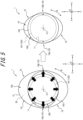
- FIG. 5 is an explanatory drawing illustrating a mounting method of mounting the sound absorbing tool 1 of this embodiment on an annular outer surface 101 of the rim 100.
- the housing body 10 of the sound absorbing tool 1 is configured to be stretchable in the first circumferential direction B. Moreover, the sound absorbing material 20 housed in the housing space 10a of the housing body 10 is shapeless and thus likely to deform following the deformation of the housing body 10. Therefore, as illustrated in FIG. 5 , the sound absorbing tool 1 can easily extend the housing body 10 in which the housing space 10a houses the sound absorbing material 20, from the inside C2 toward the outside C1 in the radial direction C (see a thick-line arrow in the left figure in FIG. 5 ).
- the rim 100 includes: an annular portion 102 including the annular outer surface 101; and rim flange portions 103 protruding from both ends of the annular portion 102 to the outside in a rim radial direction.
- the sound absorbing tool 1 of this embodiment can easily cross over the rim flange portion 103 of the rim 100 by extending the housing body 10 from the inside C2 toward the outside C1 in the radial direction C (see the left figure in FIG. 5 ).
- the sound absorbing tool 1 of this embodiment can be easily placed on the annular outer surface 101 of the rim 100 by using the stretchability in the first circumferential direction B of the housing body 10.
- FIG. 6A is a drawing illustrating a state where the sound absorbing tool 1 of this embodiment is folded to be flattened at the positions of the connecting portions 16 of the housing body 10.
- FIG. 6B is a drawing illustrating a state where the sound absorbing tool 1 illustrated in FIG. 6A is further compressed to be packed by a packing material.
- the housing body 10 of the sound absorbing tool 1 is configured to be stretchable in the first circumferential direction B.
- the sound absorbing material 20 housed in the housing space 10a of the housing body 10 is shapeless and thus likely to deform following the deformation of the housing body 10. Therefore, as illustrated in FIG. 6A and FIG. 6B , the sound absorbing tool 1 is depressed from the outside C1 toward the inside C2 in the radial direction C, which flattens the housing body 10 and compresses the sound absorbing material 20, thus easily flattening the sound absorbing tool 1. Therefore, when the sound absorbing tool 1 is transported alone, the sound absorbing tool 1 can be compactified to increase the transportability.
- the bending rigidity in the thickness direction E of the connecting portion 16 of the housing body 10 is smaller than the bending rigidity in the thickness direction E of the housing portion 15 of the housing body 10. Furthermore, in the sound absorbing tool 1 of this embodiment, in a state where the sound absorbing material 20 is housed in the housing space 10a of the housing portion 15, a maximum thickness T1 of the connecting portion 16 is thinner than a maximum thickness T2 of the housing portion 15.
- the housing body 10 preferably includes a first connecting portion 16a and a second connecting portion 16b provided at the positions to be both ends of the flat length L2. This makes the sound absorbing tool 1 be likely to be flattened such that the first connecting portion 16a and the second connecting portion 16b are both ends of the flat length L2, without substantially receiving the restoring force of the sound absorbing material 20, as illustrated in FIG. 6A .
- the sound absorbing tool 1 may be further flattened as illustrated in FIG. 6B .
- FIG. 6B by vacuum-packing the sound absorbing tool 1 by a packing material 110 in a state where the sound absorbing material 20 is compressed, the sound absorbing tool 1 can be more compactified. This can further increase the transportability of the sound absorbing tool 1.
- FIG. 7A and FIG. 7B are each a cross-sectional view in the tire width direction illustrating a cross-sectional surface through the tire rotation axis and along the tire width direction, of the assembly 300.
- FIG. 7A is a cross-sectional view in the tire width direction of the assembly 300, during non-rotation when the assembly 300 is not rotating in the tire circumferential direction.
- FIG. 7A is a cross-sectional view in the tire width direction of the assembly 300, during non-rotation when the assembly 300 is not rotating in the tire circumferential direction.
- FIG. 7B is a cross-sectional view in the tire width direction of the assembly 300, during rotation when the assembly 300 is rotating in the tire circumferential direction.
- the cross-sectional surface of the sound absorbing tool 1 is a cross-sectional surface orthogonal to the first circumferential direction B.
- the width direction of the tire 200 in the assembly 300 is referred to as a "tire width direction F”.
- the direction around the central axis of the tire 200 in the assembly 300 is referred to as a "tire circumferential direction G”.
- the radial direction of a circle around the central axis of the tire 200 in the assembly 300 is referred to as a "tire radial direction H".
- the rim 100 includes: the annular portion 102 including the annular outer surface 101; and the rim flange portions 103, as described above.
- the annular portion 102 includes: a pair of bead sheet portions 102a located at both ends in the tire width direction F; and a well portion 102b placed between the pair of bead sheet portions 102a in the tire width direction F and recessed inside the bead sheet portions 102a in the tire radial direction H.
- the rim flange portion 103 protrudes from the outside end in the tire width direction F of the bead sheet portion 102a of the annular portion 102 toward the outside in the tire radial direction H.
- the "rim” herein is an approved rim ("Measuring Rim” in The European Tyre and Rim Technical Organisation (ETRTO) STANDARDS MANUAL, "Design Rim” in The Tire and Rim Association, Inc. (TRA) YEAR BOOK) in applicable size described or to be described in future in an effective industrial standard in areas where tires are produced or used, such as Japan Automobile Tyre Manufacturers Association (JATMA) YEAR BOOK in Japan, ETRTO STANDARDS MANUAL in Europe, or TRA YEAR BOOK in the United States.
- the rim refers to a rim having a width corresponding to a bead width of the tire.
- the “rim” includes sizes that can be described in future in the above industrial standard, in addition to the current sizes.
- Examples of “the size to be described in future” include sizes described as “FUTURE DEVELOPMENTS” in 2013 edition of ETRTO STANDARDS MANUAL.
- the tire 200 As illustrated in FIG. 7A and FIG. 7B , the tire 200 is mounted on the rim 100.
- the dimensions, length relationships, the positional relationships, etc. of respective components will be measured in a reference state where a pneumatic tire as the tire 200 is mounted on the rim 100 and filled with a prescribed internal pressure to have no load.
- the "prescribed internal pressure” indicates an air pressure (maximum air pressure) corresponding to a maximum load capability of a single wheel in an applicable size and ply rating described in JATMA YEAR BOOK or the like as described above.
- the "prescribed internal pressure” refers to an air pressure (maximum air pressure) corresponding to the maximum load capability prescribed for each vehicle on which the tire is mounted.
- the "maximum load” indicates a load corresponding to the above tire maximum load capability of the standard of JATMA or the like in the tire of the applicable size, or the maximum load having a size that is not described in the above industrial standard indicates a load corresponding to the maximum load capability prescribed for each vehicle on which the tire is mounted.
- the tire 200 of this embodiment is a passenger vehicle tire but may be, for example, a tire for truck and bus.
- the type, application, and the like of the vehicle to be applied are not specifically limited.
- the tire 200 includes: a tread portion 200a; a pair of sidewall portions 200b extending from both ends in the tire width direction F of the tread portion 200a to the inside in the tire radial direction H; and a pair of bead portions 200c each provided at the end inside in the tire radial direction H of each sidewall portion 200b.
- the tire 200 of this embodiment is a tubeless-type radial tire.
- the tire 200 has a tire lumen 201 defined by a tread inner surface 200a1 that is the inner surface of the tread portion 200a; sidewall inner surfaces 200b1 that are the inner surfaces of the sidewall portions 200b; and bead inner surfaces 200c1 that are the inner surfaces of the bead portions 200c.
- the tire 200 includes a bead member 204, a carcass 205, a belt 206, a tread rubber 207, a side rubber 208, and an inner liner 209.
- the bead member 204 is buried in the bead portion 200c.
- the bead member 204 includes a bead core 204a and a rubber bead filler 204b located outside in the tire radial direction H with respect to the bead core 204a.
- the bead core 204a includes a plurality of bead wires surrounded by rubber coating.
- the bead wire may be formed of, for example, a steel cord.
- the steel cord can be made of, for example, steel monofilaments or stranded wires.
- organic fibers, carbon fibers, or the like may be used as the bead wire.
- the carcass 205 straddles between the pair of bead portions 200c, more specifically, between the bead cores 204a of the pair of bead members 204 and extends in a toroidal shape. More specifically, the carcass 205 of this embodiment includes one or more (one in this embodiment) carcass plies 205a in which carcass cords are arranged at an angle of, for example, 75° to 90° with respect to the tire circumferential direction G.
- the carcass ply 205a includes: a ply main body 205a1 located between the pair of bead cores 204a; and ply folded portions 205a2 that are folded from the inside to the outside in the tire width direction F around the bead cores 204a at both ends of the ply main body 205a1.
- the bead filler 204b that extends in a tapered shape from the bead core 204a to the outside in the tire radial direction H is arranged between the ply main body 205a1 and the ply folded portion 205a2.
- the carcass cords that form the carcass ply 205a may be, for example, metal cords such as steel cords or may be organic fiber cords such as nylon.
- the carcass 205 may include a plurality of carcass plies 205a.
- the belt 206 includes one or more (five in this embodiment) belt layers arranged outside in the tire radial direction H with respect to the crown portion of the carcass 205.
- Each belt layer may be an inclined belt layer with an angle of 10° or more with respect to the tire circumferential direction G of the belt cord or may be a circumferential belt layer with an angle of less than 10° with respect to the tire circumferential direction G of the belt cord.
- the tread rubber 207 forms a tread outer surface 200a2 that is the outer surface of the tread portion 200a.
- a tread pattern including a circumferential groove 207a extending in the tire circumferential direction G and a width direction groove (not illustrated) extending in the tire width direction F, and the like is formed on the tread outer surface 200a2.
- the side rubber 208 forms the outside surface in the tire width direction F of the sidewall portion 200b and are continuous with the end in the tire width direction F of the above tread rubber 207.
- the inner liner 209 is stacked on the inner surface of the carcass 205.
- the inner liner 209 may be formed of, for example, a butyl-based rubber with low air permeability.
- the sound absorbing tool 1 is supported by the rim 100, on the annular outer surface 101 of the rim 100, inside the tire 200. More specifically, in the assembly 300 of this embodiment, the sound absorbing tool 1 is placed on the annular outer surface 101 at the position of the well portion 102b of the annular portion 102.
- the sound absorbing tool 1 is wound around the rim 100 such that the inner wall 11 of the housing body 10 faces the inside in the tire radial direction H to be in contact with the annular outer surface 101.
- the sound absorbing tool 1 is wound around the rim 100 such that the outer wall 12 of the housing body 10 faces the outside in the tire radial direction H to be opposed to the tread inner surface 200a1 of the tire 200.
- the housing body 10 of the sound absorbing tool 1 elongates in the first circumferential direction B and the second circumferential direction D due to the above centrifugal force during the rotation of the assembly 300 to expand the housing space 10a. This also increases the volume of the sound absorbing material 20 of the housing space 10a.
- the sound absorbing tool 1 can decrease a height L3 in the tire radial direction H during the non-rotation of the assembly 300 (see FIG. 7A ). This makes the sound absorbing tool 1 be less likely to be an obstacle when the tire 200 is mounted on the rim 100.
- the sound absorbing tool 1 increases its volume to increase the height L3 in the tire radial direction H during the rotation of the assembly 300 (see FIG. 7B ). This is because the housing body 10 elongates in the second circumferential direction D due to the centrifugal force. This also increases the volume of the sound absorbing material 20 of the housing space 10a to increase air gaps in the sound absorbing material 20, which increases the sound absorbing performance. Moreover, the volume of the sound absorbing tool 1 increases during the rotation of the assembly 300 (see FIG. 7B ), which accordingly decreases the cavity of the tire lumen 201. That is, the decrease in the cavity in which the resonance sound is generated can restrain the generated resonance sound itself.
- the sound absorbing tool 1 can achieve a balance of the increase in mountability when the tire 200 is attached to and mounted on the rim 100 and the increase in sound absorbability during vehicle running with the assembly 300 rotating.
- the outside end in the tire radial direction H of the sound absorbing tool 1 of the assembly 300 of this embodiment is located inside in the tire radial direction H with respect to an inside end P1 in the tire radial direction H of the tire 200 during the non-rotation of the assembly 300.
- the outside end in the tire radial direction H of the sound absorbing tool 1 of the assembly 300 of this embodiment is located outside in the tire radial direction H with respect to the inside end P1 in the tire radial direction H of the tire 200 during the rotation of the assembly 300.
- the rotation of the assembly 300 causes the sound absorbing tool 1 to expand from the inside to the outside in the tire radial direction H so as to cross the position in the tire radial direction H of the inside end P1 in the tire radial direction H of the tire 200.
- the outside end in the tire radial direction H of the sound absorbing tool 1 is a part of the outer wall 12 of the housing body 10. This facilitates the achievement of the above balance of the mounting performance and the sound absorbing performance.
- the sound absorbing tool and the assembly according to this disclosure are not limited to the specific configurations described in the above embodiments, and various variants, changes, and combinations are possible without departing from the claims.
- the above sound absorbing tool 1 has a configuration including two housing portions 15 and two connecting portions 16 in the first circumferential direction B.
- the sound absorbing tool 1 may have a configuration including three or more (four in FIG. 8 ) housing portions 15 and three or more (four in FIG. 8 ) connecting portions 16 in the first circumferential direction B.
- the above housing body 10 has a configuration in which the inner wall 11 includes the reinforcing fibers 13a and 14a.
- the housing body 10 may have a configuration in which the inner wall 11 includes a reinforcing film 17 as at least one of the first inside reinforcing member 13 and the second inside reinforcing member 14.
- This disclosure relates to a sound absorbing tool and an assembly.
Landscapes
- Engineering & Computer Science (AREA)
- Mechanical Engineering (AREA)
- Tires In General (AREA)
Abstract
Description
- This disclosure relates to a sound absorbing tool and an assembly.
- Conventionally, there is known a technique of arranging a sound absorbing material formed of a foam body in a tire lumen between a rim of a wheel in a vehicle and a tire. This technique can cause the sound absorbing material to reduce resonance sound that is generated in the tire lumen.
PTL 1 discloses a sound absorbing tool including this kind of sound absorbing material formed of a foam body. - The sound absorbing tool disclosed in
PTL 1 includes a band-shaped backplane formed of a stainless plate. The backplane inPTL 1 has locking portions at both ends. The sound absorbing tool disclosed inPTL 1 is wound along a tire locking ring groove of a wheel, and the locking portions at both ends of the backplane are connected and fixed one another. This attaches the sound absorbing tool disclosed inPTL 1 to the wheel. - PTL 1:
JPH09-86102A - However, in the sound absorbing tool disclosed in
PTL 1, the backplane formed of a stainless plate has high rigidity, and the centrifugal force or the like during vehicle running is thus likely to increase the load on the locking portions. Therefore, there is a problem that the locking portions of the backplane are likely to break during vehicle running. - It could be helpful to provide a sound absorbing tool that can increase the durability during vehicle running, and an assembly.
- A sound absorbing tool as a first aspect of this disclosure includes: an endless housing body that internally defines a housing space and is stretchable in a circumferential direction; and a shapeless sound absorbing material that is housed in the housing space of the housing body.
- An assembly as a second aspect of this disclosure includes a rim and a tire mounted on the rim, and the assembly includes the above sound absorbing tool that is supported by the rim on an annular outer surface of the rim, inside the tire.
- This disclosure can provide a sound absorbing tool that can increase the durability during vehicle running, and an assembly.
- In the accompanying drawings:
-
FIG. 1 is a front view of a sound absorbing tool as one of the disclosed embodiments; -
FIG. 2 is a side view of the sound absorbing tool illustrated inFIG. 1 ; -
FIG. 3 is a cross-sectional view at the position of a line II-II inFIG. 2 ; -
FIG. 4 is a cross-sectional view at the position of a line I-I inFIG. 1 ; -
FIG. 5 is an explanatory drawing illustrating a mounting method of mounting the sound absorbing tool illustrated inFIG. 1 on an annular outer surface of a rim; -
FIG. 6A is a drawing illustrating a state where the sound absorbing tool illustrated inFIG. 1 is folded to be flattened at the positions of connecting portions of a housing body; -
FIG. 6B is a drawing illustrating a state where the sound absorbing tool illustrated inFIG. 6A is further compressed to be packed by a packing material; -
FIG. 7A is a cross-sectional view in a tire width direction during non-rotation when an assembly as one of the embodiments is not rotating in a tire circumferential direction; -
FIG. 7B is a cross-sectional view in the tire width direction during rotation when the assembly illustrated inFIG. 7A is rotating in the tire circumferential direction; and -
FIG. 8 is a drawing illustrating a variant of the sound absorbing tool illustrated inFIG. 1 . - Embodiments of a sound absorbing tool and an assembly according to this disclosure will be exemplified and described hereinafter with reference to the drawings. Configurations common between the figures have the same reference signs.
-
FIG. 1 is a front view of asound absorbing tool 1 as one of the disclosed embodiments of the sound absorbing tool according to this disclosure.FIG. 2 is a side view of thesound absorbing tool 1.FIG. 3 is a cross-sectional view of thesound absorbing tool 1 at the position of a line II-II inFIG. 2 .FIG. 4 is a cross-sectional view of thesound absorbing tool 1 at the position of a line I-I inFIG. 1 . - The details are described later, but the
sound absorbing tool 1 is placed on an annular outer surface of a rim. The use of thesound absorbing tool 1 can reduce resonance sound that is generated in a tire lumen during vehicle running. - As illustrated in
FIG. 1 to FIG. 4 , thesound absorbing tool 1 includes anendless housing body 10 and asound absorbing material 20. - Hereinafter, for the sake of explanation, when a central axis O1 (see
FIG. 1 , etc.) that penetrates a central opening of theendless housing body 10 is set, a direction parallel to the central axis O1 is simply referred to as a "width direction A". Moreover, a direction around the central axis O1 is referred to as a "first circumferential direction B". That is, the first circumferential direction B means an extending direction in which thehousing body 10 endlessly extends. Furthermore, a radial direction of a circle around the central axis O1 is referred to as a "radial direction C". Of the radial direction C, a direction remote from the central axis O1 is referred to as an "outside C1 in the radial direction C", and a direction approaching the central axis O1 is referred to as an "inside C2 in the radial direction C". Moreover, when an endless axis O2 (seeFIG. 4 ) along the first circumferential direction B is set, a direction around the endless axis O2 is referred to as a "second circumferential direction D". - The
endless housing body 10 is configured to be stretchable in the first circumferential direction B. Therefore, thehousing body 10 changes in length in the first circumferential direction by stretching in the first circumferential direction B. Thehousing body 10 internally defines ahousing space 10a that can house thesound absorbing material 20. - The
sound absorbing material 20 is shapeless. The details are described later, but the shapelesssound absorbing material 20 may be, for example, a small piece group formed of a plurality of linear or granular small pieces. Thesound absorbing material 20 is housed in thehousing space 10a of thehousing body 10. That is, thesound absorbing material 20 is housed in thehousing space 10a inside thehousing body 10 to be held in thehousing body 10 in an outer shape tailored to thehousing space 10a. In other words, the outer shape of thesound absorbing material 20 housed in thehousing space 10a of thehousing body 10 is deformable following the change of form of thehousing body 10. - According to such a
sound absorbing tool 1, the centrifugal force during vehicle running makes thehousing body 10 be likely to elongate and deform in the first circumferential direction B. Thesound absorbing material 20 housed in thehousing space 10a of thehousing body 10 is shapeless and thus can deform following the change of form of thehousing body 10 that elongates in the first circumferential direction B, which is difficult to inhibit the elongation deformation of thehousing body 10. Therefore, according to thesound absorbing tool 1, thehousing body 10 elongates and deforms in the first circumferential direction B with respect to the centrifugal force during vehicle running, which can absorb the load applied on thesound absorbing tool 1. This can increase the durability during vehicle running of thesound absorbing tool 1. - Hereinafter, further details of the
sound absorbing tool 1 of this embodiment will be described. - As illustrated in
FIG. 1 andFIG. 3 , thehousing body 10 of this embodiment includes: ahousing portion 15 that defines thehousing space 10a housing thesound absorbing material 20; and a connectingportion 16 that defines nohousing space 10a, in the first circumferential direction B. - The
housing portion 15 includes: aninner wall 11 located at the inside C2 in the radial direction C across thehousing space 10a; and anouter wall 12 located at the outside C1 in the radial direction C across thehousing space 10a. - The connecting
portion 16 connects the ends in the first circumferential direction B of thehousing portion 15. As illustrated inFIG. 1 andFIG. 3 , thehousing body 10 of this embodiment includes a plurality of (two in this embodiment)housing portions 15 and a plurality of (two in this embodiment) connectingportions 16 located between the plurality ofhousing portions 15, in the first circumferential direction B. Each connectingportion 16 of this embodiment connects the ends of twohousing portions 15 adjacent in the first circumferential direction B. However, thehousing body 10 may be configured to include only onehousing portion 15 in the first circumferential direction B. In such a case, the connectingportion 16 may connect both ends of only onehousing portion 15. - The
housing body 10 of this embodiment may be formed by, for example, crashing a part in the first circumferential direction B of an endless tube material in the radial direction C to be bonded. In such a case, the part crushed in the radial direction C and bonded of the endless tube material forms the above connectingportion 16. Moreover, in the first circumferential direction B, the part other than the connectingportion 16 forms thehousing portion 15 that defines thehousing space 10a. However, the method of forming thehousing body 10 is not specifically limited. Thehousing body 10 may be obtained by, for example, connecting a plurality of bag bodies that form therespective housing portions 15 in the first circumferential direction B to be endless. In such a case, the part at which two bag bodies are connected to one another forms the above connectingportion 16. - In the
housing body 10 of this embodiment, theinner wall 11 and theouter wall 12 have different stretchabilities in the first circumferential direction B. Specifically, theinner wall 11 of thehousing body 10 has lower stretchability in the first circumferential direction B than theouter wall 12 of thehousing body 10. The stretchability here refers to an elongation percentage (%) obtained by an elongation percentage test based on Method B of the fabric test method for a woven fabric and a knitted fabric in JIS L 1096. - The
inner wall 11 of thehousing body 10 is a part arranged on an annular outer surface side of a rim, in a state where thesound absorbing tool 1 is placed on the annular outer surface of the rim. In contrast, theouter wall 12 of thehousing body 10 is a part arranged on the side opposite to the annular outer surface side of the rim, in a state where thesound absorbing tool 1 is placed on the annular outer surface of the rim. - By decreasing the stretchability in the first circumferential direction B of the
inner wall 11, the centrifugal force during vehicle running makes theinner wall 11 be less likely to excessively elongate in the first circumferential direction B. This can restrain thesound absorbing tool 1 from coming away from the rim. Conversely, by increasing the stretchability in the first circumferential direction B of theouter wall 12, the centrifugal force during vehicle running makes theouter wall 12 be likely to elongate in the first circumferential direction B, which can absorb the load applied on thesound absorbing tool 1. That is, by making the stretchabilities in the first circumferential direction B of theinner wall 11 and theouter wall 12 have the above relation, in addition to the increase in durability of thesound absorbing tool 1 based on the above load absorption performance by thesound absorbing tool 1, the placement stability to the rim of thesound absorbing tool 1 can be increased. - Moreover, the
housing body 10 of this embodiment is stretchable in the second circumferential direction D. With such a configuration, thehousing body 10 is likely to elongate and deform in the second circumferential direction D due to the centrifugal force during vehicle running. Therefore, thehousing body 10 can absorb the load applied on thesound absorbing tool 1 by elongating and deforming in the second circumferential direction D. This can more increase the durability during vehicle running of thesound absorbing tool 1. - Furthermore, the
housing body 10 elongating in the second circumferential direction D can expand thehousing space 10a housing thesound absorbing material 20 to increase the sound absorbing performance during vehicle running by thesound absorbing material 20. This will be described below in detail (seeFIG. 7A andFIG. 7B ). - More specifically, in the
housing body 10 of this embodiment, theinner wall 11 and theouter wall 12 have different stretchabilities in the second circumferential direction D. Theinner wall 11 of thehousing body 10 has lower stretchability in the second circumferential direction D than theouter wall 12 of thehousing body 10. The stretchability here refers to an elongation percentage (%) obtained by an elongation percentage test based on Method B of the fabric test method for a woven fabric and a knitted fabric in JIS L 1096. - By decreasing the stretchability in the second circumferential direction D of the
inner wall 11, the centrifugal force during vehicle running makes theinner wall 11 be less likely to excessively elongate in the second circumferential direction D. This can restrain theinner wall 11 of thehousing body 10 from protruding to be convex toward the annular outer surface of the rim (downward inFIG. 4 ) in a cross-sectional view orthogonal to the first circumferential direction B (seeFIG. 4 ). Therefore, theinner wall 11 of thehousing body 10 becomes likely to maintain the shape along the annular outer surface of the rim. Conversely, by increasing the stretchability in the second circumferential direction D of theouter wall 12, the centrifugal force during vehicle running makes theouter wall 12 be likely to elongate in the second circumferential direction D, which can absorb the load applied on thesound absorbing tool 1. That is, by making the stretchabilities in the second circumferential direction D of theinner wall 11 and theouter wall 12 have the above relation, in addition to the increase in durability of thesound absorbing tool 1 based on the above load absorption performance by thesound absorbing tool 1, the placement stability to the rim of thesound absorbing tool 1 can be increased. - The
housing body 10 of this embodiment is a woven fabric or a knitted fabric form of fibers such as polyethylene terephthalate fibers. The fibers that form thehousing body 10 are not limited to the polyethylene terephthalate fibers and may be other resin fibers. Thehousing body 10 is not limited to a woven fabric or a knitted fabric so long as it has a configuration having stretchability at least in the first circumferential direction B, and its configuration is not specifically limited. However, as in this embodiment, thehousing body 10 is preferably a woven fabric or a knitted fabric. Forming thehousing body 10 of a woven fabric or a knitted fabric is likely to achieve desired stretchability in the first circumferential direction B, or in the first circumferential direction B and the second circumferential direction D. Forming thehousing body 10 of a woven fabric or a knitted fabric is also likely to ensure the air permeability between the outside of thehousing body 10 and thehousing space 10a housing thesound absorbing material 20, through gaps between the fibers. - When the
housing body 10 is a woven fabric, the extending directions of orthogonal longitudinal fibers and transverse fibers are preferably inclined with respect to the first circumferential direction B and the second circumferential direction D. This can increase the stretchability in the first circumferential direction B and the second circumferential direction D even if thehousing body 10 is a woven fabric. - As described above, in the
housing body 10 of this embodiment, theinner wall 11 and theouter wall 12 have different stretchabilities. In thehousing body 10 that is a woven fabric or a knitted fabric, the above difference in stretchability may be achieved such that, for example, a part of thehousing body 10 includes reinforcing fibers. As illustrated inFIG. 4 , theinner wall 11 of thehousing body 10 of this embodiment internally includes reinforcing fibers 13a as a first inside reinforcingmember 13 that extends in the first circumferential direction B. Conversely, theouter wall 12 of thehousing body 10 of this embodiment internally include no reinforcing fibers 13a that extend in the first circumferential direction B. The reinforcing fibers 13a of this embodiment are polyethylene terephthalate fibers but may be formed of another resin material. In this way, only theinner wall 11 including the reinforcing fibers 13a may differentiate the stretchabilities in the first circumferential direction B between theinner wall 11 and theouter wall 12 of thehousing body 10. The reinforcing fibers 13a may be fibers that are stretchable themselves in the extending direction or fibers that are not stretchable themselves in the extending direction. When the reinforcing fibers 13a that do not stretch in the extending direction are employed, predetermined stretchability in the longitudinal direction can be achieved such that, for example, the reinforcing fibers 13a are configured to wavily extend in an unloaded state. - The difference in stretchability in the first circumferential direction B in the
inner wall 11 and theouter wall 12 of thehousing body 10 is not limited to the difference in presence or absence of the above reinforcing fibers 13a. For example, the difference in stretchability in the first circumferential direction B of theinner wall 11 and theouter wall 12 may be achieved by providing the reinforcing fibers 13a also in theouter wall 12 to differentiate the number of the reinforcing fibers 13a between theinner wall 11 and theouter wall 12. Moreover, to differentiate the stretchability in the first circumferential direction B between theinner wall 11 and theouter wall 12 of thehousing body 10, the first inside reinforcingmember 13 having another configuration, such as a reinforcing film, may be used (seeFIG. 8 ). Furthermore, not only the presence or absence of the first inside reinforcingmember 13, but also, for example, forming theinner wall 11 and theouter wall 12 of different materials having different stretchabilities may differentiate the stretchability in the first circumferential direction B between theinner wall 11 and theouter wall 12. In this way, the means to achieve the difference in stretchability in the first circumferential direction B between theinner wall 11 and theouter wall 12 of thehousing body 10 is not specifically limited. - As illustrated in
FIG. 3 , theinner wall 11 of thehousing body 10 of this embodiment internally includes reinforcingfibers 14a as a second inside reinforcingmember 14 that extends in the second circumferential direction D. Conversely, theouter wall 12 of thehousing body 10 of this embodiment internally includes no reinforcingfibers 14a that extend in the second circumferential direction D. The reinforcingfibers 14a of this embodiment are polyethylene terephthalate fibers but may be formed of another resin material. In this way, only theinner wall 11 including the reinforcingfibers 14a may differentiate the stretchability in the second circumferential direction D between theinner wall 11 and theouter wall 12 of thehousing body 10. The reinforcingfibers 14a may be fibers that are stretchable themselves in the extending direction or fibers that are not stretchable themselves in the extending direction. When the reinforcingfibers 14a that do not stretch in the extending direction are employed, predetermined stretchability in the longitudinal direction can be achieved such that, for example, the reinforcingfibers 14a are configured to wavily extend in an unloaded state. - The difference in stretchability in the second circumferential direction D between the
inner wall 11 and theouter wall 12 of thehousing body 10 is also not limited to the difference in presence or absence of the above reinforcingfibers 14a. For example, the difference in stretchability in the second circumferential direction D between theinner wall 11 and theouter wall 12 may be achieved by providing the reinforcingfibers 14a also in theouter wall 12 to differentiate the number of the reinforcingfibers 14a between theinner wall 11 and theouter wall 12. Moreover, to differentiate the stretchability in the second circumferential direction D between theinner wall 11 and theouter wall 12 of thehousing body 10, the second inside reinforcingmember 14 having another configuration, such as a reinforcing film, may be used (seeFIG. 8 ). Furthermore, not only the presence or absence of the second inside reinforcingmember 14, but also, for example, forming theinner wall 11 and theouter wall 12 of different materials having different stretchabilities may differentiate the stretchability in the second circumferential direction D between theinner wall 11 and theouter wall 12. In this way, the means to achieve the difference in stretchability in the second circumferential direction D between theinner wall 11 and theouter wall 12 of thehousing body 10 is not specifically limited. - As described above, the
housing body 10 of this embodiment includes thehousing portion 15 and the connectingportion 16 in the first circumferential direction B. In this embodiment, in a state where thesound absorbing material 20 is housed in thehousing space 10a of thehousing portion 15, the bending rigidity in a thickness direction E of the connectingportion 16 is smaller than the bending rigidity in the thickness direction E of thehousing portion 15. That is, the connectingportion 16 can easily deform in the thickness direction E, compared with thehousing portion 15. Therefore, as in this embodiment, thehousing body 10 preferably includes a plurality of connectingportions 16. In particular, as in this embodiment, the plurality of connectingportions 16 preferably include a first connectingportion 16a and a second connectingportion 16b provided at the positions that are both ends of a flat length L2 of thehousing body 10. This facilitates the compactification of thesound absorbing tool 1, which can increase the transportability of thesound absorbing tool 1. This will be described below in detail (seeFIG. 6A andFIG. 6B ). - As illustrated in
FIG. 3 andFIG. 4 , thesound absorbing material 20 is housed in thehousing space 10a of thehousing body 10. Thesound absorbing material 20 of this embodiment is shapeless stuffing, which is stuffed in thehousing space 10a of thehousing body 10. - The shapeless
sound absorbing material 20 is, for example, a small piece group including a plurality of linear or granular small pieces. Thesound absorbing material 20 just has to have sound absorbing performance with the entire small piece group. Each of the small pieces is not required to have the sound absorbing performance. Thesound absorbing material 20 being a small piece group including a plurality of linear or granular small pieces facilitates the adjustment of the amount of thesound absorbing material 20 housed in thehousing space 10a of thehousing body 10. Examples of the linear small pieces include small pieces of polyester fibers, such as small pieces of polyethylene terephthalate fibers. The outer shape of a cross-sectional surface orthogonal to the longitudinal direction of the linear small piece is not specifically limited. The cross-sectional outer shape of the linear small piece may be, for example, circle, oval, or polygonal. The linear small piece may be a tube body with a hollow portion or a solid body without a hollow portion. Examples of a small piece group formed of the linear small pieces include cotton made of polyester fibers. Examples of the granular small piece include a foam resin small piece such as a urethane foam small piece; and a resin small piece such as a polyethylene pipe small piece. However, the small pieces that form thesound absorbing material 20 are not limited to the above exemplified small pieces. - The following describes a method of mounting the
sound absorbing tool 1 of this embodiment on arim 100, with reference toFIG. 5. FIG. 5 is an explanatory drawing illustrating a mounting method of mounting thesound absorbing tool 1 of this embodiment on an annularouter surface 101 of therim 100. - As described above, the
housing body 10 of thesound absorbing tool 1 is configured to be stretchable in the first circumferential direction B. Moreover, thesound absorbing material 20 housed in thehousing space 10a of thehousing body 10 is shapeless and thus likely to deform following the deformation of thehousing body 10. Therefore, as illustrated inFIG. 5 , thesound absorbing tool 1 can easily extend thehousing body 10 in which thehousing space 10a houses thesound absorbing material 20, from the inside C2 toward the outside C1 in the radial direction C (see a thick-line arrow in the left figure inFIG. 5 ). - As illustrated in
FIG. 5 , therim 100 includes: anannular portion 102 including the annularouter surface 101; andrim flange portions 103 protruding from both ends of theannular portion 102 to the outside in a rim radial direction. Thesound absorbing tool 1 of this embodiment can easily cross over therim flange portion 103 of therim 100 by extending thehousing body 10 from the inside C2 toward the outside C1 in the radial direction C (see the left figure inFIG. 5 ). After thesound absorbing tool 1 crosses over therim flange portion 103, the external force that has been applied to thehousing body 10 from the inside C2 toward the outside C1 in the radial direction C is released, which causes thehousing body 10 to deform by the restoring force from the outside C1 toward the inside C2 in the radial direction C to be supported on the annularouter surface 101 of the annular portion 102 (see the right figure inFIG. 5 ). - That is, the
sound absorbing tool 1 of this embodiment can be easily placed on the annularouter surface 101 of therim 100 by using the stretchability in the first circumferential direction B of thehousing body 10. - The following describes the transportability of the
sound absorbing tool 1 of this embodiment, with reference toFIG. 6A andFIG. 6B .FIG. 6A is a drawing illustrating a state where thesound absorbing tool 1 of this embodiment is folded to be flattened at the positions of the connectingportions 16 of thehousing body 10.FIG. 6B is a drawing illustrating a state where thesound absorbing tool 1 illustrated inFIG. 6A is further compressed to be packed by a packing material. - As described above, the
housing body 10 of thesound absorbing tool 1 is configured to be stretchable in the first circumferential direction B. Moreover, thesound absorbing material 20 housed in thehousing space 10a of thehousing body 10 is shapeless and thus likely to deform following the deformation of thehousing body 10. Therefore, as illustrated inFIG. 6A andFIG. 6B , thesound absorbing tool 1 is depressed from the outside C1 toward the inside C2 in the radial direction C, which flattens thehousing body 10 and compresses thesound absorbing material 20, thus easily flattening thesound absorbing tool 1. Therefore, when thesound absorbing tool 1 is transported alone, thesound absorbing tool 1 can be compactified to increase the transportability. - In particular, in the
sound absorbing tool 1 of this embodiment, as described above, in a state where thesound absorbing material 20 is housed in thehousing space 10a of thehousing portion 15, the bending rigidity in the thickness direction E of the connectingportion 16 of thehousing body 10 is smaller than the bending rigidity in the thickness direction E of thehousing portion 15 of thehousing body 10. Furthermore, in thesound absorbing tool 1 of this embodiment, in a state where thesound absorbing material 20 is housed in thehousing space 10a of thehousing portion 15, a maximum thickness T1 of the connectingportion 16 is thinner than a maximum thickness T2 of thehousing portion 15. In a case of such a connectingportion 16, thehousing body 10 preferably includes a first connectingportion 16a and a second connectingportion 16b provided at the positions to be both ends of the flat length L2. This makes thesound absorbing tool 1 be likely to be flattened such that the first connectingportion 16a and the second connectingportion 16b are both ends of the flat length L2, without substantially receiving the restoring force of thesound absorbing material 20, as illustrated inFIG. 6A . - From the state illustrated in
FIG. 6A , by further compressing thesound absorbing material 20 of thehousing space 10a, thesound absorbing tool 1 may be further flattened as illustrated inFIG. 6B . As illustrated inFIG. 6B , by vacuum-packing thesound absorbing tool 1 by a packingmaterial 110 in a state where thesound absorbing material 20 is compressed, thesound absorbing tool 1 can be more compactified. This can further increase the transportability of thesound absorbing tool 1. - The following describes an
assembly 300 as one of the embodiments, with reference toFIG. 7A andFIG. 7B . Theassembly 300 of this embodiment includes atire 200, in addition to the above sound absorbing tool 1 (seeFIG. 1 to FIG. 4 , etc.) and rim 100 (seeFIG. 5 ).FIG. 7A andFIG. 7B are each a cross-sectional view in the tire width direction illustrating a cross-sectional surface through the tire rotation axis and along the tire width direction, of theassembly 300.FIG. 7A is a cross-sectional view in the tire width direction of theassembly 300, during non-rotation when theassembly 300 is not rotating in the tire circumferential direction. In contrast,FIG. 7B is a cross-sectional view in the tire width direction of theassembly 300, during rotation when theassembly 300 is rotating in the tire circumferential direction. As illustrated inFIG. 7A andFIG. 7B , in a cross-sectional view in the tire width direction of theassembly 300, the cross-sectional surface of thesound absorbing tool 1 is a cross-sectional surface orthogonal to the first circumferential direction B. Hereinafter, the width direction of thetire 200 in theassembly 300 is referred to as a "tire width direction F". The direction around the central axis of thetire 200 in theassembly 300 is referred to as a "tire circumferential direction G". Furthermore, the radial direction of a circle around the central axis of thetire 200 in theassembly 300 is referred to as a "tire radial direction H". - As illustrated in
FIG. 7A andFIG. 7B , therim 100 includes: theannular portion 102 including the annularouter surface 101; and therim flange portions 103, as described above. Theannular portion 102 includes: a pair ofbead sheet portions 102a located at both ends in the tire width direction F; and awell portion 102b placed between the pair ofbead sheet portions 102a in the tire width direction F and recessed inside thebead sheet portions 102a in the tire radial direction H. Therim flange portion 103 protrudes from the outside end in the tire width direction F of thebead sheet portion 102a of theannular portion 102 toward the outside in the tire radial direction H. - The "rim" herein is an approved rim ("Measuring Rim" in The European Tyre and Rim Technical Organisation (ETRTO) STANDARDS MANUAL, "Design Rim" in The Tire and Rim Association, Inc. (TRA) YEAR BOOK) in applicable size described or to be described in future in an effective industrial standard in areas where tires are produced or used, such as Japan Automobile Tyre Manufacturers Association (JATMA) YEAR BOOK in Japan, ETRTO STANDARDS MANUAL in Europe, or TRA YEAR BOOK in the United States. In the case of a size that is not described in such industrial standard, the rim refers to a rim having a width corresponding to a bead width of the tire. The "rim" includes sizes that can be described in future in the above industrial standard, in addition to the current sizes. Examples of "the size to be described in future" include sizes described as "FUTURE DEVELOPMENTS" in 2013 edition of ETRTO STANDARDS MANUAL.
- The following describes the
tire 200. As illustrated inFIG. 7A andFIG. 7B , thetire 200 is mounted on therim 100. Hereinafter, unless otherwise noted, the dimensions, length relationships, the positional relationships, etc. of respective components will be measured in a reference state where a pneumatic tire as thetire 200 is mounted on therim 100 and filled with a prescribed internal pressure to have no load. The "prescribed internal pressure" indicates an air pressure (maximum air pressure) corresponding to a maximum load capability of a single wheel in an applicable size and ply rating described in JATMA YEAR BOOK or the like as described above. In the case of a size that is not described in the above industrial standard, the "prescribed internal pressure" refers to an air pressure (maximum air pressure) corresponding to the maximum load capability prescribed for each vehicle on which the tire is mounted. Furthermore, the "maximum load" indicates a load corresponding to the above tire maximum load capability of the standard of JATMA or the like in the tire of the applicable size, or the maximum load having a size that is not described in the above industrial standard indicates a load corresponding to the maximum load capability prescribed for each vehicle on which the tire is mounted. - The
tire 200 of this embodiment is a passenger vehicle tire but may be, for example, a tire for truck and bus. The type, application, and the like of the vehicle to be applied are not specifically limited. - As illustrated in
FIG. 7A andFIG. 7B , thetire 200 includes: atread portion 200a; a pair ofsidewall portions 200b extending from both ends in the tire width direction F of thetread portion 200a to the inside in the tire radial direction H; and a pair ofbead portions 200c each provided at the end inside in the tire radial direction H of eachsidewall portion 200b. Thetire 200 of this embodiment is a tubeless-type radial tire. - The
tire 200 has atire lumen 201 defined by a tread inner surface 200a1 that is the inner surface of thetread portion 200a; sidewall inner surfaces 200b1 that are the inner surfaces of thesidewall portions 200b; and bead inner surfaces 200c1 that are the inner surfaces of thebead portions 200c. - The
tire 200 includes abead member 204, acarcass 205, abelt 206, atread rubber 207, aside rubber 208, and aninner liner 209. - The
bead member 204 is buried in thebead portion 200c. Thebead member 204 includes abead core 204a and arubber bead filler 204b located outside in the tire radial direction H with respect to thebead core 204a. Thebead core 204a includes a plurality of bead wires surrounded by rubber coating. The bead wire may be formed of, for example, a steel cord. The steel cord can be made of, for example, steel monofilaments or stranded wires. For example, organic fibers, carbon fibers, or the like may be used as the bead wire. - The
carcass 205 straddles between the pair ofbead portions 200c, more specifically, between thebead cores 204a of the pair ofbead members 204 and extends in a toroidal shape. More specifically, thecarcass 205 of this embodiment includes one or more (one in this embodiment) carcass plies 205a in which carcass cords are arranged at an angle of, for example, 75° to 90° with respect to the tire circumferential direction G. Thecarcass ply 205a includes: a ply main body 205a1 located between the pair ofbead cores 204a; and ply folded portions 205a2 that are folded from the inside to the outside in the tire width direction F around thebead cores 204a at both ends of the ply main body 205a1. Thebead filler 204b that extends in a tapered shape from thebead core 204a to the outside in the tire radial direction H is arranged between the ply main body 205a1 and the ply folded portion 205a2. The carcass cords that form thecarcass ply 205a may be, for example, metal cords such as steel cords or may be organic fiber cords such as nylon. Thecarcass 205 may include a plurality of carcass plies 205a. - The
belt 206 includes one or more (five in this embodiment) belt layers arranged outside in the tire radial direction H with respect to the crown portion of thecarcass 205. Each belt layer may be an inclined belt layer with an angle of 10° or more with respect to the tire circumferential direction G of the belt cord or may be a circumferential belt layer with an angle of less than 10° with respect to the tire circumferential direction G of the belt cord. - The
tread rubber 207 forms a tread outer surface 200a2 that is the outer surface of thetread portion 200a. On the tread outer surface 200a2, a tread pattern including acircumferential groove 207a extending in the tire circumferential direction G and a width direction groove (not illustrated) extending in the tire width direction F, and the like is formed. Theside rubber 208 forms the outside surface in the tire width direction F of thesidewall portion 200b and are continuous with the end in the tire width direction F of theabove tread rubber 207. - The
inner liner 209 is stacked on the inner surface of thecarcass 205. Theinner liner 209 may be formed of, for example, a butyl-based rubber with low air permeability. - As illustrated in
FIG. 7A andFIG. 7B , thesound absorbing tool 1 is supported by therim 100, on the annularouter surface 101 of therim 100, inside thetire 200. More specifically, in theassembly 300 of this embodiment, thesound absorbing tool 1 is placed on the annularouter surface 101 at the position of thewell portion 102b of theannular portion 102. - As illustrated in
FIG. 7A andFIG. 7B , thesound absorbing tool 1 is wound around therim 100 such that theinner wall 11 of thehousing body 10 faces the inside in the tire radial direction H to be in contact with the annularouter surface 101. In other words, thesound absorbing tool 1 is wound around therim 100 such that theouter wall 12 of thehousing body 10 faces the outside in the tire radial direction H to be opposed to the tread inner surface 200a1 of thetire 200. - During non-rotation when the
assembly 300 is not rotating in the tire circumferential direction G (seeFIG. 7A ), no centrifugal force acts on thesound absorbing tool 1 to the outside in the tire radial direction H (same as the outside C1 in the radial direction C). In contrast, during rotation when theassembly 300 is rotating in the tire circumferential direction G (seeFIG. 7B ), the centrifugal force acts on thesound absorbing tool 1 to the outside in the tire radial direction H (same as the outside C1 in the radial direction C). Therefore, as illustrated inFIG. 7B , thehousing body 10 of thesound absorbing tool 1 elongates in the first circumferential direction B and the second circumferential direction D due to the above centrifugal force during the rotation of theassembly 300 to expand thehousing space 10a. This also increases the volume of thesound absorbing material 20 of thehousing space 10a. - Therefore, the
sound absorbing tool 1 can decrease a height L3 in the tire radial direction H during the non-rotation of the assembly 300 (seeFIG. 7A ). This makes thesound absorbing tool 1 be less likely to be an obstacle when thetire 200 is mounted on therim 100. - In contrast, the
sound absorbing tool 1 increases its volume to increase the height L3 in the tire radial direction H during the rotation of the assembly 300 (seeFIG. 7B ). This is because thehousing body 10 elongates in the second circumferential direction D due to the centrifugal force. This also increases the volume of thesound absorbing material 20 of thehousing space 10a to increase air gaps in thesound absorbing material 20, which increases the sound absorbing performance. Moreover, the volume of thesound absorbing tool 1 increases during the rotation of the assembly 300 (seeFIG. 7B ), which accordingly decreases the cavity of thetire lumen 201. That is, the decrease in the cavity in which the resonance sound is generated can restrain the generated resonance sound itself. - That is, the
sound absorbing tool 1 can achieve a balance of the increase in mountability when thetire 200 is attached to and mounted on therim 100 and the increase in sound absorbability during vehicle running with theassembly 300 rotating. - As illustrated in
FIG. 7A , the outside end in the tire radial direction H of thesound absorbing tool 1 of theassembly 300 of this embodiment is located inside in the tire radial direction H with respect to an inside end P1 in the tire radial direction H of thetire 200 during the non-rotation of theassembly 300. In contrast, as illustrated inFIG. 7B , the outside end in the tire radial direction H of thesound absorbing tool 1 of theassembly 300 of this embodiment is located outside in the tire radial direction H with respect to the inside end P1 in the tire radial direction H of thetire 200 during the rotation of theassembly 300. That is, the rotation of theassembly 300 causes thesound absorbing tool 1 to expand from the inside to the outside in the tire radial direction H so as to cross the position in the tire radial direction H of the inside end P1 in the tire radial direction H of thetire 200. In this embodiment, "the outside end in the tire radial direction H of thesound absorbing tool 1" is a part of theouter wall 12 of thehousing body 10. This facilitates the achievement of the above balance of the mounting performance and the sound absorbing performance. - The sound absorbing tool and the assembly according to this disclosure are not limited to the specific configurations described in the above embodiments, and various variants, changes, and combinations are possible without departing from the claims. The above
sound absorbing tool 1 has a configuration including twohousing portions 15 and two connectingportions 16 in the first circumferential direction B. However, as illustrated inFIG. 8 , thesound absorbing tool 1 may have a configuration including three or more (four inFIG. 8 )housing portions 15 and three or more (four inFIG. 8 ) connectingportions 16 in the first circumferential direction B. Theabove housing body 10 has a configuration in which theinner wall 11 includes the reinforcingfibers 13a and 14a. However, as illustrated inFIG. 8 , thehousing body 10 may have a configuration in which theinner wall 11 includes a reinforcing film 17 as at least one of the first inside reinforcingmember 13 and the second inside reinforcingmember 14. - This disclosure relates to a sound absorbing tool and an assembly.
-
- 1
- sound absorbing tool
- 10
- housing body
- 10a
- housing space
- 11
- inner wall
- 12
- outer wall
- 13
- first inside reinforcing member
- 13a
- reinforcing fibers
- 14
- second inside reinforcing member
- 14a
- reinforcing fibers
- 15
- housing portion
- 16
- connecting portion
- 16a
- first connecting portion
- 16b
- second connecting portion
- 17
- reinforcing film
- 20
- sound absorbing material
- 100
- rim
- 101
- annular outer surface
- 102
- annular portion
- 102a
- bead sheet portion
- 102b
- well portion
- 103
- rim flange portion
- 110
- packing material
- 200
- tire
- 200a
- tread portion
- 200a1
- tread inner surface
- 200a2
- tread outer surface
- 200b
- sidewall portion
- 200b1
- sidewall inner surface
- 200c
- bead portion
- 200c1
- bead inner surface
- 201
- tire lumen
- 204
- bead member
- 204a
- bead core
- 204b
- bead filler
- 205
- carcass
- 205a
- carcass ply
- 205a1
- ply main body
- 205a2
- ply folded portion
- 206
- belt
- 207
- tread rubber
- 207a
- circumferential groove
- 208
- side rubber
- 209
- inner liner
- 300
- assembly
- A
- width direction of the sound absorbing tool
- B
- first circumferential direction of the sound absorbing tool
- C
- radial direction of the sound absorbing tool
- C1
- outside in the radial direction of the sound absorbing tool
- C2
- inside in the radial direction of the sound absorbing tool
- D
- second circumferential direction of the sound absorbing tool (direction around the endless axis)
- E
- thickness direction of the sound absorbing tool
- F
- tire width direction
- G
- tire circumferential direction
- H
- tire radial direction
- L2
- flat length of the sound absorbing tool
- L3
- height in the tire radial direction of the sound absorbing tool
- O1
- central axis of the housing body
- O2
- endless axis along the first circumferential direction
- P1
- inside end in the tire radial direction of the tire
- T1
- maximum thickness of the connecting portion
- T2
- maximum thickness of the housing portion
Claims (8)
- A sound absorbing tool comprising:an endless housing body that internally defines a housing space and is stretchable in a circumferential direction; anda shapeless sound absorbing material that is housed in the housing space of the housing body.
- The sound absorbing tool according to claim 1, wherein an inner wall located inside the housing space of the housing body in a radial direction has lower stretchability in the circumferential direction than an outer wall located outside the housing space of the housing body in the radial direction.
- The sound absorbing tool according to claim 2, wherein the housing body is stretchable, when an endless axis along the circumferential direction is set, in a direction around the axis.
- The sound absorbing tool according to claim 3, wherein the inner wall of the housing body has lower stretchability in the direction around the axis than the outer wall of the housing body.
- The sound absorbing tool according to any one of claims 1 to 4, wherein the housing body is a woven fabric or a knitted fabric.
- The sound absorbing tool according to any one of claims 1 to 5, wherein the sound absorbing material is a small piece group including linear or granular small pieces.
- The sound absorbing tool according to any one of claims 1 to 6, wherein the housing body includes, in the circumferential direction:a plurality of housing portions that define the housing space; anda plurality of connecting portions that are located between the plurality of housing portions and define no housing space, andthe plurality of connecting portions include a first connecting portion and a second connecting portion that are provided at positions of both ends of the flat length of the housing body.
- An assembly comprising a rim and a tire mounted on the rim, the assembly comprising the sound absorbing tool according to any one of claims 1 to 7 that is supported by the rim on an annular outer surface of the rim, inside the tire.
Applications Claiming Priority (2)
| Application Number | Priority Date | Filing Date | Title |
|---|---|---|---|
| JP2021202055A JP7721424B2 (en) | 2021-12-13 | 2021-12-13 | Sound absorbers and assemblies |
| PCT/JP2022/037018 WO2023112434A1 (en) | 2021-12-13 | 2022-10-03 | Sound-absorbing tool and assembly |
Publications (2)
| Publication Number | Publication Date |
|---|---|
| EP4450296A1 true EP4450296A1 (en) | 2024-10-23 |
| EP4450296A4 EP4450296A4 (en) | 2025-03-26 |
Family
ID=86774313
Family Applications (1)
| Application Number | Title | Priority Date | Filing Date |
|---|---|---|---|
| EP22906969.5A Pending EP4450296A4 (en) | 2021-12-13 | 2022-10-03 | Sound-absorbing tool and assembly |
Country Status (5)
| Country | Link |
|---|---|
| US (1) | US20250018751A1 (en) |
| EP (1) | EP4450296A4 (en) |
| JP (1) | JP7721424B2 (en) |
| CN (1) | CN118339032A (en) |
| WO (1) | WO2023112434A1 (en) |
Family Cites Families (12)
| Publication number | Priority date | Publication date | Assignee | Title |
|---|---|---|---|---|
| JP3244542B2 (en) * | 1992-09-29 | 2002-01-07 | マツダ株式会社 | Manufacturing method of low road noise wheel |
| DE4400912A1 (en) * | 1994-01-14 | 1995-07-20 | Continental Ag | Motor vehicle wheel |
| JP3450433B2 (en) * | 1994-03-31 | 2003-09-22 | 東海ゴム工業株式会社 | Wheel sound absorbing material |
| JPH0986102A (en) * | 1995-09-28 | 1997-03-31 | Tokai Rubber Ind Ltd | Wheel sound absorbing material |
| JPH0986113A (en) * | 1995-09-28 | 1997-03-31 | Tokai Rubber Ind Ltd | Wheel sound absorbing material |
| JPH0986112A (en) * | 1995-09-28 | 1997-03-31 | Tokai Rubber Ind Ltd | Wheel sound absorbing material |
| DE19819128C2 (en) * | 1998-04-29 | 2000-06-21 | Continental Ag | Motor vehicle wheel with a ring made of sound-absorbing material applied to a rim |
| DE10007375C2 (en) * | 2000-02-18 | 2002-01-17 | August Mohr Gmbh & Co Kg | Rim tube made of textile thread material for attaching at least one sound absorbing body |
| JP2004291905A (en) * | 2003-03-28 | 2004-10-21 | Honda Motor Co Ltd | Vehicle wheels |
| JP2006341681A (en) * | 2005-06-08 | 2006-12-21 | Honda Motor Co Ltd | Tire sound absorbing structure |
| EP1912804B1 (en) * | 2005-06-24 | 2013-09-25 | Tire Acoustics, LLC | Tire and wheel noise reducing device and system |
| US20100071820A1 (en) * | 2008-09-24 | 2010-03-25 | Bridgestone Americas Tire Operations, Llc | Tire and noise reducer |
-
2021
- 2021-12-13 JP JP2021202055A patent/JP7721424B2/en active Active
-
2022
- 2022-10-03 WO PCT/JP2022/037018 patent/WO2023112434A1/en not_active Ceased
- 2022-10-03 EP EP22906969.5A patent/EP4450296A4/en active Pending
- 2022-10-03 US US18/711,878 patent/US20250018751A1/en active Pending
- 2022-10-03 CN CN202280079365.0A patent/CN118339032A/en active Pending
Also Published As
| Publication number | Publication date |
|---|---|
| US20250018751A1 (en) | 2025-01-16 |
| WO2023112434A1 (en) | 2023-06-22 |
| EP4450296A4 (en) | 2025-03-26 |
| JP7721424B2 (en) | 2025-08-12 |
| CN118339032A (en) | 2024-07-12 |
| JP2023087586A (en) | 2023-06-23 |
Similar Documents
| Publication | Publication Date | Title |
|---|---|---|
| AU747992B2 (en) | Run-flat tire with an improved bead to rim interface | |
| CN100393507C (en) | Pneumatic tire and its manufacturing method | |
| EP2308694B1 (en) | Pneumatic tire | |
| EP2463124A2 (en) | Pneumatic tire | |
| EP2910392B1 (en) | Pneumatic tire | |
| US6712108B1 (en) | Discontinuous ply for runflat tire construction | |
| WO2013058927A1 (en) | All steel fabric radial construction for agricultural tires | |
| US20090139623A1 (en) | Pneumatic vehicle tire with runflat characteristics | |
| US8215356B2 (en) | Tire with composite ply structure and envelope turnup | |
| EP3805016A1 (en) | Pneumatic tire | |
| CN110014789A (en) | Pneumatic tire with solid bead area structure | |
| JP3116044B2 (en) | Pneumatic tires for heavy duty, light trucks | |
| JP2004268820A (en) | Pneumatic tire | |
| EP4450296A1 (en) | Sound-absorbing tool and assembly | |
| JP2010111370A (en) | Pneumatic tire | |
| EP3978275B1 (en) | Pneumatic tire | |
| JP6171501B2 (en) | Pneumatic tire | |
| JP4243091B2 (en) | Method for manufacturing bead core and pneumatic tire using bead core manufactured by the method | |
| EP3802160B1 (en) | Truck tire with contention armature overlap | |
| EP3900954B1 (en) | Pneumatic tyre | |
| US20200338927A1 (en) | Tire Element | |
| JP2013169826A (en) | Pneumatic tire | |
| JP7425283B2 (en) | pneumatic tires | |
| JP2011148392A (en) | Tire tube | |
| EP1878564B1 (en) | Method of manufacturing run-flat tire |
Legal Events
| Date | Code | Title | Description |
|---|---|---|---|
| STAA | Information on the status of an ep patent application or granted ep patent |
Free format text: STATUS: THE INTERNATIONAL PUBLICATION HAS BEEN MADE |
|
| PUAI | Public reference made under article 153(3) epc to a published international application that has entered the european phase |
Free format text: ORIGINAL CODE: 0009012 |
|
| STAA | Information on the status of an ep patent application or granted ep patent |
Free format text: STATUS: REQUEST FOR EXAMINATION WAS MADE |
|
| 17P | Request for examination filed |
Effective date: 20240524 |
|
| AK | Designated contracting states |
Kind code of ref document: A1 Designated state(s): AL AT BE BG CH CY CZ DE DK EE ES FI FR GB GR HR HU IE IS IT LI LT LU LV MC ME MK MT NL NO PL PT RO RS SE SI SK SM TR |
|
| DAV | Request for validation of the european patent (deleted) | ||
| DAX | Request for extension of the european patent (deleted) | ||
| A4 | Supplementary search report drawn up and despatched |
Effective date: 20250220 |
|
| RIC1 | Information provided on ipc code assigned before grant |
Ipc: B60B 21/12 20060101ALI20250214BHEP Ipc: B60C 19/00 20060101ALI20250214BHEP Ipc: B60C 5/00 20060101AFI20250214BHEP |