EP4450232A1 - Engine support system - Google Patents
Engine support system Download PDFInfo
- Publication number
- EP4450232A1 EP4450232A1 EP24159930.7A EP24159930A EP4450232A1 EP 4450232 A1 EP4450232 A1 EP 4450232A1 EP 24159930 A EP24159930 A EP 24159930A EP 4450232 A1 EP4450232 A1 EP 4450232A1
- Authority
- EP
- European Patent Office
- Prior art keywords
- arm
- vehicle
- support system
- engine
- elongated body
- Prior art date
- Legal status (The legal status is an assumption and is not a legal conclusion. Google has not performed a legal analysis and makes no representation as to the accuracy of the status listed.)
- Pending
Links
- 125000006850 spacer group Chemical group 0.000 claims description 24
- 238000000034 method Methods 0.000 description 31
- 230000000712 assembly Effects 0.000 description 14
- 238000000429 assembly Methods 0.000 description 14
- 239000000725 suspension Substances 0.000 description 5
- 238000003780 insertion Methods 0.000 description 3
- 230000037431 insertion Effects 0.000 description 3
- 238000012986 modification Methods 0.000 description 2
- 230000004048 modification Effects 0.000 description 2
- 229910000831 Steel Inorganic materials 0.000 description 1
- 230000005540 biological transmission Effects 0.000 description 1
- 230000002452 interceptive effect Effects 0.000 description 1
- 230000008569 process Effects 0.000 description 1
- 230000008439 repair process Effects 0.000 description 1
- 239000010959 steel Substances 0.000 description 1
- 238000003466 welding Methods 0.000 description 1
Images



Classifications
-
- B—PERFORMING OPERATIONS; TRANSPORTING
- B25—HAND TOOLS; PORTABLE POWER-DRIVEN TOOLS; MANIPULATORS
- B25H—WORKSHOP EQUIPMENT, e.g. FOR MARKING-OUT WORK; STORAGE MEANS FOR WORKSHOPS
- B25H1/00—Work benches; Portable stands or supports for positioning portable tools or work to be operated on thereby
- B25H1/0007—Work benches; Portable stands or supports for positioning portable tools or work to be operated on thereby for engines, motor-vehicles or bicycles
-
- B—PERFORMING OPERATIONS; TRANSPORTING
- B60—VEHICLES IN GENERAL
- B60K—ARRANGEMENT OR MOUNTING OF PROPULSION UNITS OR OF TRANSMISSIONS IN VEHICLES; ARRANGEMENT OR MOUNTING OF PLURAL DIVERSE PRIME-MOVERS IN VEHICLES; AUXILIARY DRIVES FOR VEHICLES; INSTRUMENTATION OR DASHBOARDS FOR VEHICLES; ARRANGEMENTS IN CONNECTION WITH COOLING, AIR INTAKE, GAS EXHAUST OR FUEL SUPPLY OF PROPULSION UNITS IN VEHICLES
- B60K5/00—Arrangement or mounting of internal-combustion or jet-propulsion units
- B60K5/12—Arrangement of engine supports
- B60K5/1283—Adjustable supports, e.g. the mounting or the characteristics being adjustable
-
- B—PERFORMING OPERATIONS; TRANSPORTING
- B60—VEHICLES IN GENERAL
- B60K—ARRANGEMENT OR MOUNTING OF PROPULSION UNITS OR OF TRANSMISSIONS IN VEHICLES; ARRANGEMENT OR MOUNTING OF PLURAL DIVERSE PRIME-MOVERS IN VEHICLES; AUXILIARY DRIVES FOR VEHICLES; INSTRUMENTATION OR DASHBOARDS FOR VEHICLES; ARRANGEMENTS IN CONNECTION WITH COOLING, AIR INTAKE, GAS EXHAUST OR FUEL SUPPLY OF PROPULSION UNITS IN VEHICLES
- B60K5/00—Arrangement or mounting of internal-combustion or jet-propulsion units
- B60K5/12—Arrangement of engine supports
-
- B—PERFORMING OPERATIONS; TRANSPORTING
- B60—VEHICLES IN GENERAL
- B60S—SERVICING, CLEANING, REPAIRING, SUPPORTING, LIFTING, OR MANOEUVRING OF VEHICLES, NOT OTHERWISE PROVIDED FOR
- B60S5/00—Servicing, maintaining, repairing, or refitting of vehicles
- B60S5/06—Supplying batteries to, or removing batteries from, vehicles
-
- B—PERFORMING OPERATIONS; TRANSPORTING
- B66—HOISTING; LIFTING; HAULING
- B66F—HOISTING, LIFTING, HAULING OR PUSHING, NOT OTHERWISE PROVIDED FOR, e.g. DEVICES WHICH APPLY A LIFTING OR PUSHING FORCE DIRECTLY TO THE SURFACE OF A LOAD
- B66F3/00—Devices, e.g. jacks, adapted for uninterrupted lifting of loads
- B66F3/46—Combinations of several jacks with means for interrelating lifting or lowering movements
-
- B—PERFORMING OPERATIONS; TRANSPORTING
- B66—HOISTING; LIFTING; HAULING
- B66F—HOISTING, LIFTING, HAULING OR PUSHING, NOT OTHERWISE PROVIDED FOR, e.g. DEVICES WHICH APPLY A LIFTING OR PUSHING FORCE DIRECTLY TO THE SURFACE OF A LOAD
- B66F7/00—Lifting frames, e.g. for lifting vehicles; Platform lifts
- B66F7/10—Lifting frames, e.g. for lifting vehicles; Platform lifts with platforms supported directly by jacks
- B66F7/12—Lifting frames, e.g. for lifting vehicles; Platform lifts with platforms supported directly by jacks by mechanical jacks
- B66F7/14—Lifting frames, e.g. for lifting vehicles; Platform lifts with platforms supported directly by jacks by mechanical jacks screw operated
Definitions
- the disclosure relates generally to engine supports.
- the disclosure relates to a frame mounted engine support system and method including a frame mounted engine support and at least one engine mounted coupler.
- Vehicle engines such as for trucking vehicles, occasionally require servicing and/or tuning to repair, maintain, or improve engine performance. Operators may require access to different portions of the engine depending on the type of work to be performed. Accordingly, operators may need a mechanical device to support and/or elevate the engine relative to a frame of a vehicle to provide sufficient access to the desired portion of the engine.
- an engine support system for a vehicle comprises a frame mount comprising an elongated body, a first arm slidably mounted on the elongated body and configured to releasably engage a first side of a frame of a vehicle, and a second arm mounted on the elongated body and configured to releasably engage a second side of the vehicle frame.
- the engine support system further comprises a first coupler configured to attach to an engine of the vehicle.
- the engine support system further comprises a first jack assembly, comprising a first collar slidably mounted on the elongated body and configured to move in a longitudinal direction of the elongated body, and a first jack rod coupled to the first collar and configured to move generally perpendicular to the longitudinal direction of the elongated body, the first jack rod comprising a body and a ball mount at an end of the body, the ball mount configured to insert into the first coupler at an underside of an engine block of the vehicle.
- a first jack assembly comprising a first collar slidably mounted on the elongated body and configured to move in a longitudinal direction of the elongated body, and a first jack rod coupled to the first collar and configured to move generally perpendicular to the longitudinal direction of the elongated body, the first jack rod comprising a body and a ball mount at an end of the body, the ball mount configured to insert into the first coupler at an underside of an engine block of the vehicle.
- the first coupler is configured to removably attach to the underside of the engine block of the vehicle.
- the first coupler is configured to removably attach to threaded holes configured to mount an oil drip pan to the underside of the engine block of the vehicle.
- the first coupler includes a receptacle defining a through hole configured to receive a fastener to removably attach the first coupler to a single threaded hole at the underside of the engine block of the vehicle.
- the first coupler includes a receptacle fixedly attached to a plate with a plurality of through holes, at least two of the plurality of through holes configured to align with at least two threaded holes at the underside of the engine block of the vehicle.
- the first arm comprises an opening having a non-circular cross-section, the elongated body having a corresponding non-circular cross-section and being received in and non-rotatable relative to the opening.
- the first arm comprises an opening through which the elongated body is adapted to slide.
- the opening has a vertical height in a longitudinal direction of the first arm that is greater than a vertical height of the elongated body.
- a spacer is attachable to the first arm at a bottom of the opening.
- the elongated body has a non-circular cross-section and the first collar has non-circular opening, the elongated body being received in and non-rotatable relative to the first collar.
- the first arm comprises a first flange configured to engage a first upper surface of a first rail of the vehicle frame and the second arm comprises a second flange configured to engage a second upper surface of a second rail of the vehicle frame.
- the first coupler a first edge of the first flange of the first arm is tapered to increase a contact surface area with the first rail angled relative to a center axis of the vehicle, and a second edge of the second flange of the second arm is tapered to increase a contact surface area with the second rail angled relative to the center axis of the vehicle.
- the frame mount further comprises a first clamping jaw removably attached to the first arm, the first clamping jaw comprising a first bracket and a first clamping bolt, the first bracket defining a first threaded hole, the first clamping bolt positioned in the first threaded hole and configured to move relative thereto to clamp a portion of the first rail between the first flange and the first clamping bolt, and a second clamping jaw removably attached to the second arm, the second clamping jaw comprising a second bracket and a second clamping bolt, the second bracket defining a second threaded hole, the second clamping bolt positioned in the second threaded hole and configured to move relative thereto to clamp a portion of the second rail between the second flange and the second clamping bolt.
- the first jack assembly is configured to lift the engine block of the vehicle relative to the vehicle frame by vertical movement of the jack rod relative to the frame mount engaged with the vehicle frame with the ball mount in the first coupler.
- the body of the first jack rod is threaded.
- the first jack assembly further comprises a first threaded cuff attached to the first collar, the first jack rod positioned within the threaded cuff.
- the first jack assembly further comprises a first threaded cuff fixedly attached to an outer surface of the first collar and offset from a center of the first collar along a center axis of the first collar.
- the first collar is C- or U-shaped.
- the second arm is slidably mounted on the elongated body.
- the second arm comprises an opening having a non-circular cross-section, the elongated body having a corresponding non-circular cross-section and being received in and non-rotatable relative to the opening.
- the first coupler the first jack assembly is configured to engage the first coupler at a first side of the engine block of the vehicle
- the engine support system further comprises a second jack assembly configured to engage a second coupler at a second side of the engine block of the vehicle comprising a second collar slidably mounted on the elongated body and configured to move in a longitudinal direction of the elongated body, and a second jack rod threadably coupled to the second collar and configured to move generally perpendicular to the longitudinal direction of the elongated body, the second jack rod comprising a second body and a second ball mount at an end of the second body, the second ball mount configured to insert into the second coupler at the underside of the engine block of the vehicle.
- the first arm, the second arm, and the first collar are removably mounted on the elongated body.
- a method of supporting an engine of a vehicle comprises suspending a frame mount of an engine support system across a frame of a vehicle beneath an engine block of the vehicle by moving a first arm slidably attached to an elongated body relative to a second arm attached to the elongated body to an engaged orientation, sliding a first collar of a first jack assembly of the engine support system in a longitudinal direction of the elongated body to align a ball mount of a first jack rod of the first jack assembly with a first coupler at an underside of the engine block of the vehicle, and supporting an engine of the vehicle relative to the vehicle frame by moving the first jack rod of the first jack assembly generally perpendicular to the longitudinal direction of the elongated body to insert the ball mount of the first jack rod of the first jack assembly into the first coupler at the underside of the engine block.
- the method further comprises lifting an engine of the vehicle relative to the vehicle frame by continued movement of the first jack rod of the first jack assembly.
- the method further comprises attaching the first coupler to the underside of the engine block of the vehicle.
- the method further comprises attaching a first clamping jaw to the first arm to position a portion of a first rail of the vehicle frame between a flange of the first arm and a first bracket of the first clamping jaw, and rotating a first clamping bolt in a first threaded hole of the first bracket of the first clamping jaw to clamp the portion of the first rail of the vehicle frame between the first flange and the first clamping bolt.
- the method further comprises sliding a second collar of a second jack assembly of the engine support system in the longitudinal direction of the elongated body to align a ball mount of a second jack rod of the second jack assembly with a second coupler at the underside of the engine block of the vehicle, and supporting the engine of the vehicle relative to the vehicle frame by vertically moving the second jack rod of the second jack assembly to insert the ball mount of the second jack rod of the second jack assembly into the second coupler at the underside of the engine block.
- suspending the frame mount of the engine support system across the frame of the vehicle beneath the engine block of the vehicle according to the method further comprises moving the second arm relative to the elongated body to an engaged orientation.
- the method further comprises sliding the elongated body relative to the first arm by moving the elongated body through an opening in the first arm.
- the opening has a vertical height in a longitudinal direction of the first arm that is greater than a vertical height of the elongated body and the method further comprises supporting the elongated body on a bottom of the opening.
- the method further comprises changing a vertical height of the opening by attaching a spacer to the first arm at a bottom of the opening, the elongated body being supported on the bottom of the opening on top of the spacer.
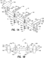
- FIGS. 1A-1C are views of an engine support system 10.
- the engine support system 10 includes an engine support 12 and two couplers 14A, 14B.
- the engine support 12 includes a frame mount 16, a first jack assembly 18A movably attached to the frame mount 16, and a second jack assembly 18B movably attached to the frame mount 16.
- the frame mount 16 includes an elongated body 100, a first arm 102A slidably mounted on the elongated body, generally proximate a first end of the elongated body 100, and a second arm 102B slidably mounted on the elongated body, generally proximate a second end of the elongated body 100 opposite the first end.
- the first arm 102A and the second arm 102B each includes an opening 106A and 106B, respectively, in which the elongated body 100 is received and is adapted to slide.
- the openings 106A and 106B may have a common axis A with the elongated body as seen in FIGS. 1A-1C .
- the elongated body 100 only includes one slidable arm, e.g., arm 102A, while the other arm, e.g., 102B, is fixed to the elongated body.
- the external shape of the elongated body 100 and the internal shape of the openings 106A and 106B have corresponding non-circular shapes (e.g., rectangular cross-section, square cross-section, etc.) to prevent relative rotation between the elongated body 100 and the first arm 102A and the second arm 102B.
- Such a configuration ensures vertical alignment of the first arm 102A, second arm 102B, first jack assembly 18A, and/or second jack assembly 18B. This relative alignment facilitates ease of use by an operator in mounting to the vehicle frame and engaging couplers 14A, 14B mounted to the underside of an engine block of the engine.
- the elongated body 100 and first and second arms 102A and 102B are ordinarily but not necessarily non-rotatable relative to each other.
- the external shape of the elongated body and the internal shapes of the first and second arms may, however, be circular and rotatable relative to each other.
- the first arm 102A is configured to releasably engage a first side (e.g., first rail) of a vehicle frame of the vehicle.
- the first arm 102A includes a first vertical portion 108A extending upward from the opening 106A defining one or more slots 109A.
- the first arm 102A further includes a first flange 110A outwardly extending from a top of the first vertical portion 108A.
- the first flange 110A is configured to engage the first rail of the vehicle frame.
- the first flange 110A includes a first edge 112A, which is ordinarily tapered (e.g., from a front to a back) to provide a maximum contact surface area when the first rail is angled relative to a center axis of the vehicle.
- a first clamping jaw 114A is removably attached to the first arm 102A.
- the first clamping jaw 114A applies a compressive force on the first rail.
- the first clamping jaw 114A includes a first bracket 116A and a first clamping bolt 118A ( FIG. 1C ).
- the first clamping jaw 114A includes the first bracket 116A, which is ordinarily horizontal, and a vertical portion 120A ( FIG. 1C ).
- the vertical portion 120A includes one or more threaded holes 124A (shown by dashed lines in FIG. 1C ) to receive fasteners 126A inserted through the slots 109A of the first arm 102A to attach the first clamping jaw 114A to the first arm 102A.
- the slots 109A of the first arm 102A allow for adjustment of vertical position of the first clamping jaw 114A relative to the first arm 102A to accommodate frame rails having flanges of varying thicknesses.
- the first bracket 116A includes a threaded hole 128A ( FIG. 1C ) to receive the first clamping bolt 118A ( FIG. 1C ) therein.
- the first clamping bolt 118A is configured to move relative to the first bracket 116A to clamp a portion of the first rail between the first flange 110A and the first clamping bolt 118A.
- horizontal and “vertical” in this context generally refers to a directional orientation relative to a vehicle or vehicle frame.
- “horizontal” (or “lateral”) and “vertical” may refer to a directional orientation of the engine support system 10 and/or components thereof (e.g., engine support 12, couplers 14A, 14B, etc.) when applied or being applied to the vehicle frame.
- “horizontal” (or “lateral”) may refer to an orientation side to side and/or front to back relative to a vehicle (e.g., vehicle frame), and “vertical” may refer to an orientation top to bottom relative to a vehicle (e.g., vehicle frame).
- the second arm 102B at the second end of the elongated body 100 is configured to releasably engage a second side (e.g., second rail) of the vehicle frame of the vehicle.
- a second clamping jaw 114B is removably attached to the second arm 102B.
- the second arm 102B and the second clamping jaw 114B can include similar features as the first arm 102A and the first clamping jaw 114A and, for purposes of the present discussion, are accordingly similarly numbered.
- the first jack assembly 18A includes a first collar 130A, a first threaded hole or cuff 132A, and a first jack rod 134A.
- the first collar 130A is slidably coupled to and positioned over the elongated body 100 and movable (e.g., laterally, horizontally, side to side, etc.) relative thereto along axis A through an opening 135A of the first collar.
- the opening 135A of the first collar 130A ordinarily but not necessarily includes a non-circular cross-section (e.g., rectangular cross-section, square cross-section, etc.) corresponding to an external shape of the elongated body 100 to prevent relative rotation between the first collar and the elongated body, however, the opening may be configured to permit rotation between the first collar and the elongated body. If the opening 135A of the first collar 130A and the elongated member 100 are non-rotatable relative to each other, this can facilitate ensuring vertical alignment of the first jack assembly 18A.
- the opening 135A of the first collar 130A can be U- or C-shaped, i.e. open at one end, as shown in FIGS. 1A-1C to extend around a horizontal top side and two vertical sides of the elongated body 100. In other aspects of the invention, the openings in the collars completely surround the elongated body.
- the first threaded cuff 132A may be in the form of a threaded hole in a leg of the first collar 130A as shown in FIGS. 1A-1C .
- the axis B1 of the first threaded cuff 132A is generally perpendicular to the axis A of the first collar 130A.
- the axis B1 of the first threaded cuff 132A is perpendicular to the axis A of the first collar 130A, however, it will be appreciated that it may be desirable to alter the angle of the first threaded cuff 132A from perpendicular for certain applications.
- the first jack rod 134A is positioned within the first threaded cuff 132A and vertically movable (e.g., translatable) relative thereto. In this way, the first jack rod 134A is coupled to the first collar 130A and configured to move vertically relative to the first collar 130A.
- the first jack rod 134A includes a threaded body 136A, a ball mount 138A at a top end of the threaded body 136A, and a hex cap 139A at a bottom end of the threaded body 136A.
- the hex cap 139A is configured to provide a feature for a tool to engage the first jack rod 134A to rotate the first jack rod 134A. Accordingly, rotation of the first jack rod 134 A rotates and vertically translates the first jack rod 134A relative to the first threaded cuff 132A and the first collar 130A.
- the first jack assembly 18A is configured to engage the first coupler 14A at a first side of the engine block of the vehicle, such as by insertion of the ball mount 138A into the first coupler 14A at an underside of the engine block of the vehicle.
- the first jack assembly 18A is configured to engage the first coupler 14A to support and/or lift the engine of the vehicle.
- the second jack assembly 18B includes a second collar 130B, a second threaded cuff 132B, and a second jack rod 134B.
- the second jack assembly 18B includes similar features as the first jack assembly 18A and is accordingly similarly numbered.
- the second collar 130B is configured to move (e.g., translate) along axis A of the elongated body 100 (e.g., independent of the first collar 130A).
- the axis B2 of the second threaded cuff 132B is generally perpendicular to the axis A of the second collar 130B again in the sense that it is ordinarily perpendicular, though there may be circumstances where it may be desirable to deviate from perpendicular.
- the second jack assembly 18B is configured to engage the second coupler 14 at a second side of the engine block of the vehicle, such as by insertion of the ball mount 138B into the second coupler 14B at an underside of the engine block of the vehicle.
- the second jack assembly 18B is configured to engage the second coupler 14B to support and/or lift the engine of the vehicle.
- the first coupler 14A is configured to removably attach to the underside of the engine block of the vehicle.
- the first coupler 14A includes a receptacle 140A fixedly attached to a plate 142A with a plurality of through holes 144A defined in the plate 142A.
- the plurality of through holes 144A are configured to accommodate different types of engine blocks which may have differently spaced holes.
- at least two of the plurality of through holes 144A of the plate 142A are configured to align with at least two threaded holes at the underside of the engine block of the vehicle.
- the receptacle 140A includes an opening 146A (shown by dashed lines in FIG. 1C ) configured to receive the ball mount 138A of the first jack rod 134A.
- the second coupler 14B includes similar features as the first coupler 14A and is accordingly similarly numbered.
- components of the engine support system 10 could be made of steel and fastened together using any of a variety of attachments (e.g., bolts, welding, etc.).
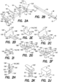
- FIG. 2A shows an engine support system 10' with several features that differ from the engine support system shown in FIG. 1A .
- the elongated body 100 may be the same elongated body as in FIG. 1A .
- the elongated body 100 shown in FIG. 2A (and 2B ) includes a series of pin holes 101 at ends of the elongated body to receive pins 103 for retaining the arms 102A' and 102B' in desired longitudinal positions along the elongated body.
- a suitable form of pin 103 has a ring at one end or is otherwise enlarged at one end to prevent the pin from passing entirely through the pin holes 101, and a hole (not shown) at an opposite end for receiving a cotter pin (not shown) to hold the pin in place in the pin hole.
- Pin holes and pins may also be provided in connection with the elongated body 100 of FIG. 1A .
- the openings 106A' and 106B' in the first and second arms 102A' and 102B', respectively, are rectangular with a vertical height in a longitudinal direction of the arms that is greater than a vertical height of the elongated body so that the axis of the elongated body 100 is parallel with but not necessarily common with the axis of the openings 106A' and 106B'.
- the elongated body 100 is square with a width WE and a height HE equal to the width as shown, for example, in FIG. 2B , the opening 106A' in the first arm 102A' ( FIGS.
- FIGS. 2C and 2F ) and the opening 106B' in the second arm 102B' may be rectangular as shown in FIGS. 2C, 2D, and 2F having a horizontal width HH (shown in FIG. 2C ) sufficiently larger than the width WE of the elongated body to permit sliding of the elongated body through the opening, and having a vertical height VH (shown in FIG. 2C ) larger than the horizontal width of the opening and larger than the vertical height HE of the elongated body so that the elongated body can be moved vertically up and down in the opening.
- HH shown in FIG. 2C
- VH vertical height
- the position of the elongated member relative to the arms 102A' and 102B' can be adjusted in height, such as by providing a spacer 105 ( FIG. 2J ) at a bottom of an opening, as shown for the arm 102B' in FIG. 2K , upon which the elongated member can rest.
- the elongated member 100 need not be rectangular or square in cross-section, and may be wider than taller, or taller than wider, and the openings 106A' and 106B' need not be rectangular or square in cross-section, and may be wider than taller, or taller than wider, however, it may nonetheless be desirable to provide a configuration wherein the openings 106A' and 106B' are vertically longer than the elongated member 100 is in its vertical direction, whatever the shape of the openings and the elongated member, as such a configuration can facilitate avoiding interference with components such as suspension components on the vehicle that otherwise might be contacted by the elongated member 100.
- the angle at which the engine is mounted relative to the crankshaft may result in the bottom of the engine lying closer to suspension components than in other models, necessitating raising of the elongated member to avoid interference with the suspension components.
- the first and second arms 102A' and 102B' can otherwise be substantially the same as the first and second arms 102A and 102B described in connection with FIGS. 1A-1C .
- the openings 106A' and 106B' of the first arm 102A' and the second arm 102B' are provided in a first vertical portion 108A' and a second vertical portion 108B' of the first arm and the second arm, respectively.
- Slots 109A' and 109B' are provided in the first vertical portion 108A' and the second vertical portion 108B', respectively, for attaching vertical portions 120A and 120B of clamping jaws 114A ( FIG. 2F ) and 114B ( FIG. 2G ).
- the clamping jaws 114A and 114B can be identical, and, as seen in FIG. 2E , can include holes 124A (and identical holes 124B in the clamping jaw 114B as seen in FIG. 2G ) for securing the vertical portions 120A and 120B of the clamping jaws to the first and second vertical portions 108A' and 108B' of their respective arms by suitable fasteners such as bolts and nuts, or fasteners 126 that can mate with internal threads in the holes 124A.
- suitable fasteners such as bolts and nuts, or fasteners 126 that can mate with internal threads in the holes 124A.
- the holes can be unthreaded and the clamping jaws may be attached to the arms by bolts that extend through the slots in the arms and into the unthreaded holes and that mate with bolts.
- the first arm 102A' and the second arm 102B' can also include a first flange 110A' and a second flange 110B' extending outwardly, generally perpendicularly, from the tops of the first vertical portion 108A' and the second vertical portion 108B', respectively.
- the first flange 110A' and the second flange 110B' are configured to engage the first and second rails of the vehicle frame.
- the first flange 110A' includes a first edge 112A' and the second flange 110B' includes a second edge 112B'. As seen, for example, in FIG.
- the first edge 112A' and the second edge 112B' are ordinarily tapered (e.g., from a front to a back) to provide a maximum contact surface area with the first and second rails, which are often angled relative to a center axis of the vehicle.
- the slots 109A' of the first arm 102A' and the slots 109B' of the second arm 102B' are ordinarily elongated to allow for adjustment of vertical position of the first clamping jaw 114A' relative to the first arm 102A' and the second clamping jaw 114B relative to the second arm 102B' to accommodate frame rails having flanges of varying thicknesses.
- the first clamping jaw 114A and the second clamping jaw 114B include a first bracket 116A and a second bracket 116B, respectively, which are ordinarily horizontal in the engine support system 10' as shown in FIG. 2A , and the first vertical portion 120A and the second vertical portion, respectively.
- the vertical portion 120A includes the one or more holes 124A to receive fasteners for attaching the first clamping jaw to the first arm.
- the first bracket 116A and the second bracket 116B each includes a threaded hole 128A and 128B, respectively, to receive a first clamping bolt 118A and a second clamping bolt 118B, respectively, therein.
- the first clamping bolt 118A and the second clamping bolt 118B are configured to move relative to the first bracket 116A and the second bracket 116B, respectively, so that a portion of the first rail is clamped between the first flange 110A and the first clamping bolt 118A and a portion of the second rail is clamped between the second flange 110B and the second clamping bolt 118B.
- FIG. 2A shows the engine support system 10' with identical first and second jack assemblies 18A' and 18B'.
- the jack assembly 18A' includes a first collar 130A', a first cuff 132A' with a threaded hole 133A', and a first jack rod 134A'.
- the first collar 130A' is slidably coupled to and positioned around the elongated body 100, which extends through an opening 135A' in the first collar.
- the first collar 130A' is movable in the direction of the longitudinal axis of the elongated body.
- the opening 135A' of the first collar 130A' ordinarily but not necessarily includes a non-circular cross-section (e.g., rectangular cross-section, square cross-section, etc.) corresponding to an external shape of the elongated body 100 to prevent relative rotation between the first collar and the elongated body, however, the opening may be configured to permit rotation between the first collar and the elongated body. If the opening 135A' of the first collar 130A' and the elongated member 100 are non-rotatable relative to each other, this can facilitate ensuring vertical alignment of the jack assembly 18A.
- a non-circular cross-section e.g., rectangular cross-section, square cross-section, etc.
- the first threaded cuff 132A' may be attached to or integral with an outer side surface of a portion of the first collar 130A'.
- the axis of the threaded hole 133A' is generally perpendicular to the central axis of the hole 135A' of the first collar 130A'. Ordinarily, the axis of the threaded hole 133A' is perpendicular to the central axis of the first collar, however, it will be appreciated that it may be desirable to alter the angle of the threaded hole from perpendicular for certain applications.
- first threaded cuff 132A' and its threaded hole 133A' are shown as centered along an axis of the opening 135' of the first collar 130A'in FIGS. 2A and 2H , as seen with reference to FIGS. 3A-3E , a first threaded cuff 132A" and its threaded hole may be offset from a center of the first collar 130A" along the axis of the opening of the first collar.
- the threaded hole of the first threaded cuff may be offset from the center of the first collar along the axis A. Offsetting the location of the cuff and the threaded hole may provide more variability for mounting to the elongated body 100 and for accommodating different types of engines and/or vehicles.
- the first jack rod 134A' is positioned within the threaded hole 133A' of the first threaded cuff 132A' and vertically movable (e.g., translatable) relative thereto. In this way, the first jack rod 134A' is coupled to the first collar 130A' and configured to move vertically relative to the first collar 130A'. Like the first jack rod 134A of FIGS. 1A-1C , the first jack rod 134A' of FIG.
- the first jack assembly 18A' is configured to engage a first coupler 14A' ( FIG. 2I ) at a first side of the engine block of the vehicle, such as by insertion of the ball mount 138A' into the first coupler 14A' at an underside of the engine block of the vehicle.
- the first jack assembly 18A is configured to engage the first coupler 14A to support and/or lift the engine of the vehicle.
- the first coupler 14A of FIGS. 2A and 2I is ordinarily identical to the second coupler 14B of FIG. 2A , and is the same as the first and second couplers of FIGS. 1A-1C .
- the first coupler 14 is configured to removably attach to the underside of the engine block of the vehicle.
- the first coupler 14A includes a receptacle 140A fixedly attached to a plate 142A with a plurality of through holes 144A in the plate 142A.
- the plurality of through holes 144A are configured so that some of the holes 144A can align with threaded holes that are provided on different types of engine blocks.
- the threaded holes on the engine blocks may be provided for attaching components of a vehicle to the engine, or specially provided for purposes of attaching a coupler of an engine support system according to the present invention.
- at least two of the plurality of through holes 144A of the plate 142A are configured to align with at least two threaded holes at the underside of an engine block of a given vehicle.
- the receptacle 140A includes an opening 146A configured to receive the ball mount 138A of the first jack rod 134A.
- the second coupler 14B includes similar features as the first coupler 14A.
- the spacer 105 such as is shown in FIG. 2J can be attached at the bottoms of the openings 106A' and 106B' of the arms 102A' and 102B', respectively, so that the elongated member 100 will rest on spacers instead of the bottoms of the openings. Such an arrangement can be useful for, among other things, avoiding interference between the elongated member 100 and structures on a vehicle such as suspension components.
- FIG. 2K shows a form of spacer 105 attached at the bottom of the opening 106B' of an arm 102B' (the same arrangement applies for spacers at the bottom of openings 106A' of arms 102A').
- This spacer 105 includes a notch 107 for receiving an edge of the arm 102B' at the bottom of the opening 106B'.
- the spacer 105 further includes holes 109 in legs 111 of the spacer defining the notch. When the spacer 105 is seated on the edge of the arm 102B' at the bottom of the opening 106B', the holes 109 in the legs 111 of the spacer align with a hole 113B' ( FIG. 2G ) in the vertical portion 108B' of the arm.
- the spacer 105 can be secured to the arm 102B' such as by a pin 103 that is received in the holes 109 in the legs 111 of the spacer and the hole 113B' in the vertical portion 108B' of the arm and locked in place with a cotter pin.
- FIGS. 3A-3E show an engine support system 10" that is the same as the engine support system 10 of FIGS. 1A-1C except for jack assemblies 18A" and 18B" with a first collar 130A" and a second collar 130B", respectively, that differs from the first collar 130A and the second collar 130B of the jack assemblies 18A and 18B of the engine support system of FIGS. 1A-1C in that, like the collars of the jack assemblies 18A' and 18B' of FIG. 2A , the first collar 130A" and the second collar 130B" completely surround the elongated body 100, whereas the first collar 130A and the second collar 130B are C- or U-shaped, i.e. open on one side.
- FIGS. 3A-3E are views illustrating use of an engine support system 10" like that of FIGS. 1A-1C to support and/or lift an engine 200 of the vehicle 202.
- FIG. 2A is a side view of the engine support system 10" illustrating jack rods 134A, 134B of jack assemblies 18A", 18B" of the engine support system 10" aligned with and disengaged from the couplers 14A, 14B mounted to the engine 200. It will be appreciated that the description of the use of the engine support system 10" in FIGS. 3A-3E applies as well to the engine support system 10 of FIGS. 1A-1C .
- the engine support system 10" (or 10) can be used by removing the oil drip pan from the underside 204 of the engine block 206.
- the couplers 14A, 14B are then mounted to the threaded holes 208 (see e.g., FIG. 3C ) at the underside 204 of the engine block 206 that were used for attachment of the oil drip pan.
- the first arm 102A is moved along elongated body 100 so that the first flange 110A rests on the first rail 210A of a vehicle frame 212 of the vehicle 202, and the second flange 110B rests on the second rail 210B of the vehicle frame 212 of the vehicle 202 with the elongated body 100 positioned beneath the engine 200.
- the second arm 102B is movable relative to the elongated body 100, the second arm may also be moved along the elongated by so that the second flange 110B rests on the second rail 210B of the vehicle frame 212 of the vehicle 202.
- the frame mount 16 is positioned along a length of the vehicle 202 so that the horizontal path of the jack rods 134A, 134B is aligned with the couplers 14A, 14B along the length of the vehicle 202.
- the first bracket 116A is mounted to the first vertical portion 108A of the first arm 102A and moved vertically toward the first rail 210A.
- the first clamping bolt 118A is then moved vertically to apply or increase the clamping pressure applied to the first rail 210A (i.e., between the first flange 110A and the first clamping bolt 118A).
- the second bracket 116B is mounted to the second vertical portion 108B of the second arm 102B and moved vertically toward the second rail 210B.
- the second clamping bolt 118B is then moved vertically to apply or increase the clamping pressure applied to the second rail 210B (i.e., between the second flange 110B and the second clamping bolt 118B).
- the first collar 130A" of the first jack assembly 18A" is slid horizontally along the elongated body 100 to align the first jack rod 134A with the first opening 146A of the first receptacle 140A of the first coupler 14A.
- the second collar 130B" of the second jack assembly 18B” is slid horizontally along the elongated body 100 to align the second jack rod 134B" with the second opening 146B of the second receptacle 140B of the second coupler 14B.
- the offset of the jack rods 134A, 134B relative to the collars 130A", 130B” means that the collars 130A", 130B" could be disassembled from the elongated body 100 and reassembled so that the relative position of the first jack assembly 18A" is switched with that of the second jack assembly 18B".
- the jack rods 134A, 134B are positioned farther apart, and in a second orientation the jack rods 134A, 134B are positioned closer to one another, even though the respective collars 130A", 130B" are in the same position on the elongated body 100.
- jack rods 134A, 134B on outer side surfaces of the collars 130A", 130B" provides an additional orientation for mounting.
- Such asymmetries increase the modularity of the engine support system 10 to accommodate different types of engines and/or different types of vehicles.
- the first flange 110A includes a first edge 112A, which is tapered (e.g., from a front to a back) to increase a contact surface area with the first rail 210A
- the second flange 110B includes a second edge 112B, which is tapered (e.g., from a front to a back) to provide a maximum contact surface area with the second rail 210B.
- the spherical shape of the ball mounts 138A, 138B and the oversize of the opening 146A, 146B (e.g., openings 146A, 146B are larger in diameter than the ball mounts 138A, 138B) accommodate rotational variance of the engine 200 (e.g., angled mount of the engine 200 relative to the vehicle frame 212). Further, the angled mount accounts for relative angling of the engine 200 as the jack rods 134A, 134B are iteratively rotated to support and/or lift the engine 200 relative to the vehicle frame 212. For example, to lift the engine level, the first jack rod 134A travels vertically and lifts a first side of the engine 200.
- the first jack rod 134A then travels further vertically to lift the first side of the engine 200 higher than the second side. Then the second jack rod 134B travels vertically to lift the second side of the engine 200 higher than the first side. This process repeats until the engine 200 is supported and/or lifted to a desired height relative to the vehicle frame 212.
- the jack assemblies 18A", 18B" are configured to support the engine block 206 of the vehicle 202 relative to the vehicle frame 212 by vertical movement of the ball mounts 138A, 138B into the couplers 14A, 14B and relative to the frame mount 16 engaged with the vehicle frame 212.
- the jack assemblies 18A", 18B” are configured to lift the engine block 206 of the vehicle 202 relative to the frame 212 of the vehicle 202 by vertical movement of the ball mounts 138A, 138B in the couplers 14A, 14B and relative to the frame mount 16 engaged with the vehicle frame 212.
- the engine 200 can be serviced (e.g., removing fly wheel housing, removing transmission, etc.).
- FIG. 4A is a cross-sectional side view of an alternative embodiment of the coupler 14A or 14B of FIGS. 1A-1C , 2A , 2I , and 3A-3E .
- the coupler 300 of FIG. 4A includes a receptacle 302 with an opening 304 at a bottom to receive the ball mounts of the jack rods of the jack assemblies.
- the receptacle 302 further includes a through hole 306 and a countersink 308 to receive a fastener 310 therein, such that the head 312 of the fastener 310 is positioned in the countersink 308.
- FIG. 4B is a perspective view of the engine support system 10" of FIGS. 3A-3E engaged with the coupler 300 of FIG. 4A .
- the ball mount 138B of the second jack rod 134B of the second jack assembly 18B" is inserted into the coupler 300.
- the opening in the arm through which the elongated member extends may be the same size as or, as shown in phantom, vertically higher than the elongated member.
- the coupler 300 is universal and only requires one threaded hole 208 in the engine block 206.
- the first coupler includes a receptacle defining a through hole 306 (see FIG. 4A ) configured to receive a fastener 310 (see FIG. 4A ) to removably attach the first coupler 300 to a single threaded hole 208 at the underside 204 of the engine block 206 of the vehicle 202.
- the coupler 300 increases the flexibility and modularity of mounting.
- FIG. 5 is a flowchart 400 illustrating a method of supporting an engine 200 of a vehicle 202 using the engine support systems of FIGS. 1A-1C , 2A , 3A-3E , or 4A-4B .
- Step 402 includes suspending a frame mount 416 of an engine support system 10 across a frame 212 of a vehicle 202 beneath an engine block 206 of the vehicle 202 by moving a first arm 102A attached to a first end of an elongated body 100 relative to a second arm 102B attached to a second end of the elongated body 100 to an engaged orientation.
- the method further includes attaching a first clamping jaw 114A to the first arm 102A to position a portion of a first rail 210A of the frame 212 of the vehicle 202 between a first flange 110A of the first arm 102A and a first bracket 116A of the first clamping jaw 114A, and rotating a first clamping bolt 118A in a first threaded hole 128A of the first bracket 116A of the first clamping jaw 114A to clamp the portion of the first rail 210A of the frame 212 of the vehicle 202 between the first flange 110A and the first clamping bolt 118A.
- the method further includes horizontally sliding a second collar 130B of a second jack assembly 18B of the engine support system 10 along the elongated body 100 to align a ball mount 138B of a second jack rod 134B of the second jack assembly 18B with a second coupler 14B at the underside 204 of the engine block 206 of the vehicle 202.
- the method further includes engaging the second jack assembly 18B with the engine block 206 by vertically moving the second jack rod 134B of the second jack assembly 18B to insert the ball mount 138B of the second jack assembly 18B into the second coupler 14B of the engine block 206.
- the method further includes supporting the engine 200 of the vehicle 202 relative to the frame 212 of the vehicle 202 by vertically moving the second jack rod 134B of the second jack assembly 18B to insert the ball mount 138B of the second jack rod 134B of the second jack assembly 18B into the second coupler 14B at the underside 204 of the engine block 206.
- Step 404 includes horizontally sliding a first collar 130A of a first jack assembly 18A of the engine support system 10 along the elongated body 100 to align a ball mount 138A of a first jack rod 134A of the first jack assembly 18A with a first coupler 14A at an underside 204 of the engine block 206 of the vehicle 202.
- the method further includes attaching the first coupler 14A to the underside 204 of the engine block 206 of the vehicle 202.
- Step 406 includes supporting an engine 200 of the vehicle 202 relative to the frame 212 of the vehicle 202 by vertically moving the first jack rod 134A of the first jack assembly 18A to insert the ball mount 138A of the first jack rod 134A of the first jack assembly 18A into the first coupler 14A at the underside 204 of the engine block 206.
- Step 408 includes lifting an engine 200 of the vehicle 202 relative to the frame 212 of the vehicle 202 by continued vertical movement of the first jack rod 134A of the first jack assembly 18A.
- FIGS. 6A-6E illustrate a method of supporting an engine 200E of a vehicle using an engine support system 10' and components as shown in FIG. 2A-2K .
- the first and second arms 102A' and 102B' are positioned with undersides of their flanges 110A' and 110B' (shown in phantom) on top of left and right rails 210L and 210R, with wide ends of the flanges pointed toward the front 200F of the engine 200E.
- the first and second clamping jaws 114A and 114B are loosely attached to the arms 102A' and 102B', respectively, with, as seen in FIG.
- the elongated member 100 is slid into the openings 135A' and 135B' of the first and second collars 130A' and 130B', respectively, of the first and second jack assemblies 18A' and 18B', respectively, usually prior to threading the jack rods 134A' and 134B' (seen in FIG. 6E ) into the threaded holes of the cuffs 132A' and 132B'.
- an end of the elongated member is slid into one of the openings of one of the first and second arms.
- FIG. 6C the end of the elongated member 100 is shown first slid into the opening 106A' of the first arm 102A', however, the end of the elongated member might, alternatively, be first slid into the opening 106B' of the second arm 102B'.
- a spacer 105 is attached (as shown in FIG. 2K ) to the bottom edges each of the openings 106A' and 106B' of the first and second arms 102A' and 102B', respectively, to raise the position of the elongated member 100 relative to the first and second arms to clear the interfering component.
- the spacers 105 are secured to the arms 102A' and 102B' with pins 103.
- FIG. 6E illustrates an engine support system 10' with spacers 105.
- the free end of the elongated member 100 is then slid into the opening of the other one of the first and second arms.
- the end of the elongated member 100 is shown slid into the opening 106B' of the second arm 102B' after having been first slid into the opening 106A' of the first arm 102A'.
- first and second arms 102A' and 102B' are properly positioned along the rails 200L and 200R relative to the engine 200E at this point, then the first and second arms are tightly fastened to the first and second clamping jaws 114A and 114B with the fasteners 126 and are secured in place along the length of the elongated member 100 by pins 103 extending through pin holes 101 in the elongated member on opposite sides of the first and second arms.
- the jack rods 134A' and 134B' are threaded into the threaded holes of the cuffs 132A' and 132B', such as by engaging the hex caps 139A' and 139B' with a tool, so that the ball mounts 138A' and 138B' extend above tops of the cuffs.
- the ball mounts 138A' and 138B' of the jack rods 134A' and 134B', respectively, are inserted into the openings 146A and 146B of the couplers 14A (mostly obscured by engine component in FIG.
- holes 144A and 144B in the plates 142A and 144B are aligned with holes in the engine, such as holes for an oil pan.
- the positions of the first and second jack assemblies 18A' and 18B' along the elongated member 100 may be adjusted and, if necessary, the positions of the first and second arms 102A' and 102B' may be adjusted along the length of the elongated member 100 and along the lengths of the left and right rails 210L and 210R.
- the first and second jack assemblies 18A' and 18B' and the first and second arms 102A' and 102B' are positioned as desired and, if not already done as shown in FIG. 6D , the first and second arms 102A' and 102B' are tightly fastened to the first and second clamping jaws 114A and 114B with the fasteners 126 and are secured in place along the length of the elongated member 100 by pins 103 extending through pin holes 101 in the elongated member on opposite sides of the first and second arms.
- a first clamping bolt 118A is screwed into the threaded hole 128A of the first bracket 116A of the first clamping jaw 114A and a second clamping bolt 118B is screwed into the threaded hole 128B of the second bracket 116B of the second clamping jaw 114B to clamp the left rail 210L between the first arm 102A' and the first clamping jaw 114A and the right rail 210R between the second arm 102B' and the second clamping jaw 114B.
- the jack rods 134A' and 134B' are further threaded into the threaded holes of the cuffs 132A' and 132B' so that the plates 142A and 142B of the couplers 14A and 14B at the tops of the jack rods touch the engine and the holes 144A and 144B in the plates are aligned with the holes in the engine 200E.
- the plates 142A and 142B of the couplers 14A and 14B are attached to the engine 200 by screws 200S that extend through the holes 144A and 144B in the plates and mate with threads in the holes in the engine 200E.
- the jack rods 134A' and 134B' are then further threaded into the threaded holes of the cuffs 132A' and 132B' so that the engine 200E is supported or lifted relative to the vehicle frame by the engine support system 10'.
- An engine support system for a vehicle comprising: a frame mount comprising: an elongated body; a first arm slidably mounted on the elongated body and configured to releasably engage a first side of a frame of a vehicle; and a second arm mounted on the elongated body and configured to releasably engage a second side of the vehicle frame; a first coupler configured to attach to an engine of the vehicle; and a first jack assembly, comprising: a first collar slidably mounted on the elongated body and configured to move in a longitudinal direction of the elongated body; and a first jack rod coupled to the first collar and configured to move generally perpendicular to the longitudinal direction of the elongated body, the first jack rod comprising a body and a ball mount at an end of the body, the ball mount configured to insert into the first coupler at an underside of an engine block of the vehicle.
- Example 2 The engine support system of example 1, wherein the first coupler is configured to removably attach to the underside of the engine block of the vehicle.
- Example 3 The engine support system of example 1, wherein the first coupler is configured to removably attach to threaded holes configured to mount an oil drip pan to the underside of the engine block of the vehicle.
- Example 4 The engine support system of any of examples 1-2, wherein the first coupler includes a receptacle defining a through hole configured to receive a fastener to removably attach the first coupler to a single threaded hole at the underside of the engine block of the vehicle.
- Example 5 The engine support system of any of examples 1-2, wherein the first coupler includes a receptacle fixedly attached to a plate with a plurality of through holes, at least two of the plurality of through holes configured to align with at least two threaded holes at the underside of the engine block of the vehicle.
- Example 6 The engine support system of any of examples 1-4, wherein the first arm comprises an opening having a non-circular cross-section, the elongated body having a corresponding non-circular cross-section and being received in and non-rotatable relative to the opening.
- Example 7 The engine support system of any of examples 1-5, wherein the first arm comprises an opening through which the elongated body is adapted to slide.
- Example 8 The engine support system of any of examples 1-7, wherein the opening has a vertical height in a longitudinal direction of the first arm that is greater than a vertical height of the elongated body.
- Example 9 The engine support system of any of examples 1-8, further comprising a spacer attachable to the first arm at a bottom of the opening.
- Example 10 The engine support system of example 1, wherein the elongated body has a non-circular cross-section and the first collar has non-circular opening, the elongated body being received in and non-rotatable relative to the first collar.
- Example 11 The engine support system of any of examples 1-8, wherein the first arm comprises a first flange configured to engage a first upper surface of a first rail of the vehicle frame and the second arm comprises a second flange configured to engage a second upper surface of a second rail of the vehicle frame.
- Example 12 The engine support system of any of examples 1-11, wherein a first edge of the first flange of the first arm is tapered to increase a contact surface area with the first rail angled relative to a center axis of the vehicle; and wherein a second edge of the second flange of the second arm is tapered to increase a contact surface area with the second rail angled relative to the center axis of the vehicle.
- Example 13 The engine support system of any of examples 1-12, wherein the frame mount further comprises: a first clamping jaw removably attached to the first arm, the first clamping jaw comprising a first bracket and a first clamping bolt, the first bracket defining a first threaded hole, the first clamping bolt positioned in the first threaded hole and configured to move relative thereto to clamp a portion of the first rail between the first flange and the first clamping bolt; and a second clamping jaw removably attached to the second arm, the second clamping jaw comprising a second bracket and a second clamping bolt, the second bracket defining a second threaded hole, the second clamping bolt positioned in the second threaded hole and configured to move relative thereto to clamp a portion of the second rail between the second flange and the second clamping bolt.
- Example 14 The engine support system of claim any of examples 1-13, wherein the first jack assembly is configured to lift the engine block of the vehicle relative to the vehicle frame by vertical movement of the first jack rod relative to the frame mount engaged with the vehicle frame with the ball mount in the first coupler.
- Example 15 The engine support system of example 1, wherein the body of the first jack rod is threaded.
- Example 16 The engine support system of example 15, wherein the first jack assembly further comprises a first threaded cuff attached to the first collar, the first jack rod positioned within the threaded cuff.
- Example 17 The engine support system of example 15, wherein the first jack assembly further comprises a first threaded cuff fixedly attached to an outer surface of the first collar and offset from a center of the first collar along a center axis of the first collar.
- Example 18 The engine support system of claim any of examples 1-17, wherein the first collar is U-shaped.
- Example 19 The engine support system of any of examples 1-18, wherein the second arm is slidably mounted on the elongated body.
- Example 20 The engine support system of example 19, wherein the second arm comprises an opening having a non-circular cross-section, the elongated body having a corresponding non-circular cross-section and being received in and non-rotatable relative to the opening.
- Example 21 The engine support system of example 1, wherein the first jack assembly is configured to engage the first coupler at a first side of the engine block of the vehicle; wherein the engine support system further comprises a second jack assembly configured to engage a second coupler at a second side of the engine block of the vehicle, comprising: a second collar slidably mounted on the elongated body and configured to move in a longitudinal direction of the elongated body; and a second jack rod threadably coupled to the second collar and configured to move generally perpendicular to the longitudinal direction of the elongated body, the second jack rod comprising a second body and a second ball mount at an end of the second body, the second ball mount configured to insert into the second coupler at the underside of the engine block of the vehicle.
- a second jack assembly configured to engage a second coupler at a second side of the engine block of the vehicle, comprising: a second collar slidably mounted on the elongated body and configured to move in a longitudinal direction of the elong
- Example 22 The engine support system of any of examples 1-21, wherein the first arm, the second arm, and the first collar are removably mounted on the elongated body.
- Example 23 A method of supporting an engine of a vehicle, comprising: suspending a frame mount of an engine support system across a frame of a vehicle beneath an engine block of the vehicle by moving a first arm slidably attached to an elongated body relative to a second arm attached to the elongated body to an engaged orientation; sliding a first collar of a first jack assembly of the engine support system in a longitudinal direction of the elongated body to align a ball mount of a first jack rod of the first jack assembly with a first coupler at an underside of the engine block of the vehicle; and supporting an engine of the vehicle relative to the vehicle frame by moving the first jack rod of the first jack assembly generally perpendicular to the longitudinal direction of the elongated body to insert the ball mount of the first jack rod of the first jack assembly into the first coupler at the underside of the engine block.
- Example 24 The method of example 23, further comprising lifting an engine of the vehicle relative to the vehicle frame by continued movement of the first jack rod of the first jack assembly.
- Example 25 The method of example 23, further comprising attaching the first coupler to the underside of the engine block of the vehicle.
- Example 26 The method of example 23, further comprising: attaching a first clamping jaw to the first arm to position a portion of a first rail of the vehicle frame between a flange of the first arm and a first bracket of the first clamping jaw; and rotating a first clamping bolt in a first threaded hole of the first bracket of the first clamping jaw to clamp the portion of the first rail of the vehicle frame between the first flange and the first clamping bolt.
- Example 27 The method of example 23, further comprising: sliding a second collar of a second jack assembly of the engine support system in the longitudinal direction of the elongated body to align a ball mount of a second jack rod of the second jack assembly with a second coupler at the underside of the engine block of the vehicle; and supporting the engine of the vehicle relative to the vehicle frame by vertically moving the second jack rod of the second jack assembly to insert the ball mount of the second jack rod of the second jack assembly into the second coupler at the underside of the engine block.
- Example 28 The method of example 23, wherein suspending the frame mount of the engine support system across the frame of the vehicle beneath the engine block of the vehicle further comprises moving the second arm relative to the elongated body to an engaged orientation.
- Example 29 The method of example 23, comprising sliding the elongated body relative to the first arm by moving the elongated body through an opening in the first arm.
- Example 30 The method of example 29, wherein the opening has a vertical height in a longitudinal direction of the first arm that is greater than a vertical height of the elongated body, the method comprising supporting the elongated body on a bottom of the opening.
- Example 31 The method of example 30, comprising changing a vertical height of the opening by attaching a spacer to the first arm at a bottom of the opening, the elongated body being supported on the bottom of the opening on top of the spacer.
Landscapes
- Engineering & Computer Science (AREA)
- Mechanical Engineering (AREA)
- Chemical & Material Sciences (AREA)
- Combustion & Propulsion (AREA)
- Transportation (AREA)
- Life Sciences & Earth Sciences (AREA)
- Geology (AREA)
- Structural Engineering (AREA)
- Vehicle Cleaning, Maintenance, Repair, Refitting, And Outriggers (AREA)
Abstract
a frame mount comprising:
an elongated body (100);
a first arm (102A, 102A') slidably mounted on the elongated body (100) and configured to releasably engage a first side of a frame of a vehicle; and
a second arm (102B, 102B') mounted on the elongated body (100) and configured to releasably engage a second side of the vehicle frame;
a first coupler (14A, 300) configured to attach to an engine of the vehicle; and
a first jack assembly (18A, 18A', 18A"), comprising:
a first collar (130A, 130A', 130A") slidably mounted on the elongated body (100) and configured to move in a longitudinal direction of the elongated body (100); and
a first jack rod (134A, 134A') coupled to the first collar (130A, 130A', 130A") and configured to move generally perpendicular to the longitudinal direction of the elongated body (100), the first jack rod (134A, 134A') comprising a body (136A, 136A') and a ball mount (138A, 138A') at an end of the body (136A, 136A'), the ball mount (138A, 138A') configured to insert into the first coupler (14A, 300) at an underside of an engine block of the vehicle.
Description
- The disclosure relates generally to engine supports. In particular aspects, the disclosure relates to a frame mounted engine support system and method including a frame mounted engine support and at least one engine mounted coupler.
- Vehicle engines, such as for trucking vehicles, occasionally require servicing and/or tuning to repair, maintain, or improve engine performance. Operators may require access to different portions of the engine depending on the type of work to be performed. Accordingly, operators may need a mechanical device to support and/or elevate the engine relative to a frame of a vehicle to provide sufficient access to the desired portion of the engine.
- According to an aspect of the disclosure, an engine support system for a vehicle comprises a frame mount comprising an elongated body, a first arm slidably mounted on the elongated body and configured to releasably engage a first side of a frame of a vehicle, and a second arm mounted on the elongated body and configured to releasably engage a second side of the vehicle frame. The engine support system further comprises a first coupler configured to attach to an engine of the vehicle. The engine support system further comprises a first jack assembly, comprising a first collar slidably mounted on the elongated body and configured to move in a longitudinal direction of the elongated body, and a first jack rod coupled to the first collar and configured to move generally perpendicular to the longitudinal direction of the elongated body, the first jack rod comprising a body and a ball mount at an end of the body, the ball mount configured to insert into the first coupler at an underside of an engine block of the vehicle.
- In some examples of the engine support system the first coupler is configured to removably attach to the underside of the engine block of the vehicle.
- In some examples of the engine support system the first coupler is configured to removably attach to threaded holes configured to mount an oil drip pan to the underside of the engine block of the vehicle.
- In some examples of the engine support system the first coupler includes a receptacle defining a through hole configured to receive a fastener to removably attach the first coupler to a single threaded hole at the underside of the engine block of the vehicle.
- In some examples of the engine support system the first coupler includes a receptacle fixedly attached to a plate with a plurality of through holes, at least two of the plurality of through holes configured to align with at least two threaded holes at the underside of the engine block of the vehicle.
- In some examples of the engine support system the first arm comprises an opening having a non-circular cross-section, the elongated body having a corresponding non-circular cross-section and being received in and non-rotatable relative to the opening.
- In some examples of the engine support system the first arm comprises an opening through which the elongated body is adapted to slide.
- In some examples of the engine support system the opening has a vertical height in a longitudinal direction of the first arm that is greater than a vertical height of the elongated body.
- In some examples of the engine support system a spacer is attachable to the first arm at a bottom of the opening.
- In some examples of the engine support system the elongated body has a non-circular cross-section and the first collar has non-circular opening, the elongated body being received in and non-rotatable relative to the first collar.
- In some examples of the engine support system the first arm comprises a first flange configured to engage a first upper surface of a first rail of the vehicle frame and the second arm comprises a second flange configured to engage a second upper surface of a second rail of the vehicle frame.
- In some examples of the engine support system the first coupler a first edge of the first flange of the first arm is tapered to increase a contact surface area with the first rail angled relative to a center axis of the vehicle, and a second edge of the second flange of the second arm is tapered to increase a contact surface area with the second rail angled relative to the center axis of the vehicle.
- In some examples of the engine support system the frame mount further comprises a first clamping jaw removably attached to the first arm, the first clamping jaw comprising a first bracket and a first clamping bolt, the first bracket defining a first threaded hole, the first clamping bolt positioned in the first threaded hole and configured to move relative thereto to clamp a portion of the first rail between the first flange and the first clamping bolt, and a second clamping jaw removably attached to the second arm, the second clamping jaw comprising a second bracket and a second clamping bolt, the second bracket defining a second threaded hole, the second clamping bolt positioned in the second threaded hole and configured to move relative thereto to clamp a portion of the second rail between the second flange and the second clamping bolt.
- In some examples of the engine support system the first jack assembly is configured to lift the engine block of the vehicle relative to the vehicle frame by vertical movement of the jack rod relative to the frame mount engaged with the vehicle frame with the ball mount in the first coupler.
- In some examples of the engine support system the body of the first jack rod is threaded.
- In some examples of the engine support system the first jack assembly further comprises a first threaded cuff attached to the first collar, the first jack rod positioned within the threaded cuff.
- In some examples of the engine support system the first jack assembly further comprises a first threaded cuff fixedly attached to an outer surface of the first collar and offset from a center of the first collar along a center axis of the first collar.
- In some examples of the engine support system the first collar is C- or U-shaped.
- In some examples of the engine support system the second arm is slidably mounted on the elongated body.
- In some examples of the engine support system the second arm comprises an opening having a non-circular cross-section, the elongated body having a corresponding non-circular cross-section and being received in and non-rotatable relative to the opening.
- In some examples of the engine support system the first coupler the first jack assembly is configured to engage the first coupler at a first side of the engine block of the vehicle, and the engine support system further comprises a second jack assembly configured to engage a second coupler at a second side of the engine block of the vehicle comprising a second collar slidably mounted on the elongated body and configured to move in a longitudinal direction of the elongated body, and a second jack rod threadably coupled to the second collar and configured to move generally perpendicular to the longitudinal direction of the elongated body, the second jack rod comprising a second body and a second ball mount at an end of the second body, the second ball mount configured to insert into the second coupler at the underside of the engine block of the vehicle.
- In some examples of the engine support system the first arm, the second arm, and the first collar are removably mounted on the elongated body.
- According to another aspect of the disclosure, a method of supporting an engine of a vehicle comprises suspending a frame mount of an engine support system across a frame of a vehicle beneath an engine block of the vehicle by moving a first arm slidably attached to an elongated body relative to a second arm attached to the elongated body to an engaged orientation, sliding a first collar of a first jack assembly of the engine support system in a longitudinal direction of the elongated body to align a ball mount of a first jack rod of the first jack assembly with a first coupler at an underside of the engine block of the vehicle, and supporting an engine of the vehicle relative to the vehicle frame by moving the first jack rod of the first jack assembly generally perpendicular to the longitudinal direction of the elongated body to insert the ball mount of the first jack rod of the first jack assembly into the first coupler at the underside of the engine block.
- In some examples, the method further comprises lifting an engine of the vehicle relative to the vehicle frame by continued movement of the first jack rod of the first jack assembly.
- In some examples, the method further comprises attaching the first coupler to the underside of the engine block of the vehicle.
- In some examples, the method further comprises attaching a first clamping jaw to the first arm to position a portion of a first rail of the vehicle frame between a flange of the first arm and a first bracket of the first clamping jaw, and rotating a first clamping bolt in a first threaded hole of the first bracket of the first clamping jaw to clamp the portion of the first rail of the vehicle frame between the first flange and the first clamping bolt.
- In some examples, the method further comprises sliding a second collar of a second jack assembly of the engine support system in the longitudinal direction of the elongated body to align a ball mount of a second jack rod of the second jack assembly with a second coupler at the underside of the engine block of the vehicle, and supporting the engine of the vehicle relative to the vehicle frame by vertically moving the second jack rod of the second jack assembly to insert the ball mount of the second jack rod of the second jack assembly into the second coupler at the underside of the engine block.
- In some examples, suspending the frame mount of the engine support system across the frame of the vehicle beneath the engine block of the vehicle according to the method further comprises moving the second arm relative to the elongated body to an engaged orientation.
- In some examples, the method further comprises sliding the elongated body relative to the first arm by moving the elongated body through an opening in the first arm.
- In some examples, the opening has a vertical height in a longitudinal direction of the first arm that is greater than a vertical height of the elongated body and the method further comprises supporting the elongated body on a bottom of the opening.
- In some examples, the method further comprises changing a vertical height of the opening by attaching a spacer to the first arm at a bottom of the opening, the elongated body being supported on the bottom of the opening on top of the spacer.
- Additional features and advantages will be set forth in the detailed description which follows, and in part will be readily apparent from that description to those skilled in the art or recognized by practicing the embodiments as described herein, including the detailed description which follows, the claims, as well as the appended drawings.
- It is to be understood that both the foregoing general description and the following detailed description are merely exemplary, and are intended to provide an overview or framework for understanding the nature and character of the claims. The accompanying drawings are included to provide a further understanding, and are incorporated in and constitute a part of this specification. The drawings illustrate one or more embodiment s), and together with the description serve to explain principles and operation of the various embodiments.
- The accompanying drawing figures incorporated in and forming a part of this specification illustrate several aspects of the disclosure, and together with the description serve to explain the principles of the disclosure.
-
FIG. 1A is a perspective view of an engine support system according to an aspect of the present invention. - FIG. IB is a top view of the engine support system of
FIG. 1A . -
FIG. 1C is a side view of the engine support system ofFIG. 1A . -
FIG. 2A is a perspective view of an engine support system according to another aspect of the present invention. -
FIG. 2B is a perspective view of an elongated member of the engine support system ofFIG. 2A . -
FIG. 2C is a perspective view of a first arm of the engine support system according toFIG. 2A . -
FIG. 2D is a perspective view of a second arm of the engine support system according toFIG. 2A . -
FIG. 2E is a perspective view of a clamping jaw of the engine support system according toFIG. 2A . -
FIG. 2F is a perspective view of a first arm attached to a clamping jaw of the engine support system according toFIG. 2A . -
FIG. 2G is a perspective view of a second arm attached to a clamping jaw of the engine support system according toFIG. 2A . -
FIG. 2H is a perspective view of a jack assembly of the engine support system according toFIG. 2A . -
FIG. 2I is a perspective view of a coupler for the engine support system according toFIG. 2A . -
FIG. 2J is a perspective view of a spacer for the engine support system according toFIG. 2A . -
FIG. 2K is a perspective view of a spacer attached to a first arm of the engine support system according toFIG. 2A . -
FIG. 3A is a side view of an engine support system according to another aspect of the present invention and illustrating jack rods of jack assemblies of the engine support system aligned with and disengaged from couplers mounted to the engine. -
FIG. 3B is a perspective view of the engine support system ofFIG. 3A illustrating one of the jack rods aligned with and disengaged from one of the couplers. -
FIG. 3C is a bottom view of the engine support system ofFIG. 3A illustrating increased surface area contact between the engine support system and the vehicle frame by tapered edges of flanges of the engine support system. -
FIG. 3D is a side view of the engine support system ofFIG. 3A illustrating jack rods engaged with the couplers. -
FIG. 3E is a perspective view of the engine support system ofFIG. 3A illustrating one of the jack rods engaged with one of the couplers. -
FIG. 4A is a cross-sectional side view of an alternative embodiment of a coupler usable in connection with engine support systems according to the present invention. -
FIG. 4B is a perspective view of the engine support system ofFIGS. 3A- 3E engaged with the coupler ofFIG. 3A . -
FIG. 5 is a flowchart illustrating a method of supporting an engine of a vehicle using the engine support systems according to aspects of the present invention. -
FIG. 6A is a perspective view of first and second arms of the engine support system ofFIG. 2A mounted relative to an engine. -
FIG. 6B is an exploded view of first and second arms and first and second clamping jaws of the engine support system ofFIG. 2A . -
FIG. 6C is a perspective view of an elongated member being initially attached to first and second arms of the engine support system ofFIG. 2A . -
FIG. 6D is a perspective view of an elongated member attached to first and second arms of the engine support system ofFIG. 2A . -
FIG. 6E is a perspective view of the engine support system ofFIG. 2A in position to support the engine. - The embodiments set forth below represent the necessary information to enable those skilled in the art to practice the embodiments and illustrate the best mode of practicing the embodiments. Upon reading the following description in light of the accompanying drawing figures, those skilled in the art will understand the concepts of the disclosure and will recognize applications of these concepts not particularly addressed herein. It should be understood that these concepts and applications fall within the scope of the disclosure and the accompanying claims.
- It will be understood that, although the terms first, second, etc. may be used herein to describe various elements, these elements should not be limited by these terms. These terms are only used to distinguish one element from another. For example, a first element could be termed a second element, and, similarly, a second element could be termed a first element, without departing from the scope of the present disclosure. As used herein, the term "and/or" includes any and all combinations of one or more of the associated listed items.
- It will be understood that when an element is referred to as being "connected" or "coupled" to another element, it can be directly connected or coupled to the other element or intervening elements may be present. In contrast, when an element is referred to as being "directly connected" or "directly coupled" to another element, there are no intervening elements present.
- Relative terms such as "below" or "above" or "upper" or "lower" or "horizontal" or "vertical" may be used herein to describe a relationship of one element, layer, or region to another element, layer, or region as illustrated in the Figures. It will be understood that these terms and those discussed above are intended to encompass different orientations of the device in addition to the orientation depicted in the Figures.
- The terminology used herein is for the purpose of describing particular embodiments only and is not intended to be limiting of the disclosure. As used herein, the singular forms "a," "an," and "the" are intended to include the plural forms as well, unless the context clearly indicates otherwise. It will be further understood that the terms "comprises," "comprising," "includes," and/or "including" when used herein specify the presence of stated features, integers, steps, operations, elements, and/or components, but do not preclude the presence or addition of one or more other features, integers, steps, operations, elements, components, and/or groups thereof.
- Unless otherwise defined, all terms (including technical and scientific terms) used herein have the same meaning as commonly understood by one of ordinary skill in the art to which this disclosure belongs. It will be further understood that terms used herein should be interpreted as having a meaning that is consistent with their meaning in the context of this specification and the relevant art and will not be interpreted in an idealized or overly formal sense unless expressly so defined herein.
-
FIGS. 1A-1C are views of anengine support system 10. Theengine support system 10 includes anengine support 12 and twocouplers engine support 12 includes aframe mount 16, afirst jack assembly 18A movably attached to theframe mount 16, and asecond jack assembly 18B movably attached to theframe mount 16. Theframe mount 16 includes anelongated body 100, afirst arm 102A slidably mounted on the elongated body, generally proximate a first end of theelongated body 100, and asecond arm 102B slidably mounted on the elongated body, generally proximate a second end of theelongated body 100 opposite the first end. - The
first arm 102A and thesecond arm 102B each includes anopening elongated body 100 is received and is adapted to slide. Theopenings FIGS. 1A-1C . In some examples, theelongated body 100 only includes one slidable arm, e.g.,arm 102A, while the other arm, e.g., 102B, is fixed to the elongated body. - In some examples, the external shape of the
elongated body 100 and the internal shape of theopenings elongated body 100 and thefirst arm 102A and thesecond arm 102B. Such a configuration ensures vertical alignment of thefirst arm 102A,second arm 102B,first jack assembly 18A, and/orsecond jack assembly 18B. This relative alignment facilitates ease of use by an operator in mounting to the vehicle frame and engagingcouplers elongated body 100 and first andsecond arms - The
first arm 102A is configured to releasably engage a first side (e.g., first rail) of a vehicle frame of the vehicle. Thefirst arm 102A includes a firstvertical portion 108A extending upward from theopening 106A defining one ormore slots 109A. Thefirst arm 102A further includes afirst flange 110A outwardly extending from a top of the firstvertical portion 108A. Thefirst flange 110A is configured to engage the first rail of the vehicle frame. Thefirst flange 110A includes afirst edge 112A, which is ordinarily tapered (e.g., from a front to a back) to provide a maximum contact surface area when the first rail is angled relative to a center axis of the vehicle. - In some examples, a
first clamping jaw 114A is removably attached to thefirst arm 102A. Thefirst clamping jaw 114A applies a compressive force on the first rail. Thefirst clamping jaw 114A includes afirst bracket 116A and afirst clamping bolt 118A (FIG. 1C ). In particular, thefirst clamping jaw 114A includes thefirst bracket 116A, which is ordinarily horizontal, and avertical portion 120A (FIG. 1C ). Thevertical portion 120A includes one or more threadedholes 124A (shown by dashed lines inFIG. 1C ) to receivefasteners 126A inserted through theslots 109A of thefirst arm 102A to attach thefirst clamping jaw 114A to thefirst arm 102A. Theslots 109A of thefirst arm 102A allow for adjustment of vertical position of thefirst clamping jaw 114A relative to thefirst arm 102A to accommodate frame rails having flanges of varying thicknesses. Thefirst bracket 116A includes a threadedhole 128A (FIG. 1C ) to receive thefirst clamping bolt 118A (FIG. 1C ) therein. Thefirst clamping bolt 118A is configured to move relative to thefirst bracket 116A to clamp a portion of the first rail between thefirst flange 110A and thefirst clamping bolt 118A. - It is noted that "horizontal" (or "lateral") and "vertical" in this context generally refers to a directional orientation relative to a vehicle or vehicle frame. In particular, "horizontal" (or "lateral") and "vertical" may refer to a directional orientation of the
engine support system 10 and/or components thereof (e.g.,engine support 12,couplers - The
second arm 102B at the second end of theelongated body 100 is configured to releasably engage a second side (e.g., second rail) of the vehicle frame of the vehicle. In some examples, asecond clamping jaw 114B is removably attached to thesecond arm 102B. Thesecond arm 102B and thesecond clamping jaw 114B can include similar features as thefirst arm 102A and thefirst clamping jaw 114A and, for purposes of the present discussion, are accordingly similarly numbered. - The
first jack assembly 18A includes afirst collar 130A, a first threaded hole orcuff 132A, and afirst jack rod 134A. Thefirst collar 130A is slidably coupled to and positioned over theelongated body 100 and movable (e.g., laterally, horizontally, side to side, etc.) relative thereto along axis A through anopening 135A of the first collar. Theopening 135A of thefirst collar 130A ordinarily but not necessarily includes a non-circular cross-section (e.g., rectangular cross-section, square cross-section, etc.) corresponding to an external shape of theelongated body 100 to prevent relative rotation between the first collar and the elongated body, however, the opening may be configured to permit rotation between the first collar and the elongated body. If theopening 135A of thefirst collar 130A and theelongated member 100 are non-rotatable relative to each other, this can facilitate ensuring vertical alignment of thefirst jack assembly 18A. Theopening 135A of thefirst collar 130A can be U- or C-shaped, i.e. open at one end, as shown inFIGS. 1A-1C to extend around a horizontal top side and two vertical sides of theelongated body 100. In other aspects of the invention, the openings in the collars completely surround the elongated body. - The first threaded
cuff 132A may be in the form of a threaded hole in a leg of thefirst collar 130A as shown inFIGS. 1A-1C . The axis B1 of the first threadedcuff 132A is generally perpendicular to the axis A of thefirst collar 130A. Ordinarily, the axis B1 of the first threadedcuff 132A is perpendicular to the axis A of thefirst collar 130A, however, it will be appreciated that it may be desirable to alter the angle of the first threadedcuff 132A from perpendicular for certain applications. - With reference to the embodiment of
FIGS. 1A-1C , thefirst jack rod 134A is positioned within the first threadedcuff 132A and vertically movable (e.g., translatable) relative thereto. In this way, thefirst jack rod 134A is coupled to thefirst collar 130A and configured to move vertically relative to thefirst collar 130A. Thefirst jack rod 134A includes a threadedbody 136A, aball mount 138A at a top end of the threadedbody 136A, and ahex cap 139A at a bottom end of the threadedbody 136A. Thehex cap 139A is configured to provide a feature for a tool to engage thefirst jack rod 134A to rotate thefirst jack rod 134A. Accordingly, rotation of thefirst jack rod 134 A rotates and vertically translates thefirst jack rod 134A relative to the first threadedcuff 132A and thefirst collar 130A. Thefirst jack assembly 18A is configured to engage thefirst coupler 14A at a first side of the engine block of the vehicle, such as by insertion of the ball mount 138A into thefirst coupler 14A at an underside of the engine block of the vehicle. Thefirst jack assembly 18A is configured to engage thefirst coupler 14A to support and/or lift the engine of the vehicle. - The
second jack assembly 18B includes asecond collar 130B, a second threadedcuff 132B, and asecond jack rod 134B. Thesecond jack assembly 18B includes similar features as thefirst jack assembly 18A and is accordingly similarly numbered. Thesecond collar 130B is configured to move (e.g., translate) along axis A of the elongated body 100 (e.g., independent of thefirst collar 130A). - The axis B2 of the second threaded
cuff 132B is generally perpendicular to the axis A of thesecond collar 130B again in the sense that it is ordinarily perpendicular, though there may be circumstances where it may be desirable to deviate from perpendicular. Thesecond jack assembly 18B is configured to engage the second coupler 14 at a second side of the engine block of the vehicle, such as by insertion of theball mount 138B into thesecond coupler 14B at an underside of the engine block of the vehicle. Thesecond jack assembly 18B is configured to engage thesecond coupler 14B to support and/or lift the engine of the vehicle. - The
first coupler 14A is configured to removably attach to the underside of the engine block of the vehicle. In some examples, thefirst coupler 14A includes areceptacle 140A fixedly attached to aplate 142A with a plurality of throughholes 144A defined in theplate 142A. The plurality of throughholes 144A are configured to accommodate different types of engine blocks which may have differently spaced holes. In other words, at least two of the plurality of throughholes 144A of theplate 142A are configured to align with at least two threaded holes at the underside of the engine block of the vehicle. Thereceptacle 140A includes anopening 146A (shown by dashed lines inFIG. 1C ) configured to receive theball mount 138A of thefirst jack rod 134A. - The
second coupler 14B includes similar features as thefirst coupler 14A and is accordingly similarly numbered. - It is noted that the components of the
engine support system 10 could be made of steel and fastened together using any of a variety of attachments (e.g., bolts, welding, etc.). -
FIG. 2A shows an engine support system 10' with several features that differ from the engine support system shown inFIG. 1A . Theelongated body 100 may be the same elongated body as inFIG. 1A . Theelongated body 100 shown inFIG. 2A (and 2B ) includes a series of pin holes 101 at ends of the elongated body to receivepins 103 for retaining thearms 102A' and 102B' in desired longitudinal positions along the elongated body. A suitable form ofpin 103 has a ring at one end or is otherwise enlarged at one end to prevent the pin from passing entirely through the pin holes 101, and a hole (not shown) at an opposite end for receiving a cotter pin (not shown) to hold the pin in place in the pin hole. Pin holes and pins may also be provided in connection with theelongated body 100 ofFIG. 1A . - In the engine support system 10' of
FIG. 2A , theopenings 106A' and 106B' in the first andsecond arms 102A' and 102B', respectively, are rectangular with a vertical height in a longitudinal direction of the arms that is greater than a vertical height of the elongated body so that the axis of theelongated body 100 is parallel with but not necessarily common with the axis of theopenings 106A' and 106B'. For example, if theelongated body 100 is square with a width WE and a height HE equal to the width as shown, for example, inFIG. 2B , theopening 106A' in thefirst arm 102A' (FIGS. 2C and 2F ) and theopening 106B' in thesecond arm 102B' (FIGS. 2D and 2G ) may be rectangular as shown inFIGS. 2C, 2D, and 2F having a horizontal width HH (shown inFIG. 2C ) sufficiently larger than the width WE of the elongated body to permit sliding of the elongated body through the opening, and having a vertical height VH (shown inFIG. 2C ) larger than the horizontal width of the opening and larger than the vertical height HE of the elongated body so that the elongated body can be moved vertically up and down in the opening. By providingopenings 106A' and 106B' that are longer in the vertical direction than the height HE of theelongated member 100, the position of the elongated member relative to thearms 102A' and 102B' can be adjusted in height, such as by providing a spacer 105 (FIG. 2J ) at a bottom of an opening, as shown for thearm 102B' inFIG. 2K , upon which the elongated member can rest. Theelongated member 100 need not be rectangular or square in cross-section, and may be wider than taller, or taller than wider, and theopenings 106A' and 106B' need not be rectangular or square in cross-section, and may be wider than taller, or taller than wider, however, it may nonetheless be desirable to provide a configuration wherein theopenings 106A' and 106B' are vertically longer than theelongated member 100 is in its vertical direction, whatever the shape of the openings and the elongated member, as such a configuration can facilitate avoiding interference with components such as suspension components on the vehicle that otherwise might be contacted by theelongated member 100. In different models of certain vehicles, for example, the angle at which the engine is mounted relative to the crankshaft may result in the bottom of the engine lying closer to suspension components than in other models, necessitating raising of the elongated member to avoid interference with the suspension components. - The first and
second arms 102A' and 102B' can otherwise be substantially the same as the first andsecond arms FIGS. 1A-1C . As seen inFIGS. 2C and 2D , theopenings 106A' and 106B' of thefirst arm 102A' and thesecond arm 102B' are provided in a firstvertical portion 108A' and a secondvertical portion 108B' of the first arm and the second arm, respectively.Slots 109A' and 109B' are provided in the firstvertical portion 108A' and the secondvertical portion 108B', respectively, for attachingvertical portions jaws 114A (FIG. 2F ) and 114B (FIG. 2G ). The clampingjaws FIG. 2E , can includeholes 124A (andidentical holes 124B in the clampingjaw 114B as seen inFIG. 2G ) for securing thevertical portions vertical portions 108A' and 108B' of their respective arms by suitable fasteners such as bolts and nuts, orfasteners 126 that can mate with internal threads in theholes 124A. Instead of providing threadedholes 124A, the holes can be unthreaded and the clamping jaws may be attached to the arms by bolts that extend through the slots in the arms and into the unthreaded holes and that mate with bolts. - The
first arm 102A' and thesecond arm 102B' can also include afirst flange 110A' and asecond flange 110B' extending outwardly, generally perpendicularly, from the tops of the firstvertical portion 108A' and the secondvertical portion 108B', respectively. Thefirst flange 110A' and thesecond flange 110B' are configured to engage the first and second rails of the vehicle frame. Thefirst flange 110A' includes afirst edge 112A' and thesecond flange 110B' includes asecond edge 112B'. As seen, for example, inFIG. 2A , thefirst edge 112A' and thesecond edge 112B' are ordinarily tapered (e.g., from a front to a back) to provide a maximum contact surface area with the first and second rails, which are often angled relative to a center axis of the vehicle. - The
slots 109A' of thefirst arm 102A' and theslots 109B' of thesecond arm 102B' are ordinarily elongated to allow for adjustment of vertical position of thefirst clamping jaw 114A' relative to thefirst arm 102A' and thesecond clamping jaw 114B relative to thesecond arm 102B' to accommodate frame rails having flanges of varying thicknesses. - As seen in
FIGS. 2F and 2G , thefirst clamping jaw 114A and thesecond clamping jaw 114B include afirst bracket 116A and asecond bracket 116B, respectively, which are ordinarily horizontal in the engine support system 10' as shown inFIG. 2A , and the firstvertical portion 120A and the second vertical portion, respectively. As seen inFIG. 2E with reference to thefirst clamping jaw 114A (which is ordinarily identical to thesecond clamping jaw 114B), thevertical portion 120A includes the one ormore holes 124A to receive fasteners for attaching the first clamping jaw to the first arm. As seen with reference toFIGS. 2F and 2G , thefirst bracket 116A and thesecond bracket 116B each includes a threadedhole first clamping bolt 118A and asecond clamping bolt 118B, respectively, therein. Thefirst clamping bolt 118A and thesecond clamping bolt 118B are configured to move relative to thefirst bracket 116A and thesecond bracket 116B, respectively, so that a portion of the first rail is clamped between thefirst flange 110A and thefirst clamping bolt 118A and a portion of the second rail is clamped between thesecond flange 110B and thesecond clamping bolt 118B. -
FIG. 2A shows the engine support system 10' with identical first andsecond jack assemblies 18A' and 18B'. For purposes of discussion, thefirst jack assembly 18A' shown inFIG. 2H shall be discussed, it being appreciated that the discussion applies equally to thesecond jack assembly 18B'. Thejack assembly 18A' includes afirst collar 130A', afirst cuff 132A' with a threadedhole 133A', and afirst jack rod 134A'. Thefirst collar 130A' is slidably coupled to and positioned around theelongated body 100, which extends through anopening 135A' in the first collar. Thefirst collar 130A' is movable in the direction of the longitudinal axis of the elongated body. Theopening 135A' of thefirst collar 130A' ordinarily but not necessarily includes a non-circular cross-section (e.g., rectangular cross-section, square cross-section, etc.) corresponding to an external shape of theelongated body 100 to prevent relative rotation between the first collar and the elongated body, however, the opening may be configured to permit rotation between the first collar and the elongated body. If theopening 135A' of thefirst collar 130A' and theelongated member 100 are non-rotatable relative to each other, this can facilitate ensuring vertical alignment of thejack assembly 18A. - The first threaded
cuff 132A' may be attached to or integral with an outer side surface of a portion of thefirst collar 130A'. The axis of the threadedhole 133A' is generally perpendicular to the central axis of thehole 135A' of thefirst collar 130A'. Ordinarily, the axis of the threadedhole 133A' is perpendicular to the central axis of the first collar, however, it will be appreciated that it may be desirable to alter the angle of the threaded hole from perpendicular for certain applications. - While the first threaded
cuff 132A' and its threadedhole 133A' are shown as centered along an axis of the opening 135' of the first collar 130A'inFIGS. 2A and 2H , as seen with reference toFIGS. 3A-3E , a first threadedcuff 132A" and its threaded hole may be offset from a center of thefirst collar 130A" along the axis of the opening of the first collar. Similarly, while the threaded hole of the first threadedcuff 132A ofFIGS. 1A-1C is ordinarily formed at or close to a center of the width of thefirst collar 130A along the axis A of theopening 135A of the first collar, the threaded hole of the first threaded cuff may be offset from the center of the first collar along the axis A. Offsetting the location of the cuff and the threaded hole may provide more variability for mounting to theelongated body 100 and for accommodating different types of engines and/or vehicles. - As seen in
FIG. 2H , thefirst jack rod 134A' is positioned within the threadedhole 133A' of the first threadedcuff 132A' and vertically movable (e.g., translatable) relative thereto. In this way, thefirst jack rod 134A' is coupled to thefirst collar 130A' and configured to move vertically relative to thefirst collar 130A'. Like thefirst jack rod 134A ofFIGS. 1A-1C , thefirst jack rod 134A' ofFIG. 2H ordinarily includes a threadedbody 136A', aball mount 138A' at a top end of the threadedbody 136A', and ahex cap 139A' at a bottom end of the threadedbody 136A'. Thehex cap 139A' is configured to provide a feature for a tool to engage thefirst jack rod 134A' to rotate the first jack rod. Accordingly, rotation of thefirst jack rod 134A' vertically translates the first jack rod relative to the first threadedcuff 132A' and thefirst collar 130A'. - The
first jack assembly 18A' is configured to engage afirst coupler 14A' (FIG. 2I ) at a first side of the engine block of the vehicle, such as by insertion of the ball mount 138A' into thefirst coupler 14A' at an underside of the engine block of the vehicle. Thefirst jack assembly 18A is configured to engage thefirst coupler 14A to support and/or lift the engine of the vehicle. - The
first coupler 14A ofFIGS. 2A and 2I is ordinarily identical to thesecond coupler 14B ofFIG. 2A , and is the same as the first and second couplers ofFIGS. 1A-1C . The first coupler 14 is configured to removably attach to the underside of the engine block of the vehicle. In some examples, thefirst coupler 14A includes areceptacle 140A fixedly attached to aplate 142A with a plurality of throughholes 144A in theplate 142A. The plurality of throughholes 144A are configured so that some of theholes 144A can align with threaded holes that are provided on different types of engine blocks. The threaded holes on the engine blocks may be provided for attaching components of a vehicle to the engine, or specially provided for purposes of attaching a coupler of an engine support system according to the present invention. Ordinarily, at least two of the plurality of throughholes 144A of theplate 142A are configured to align with at least two threaded holes at the underside of an engine block of a given vehicle. Thereceptacle 140A includes anopening 146A configured to receive theball mount 138A of thefirst jack rod 134A. Thesecond coupler 14B includes similar features as thefirst coupler 14A. - The
spacer 105 such as is shown inFIG. 2J can be attached at the bottoms of theopenings 106A' and 106B' of thearms 102A' and 102B', respectively, so that theelongated member 100 will rest on spacers instead of the bottoms of the openings. Such an arrangement can be useful for, among other things, avoiding interference between theelongated member 100 and structures on a vehicle such as suspension components.FIG. 2K shows a form ofspacer 105 attached at the bottom of theopening 106B' of anarm 102B' (the same arrangement applies for spacers at the bottom ofopenings 106A' ofarms 102A'). Thisspacer 105 includes anotch 107 for receiving an edge of thearm 102B' at the bottom of theopening 106B'. Thespacer 105 further includesholes 109 inlegs 111 of the spacer defining the notch. When thespacer 105 is seated on the edge of thearm 102B' at the bottom of theopening 106B', theholes 109 in thelegs 111 of the spacer align with ahole 113B' (FIG. 2G ) in thevertical portion 108B' of the arm. Thespacer 105 can be secured to thearm 102B' such as by apin 103 that is received in theholes 109 in thelegs 111 of the spacer and thehole 113B' in thevertical portion 108B' of the arm and locked in place with a cotter pin. -
FIGS. 3A-3E show anengine support system 10" that is the same as theengine support system 10 ofFIGS. 1A-1C except forjack assemblies 18A" and 18B" with afirst collar 130A" and asecond collar 130B", respectively, that differs from thefirst collar 130A and thesecond collar 130B of thejack assemblies FIGS. 1A-1C in that, like the collars of thejack assemblies 18A' and 18B' ofFIG. 2A , thefirst collar 130A" and thesecond collar 130B" completely surround theelongated body 100, whereas thefirst collar 130A and thesecond collar 130B are C- or U-shaped, i.e. open on one side. The description of components of theengine support systems FIGS. 3A-3E are views illustrating use of anengine support system 10" like that ofFIGS. 1A-1C to support and/or lift anengine 200 of thevehicle 202.FIG. 2A is a side view of theengine support system 10" illustratingjack rods jack assemblies 18A", 18B" of theengine support system 10" aligned with and disengaged from thecouplers engine 200. It will be appreciated that the description of the use of theengine support system 10" inFIGS. 3A-3E applies as well to theengine support system 10 ofFIGS. 1A-1C . In the illustrated method, theengine support system 10" (or 10) can be used by removing the oil drip pan from theunderside 204 of theengine block 206. Referring toFIGS. 3A and 3B , thecouplers FIG. 3C ) at theunderside 204 of theengine block 206 that were used for attachment of the oil drip pan. - Referring to
FIG. 3A , thefirst arm 102A is moved alongelongated body 100 so that thefirst flange 110A rests on thefirst rail 210A of avehicle frame 212 of thevehicle 202, and thesecond flange 110B rests on thesecond rail 210B of thevehicle frame 212 of thevehicle 202 with theelongated body 100 positioned beneath theengine 200. If thesecond arm 102B is movable relative to theelongated body 100, the second arm may also be moved along the elongated by so that thesecond flange 110B rests on thesecond rail 210B of thevehicle frame 212 of thevehicle 202. Further, theframe mount 16 is positioned along a length of thevehicle 202 so that the horizontal path of thejack rods couplers vehicle 202. - To secure the
frame mount 16 along the length of thevehicle 202, thefirst bracket 116A is mounted to the firstvertical portion 108A of thefirst arm 102A and moved vertically toward thefirst rail 210A. Thefirst clamping bolt 118A is then moved vertically to apply or increase the clamping pressure applied to thefirst rail 210A (i.e., between thefirst flange 110A and thefirst clamping bolt 118A). Similarly, thesecond bracket 116B is mounted to the secondvertical portion 108B of thesecond arm 102B and moved vertically toward thesecond rail 210B. Thesecond clamping bolt 118B is then moved vertically to apply or increase the clamping pressure applied to thesecond rail 210B (i.e., between thesecond flange 110B and thesecond clamping bolt 118B). - Referring to
FIGS. 3A and 3B , once theframe mount 16 is secured along a length of thevehicle 202, thefirst collar 130A" of thefirst jack assembly 18A" is slid horizontally along theelongated body 100 to align thefirst jack rod 134A with thefirst opening 146A of thefirst receptacle 140A of thefirst coupler 14A. Further, thesecond collar 130B" of thesecond jack assembly 18B" is slid horizontally along theelongated body 100 to align thesecond jack rod 134B" with thesecond opening 146B of thesecond receptacle 140B of thesecond coupler 14B. It is noted that the offset of thejack rods collars 130A", 130B" means that thecollars 130A", 130B" could be disassembled from theelongated body 100 and reassembled so that the relative position of thefirst jack assembly 18A" is switched with that of thesecond jack assembly 18B". In other words, in one orientation thejack rods jack rods respective collars 130A", 130B" are in the same position on theelongated body 100. Further, positioning of thejack rods collars 130A", 130B" provides an additional orientation for mounting. Such asymmetries increase the modularity of theengine support system 10 to accommodate different types of engines and/or different types of vehicles. - Referring to
FIG. 3C , thefirst rail 210A and thesecond rail 210B are angled relative to a center axis C of thevehicle 202. Thefirst flange 110A includes afirst edge 112A, which is tapered (e.g., from a front to a back) to increase a contact surface area with thefirst rail 210A, and thesecond flange 110B includes asecond edge 112B, which is tapered (e.g., from a front to a back) to provide a maximum contact surface area with thesecond rail 210B. - Referring to
FIGS. 3D-3E , once thejack rods jack assemblies 18A", 18B" are aligned with theopenings couplers 14A, 14Ba tool engages the hex caps 139A, 139B of thejack rods jack rods jack rods collars 130A", 130B" and cuffs 132A", 132B" until the ball mounts 138A, 138B are inserted into theopenings receptacles opening openings engine 200 relative to the vehicle frame 212). Further, the angled mount accounts for relative angling of theengine 200 as thejack rods engine 200 relative to thevehicle frame 212. For example, to lift the engine level, thefirst jack rod 134A travels vertically and lifts a first side of theengine 200. Once level, thefirst jack rod 134A then travels further vertically to lift the first side of theengine 200 higher than the second side. Then thesecond jack rod 134B travels vertically to lift the second side of theengine 200 higher than the first side. This process repeats until theengine 200 is supported and/or lifted to a desired height relative to thevehicle frame 212. - Accordingly, the
jack assemblies 18A", 18B" are configured to support theengine block 206 of thevehicle 202 relative to thevehicle frame 212 by vertical movement of the ball mounts 138A, 138B into thecouplers frame mount 16 engaged with thevehicle frame 212. Thejack assemblies 18A", 18B" are configured to lift theengine block 206 of thevehicle 202 relative to theframe 212 of thevehicle 202 by vertical movement of the ball mounts 138A, 138B in thecouplers frame mount 16 engaged with thevehicle frame 212. Once supported and/or lifted, theengine 200 can be serviced (e.g., removing fly wheel housing, removing transmission, etc.). -
FIG. 4A is a cross-sectional side view of an alternative embodiment of thecoupler FIGS. 1A-1C ,2A ,2I , and3A-3E . Thecoupler 300 ofFIG. 4A includes areceptacle 302 with anopening 304 at a bottom to receive the ball mounts of the jack rods of the jack assemblies. Thereceptacle 302 further includes a throughhole 306 and acountersink 308 to receive afastener 310 therein, such that thehead 312 of thefastener 310 is positioned in thecountersink 308. -
FIG. 4B is a perspective view of theengine support system 10" ofFIGS. 3A-3E engaged with thecoupler 300 ofFIG. 4A . In particular, theball mount 138B of thesecond jack rod 134B of thesecond jack assembly 18B" is inserted into thecoupler 300. It will also be noted that the opening in the arm through which the elongated member extends may be the same size as or, as shown in phantom, vertically higher than the elongated member. - The
coupler 300 is universal and only requires one threadedhole 208 in theengine block 206. In other words, for example, the first coupler includes a receptacle defining a through hole 306 (seeFIG. 4A ) configured to receive a fastener 310 (seeFIG. 4A ) to removably attach thefirst coupler 300 to a single threadedhole 208 at theunderside 204 of theengine block 206 of thevehicle 202. Accordingly, compared to thecoupler FIGS. 1A-1C ,2A ,2I , and3A-3E , thecoupler 300 increases the flexibility and modularity of mounting. -
FIG. 5 is aflowchart 400 illustrating a method of supporting anengine 200 of avehicle 202 using the engine support systems ofFIGS. 1A-1C ,2A ,3A-3E , or4A-4B . For purposes of discussion, reference numerals as used inFIGS. 1A-1C are used in describing the method. Step 402 includes suspending a frame mount 416 of anengine support system 10 across aframe 212 of avehicle 202 beneath anengine block 206 of thevehicle 202 by moving afirst arm 102A attached to a first end of anelongated body 100 relative to asecond arm 102B attached to a second end of theelongated body 100 to an engaged orientation. In some examples, the method further includes attaching afirst clamping jaw 114A to thefirst arm 102A to position a portion of afirst rail 210A of theframe 212 of thevehicle 202 between afirst flange 110A of thefirst arm 102A and afirst bracket 116A of thefirst clamping jaw 114A, and rotating afirst clamping bolt 118A in a first threadedhole 128A of thefirst bracket 116A of thefirst clamping jaw 114A to clamp the portion of thefirst rail 210A of theframe 212 of thevehicle 202 between thefirst flange 110A and thefirst clamping bolt 118A. - In some examples, the method further includes horizontally sliding a
second collar 130B of asecond jack assembly 18B of theengine support system 10 along theelongated body 100 to align aball mount 138B of asecond jack rod 134B of thesecond jack assembly 18B with asecond coupler 14B at theunderside 204 of theengine block 206 of thevehicle 202. The method further includes engaging thesecond jack assembly 18B with theengine block 206 by vertically moving thesecond jack rod 134B of thesecond jack assembly 18B to insert theball mount 138B of thesecond jack assembly 18B into thesecond coupler 14B of theengine block 206. The method further includes supporting theengine 200 of thevehicle 202 relative to theframe 212 of thevehicle 202 by vertically moving thesecond jack rod 134B of thesecond jack assembly 18B to insert theball mount 138B of thesecond jack rod 134B of thesecond jack assembly 18B into thesecond coupler 14B at theunderside 204 of theengine block 206. - Step 404 includes horizontally sliding a
first collar 130A of afirst jack assembly 18A of theengine support system 10 along theelongated body 100 to align aball mount 138A of afirst jack rod 134A of thefirst jack assembly 18A with afirst coupler 14A at anunderside 204 of theengine block 206 of thevehicle 202. In some examples, the method further includes attaching thefirst coupler 14A to theunderside 204 of theengine block 206 of thevehicle 202. - Step 406 includes supporting an
engine 200 of thevehicle 202 relative to theframe 212 of thevehicle 202 by vertically moving thefirst jack rod 134A of thefirst jack assembly 18A to insert theball mount 138A of thefirst jack rod 134A of thefirst jack assembly 18A into thefirst coupler 14A at theunderside 204 of theengine block 206. Step 408 includes lifting anengine 200 of thevehicle 202 relative to theframe 212 of thevehicle 202 by continued vertical movement of thefirst jack rod 134A of thefirst jack assembly 18A. -
FIGS. 6A-6E illustrate a method of supporting anengine 200E of a vehicle using an engine support system 10' and components as shown inFIG. 2A-2K . As seen inFIG. 6A , the first andsecond arms 102A' and 102B' are positioned with undersides of theirflanges 110A' and 110B' (shown in phantom) on top of left and right rails 210L and 210R, with wide ends of the flanges pointed toward the front 200F of theengine 200E. The first andsecond clamping jaws arms 102A' and 102B', respectively, with, as seen inFIG. 6B , externally threadedfasteners 126 extending throughslots 109A' and 109B' in the first and second arms, respectively, and into internally threadedholes 124A in the first and second clamping jaws, respectively (alternatively, bolts can extend through the slots and into unthreaded holes and can mate with nuts instead of internally threaded holes). As seen inFIG. 6A , top surfaces of the first andsecond brackets second clamping jaws - As seen in
FIG. 6C , theelongated member 100 is slid into theopenings 135A' and 135B' of the first andsecond collars 130A' and 130B', respectively, of the first andsecond jack assemblies 18A' and 18B', respectively, usually prior to threading thejack rods 134A' and 134B' (seen inFIG. 6E ) into the threaded holes of thecuffs 132A' and 132B'. Usually after theelongated member 100 is slid into theopenings 135A' and 135B' of the first andsecond collars 130A' and 130B', respectively, of the first andsecond jack assemblies 18A' and 18B', an end of the elongated member is slid into one of the openings of one of the first and second arms. InFIG. 6C , the end of theelongated member 100 is shown first slid into theopening 106A' of thefirst arm 102A', however, the end of the elongated member might, alternatively, be first slid into theopening 106B' of thesecond arm 102B'. - If it is determined that, if the
elongated member 100 rests on bottom edges of the openings of the first and second arms, it will be low enough to interfere with a structure on the vehicle, such as a suspension component such as a leaf spring 200LF, aspacer 105 is attached (as shown inFIG. 2K ) to the bottom edges each of theopenings 106A' and 106B' of the first andsecond arms 102A' and 102B', respectively, to raise the position of theelongated member 100 relative to the first and second arms to clear the interfering component. Thespacers 105 are secured to thearms 102A' and 102B' withpins 103.FIG. 6E illustrates an engine support system 10' withspacers 105. - As seen in
FIG. 6D , the free end of theelongated member 100 is then slid into the opening of the other one of the first and second arms. InFIG. 6D , the end of theelongated member 100 is shown slid into theopening 106B' of thesecond arm 102B' after having been first slid into theopening 106A' of thefirst arm 102A'. If it is known that the first andsecond arms 102A' and 102B' are properly positioned along therails engine 200E at this point, then the first and second arms are tightly fastened to the first andsecond clamping jaws fasteners 126 and are secured in place along the length of theelongated member 100 bypins 103 extending throughpin holes 101 in the elongated member on opposite sides of the first and second arms. - Usually at this point, as seen in
FIG. 6E , thejack rods 134A' and 134B' are threaded into the threaded holes of thecuffs 132A' and 132B', such as by engaging the hex caps 139A' and 139B' with a tool, so that the ball mounts 138A' and 138B' extend above tops of the cuffs. The ball mounts 138A' and 138B' of thejack rods 134A' and 134B', respectively, are inserted into theopenings couplers 14A (mostly obscured by engine component inFIG. 6A ) and 14B andholes plates holes plates second jack assemblies 18A' and 18B' along theelongated member 100 may be adjusted and, if necessary, the positions of the first andsecond arms 102A' and 102B' may be adjusted along the length of theelongated member 100 and along the lengths of the left and right rails 210L and 210R. The first andsecond jack assemblies 18A' and 18B' and the first andsecond arms 102A' and 102B' are positioned as desired and, if not already done as shown inFIG. 6D , the first andsecond arms 102A' and 102B' are tightly fastened to the first andsecond clamping jaws fasteners 126 and are secured in place along the length of theelongated member 100 bypins 103 extending throughpin holes 101 in the elongated member on opposite sides of the first and second arms. Afirst clamping bolt 118A is screwed into the threadedhole 128A of thefirst bracket 116A of thefirst clamping jaw 114A and asecond clamping bolt 118B is screwed into the threadedhole 128B of thesecond bracket 116B of thesecond clamping jaw 114B to clamp the left rail 210L between thefirst arm 102A' and thefirst clamping jaw 114A and the right rail 210R between thesecond arm 102B' and thesecond clamping jaw 114B. - The
jack rods 134A' and 134B' are further threaded into the threaded holes of thecuffs 132A' and 132B' so that theplates couplers holes engine 200E. Theplates couplers engine 200 byscrews 200S that extend through theholes engine 200E. Thejack rods 134A' and 134B' are then further threaded into the threaded holes of thecuffs 132A' and 132B' so that theengine 200E is supported or lifted relative to the vehicle frame by the engine support system 10'. - Those skilled in the art will recognize improvements and modifications to the preferred embodiments of the present disclosure. All such improvements and modifications are considered within the scope of the concepts disclosed herein and the claims that follow.
- Example 1. An engine support system for a vehicle, comprising: a frame mount comprising: an elongated body; a first arm slidably mounted on the elongated body and configured to releasably engage a first side of a frame of a vehicle; and a second arm mounted on the elongated body and configured to releasably engage a second side of the vehicle frame; a first coupler configured to attach to an engine of the vehicle; and a first jack assembly, comprising: a first collar slidably mounted on the elongated body and configured to move in a longitudinal direction of the elongated body; and a first jack rod coupled to the first collar and configured to move generally perpendicular to the longitudinal direction of the elongated body, the first jack rod comprising a body and a ball mount at an end of the body, the ball mount configured to insert into the first coupler at an underside of an engine block of the vehicle.
- Example 2. The engine support system of example 1, wherein the first coupler is configured to removably attach to the underside of the engine block of the vehicle.
- Example 3. The engine support system of example 1, wherein the first coupler is configured to removably attach to threaded holes configured to mount an oil drip pan to the underside of the engine block of the vehicle.
- Example 4. The engine support system of any of examples 1-2, wherein the first coupler includes a receptacle defining a through hole configured to receive a fastener to removably attach the first coupler to a single threaded hole at the underside of the engine block of the vehicle.
- Example 5. The engine support system of any of examples 1-2, wherein the first coupler includes a receptacle fixedly attached to a plate with a plurality of through holes, at least two of the plurality of through holes configured to align with at least two threaded holes at the underside of the engine block of the vehicle.
- Example 6. The engine support system of any of examples 1-4, wherein the first arm comprises an opening having a non-circular cross-section, the elongated body having a corresponding non-circular cross-section and being received in and non-rotatable relative to the opening.
- Example 7. The engine support system of any of examples 1-5, wherein the first arm comprises an opening through which the elongated body is adapted to slide.
- Example 8. The engine support system of any of examples 1-7, wherein the opening has a vertical height in a longitudinal direction of the first arm that is greater than a vertical height of the elongated body.
- Example 9. The engine support system of any of examples 1-8, further comprising a spacer attachable to the first arm at a bottom of the opening.
- Example 10. The engine support system of example 1, wherein the elongated body has a non-circular cross-section and the first collar has non-circular opening, the elongated body being received in and non-rotatable relative to the first collar.
- Example 11. The engine support system of any of examples 1-8, wherein the first arm comprises a first flange configured to engage a first upper surface of a first rail of the vehicle frame and the second arm comprises a second flange configured to engage a second upper surface of a second rail of the vehicle frame.
- Example 12. The engine support system of any of examples 1-11, wherein a first edge of the first flange of the first arm is tapered to increase a contact surface area with the first rail angled relative to a center axis of the vehicle; and wherein a second edge of the second flange of the second arm is tapered to increase a contact surface area with the second rail angled relative to the center axis of the vehicle.
- Example 13. The engine support system of any of examples 1-12, wherein the frame mount further comprises: a first clamping jaw removably attached to the first arm, the first clamping jaw comprising a first bracket and a first clamping bolt, the first bracket defining a first threaded hole, the first clamping bolt positioned in the first threaded hole and configured to move relative thereto to clamp a portion of the first rail between the first flange and the first clamping bolt; and a second clamping jaw removably attached to the second arm, the second clamping jaw comprising a second bracket and a second clamping bolt, the second bracket defining a second threaded hole, the second clamping bolt positioned in the second threaded hole and configured to move relative thereto to clamp a portion of the second rail between the second flange and the second clamping bolt.
- Example 14. The engine support system of claim any of examples 1-13, wherein the first jack assembly is configured to lift the engine block of the vehicle relative to the vehicle frame by vertical movement of the first jack rod relative to the frame mount engaged with the vehicle frame with the ball mount in the first coupler.
- Example 15. The engine support system of example 1, wherein the body of the first jack rod is threaded.
- Example 16. The engine support system of example 15, wherein the first jack assembly further comprises a first threaded cuff attached to the first collar, the first jack rod positioned within the threaded cuff.
- Example 17. The engine support system of example 15, wherein the first jack assembly further comprises a first threaded cuff fixedly attached to an outer surface of the first collar and offset from a center of the first collar along a center axis of the first collar.
- Example 18. The engine support system of claim any of examples 1-17, wherein the first collar is U-shaped.
- Example 19. The engine support system of any of examples 1-18, wherein the second arm is slidably mounted on the elongated body.
- Example 20. The engine support system of example 19, wherein the second arm comprises an opening having a non-circular cross-section, the elongated body having a corresponding non-circular cross-section and being received in and non-rotatable relative to the opening.
- Example 21. The engine support system of example 1, wherein the first jack assembly is configured to engage the first coupler at a first side of the engine block of the vehicle; wherein the engine support system further comprises a second jack assembly configured to engage a second coupler at a second side of the engine block of the vehicle, comprising: a second collar slidably mounted on the elongated body and configured to move in a longitudinal direction of the elongated body; and a second jack rod threadably coupled to the second collar and configured to move generally perpendicular to the longitudinal direction of the elongated body, the second jack rod comprising a second body and a second ball mount at an end of the second body, the second ball mount configured to insert into the second coupler at the underside of the engine block of the vehicle.
- Example 22. The engine support system of any of examples 1-21, wherein the first arm, the second arm, and the first collar are removably mounted on the elongated body.
- Example 23. A method of supporting an engine of a vehicle, comprising: suspending a frame mount of an engine support system across a frame of a vehicle beneath an engine block of the vehicle by moving a first arm slidably attached to an elongated body relative to a second arm attached to the elongated body to an engaged orientation; sliding a first collar of a first jack assembly of the engine support system in a longitudinal direction of the elongated body to align a ball mount of a first jack rod of the first jack assembly with a first coupler at an underside of the engine block of the vehicle; and supporting an engine of the vehicle relative to the vehicle frame by moving the first jack rod of the first jack assembly generally perpendicular to the longitudinal direction of the elongated body to insert the ball mount of the first jack rod of the first jack assembly into the first coupler at the underside of the engine block.
- Example 24. The method of example 23, further comprising lifting an engine of the vehicle relative to the vehicle frame by continued movement of the first jack rod of the first jack assembly.
- Example 25. The method of example 23, further comprising attaching the first coupler to the underside of the engine block of the vehicle.
- Example 26. The method of example 23, further comprising: attaching a first clamping jaw to the first arm to position a portion of a first rail of the vehicle frame between a flange of the first arm and a first bracket of the first clamping jaw; and rotating a first clamping bolt in a first threaded hole of the first bracket of the first clamping jaw to clamp the portion of the first rail of the vehicle frame between the first flange and the first clamping bolt.
- Example 27. The method of example 23, further comprising: sliding a second collar of a second jack assembly of the engine support system in the longitudinal direction of the elongated body to align a ball mount of a second jack rod of the second jack assembly with a second coupler at the underside of the engine block of the vehicle; and supporting the engine of the vehicle relative to the vehicle frame by vertically moving the second jack rod of the second jack assembly to insert the ball mount of the second jack rod of the second jack assembly into the second coupler at the underside of the engine block.
- Example 28. The method of example 23, wherein suspending the frame mount of the engine support system across the frame of the vehicle beneath the engine block of the vehicle further comprises moving the second arm relative to the elongated body to an engaged orientation.
- Example 29. The method of example 23, comprising sliding the elongated body relative to the first arm by moving the elongated body through an opening in the first arm.
- Example 30. The method of example 29, wherein the opening has a vertical height in a longitudinal direction of the first arm that is greater than a vertical height of the elongated body, the method comprising supporting the elongated body on a bottom of the opening.
- Example 31. The method of example 30, comprising changing a vertical height of the opening by attaching a spacer to the first arm at a bottom of the opening, the elongated body being supported on the bottom of the opening on top of the spacer.
Claims (15)
- An engine support system (10, 10', 10") for a vehicle, comprising:a frame mount comprising:an elongated body (100);a first arm (102A, 102A') slidably mounted on the elongated body (100) and configured to releasably engage a first side of a frame of a vehicle; anda second arm (102B, 102B') mounted on the elongated body (100) and configured to releasably engage a second side of the vehicle frame;a first coupler (14A, 300) configured to attach to an engine of the vehicle; anda first jack assembly (18A, 18A', 18A"), comprising:a first collar (130A, 130A', 130A") slidably mounted on the elongated body (100) and configured to move in a longitudinal direction of the elongated body (100); anda first jack rod (134A, 134A') coupled to the first collar (130A, 130A', 130A") and configured to move generally perpendicular to the longitudinal direction of the elongated body (100), the first jack rod (134A, 134A') comprising a body (136A, 136A') and a ball mount (138A, 138A') at an end of the body (136A, 136A'), the ball mount (138A, 138A') configured to insert into the first coupler (14A, 300) at an underside of an engine block of the vehicle.
- The engine support system (10, 10', 10") of claim 1, wherein the first coupler (14A. 300) is configured to removably attach to the underside of the engine block of the vehicle.
- The engine support system (10, 10', 10") of any of claims 1-2, wherein the first coupler (300) includes a receptacle defining a through hole (306) configured to receive a fastener to removably attach the first coupler (14A) to a single threaded hole at the underside of the engine block of the vehicle.
- The engine support system (10, 10', 10") of any of claims 1-2, wherein the first coupler (14A) includes a receptacle (140A) fixedly attached to a plate (142A) with a plurality of through holes (144A), at least two of the plurality of through holes configured to align with at least two threaded holes at the underside of the engine block of the vehicle.
- The engine support system (10, 10', 10") of any of claims 1-4, wherein the first arm (102A, 102A') comprises an opening (106A, 106A') having a non-circular cross-section, the elongated body (100) having a corresponding non-circular cross-section and being received in and non-rotatable relative to the opening (106A, 106A').
- The engine support system (10, 10', 10") of any of claims 1-5, wherein the first arm (102A, 102A') comprises an opening (106A, 106A') through which the elongated body (100) is adapted to slide.
- The engine support system (10') of any of claims 1-6, wherein the opening (106A') has a vertical height in a longitudinal direction of the first arm (102A') that is greater than a vertical height of the elongated body (100).
- The engine support system (10') of any of claims 1-7, further comprising a spacer (105) attachable to the first arm (102A') at a bottom of the opening (106A, 106A').
- The engine support system (10, 10', 10") of any of claims 1-8, wherein the first arm (102A, 102A') comprises a first flange (110A, 110A') configured to engage a first upper surface of a first rail of the vehicle frame and the second arm (102B, 102B') comprises a second flange (110B, 110B') configured to engage a second upper surface of a second rail of the vehicle frame.
- The engine support system (10') of any of claims 1-9,wherein a first edge of the first flange (110A') of the first arm (102A') is tapered to increase a contact surface area with the first rail angled relative to a center axis of the vehicle; andwherein a second edge of the second flange (110B') of the second arm (102B') is tapered to increase a contact surface area with the second rail angled relative to the center axis of the vehicle.
- The engine support system (10, 10', 10") of any of claims 1-10, wherein the frame mount further comprises:a first clamping jaw (114A, 114A') removably attached to the first arm (102A, 102A'), the first clamping jaw (114A, 114A') comprising a first bracket (116A, 116A') and a first clamping bolt (118A), the first bracket (116A, 116A') defining a first threaded hole (128A), the first clamping bolt (118A) positioned in the first threaded hole (128A) and configured to move relative thereto to clamp a portion of the first rail between the first flange (110A, 110A') and the first clamping bolt (118A); anda second clamping jaw (114A, 114A') removably attached to the second arm (102B, 102B'), the second clamping jaw (114A, 114A') comprising a second bracket (116B, 116B') and a second clamping bolt (118B), the second bracket (116B, 116B') defining a second threaded hole (128B), the second clamping bolt (118B) positioned in the second threaded hole (128B) and configured to move relative thereto to clamp a portion of the second rail between the second flange (110B, 110B') and the second clamping bolt (118B).
- The engine support system (10, 10', 10") of claim any of claims 1-11, wherein the first jack assembly (18A, 18A', 18A") is configured to lift the engine block of the vehicle relative to the vehicle frame by vertical movement of the first jack rod (134A, 134A') relative to the frame mount engaged with the vehicle frame with the ball mount (138A, 138A') in the first coupler (14A).
- The engine support system (10) of claim any of claims 1-12, wherein the first collar (130A) is U-shaped.
- The engine support system (10, 10', 10") of any of claims 1-13, wherein the second arm (102B, 102B') is slidably mounted on the elongated body (100).
- The engine support system (10, 10', 10") of any of claims 1-14, wherein the first arm (102A, 102A'), the second arm (102B, 102B'), and the first collar (130A, 130A', 130A") are removably mounted on the elongated body (100).
Applications Claiming Priority (1)
| Application Number | Priority Date | Filing Date | Title |
|---|---|---|---|
| US18/135,488 US12370880B2 (en) | 2023-04-17 | 2023-04-17 | Engine support system and method |
Publications (1)
| Publication Number | Publication Date |
|---|---|
| EP4450232A1 true EP4450232A1 (en) | 2024-10-23 |
Family
ID=90097591
Family Applications (1)
| Application Number | Title | Priority Date | Filing Date |
|---|---|---|---|
| EP24159930.7A Pending EP4450232A1 (en) | 2023-04-17 | 2024-02-27 | Engine support system |
Country Status (3)
| Country | Link |
|---|---|
| US (1) | US12370880B2 (en) |
| EP (1) | EP4450232A1 (en) |
| CN (1) | CN118810399A (en) |
Citations (5)
| Publication number | Priority date | Publication date | Assignee | Title |
|---|---|---|---|---|
| US2865585A (en) * | 1954-03-15 | 1958-12-23 | Thomas W Beyer | Universal jacking support for engines and transmissions |
| DE3732837A1 (en) * | 1987-09-29 | 1989-04-13 | Daimler Benz Ag | Auxiliary device for supporting assemblies of commercial vehicles |
| US6122811A (en) * | 1998-12-22 | 2000-09-26 | Shirley; Samuel C. | Drive train support tool |
| EP2784019A1 (en) * | 2013-03-27 | 2014-10-01 | Klann Spezial-Werkzeugbau GmbH | Device for supporting the underside of a motor vehicle engine |
| US20220332182A1 (en) * | 2019-11-22 | 2022-10-20 | Volvo Truck Corporation | Engine support system and method |
Family Cites Families (10)
| Publication number | Priority date | Publication date | Assignee | Title |
|---|---|---|---|---|
| GB415271A (en) | 1933-09-19 | 1934-08-23 | Joseph Alphonse Potvin | Improvements in vehicle lifting and rotating apparatus |
| US3012771A (en) | 1959-12-23 | 1961-12-12 | Edmund J Wudel | Stands for supporting automobile power trains and the like |
| US3306601A (en) * | 1964-10-06 | 1967-02-28 | Jack E Mitchell | Transmission stand |
| US3353771A (en) * | 1965-12-30 | 1967-11-21 | C T Antomotive Inc | Universal engine mount and method of mounting engine |
| US4804162A (en) * | 1987-06-29 | 1989-02-14 | Joseph M. Rice | Adjustable engine support |
| US4932628A (en) * | 1988-03-03 | 1990-06-12 | Pacheco Orlando D | Portable engine test stand |
| US5372353A (en) * | 1993-07-14 | 1994-12-13 | West; Shelby J. | Truck transmission jack |
| US6120236A (en) * | 1998-07-02 | 2000-09-19 | Smith; Ralph N. | Engine hoist transmission attachment |
| US8745832B2 (en) | 2010-10-28 | 2014-06-10 | Bosch Automotive Service Solutions Llc | Wheel hub remover and method |
| US20190291803A1 (en) | 2018-03-21 | 2019-09-26 | Randall W. Hart | Sissy bar bracket extension and system |
-
2023
- 2023-04-17 US US18/135,488 patent/US12370880B2/en active Active
-
2024
- 2024-02-27 EP EP24159930.7A patent/EP4450232A1/en active Pending
- 2024-03-11 CN CN202410271299.8A patent/CN118810399A/en active Pending
Patent Citations (5)
| Publication number | Priority date | Publication date | Assignee | Title |
|---|---|---|---|---|
| US2865585A (en) * | 1954-03-15 | 1958-12-23 | Thomas W Beyer | Universal jacking support for engines and transmissions |
| DE3732837A1 (en) * | 1987-09-29 | 1989-04-13 | Daimler Benz Ag | Auxiliary device for supporting assemblies of commercial vehicles |
| US6122811A (en) * | 1998-12-22 | 2000-09-26 | Shirley; Samuel C. | Drive train support tool |
| EP2784019A1 (en) * | 2013-03-27 | 2014-10-01 | Klann Spezial-Werkzeugbau GmbH | Device for supporting the underside of a motor vehicle engine |
| US20220332182A1 (en) * | 2019-11-22 | 2022-10-20 | Volvo Truck Corporation | Engine support system and method |
Also Published As
| Publication number | Publication date |
|---|---|
| CN118810399A (en) | 2024-10-22 |
| US20240343104A1 (en) | 2024-10-17 |
| US12370880B2 (en) | 2025-07-29 |
Similar Documents
| Publication | Publication Date | Title |
|---|---|---|
| CN109606511B (en) | Rear axle assembly part dress frock | |
| US6322061B1 (en) | Universal axle and differential carrier stand | |
| EP4061763B1 (en) | Engine support system and method | |
| CN102886285B (en) | Laboratory bench with tabletop elements | |
| US11414145B2 (en) | Device and method for joining a lens to a housing of a lighting device of a motor vehicle | |
| US8109429B2 (en) | Welding station framing apparatus with breakaway provision | |
| EP4450232A1 (en) | Engine support system | |
| CN217316772U (en) | Automatic buckle mounting device | |
| CN118373314B (en) | A high-horsepower tractor chassis lifting equipment | |
| US5054307A (en) | Universal base member for securing vehicles for damage repair | |
| CN118204700A (en) | Automatic fixing welding equipment clamp and method | |
| US20040011594A1 (en) | Overhead assembly for vehicle lift | |
| CN114378508B (en) | Railing part assembly jig device | |
| CN217555136U (en) | Laboratory sterile transfer device | |
| CN205352697U (en) | Engine pedestal | |
| CN117053970A (en) | Damping force testing device of shock absorber | |
| CN113602957A (en) | Lifting appliance | |
| CN216576462U (en) | Spherical hinge press-fitting tool | |
| CN109732516B (en) | Assembly jigs in intelligent automated production lines | |
| KR200307846Y1 (en) | An interchange machine of shock absorber for motorcar | |
| CN210337914U (en) | Installation device for the roof of the through channel and the through channel and vehicle including the same | |
| CN222099318U (en) | Underframe of inclined construction lifter and inclined construction lifter | |
| CN218068439U (en) | Clamping and supporting device | |
| CN210339527U (en) | Suspension type removes helping hand manipulator | |
| CN223289378U (en) | A clamp device for oil rail |
Legal Events
| Date | Code | Title | Description |
|---|---|---|---|
| PUAI | Public reference made under article 153(3) epc to a published international application that has entered the european phase |
Free format text: ORIGINAL CODE: 0009012 |
|
| STAA | Information on the status of an ep patent application or granted ep patent |
Free format text: STATUS: THE APPLICATION HAS BEEN PUBLISHED |
|
| AK | Designated contracting states |
Kind code of ref document: A1 Designated state(s): AL AT BE BG CH CY CZ DE DK EE ES FI FR GB GR HR HU IE IS IT LI LT LU LV MC ME MK MT NL NO PL PT RO RS SE SI SK SM TR |
|
| STAA | Information on the status of an ep patent application or granted ep patent |
Free format text: STATUS: REQUEST FOR EXAMINATION WAS MADE |
|
| 17P | Request for examination filed |
Effective date: 20241120 |
|
| RBV | Designated contracting states (corrected) |
Designated state(s): AL AT BE BG CH CY CZ DE DK EE ES FI FR GB GR HR HU IE IS IT LI LT LU LV MC ME MK MT NL NO PL PT RO RS SE SI SK SM TR |