EP4450182A1 - Impact reinforcement component and method for manufacturing same - Google Patents
Impact reinforcement component and method for manufacturing same Download PDFInfo
- Publication number
- EP4450182A1 EP4450182A1 EP22907922.3A EP22907922A EP4450182A1 EP 4450182 A1 EP4450182 A1 EP 4450182A1 EP 22907922 A EP22907922 A EP 22907922A EP 4450182 A1 EP4450182 A1 EP 4450182A1
- Authority
- EP
- European Patent Office
- Prior art keywords
- beadless
- region
- upper plate
- longitudinal direction
- bead
- Prior art date
- Legal status (The legal status is an assumption and is not a legal conclusion. Google has not performed a legal analysis and makes no representation as to the accuracy of the status listed.)
- Pending
Links
Images


Classifications
-
- B—PERFORMING OPERATIONS; TRANSPORTING
- B21—MECHANICAL METAL-WORKING WITHOUT ESSENTIALLY REMOVING MATERIAL; PUNCHING METAL
- B21D—WORKING OR PROCESSING OF SHEET METAL OR METAL TUBES, RODS OR PROFILES WITHOUT ESSENTIALLY REMOVING MATERIAL; PUNCHING METAL
- B21D17/00—Forming single grooves in sheet metal or tubular or hollow articles
- B21D17/04—Forming single grooves in sheet metal or tubular or hollow articles by rolling
-
- B—PERFORMING OPERATIONS; TRANSPORTING
- B21—MECHANICAL METAL-WORKING WITHOUT ESSENTIALLY REMOVING MATERIAL; PUNCHING METAL
- B21D—WORKING OR PROCESSING OF SHEET METAL OR METAL TUBES, RODS OR PROFILES WITHOUT ESSENTIALLY REMOVING MATERIAL; PUNCHING METAL
- B21D22/00—Shaping without cutting, by stamping, spinning, or deep-drawing
- B21D22/02—Stamping using rigid devices or tools
- B21D22/08—Stamping using rigid devices or tools with die parts on rotating carriers
-
- B—PERFORMING OPERATIONS; TRANSPORTING
- B21—MECHANICAL METAL-WORKING WITHOUT ESSENTIALLY REMOVING MATERIAL; PUNCHING METAL
- B21D—WORKING OR PROCESSING OF SHEET METAL OR METAL TUBES, RODS OR PROFILES WITHOUT ESSENTIALLY REMOVING MATERIAL; PUNCHING METAL
- B21D19/00—Flanging or other edge treatment, e.g. of tubes
-
- B—PERFORMING OPERATIONS; TRANSPORTING
- B21—MECHANICAL METAL-WORKING WITHOUT ESSENTIALLY REMOVING MATERIAL; PUNCHING METAL
- B21D—WORKING OR PROCESSING OF SHEET METAL OR METAL TUBES, RODS OR PROFILES WITHOUT ESSENTIALLY REMOVING MATERIAL; PUNCHING METAL
- B21D22/00—Shaping without cutting, by stamping, spinning, or deep-drawing
- B21D22/02—Stamping using rigid devices or tools
- B21D22/04—Stamping using rigid devices or tools for dimpling
-
- B—PERFORMING OPERATIONS; TRANSPORTING
- B21—MECHANICAL METAL-WORKING WITHOUT ESSENTIALLY REMOVING MATERIAL; PUNCHING METAL
- B21D—WORKING OR PROCESSING OF SHEET METAL OR METAL TUBES, RODS OR PROFILES WITHOUT ESSENTIALLY REMOVING MATERIAL; PUNCHING METAL
- B21D5/00—Bending sheet metal along straight lines, e.g. to form simple curves
- B21D5/06—Bending sheet metal along straight lines, e.g. to form simple curves by drawing procedure making use of dies or forming-rollers, e.g. making profiles
- B21D5/08—Bending sheet metal along straight lines, e.g. to form simple curves by drawing procedure making use of dies or forming-rollers, e.g. making profiles making use of forming-rollers
-
- B—PERFORMING OPERATIONS; TRANSPORTING
- B21—MECHANICAL METAL-WORKING WITHOUT ESSENTIALLY REMOVING MATERIAL; PUNCHING METAL
- B21D—WORKING OR PROCESSING OF SHEET METAL OR METAL TUBES, RODS OR PROFILES WITHOUT ESSENTIALLY REMOVING MATERIAL; PUNCHING METAL
- B21D53/00—Making other particular articles
- B21D53/88—Making other particular articles other parts for vehicles, e.g. cowlings, mudguards
Definitions
- the present disclosure relates to an impact reinforcement component and a method for manufacturing the same, and specifically, to an impact reinforcement component with reinforced rigidity to prepare for an impact, such as a sheet cross member, and a method for manufacturing the same.
- a Roll stamping technology is a technology which is disclosed in previously registered patents: Roll Stamping Device (Registration No. 10-1417278), Roll Stamping Device (Registration No. 10-1786260), and Roll Stamping Device and Method (Registration No. 10-1917450).
- the core of roll stamping technology is to manufacture components of which a cross-section changes in a longitudinal direction using a roll forming device.
- roll stamping is a useful technology that can solve such limitations.
- roll stamping is basically a technology using a roll forming device, it is not easy to be applied realistically when there is a change in shape in the longitudinal direction of an elongated component. That is, since the shape of the component in the longitudinal direction should be engraved around a stamping roll, when the length of the component is relatively long, a diameter of the stamping roll should be increased. Such an increase in the diameter of the stamping roll leads to a problem in which the roll forming device should be significantly enlarged as a whole, so it is difficult to be applied realistically in terms of installation space.
- the present disclosure is provided to solve the above problems, and an aspect of the present disclosure is to provide an impact reinforcement component that can be manufactured by roll stamping without increasing a diameter of a stamping roll when manufacturing components with an elongated material and a method for manufacturing the same.
- an impact reinforcement component includes: a component body having side walls on both sides thereof in a longitudinal direction and an upper plate connecting upper ends of the side walls on both sides; and an end flange formed by being bent at each of both ends of the component body in the longitudinal direction, wherein the component body is formed by continuous repetition of roll stamping in which a stamping roll rotates multiple times and presses a material, and the component body includes a body portion having beads formed on an upper plate thereof in a longitudinal direction; and a boundary portion which is integrated with the body portion and the end flange, as a connecting portion between the body portion and the end flange, and has a flat upper plate.
- the body portion may include a plurality of bead regions located to be spaced apart from each other in a longitudinal direction and having the beads formed on an upper plate thereof; and a middle beadless region located between the plurality of bead regions and having a flat upper plate.
- the plurality of beads may be disposed on the upper plate to be spaced apart from each other in a width direction.
- a longitudinal length of the middle beadless region may be equal to or greater than twice a longitudinal length obtained by adding the boundary portion and the end flange.
- a method for manufacturing an impact reinforcement component including: a roll stamping operation of continuously repeating roll stamping in which a stamping roll rotates multiple times and presses a material in a longitudinal direction; and a flange forming operation of bending each of both ends of the material to form an end flange, wherein in the roll stamping operation, a plurality of bead regions are formed in the material, a middle beadless region is formed between the plurality of bead regions, and an end beadless region is formed at each of both ends.
- the roll stamping operation includes a full bending process in which the stamping roll rotates multiple times and presses the material, to bend the material to form side walls on both sides and an upper plate; a first end beadless process of forming a flat upper plate at one end of the material in a longitudinal direction to form the end beadless region; a bead process of forming a plurality of beads on an upper plate of the material to be spaced apart from each other in the longitudinal direction to form the plurality of bead regions; a middle beadless process of forming a flat upper plate between the plurality of beads to form the middle beadless region; and a second end beadless process of forming a flat upper plate at the other end of the material in the longitudinal direction to form the end beadless region, wherein the first end beadless process, bead process, middle beadless process, and second end beadless process may be performed during the full bending process, and the middle beadless process may be performed during the
- a longitudinal length of the middle beadless region formed by the middle beadless process may be equal to or greater than twice a longitudinal length of the end beadless region formed by the first end beadless process or the second end beadless process.
- a bead region is formed in a body portion of the component body, and a boundary portion having a beadless region extends from the body portion thereof and is connected to an end flange, which is integrated with the body portion and the end flange, rigidity may be reinforced by the bead region of the body portion, and at the same time, bending deformation of the end flange by the beadless region of the boundary portion is formed smoothly and easily.
- a roll stamping operation in which a stamping roll rotates multiple times and presses a material in a longitudinal direction may be performed, so that a component having a very long length may be manufactured without increasing a diameter of the stamping roll by configuring the component so that a change in shape thereof in the longitudinal direction is periodically repeated, and the boundary portion described above may be easily formed.
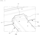
- FIG. 1 is a diagram illustrating a sheet cross member according to the prior art.
- a sheet cross member 10 is a reinforcement component provided in preparation for an impact in a vehicle, that is, an impact reinforcement component, and is disposed below the vehicle.
- Such a sheet cross member 10 has a hat-shaped cross-section and comprises one unit component.
- Such a sheet cross member 10 may be manufactured by roll forming as there is no change in cross-sectional shape in a longitudinal direction. That is, the sheet cross member 10 may be welded to a seal side 20 by creating a flange 11 through post-processing at both ends of a roll forming component.
- a structure simply formed of both side walls 10a and a flat upper plate 10b has a limitation in that it lacks reinforcement against impacts.
- a sheet cross member including a bead (a portion raised upwardly relatively compared to other portions) may be formed on an upper plate thereof.
- an end of the sheet cross member is not a simple hat-shaped cross-section, but has a complex cross-sectional shape with a cross-sectional edge which is bent several times due to the beads, it becomes significantly difficult that the end is deformed by being bent to form a flange.
- the sheet cross member is composed of a plurality of unit components rather than one unit component. That is, the unit component with a beaded structure and a separate unit component having a simple hat-shaped cross-sectional structure without beads may be connected to each other (bonded by welding, or the like), to form a sheet cross member.
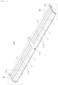
- FIG. 2 is a diagram illustrating an impact reinforcement component according to the present disclosure
- FIG. 3 is an enlarged view illustrating A in FIG. 2
- FIG. 4 is an enlarged view illustrating B in FIG. 2 .
- a boundary portion 120 having a simple cross-sectional structure without a bead (a portion raised upwardly relatively compared to other portions) may be formed at an end thereof, and the boundary portion 120 is composed of an integrated structure rather than a member separate from other portions.
- the present disclosure includes a component body 100 and an end flange 200.
- the component body 100 is formed by continuous repetition of roll stamping in which a stamping roll rotates multiple times and presses a material.
- the component body 100 manufactured through this method has structurally, side walls S formed on both sides in a longitudinal direction, and an upper plate U connecting upper ends of both side walls S.
- the end flange 200 is formed by being bent at each of both ends of the component body 100 in the longitudinal direction.
- the end flange 200 is a portion welded to another component, such as a sill side, as an example.
- the component body 100 includes a body portion 110 and a boundary portion 120.
- the body portion 110 has a bead 111a formed on an upper plate U in a longitudinal direction.
- boundary portion 120 is a connecting portion between the body portion 110 and the end flange 200 and is integrated with the body portion 110 and the end flange 200.
- the upper plate U of the boundary portion 120 has a flat structure without beads.
- the boundary portion 120 is a portion having a substantially short length, and is the same portion as a boundary line between the body portion 110 and the end flange 200.
- the body portion 110 includes a bead region 111 and a middle beadless region 112.
- the plurality of the bead regions 111 are located to be spaced apart from each other in a longitudinal direction, and a bead 111a is formed on the upper plate U. That is, the bead region 111 is formed elongated in the longitudinal direction, and since there is a middle beadless region in the middle, a plurality of bead regions 111 is located to be spaced apart from each other. As an example, as illustrated in the drawings, two bead regions may be disposed to be spaced apart from each other.
- a plurality of bead regions 111 disposed to be spaced apart in the longitudinal direction as described above are formed by being manufactured using roll stamping as described in a method for manufacturing a component to be described later. That is, the material is rotated and pressed multiple times by the stamping rolls, a plurality of beads 111a are formed to be spaced apart in the longitudinal direction.
- a plurality of beads 111a may be arranged on an upper plate U to be spaced apart from each other in a width direction. As described above, when the plurality of bead areas 111 are disposed to be spaced apart in the width direction, the rigidity of the impact reinforcement component 1000 is increased.
- middle beadless region 112 is located between the plurality of bead regions 111, and has a flat upper plate U.
- a plurality of bead regions 111 are disposed in the body portion 110 to be spaced apart from each other in the longitudinal direction, and a middle beadless region 112 having a flat upper plate U is formed between the plurality of bead regions 111, which are spaced apart from each other.
- the stamping roll has a concavo-convex structure to form the bead 111a, and has a flat portion to form the boundary portion 120, and when a size (diameter) of the stamping roll is appropriate considering various factors such as an installation space, in order to manufacture a long impact reinforcement component 1000, as it is rotated and pressed multiple times, a middle beadless region 112 having a flat upper plate U is formed like the boundary portion 120.
- the impact reinforcement component 1000 of the present disclosure may be implemented through a manufacturing method in which a stamping roll rotates multiple times and presses a material.
- the boundary portion 120 is located at each of both ends of the component body 100 in the longitudinal direction, and is a portion having a flat upper plate U and is a portion, the same as a boundary line of the end flange 200, which may allow an end flange 200 to be formed smoothly and easily when formed by being bent.
- the end flange 200 has a structure extending integrally from the boundary portion 120 before deformed by being bent. Since the boundary portion 120 has a simple hat-shaped cross-sectional structure without a bead, bending deformation of the end flange 200 may be smoothly and easily achieved.
- a longitudinal length of the middle beadless region 112 is equal to or greater than twice a longitudinal length obtained by adding the boundary portion 120 and the end flange 200.
- a length of the middle beadless region 112 should be twice a length obtained by adding the boundary portion 120, an end beadless region 121 having a flat upper plate U and the end flange 200, and since a portion thereof may be lost during cutting, in consideration of forming a sufficient end flange 200, the length of the middle beadless region 112 may be more than twice the length thereof.
- FIG. 5 is a flow chart illustrating a method for manufacturing an impact reinforcement component according to the present disclosure
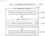
- FIG. 6 is a flow chart illustrating a roll stamping operation in the method for manufacturing the impact reinforcement component of FIG. 5 .
- the method for manufacturing an impact reinforcement component according to the present disclosure includes a roll stamping operation (S100) and a flange forming operation (S200).
- the roll stamping operation (S100) is an operation of continuously repeating a stamping roll rotates multiple times and presses a material in a longitudinal direction.
- the flange forming operation (S200), as an operation which is performed after the roll stamping operation (S100), is an operation of bending each of both ends of the material to form an end flange 200.
- a plurality of bead regions 111 are formed in the material, a middle beadless region 112 is formed between the plurality of bead regions 111, and an end beadless region 121 is formed at each of both ends.
- the roll stamping operation (S100) includes a full bending process (S110), a first end beadless process (S120), a bead process (S130), a middle beadless process (S130), and a second end beadless process (S150).
- a flat upper plate U is formed at one end of the material in the longitudinal direction to form an end beadless region 121.
- a plurality of beads 111a are formed on the upper plate U of the material to be spaced apart from each other in the longitudinal direction to form a plurality of bead regions 111.
- a flat upper plate U is formed between the plurality of beads 111a to form a middle beadless region 112.
- a flat upper plate U is formed at the other end of the material in the longitudinal direction to form an end beadless region 121.
- the first end beadless process (S120), the bead process (S130), the middle beadless process (S130), and the second end beadless process (S150) are performed during the full bending process (S110), and the middle beadless process (S130) is performed during the bead process (S130).
- the first end beadless process (S120), the bead process (S130), and the second end process are sequentially performed, and in this case, the middle beadless process (S130) is performed during the bead process (S130).
- the first end beadless process (S120), the bead process (S130), the middle beadless process (S130), and the second end beadless process (S150) are performed in the process in which the stamping roll rotates multiple times and presses the material.
- an end beadless region 121 having a flat upper surface is bent to form an end flange 200, after the roll stamping operation (S100).
- a longitudinal length of the middle beadless region 112 may be equal to or greater than twice a longitudinal length of the end beadless region 121.
- a length of the middle beadless region 112 should be twice a length of the end beadless region 121 having a flat upper plate U, and since a portion thereof may be lost during cutting, in consideration of forming a sufficient end flange 200, the length of the middle beadless region 112 may be more than twice the length thereof.
- a component body 100 may be formed by continuous competition of roll stamping in which a stamping roll rotates multiple times and presses a material, and a bead region 111 is formed in the body portion 110 of the component body 100, and a boundary portion 120 having a beadless region extends from the body portion 110 and is connected to an end flange 200, which is integrated to the body portion 110 and the end flange 200, so that rigidity may be reinforced by the bead region 111 of the body portion 110, and at the same time, bending deformation of the end flange 200 may be formed smoothly and easily by the beadless region of the boundary portion 120.
- a roll stamping operation of continuously repeating roll stamping in which a stamping roll rotates multiple times and presses a material in a longitudinal direction may be configured, so that a component having a very long length may be manufactured without increasing a diameter of the stamping roll by configuring the component so that a change in shape thereof in the longitudinal direction is periodically repeated, and the boundary portion described above may be easily formed.
Landscapes
- Engineering & Computer Science (AREA)
- Mechanical Engineering (AREA)
- Body Structure For Vehicles (AREA)
- Shaping Metal By Deep-Drawing, Or The Like (AREA)
- Bending Of Plates, Rods, And Pipes (AREA)
Abstract
Description
- The present disclosure relates to an impact reinforcement component and a method for manufacturing the same, and specifically, to an impact reinforcement component with reinforced rigidity to prepare for an impact, such as a sheet cross member, and a method for manufacturing the same.
- A Roll stamping technology is a technology which is disclosed in previously registered patents: Roll Stamping Device (Registration No. 10-1417278), Roll Stamping Device (Registration No. 10-1786260), and Roll Stamping Device and Method (Registration No. 10-1917450).
- The core of roll stamping technology is to manufacture components of which a cross-section changes in a longitudinal direction using a roll forming device.
- However, it is impossible to manufacture components with shape changes in the longitudinal direction while using the conventional roll forming method. Therefore, it is common to manufacture using press molding with a mold. However, when the strength of the material is high, forming of large-sized components requires a very high press capacity, making manufacturing thereof difficult.
- Therefore, roll stamping is a useful technology that can solve such limitations. However, since roll stamping is basically a technology using a roll forming device, it is not easy to be applied realistically when there is a change in shape in the longitudinal direction of an elongated component. That is, since the shape of the component in the longitudinal direction should be engraved around a stamping roll, when the length of the component is relatively long, a diameter of the stamping roll should be increased. Such an increase in the diameter of the stamping roll leads to a problem in which the roll forming device should be significantly enlarged as a whole, so it is difficult to be applied realistically in terms of installation space.
- The present disclosure is provided to solve the above problems, and an aspect of the present disclosure is to provide an impact reinforcement component that can be manufactured by roll stamping without increasing a diameter of a stamping roll when manufacturing components with an elongated material and a method for manufacturing the same.
- According to an aspect of the present disclosure, an impact reinforcement component includes: a component body having side walls on both sides thereof in a longitudinal direction and an upper plate connecting upper ends of the side walls on both sides; and an end flange formed by being bent at each of both ends of the component body in the longitudinal direction, wherein the component body is formed by continuous repetition of roll stamping in which a stamping roll rotates multiple times and presses a material, and the component body includes a body portion having beads formed on an upper plate thereof in a longitudinal direction; and a boundary portion which is integrated with the body portion and the end flange, as a connecting portion between the body portion and the end flange, and has a flat upper plate.
- Here, the body portion may include a plurality of bead regions located to be spaced apart from each other in a longitudinal direction and having the beads formed on an upper plate thereof; and a middle beadless region located between the plurality of bead regions and having a flat upper plate.
- In the case, in the bead region, the plurality of beads may be disposed on the upper plate to be spaced apart from each other in a width direction.
- In addition, a longitudinal length of the middle beadless region may be equal to or greater than twice a longitudinal length obtained by adding the boundary portion and the end flange.
- Meanwhile, according to another aspect of the present disclosure, a method for manufacturing an impact reinforcement component is provided, the method including: a roll stamping operation of continuously repeating roll stamping in which a stamping roll rotates multiple times and presses a material in a longitudinal direction; and a flange forming operation of bending each of both ends of the material to form an end flange, wherein in the roll stamping operation, a plurality of bead regions are formed in the material, a middle beadless region is formed between the plurality of bead regions, and an end beadless region is formed at each of both ends.
- Specifically, the roll stamping operation includes a full bending process in which the stamping roll rotates multiple times and presses the material, to bend the material to form side walls on both sides and an upper plate; a first end beadless process of forming a flat upper plate at one end of the material in a longitudinal direction to form the end beadless region; a bead process of forming a plurality of beads on an upper plate of the material to be spaced apart from each other in the longitudinal direction to form the plurality of bead regions; a middle beadless process of forming a flat upper plate between the plurality of beads to form the middle beadless region; and a second end beadless process of forming a flat upper plate at the other end of the material in the longitudinal direction to form the end beadless region, wherein the first end beadless process, bead process, middle beadless process, and second end beadless process may be performed during the full bending process, and the middle beadless process may be performed during the bead process.
- In this case, a longitudinal length of the middle beadless region formed by the middle beadless process may be equal to or greater than twice a longitudinal length of the end beadless region formed by the first end beadless process or the second end beadless process.
- As set forth above, in the impact reinforcement component, as a component body is formed by continuous repetition of roll stamping in which a stamping roll rotates multiple times and presses a material, a bead region is formed in a body portion of the component body, and a boundary portion having a beadless region extends from the body portion thereof and is connected to an end flange, which is integrated with the body portion and the end flange, rigidity may be reinforced by the bead region of the body portion, and at the same time, bending deformation of the end flange by the beadless region of the boundary portion is formed smoothly and easily.
- In the method for manufacturing an impact reinforcement component according to the present disclosure, a roll stamping operation in which a stamping roll rotates multiple times and presses a material in a longitudinal direction may be performed, so that a component having a very long length may be manufactured without increasing a diameter of the stamping roll by configuring the component so that a change in shape thereof in the longitudinal direction is periodically repeated, and the boundary portion described above may be easily formed.
-
-
FIG. 1 is a diagram illustrating a sheet cross member according to the prior art. -
FIG. 2 is a diagram illustrating an impact reinforcement component according to the present disclosure. -
FIG. 3 is an enlarged view illustrating A inFIG. 2 . -
FIG. 4 is an enlarged view illustrating B inFIG. 2 . -
FIG. 5 is a flow chart illustrating a method for manufacturing an impact reinforcement component according to the present disclosure. -
FIG. 6 is a flow chart showing the roll stamping operation in the method for manufacturing an impact reinforcement component ofFIG. 5 . - Hereinafter, preferred embodiments of the present disclosure will be described in detail so that those skilled in the art could easily practice the present disclosure with reference to the accompanying drawings. However, in describing a preferred embodiment of the present disclosure in detail, if it is determined that a detailed description of a related known function or configuration may unnecessarily obscure the subject matter of the present disclosure, the detailed description will be omitted. In addition, the same reference numerals are used throughout the drawings for parts having similar functions and actions. In addition, in the present specification, terms such as 'upper,' 'upper portion,' 'upper surface,' 'lower,' 'lower portion,' 'lower surface,' 'side surface,' and the like are based on the drawings, and in practice, it may be different depending on a direction in which the components are disposed.
- In addition, throughout the specification, when a part is said to be 'connected' to another part, this is not only when it is 'directly connected,' but also when it is 'indirectly connected' with other components therebetween. In addition, 'including' a certain component means that other components may be further included without excluding other components unless otherwise stated.
-
FIG. 1 is a diagram illustrating a sheet cross member according to the prior art. - Referring
FIG. 1 , asheet cross member 10 is a reinforcement component provided in preparation for an impact in a vehicle, that is, an impact reinforcement component, and is disposed below the vehicle. - Such a
sheet cross member 10 has a hat-shaped cross-section and comprises one unit component. - Such a
sheet cross member 10 may be manufactured by roll forming as there is no change in cross-sectional shape in a longitudinal direction. That is, thesheet cross member 10 may be welded to aseal side 20 by creating aflange 11 through post-processing at both ends of a roll forming component. - However, a structure simply formed of both
side walls 10a and a flatupper plate 10b has a limitation in that it lacks reinforcement against impacts. - To overcome such a limitation, although not shown in the drawings, a sheet cross member including a bead (a portion raised upwardly relatively compared to other portions) may be formed on an upper plate thereof.
- However, when beads are formed on an entire upper plate in a longitudinal direction, that is, when beads are formed elongated to both ends in the longitudinal direction, it becomes very difficult to form a flange which is deformed by being bent during the manufacturing process.
- In other words, an end of the sheet cross member is not a simple hat-shaped cross-section, but has a complex cross-sectional shape with a cross-sectional edge which is bent several times due to the beads, it becomes significantly difficult that the end is deformed by being bent to form a flange.
- Accordingly, in order to form a simple hat-shaped cross-sectional structure without beads only at the end of the sheet cross member, the sheet cross member is composed of a plurality of unit components rather than one unit component. That is, the unit component with a beaded structure and a separate unit component having a simple hat-shaped cross-sectional structure without beads may be connected to each other (bonded by welding, or the like), to form a sheet cross member.
- However, in the case of a simple model cross-sectional structure without beads at an end thereof, it is easy to form a flange by bending and changing the end thereof, but when a sheet cross member is created by combining a plurality of unit components, which are not integrated, the rigidity of a portion to which unit components are connected (for example, a welded portion) is relatively low compared to other portions, so there is a problem of being used as an impact reinforcement component.
-
FIG. 2 is a diagram illustrating an impact reinforcement component according to the present disclosure,FIG. 3 is an enlarged view illustrating A inFIG. 2 , andFIG. 4 is an enlarged view illustrating B inFIG. 2 . - Referring to the
FIGS. 2 ,3 , and4 , theimpact reinforcement component 1000 according to the present disclosure, in order to solve the above-described problem, aboundary portion 120 having a simple cross-sectional structure without a bead (a portion raised upwardly relatively compared to other portions) may be formed at an end thereof, and theboundary portion 120 is composed of an integrated structure rather than a member separate from other portions. - Specifically, the present disclosure includes a
component body 100 and anend flange 200. - The
component body 100 is formed by continuous repetition of roll stamping in which a stamping roll rotates multiple times and presses a material. - The
component body 100 manufactured through this method has structurally, side walls S formed on both sides in a longitudinal direction, and an upper plate U connecting upper ends of both side walls S. - The
end flange 200 is formed by being bent at each of both ends of thecomponent body 100 in the longitudinal direction. Theend flange 200 is a portion welded to another component, such as a sill side, as an example. - Here, the
component body 100 includes abody portion 110 and aboundary portion 120. - The
body portion 110 has abead 111a formed on an upper plate U in a longitudinal direction. - In addition, the
boundary portion 120 is a connecting portion between thebody portion 110 and theend flange 200 and is integrated with thebody portion 110 and theend flange 200. - In this case, the upper plate U of the
boundary portion 120 has a flat structure without beads. Theboundary portion 120 is a portion having a substantially short length, and is the same portion as a boundary line between thebody portion 110 and theend flange 200. - More specifically, the
body portion 110 includes abead region 111 and amiddle beadless region 112. - The plurality of the
bead regions 111 are located to be spaced apart from each other in a longitudinal direction, and abead 111a is formed on the upper plate U. That is, thebead region 111 is formed elongated in the longitudinal direction, and since there is a middle beadless region in the middle, a plurality ofbead regions 111 is located to be spaced apart from each other. As an example, as illustrated in the drawings, two bead regions may be disposed to be spaced apart from each other. - A plurality of
bead regions 111 disposed to be spaced apart in the longitudinal direction as described above are formed by being manufactured using roll stamping as described in a method for manufacturing a component to be described later. That is, the material is rotated and pressed multiple times by the stamping rolls, a plurality ofbeads 111a are formed to be spaced apart in the longitudinal direction. - Furthermore, in the
bead region 111, a plurality ofbeads 111a may be arranged on an upper plate U to be spaced apart from each other in a width direction. As described above, when the plurality ofbead areas 111 are disposed to be spaced apart in the width direction, the rigidity of theimpact reinforcement component 1000 is increased. - In addition, the middle
beadless region 112 is located between the plurality ofbead regions 111, and has a flat upper plate U. - As described above, a plurality of
bead regions 111 are disposed in thebody portion 110 to be spaced apart from each other in the longitudinal direction, and a middlebeadless region 112 having a flat upper plate U is formed between the plurality ofbead regions 111, which are spaced apart from each other. - The stamping roll has a concavo-convex structure to form the
bead 111a, and has a flat portion to form theboundary portion 120, and when a size (diameter) of the stamping roll is appropriate considering various factors such as an installation space, in order to manufacture a longimpact reinforcement component 1000, as it is rotated and pressed multiple times, a middlebeadless region 112 having a flat upper plate U is formed like theboundary portion 120. - That is, due to the same structure as the middle
beadless region 112, theimpact reinforcement component 1000 of the present disclosure may be implemented through a manufacturing method in which a stamping roll rotates multiple times and presses a material. - The
boundary portion 120 is located at each of both ends of thecomponent body 100 in the longitudinal direction, and is a portion having a flat upper plate U and is a portion, the same as a boundary line of theend flange 200, which may allow anend flange 200 to be formed smoothly and easily when formed by being bent. - The
end flange 200 has a structure extending integrally from theboundary portion 120 before deformed by being bent. Since theboundary portion 120 has a simple hat-shaped cross-sectional structure without a bead, bending deformation of theend flange 200 may be smoothly and easily achieved. - In the present disclosure, in a manufacturing method in which a stamping roll rotates multiple times, a longitudinal length of the middle
beadless region 112 is equal to or greater than twice a longitudinal length obtained by adding theboundary portion 120 and theend flange 200. - When manufacturing a plurality of
impact reinforcement components 1000 with a set length using a long material, since the material is roll stamped and then cut and divided to form a plurality ofimpact reinforcement components 1000, a length of the middlebeadless region 112 should be twice a length obtained by adding theboundary portion 120, anend beadless region 121 having a flat upper plate U and theend flange 200, and since a portion thereof may be lost during cutting, in consideration of forming asufficient end flange 200, the length of the middlebeadless region 112 may be more than twice the length thereof. -
FIG. 5 is a flow chart illustrating a method for manufacturing an impact reinforcement component according to the present disclosure, andFIG. 6 is a flow chart illustrating a roll stamping operation in the method for manufacturing the impact reinforcement component ofFIG. 5 . - Referring to
FIGS. 5 and6 based onFIGS. 2 to 4 , the method for manufacturing an impact reinforcement component according to the present disclosure includes a roll stamping operation (S100) and a flange forming operation (S200). - The roll stamping operation (S100) is an operation of continuously repeating a stamping roll rotates multiple times and presses a material in a longitudinal direction.
- In addition, the flange forming operation (S200), as an operation which is performed after the roll stamping operation (S100), is an operation of bending each of both ends of the material to form an
end flange 200. - When manufacturing an impact reinforcement component such as a sheet cross member using a material with a long shape in the longitudinal direction, a product is completed through the roll stamping operation (S100) and the flange forming operation (S200).
- Here, in the roll stamping operation (S100), a plurality of
bead regions 111 are formed in the material, a middlebeadless region 112 is formed between the plurality ofbead regions 111, and anend beadless region 121 is formed at each of both ends. - Specifically, the roll stamping operation (S100) includes a full bending process (S110), a first end beadless process (S120), a bead process (S130), a middle beadless process (S130), and a second end beadless process (S150).
- In the full bending process (S110), the material is bent while pressing and rotating the stamping roll multiple times to form side walls on both sides S and an upper plate U of the material.
- In addition, in the first end beadless process (S120), a flat upper plate U is formed at one end of the material in the longitudinal direction to form an
end beadless region 121. - In the bead process (S130), a plurality of
beads 111a are formed on the upper plate U of the material to be spaced apart from each other in the longitudinal direction to form a plurality ofbead regions 111. - In addition, in the middle beadless process (S130), a flat upper plate U is formed between the plurality of
beads 111a to form a middlebeadless region 112. - In addition, in the second end beadless process (S150), a flat upper plate U is formed at the other end of the material in the longitudinal direction to form an
end beadless region 121. - In this case, the first end beadless process (S120), the bead process (S130), the middle beadless process (S130), and the second end beadless process (S150) are performed during the full bending process (S110), and the middle beadless process (S130) is performed during the bead process (S130).
- That is, in the process of forming both side walls S and an upper plate U in the material while the stamping roll rotates multiple times and presses the material, the first end beadless process (S120), the bead process (S130), and the second end process are sequentially performed, and in this case, the middle beadless process (S130) is performed during the bead process (S130). In other words, the first end beadless process (S120), the bead process (S130), the middle beadless process (S130), and the second end beadless process (S150) are performed in the process in which the stamping roll rotates multiple times and presses the material.
- In the flange forming operation (S200), an
end beadless region 121 having a flat upper surface is bent to form anend flange 200, after the roll stamping operation (S100). - Meanwhile, a longitudinal length of the middle
beadless region 112 may be equal to or greater than twice a longitudinal length of theend beadless region 121. - When manufacturing a plurality of
impact reinforcement components 1000 with a set length using a long material, since the material is roll stamped in the roll stamping operation (S100) and then cut and divided to form a plurality ofimpact reinforcement components 1000, a length of the middlebeadless region 112 should be twice a length of theend beadless region 121 having a flat upper plate U, and since a portion thereof may be lost during cutting, in consideration of forming asufficient end flange 200, the length of the middlebeadless region 112 may be more than twice the length thereof. - As a result, in the
impact reinforcement component 1000 according to the present disclosure, acomponent body 100 may be formed by continuous competition of roll stamping in which a stamping roll rotates multiple times and presses a material, and abead region 111 is formed in thebody portion 110 of thecomponent body 100, and aboundary portion 120 having a beadless region extends from thebody portion 110 and is connected to anend flange 200, which is integrated to thebody portion 110 and theend flange 200, so that rigidity may be reinforced by thebead region 111 of thebody portion 110, and at the same time, bending deformation of theend flange 200 may be formed smoothly and easily by the beadless region of theboundary portion 120. - In the method for manufacturing an impact reinforcement component according to the present disclosure, a roll stamping operation of continuously repeating roll stamping in which a stamping roll rotates multiple times and presses a material in a longitudinal direction may be configured, so that a component having a very long length may be manufactured without increasing a diameter of the stamping roll by configuring the component so that a change in shape thereof in the longitudinal direction is periodically repeated, and the boundary portion described above may be easily formed.
- While example embodiments have been shown and described above, it will be apparent to those skilled in the art that modifications and variations could be made without departing from the scope of the present disclosure as defined by the appended claims.
-
- 100: COMPONENT BODY 110: BODY PORTION
- 111: BEAD REGION 111A: BEAD
- 112: MIDDLE BEADLESS REGION 120: BOUNDARY PORTION
- 121: END BEADLESS REGION 200: END FLANGE
- 1000: IMPACT REINFORCEMENT COMPONENT S: SIDE WALL
- U: UPPER PLATE S100: ROLL STAMPING OPERATION
- S110: FULL BENDING PROCESS S120: FIRST END BEADLESS PROCESS
- S130: BEAD PROCESS S140: MIDDLE BEAD PROCESS
- S150: SECOND END BEADLESS PROCESS S200: FLANGE FORMING OPERATION
Claims (7)
- An impact reinforcement component, comprising:a component body having side walls on both sides thereof in a longitudinal direction and an upper plate connecting upper ends of the side walls on both sides; andan end flange formed by being bent at each of both ends of the component body in the longitudinal direction,wherein the component body is formed by continuous repetition of roll stamping in which a stamping roll rotates multiple times and presses a material,wherein the component body includesa body portion having a plurality of beads formed on an upper plate in a longitudinal direction; anda boundary portion which is integrated with the body portion and the end flange, as a connecting portion between the body portion and the end flange, and has a flat upper plate.
- The impact reinforcement component of claim 1, wherein the body portion comprisesa plurality of bead regions located to be spaced apart from each other in a longitudinal direction and have the beads formed on an upper plate thereof; anda middle beadless region located between the plurality of bead regions and having a flat upper plate.
- The impact reinforcement component of claim 2, wherein the bead region has the plurality of beads disposed on the upper plate to be spaced apart from each other in a width direction.
- The impact reinforcement component of claim 2, wherein a longitudinal length of the middle beadless region is equal to or greater than twice a longitudinal length obtained by adding the boundary portion and the end flange.
- A method for manufacturing an impact reinforcement component, comprising:a roll stamping operation of continuously repeating roll stamping in which a stamping roll rotates multiple times and presses a material in a longitudinal direction; anda flange forming operation of bending each of both ends of the material to form an end flange,wherein in the roll stamping operation, a plurality of bead regions are formed in the material, a middle beadless region is formed between the plurality of bead regions, and an end beadless region is formed at each of both ends.
- The method for manufacturing an impact reinforcement component of claim 5, wherein the roll stamping operation comprisesa full bending process in which the stamping roll rotates multiple times and presses the material, to bend the material to form side walls on both sides and an upper plate;a first end beadless process of forming a flat upper plate at one end of the material in a longitudinal direction to form the end beadless region;a bead process of forming a plurality of beads on an upper plate of the material to be spaced apart from each other in the longitudinal direction to form the plurality of bead regions;a middle beadless process of forming a flat upper plate between the plurality of beads to form the middle beadless region; anda second end beadless process of forming a flat upper plate at the other end of the material in the longitudinal direction to form the end beadless region,wherein the first end beadless process, bead process, middle beadless process, and second end beadless process are performed during the full bending process, and the middle beadless process is performed during the bead process.
- The method for manufacturing an impact reinforcement component of claim 6, wherein a longitudinal length of the middle beadless region formed by the middle beadless process is equal to or greater than twice a longitudinal length of the end beadless region formed by the first end beadless process or the second end beadless process.
Applications Claiming Priority (2)
| Application Number | Priority Date | Filing Date | Title |
|---|---|---|---|
| KR1020210179479A KR20230090587A (en) | 2021-12-15 | 2021-12-15 | Impact reinforcement component and method for manufacturing thereof |
| PCT/KR2022/020308 WO2023113455A1 (en) | 2021-12-15 | 2022-12-15 | Impact reinforcement component and method for manufacturing same |
Publications (2)
| Publication Number | Publication Date |
|---|---|
| EP4450182A1 true EP4450182A1 (en) | 2024-10-23 |
| EP4450182A4 EP4450182A4 (en) | 2025-04-02 |
Family
ID=86773009
Family Applications (1)
| Application Number | Title | Priority Date | Filing Date |
|---|---|---|---|
| EP22907922.3A Pending EP4450182A4 (en) | 2021-12-15 | 2022-12-15 | IMPACT REINFORCING COMPONENT AND METHOD FOR MANUFACTURING SAME |
Country Status (6)
| Country | Link |
|---|---|
| US (1) | US20250326020A1 (en) |
| EP (1) | EP4450182A4 (en) |
| JP (1) | JP7823937B2 (en) |
| KR (1) | KR20230090587A (en) |
| CN (1) | CN118382505A (en) |
| WO (1) | WO2023113455A1 (en) |
Family Cites Families (13)
| Publication number | Priority date | Publication date | Assignee | Title |
|---|---|---|---|---|
| JP4419716B2 (en) * | 2004-02-16 | 2010-02-24 | 株式会社デンソー | Press working method and press working apparatus |
| JP4769169B2 (en) * | 2006-11-15 | 2011-09-07 | 豊臣機工株式会社 | Energy absorbing member for vehicles |
| KR101146121B1 (en) * | 2009-12-28 | 2012-05-16 | 재단법인 포항산업과학연구원 | Thermal Insulation Stud and Method for Manufacturing The Same |
| KR20130070388A (en) * | 2011-12-19 | 2013-06-27 | 주식회사 성우하이텍 | Bumper beam for vehicles |
| KR101359164B1 (en) * | 2012-05-16 | 2014-02-06 | 주식회사 포스코 | Bumper beam for vehicle |
| KR101417278B1 (en) | 2012-05-25 | 2014-07-08 | 주식회사 포스코 | Apparatus for roll stamping |
| KR101449190B1 (en) * | 2012-12-21 | 2014-10-08 | 주식회사 포스코 | Method for manufacturing one body type high strength vehicle parts using md-rf process |
| US20140377484A1 (en) * | 2013-06-24 | 2014-12-25 | Shape Corp. | Roll form apparatus, method to manufacture crush tubes |
| CA2986084C (en) | 2015-06-01 | 2020-04-14 | Nippon Steel Corporation | Press-formed article, press-forming method, and press-forming apparatus |
| KR101786260B1 (en) | 2015-12-23 | 2017-10-18 | 주식회사 포스코 | Roll Stamping Device |
| KR101917450B1 (en) | 2016-12-21 | 2018-11-09 | 주식회사 포스코 | Roll Stamping Device and Method |
| DE102017002918A1 (en) | 2017-03-25 | 2018-09-27 | GM Global Technology Operations LLC (n. d. Ges. d. Staates Delaware) | Rollformteil, vehicle body and manufacturing process for it |
| CN113695462A (en) * | 2021-08-17 | 2021-11-26 | 江西源金科技集团有限公司 | Integrated cabinet stand punching press forming system of bending |
-
2021
- 2021-12-15 KR KR1020210179479A patent/KR20230090587A/en active Pending
-
2022
- 2022-12-15 EP EP22907922.3A patent/EP4450182A4/en active Pending
- 2022-12-15 US US18/709,375 patent/US20250326020A1/en active Pending
- 2022-12-15 CN CN202280082447.0A patent/CN118382505A/en active Pending
- 2022-12-15 JP JP2024529159A patent/JP7823937B2/en active Active
- 2022-12-15 WO PCT/KR2022/020308 patent/WO2023113455A1/en not_active Ceased
Also Published As
| Publication number | Publication date |
|---|---|
| US20250326020A1 (en) | 2025-10-23 |
| JP2024545599A (en) | 2024-12-10 |
| EP4450182A4 (en) | 2025-04-02 |
| WO2023113455A1 (en) | 2023-06-22 |
| CN118382505A (en) | 2024-07-23 |
| KR20230090587A (en) | 2023-06-22 |
| JP7823937B2 (en) | 2026-03-04 |
Similar Documents
| Publication | Publication Date | Title |
|---|---|---|
| KR100935018B1 (en) | Beam formed by plank and making method thereof | |
| US7971466B2 (en) | Press-formed member having corner portion, press-formed member manufacturing apparatus and press-formed member manufacturing method | |
| US10391537B2 (en) | Method and system for flanging a metal piece | |
| US7637555B2 (en) | Door panel structure and method of producing the same | |
| WO2012124733A1 (en) | Vehicular arm component and production method therefor | |
| CN103286185A (en) | Press product forming method | |
| TWI590885B (en) | A method of manufacturing a press-formed product and a press-formed product, and a manufacturing apparatus of the press-formed product | |
| JPH03291115A (en) | Manufacture of tapered pipe with axial center bent from plate material | |
| JP2012121377A (en) | Frame member and method for manufacturing the same | |
| US20250326020A1 (en) | Impact reinforcement component and method for manufacturing same | |
| JP2007029966A (en) | Partial overlap molding method | |
| JPH0337443B2 (en) | ||
| JP6788828B2 (en) | Vehicle roof structure and manufacturing method of vehicle roof panel | |
| JP2007509795A (en) | Method of manufacturing pivot beam torsion beam axle and cross member | |
| JP2000153314A (en) | Method of manufacturing body structural member | |
| JP3685710B2 (en) | Rack bar and its manufacturing method | |
| JP4083613B2 (en) | Axle housing | |
| CN101209469A (en) | A method for forming a part with a concave structure in drawing shape | |
| JP2000135520A (en) | Press molding die equipment | |
| JP5750357B2 (en) | Roof panel and method for manufacturing the roof panel | |
| JP7704721B2 (en) | Manufacturing method of press-molded products | |
| JP2606227Y2 (en) | Assembly of rubber segment and holding plate | |
| JP7110423B1 (en) | BODY FRAME AND METHOD FOR MANUFACTURING BODY FRAME | |
| JPH11347642A (en) | Press molding die equipment | |
| JPH01162522A (en) | Forming method for corner round square cylindrical body |
Legal Events
| Date | Code | Title | Description |
|---|---|---|---|
| STAA | Information on the status of an ep patent application or granted ep patent |
Free format text: STATUS: THE INTERNATIONAL PUBLICATION HAS BEEN MADE |
|
| PUAI | Public reference made under article 153(3) epc to a published international application that has entered the european phase |
Free format text: ORIGINAL CODE: 0009012 |
|
| STAA | Information on the status of an ep patent application or granted ep patent |
Free format text: STATUS: REQUEST FOR EXAMINATION WAS MADE |
|
| 17P | Request for examination filed |
Effective date: 20240628 |
|
| AK | Designated contracting states |
Kind code of ref document: A1 Designated state(s): AL AT BE BG CH CY CZ DE DK EE ES FI FR GB GR HR HU IE IS IT LI LT LU LV MC ME MK MT NL NO PL PT RO RS SE SI SK SM TR |
|
| DAV | Request for validation of the european patent (deleted) | ||
| DAX | Request for extension of the european patent (deleted) | ||
| A4 | Supplementary search report drawn up and despatched |
Effective date: 20250228 |
|
| RIC1 | Information provided on ipc code assigned before grant |
Ipc: B21D 53/88 20060101ALI20250224BHEP Ipc: B21D 22/08 20060101ALI20250224BHEP Ipc: B21D 22/04 20060101AFI20250224BHEP |