EP4450172A1 - Apparatus and method for inspecting and repairing dispensed viscous fluid - Google Patents
Apparatus and method for inspecting and repairing dispensed viscous fluid Download PDFInfo
- Publication number
- EP4450172A1 EP4450172A1 EP24155395.7A EP24155395A EP4450172A1 EP 4450172 A1 EP4450172 A1 EP 4450172A1 EP 24155395 A EP24155395 A EP 24155395A EP 4450172 A1 EP4450172 A1 EP 4450172A1
- Authority
- EP
- European Patent Office
- Prior art keywords
- viscous fluid
- air
- module
- dispensed
- nozzle
- Prior art date
- Legal status (The legal status is an assumption and is not a legal conclusion. Google has not performed a legal analysis and makes no representation as to the accuracy of the status listed.)
- Granted
Links
Images




Classifications
-
- G—PHYSICS
- G01—MEASURING; TESTING
- G01N—INVESTIGATING OR ANALYSING MATERIALS BY DETERMINING THEIR CHEMICAL OR PHYSICAL PROPERTIES
- G01N21/00—Investigating or analysing materials by the use of optical means, i.e. using sub-millimetre waves, infrared, visible or ultraviolet light
- G01N21/84—Systems specially adapted for particular applications
- G01N21/88—Investigating the presence of flaws or contamination
- G01N21/8851—Scan or image signal processing specially adapted therefor, e.g. for scan signal adjustment, for detecting different kinds of defects, for compensating for structures, markings, edges
-
- B—PERFORMING OPERATIONS; TRANSPORTING
- B05—SPRAYING OR ATOMISING IN GENERAL; APPLYING FLUENT MATERIALS TO SURFACES, IN GENERAL
- B05C—APPARATUS FOR APPLYING FLUENT MATERIALS TO SURFACES, IN GENERAL
- B05C5/00—Apparatus in which liquid or other fluent material is projected, poured or allowed to flow on to the surface of the work
- B05C5/02—Apparatus in which liquid or other fluent material is projected, poured or allowed to flow on to the surface of the work the liquid or other fluent material being discharged through an outlet orifice by pressure, e.g. from an outlet device in contact or almost in contact, with the work
- B05C5/0208—Apparatus in which liquid or other fluent material is projected, poured or allowed to flow on to the surface of the work the liquid or other fluent material being discharged through an outlet orifice by pressure, e.g. from an outlet device in contact or almost in contact, with the work for applying liquid or other fluent material to separate articles
- B05C5/0212—Apparatus in which liquid or other fluent material is projected, poured or allowed to flow on to the surface of the work the liquid or other fluent material being discharged through an outlet orifice by pressure, e.g. from an outlet device in contact or almost in contact, with the work for applying liquid or other fluent material to separate articles only at particular parts of the articles
- B05C5/0216—Apparatus in which liquid or other fluent material is projected, poured or allowed to flow on to the surface of the work the liquid or other fluent material being discharged through an outlet orifice by pressure, e.g. from an outlet device in contact or almost in contact, with the work for applying liquid or other fluent material to separate articles only at particular parts of the articles by relative movement of article and outlet according to a predetermined path
-
- B—PERFORMING OPERATIONS; TRANSPORTING
- B05—SPRAYING OR ATOMISING IN GENERAL; APPLYING FLUENT MATERIALS TO SURFACES, IN GENERAL
- B05C—APPARATUS FOR APPLYING FLUENT MATERIALS TO SURFACES, IN GENERAL
- B05C11/00—Component parts, details or accessories not specifically provided for in groups B05C1/00 - B05C9/00
- B05C11/02—Apparatus for spreading or distributing liquids or other fluent materials already applied to a surface ; Controlling means therefor; Control of the thickness of a coating by spreading or distributing liquids or other fluent materials already applied to the coated surface
- B05C11/06—Apparatus for spreading or distributing liquids or other fluent materials already applied to a surface ; Controlling means therefor; Control of the thickness of a coating by spreading or distributing liquids or other fluent materials already applied to the coated surface with a blast of gas or vapour
-
- B—PERFORMING OPERATIONS; TRANSPORTING
- B05—SPRAYING OR ATOMISING IN GENERAL; APPLYING FLUENT MATERIALS TO SURFACES, IN GENERAL
- B05B—SPRAYING APPARATUS; ATOMISING APPARATUS; NOZZLES
- B05B1/00—Nozzles, spray heads or other outlets, with or without auxiliary devices such as valves, heating means
- B05B1/005—Nozzles or other outlets specially adapted for discharging one or more gases
-
- B—PERFORMING OPERATIONS; TRANSPORTING
- B05—SPRAYING OR ATOMISING IN GENERAL; APPLYING FLUENT MATERIALS TO SURFACES, IN GENERAL
- B05C—APPARATUS FOR APPLYING FLUENT MATERIALS TO SURFACES, IN GENERAL
- B05C11/00—Component parts, details or accessories not specifically provided for in groups B05C1/00 - B05C9/00
- B05C11/10—Storage, supply or control of liquid or other fluent material; Recovery of excess liquid or other fluent material
- B05C11/1002—Means for controlling supply, i.e. flow or pressure, of liquid or other fluent material to the applying apparatus, e.g. valves
- B05C11/1005—Means for controlling supply, i.e. flow or pressure, of liquid or other fluent material to the applying apparatus, e.g. valves responsive to condition of liquid or other fluent material already applied to the surface, e.g. coating thickness, weight or pattern
-
- B—PERFORMING OPERATIONS; TRANSPORTING
- B05—SPRAYING OR ATOMISING IN GENERAL; APPLYING FLUENT MATERIALS TO SURFACES, IN GENERAL
- B05C—APPARATUS FOR APPLYING FLUENT MATERIALS TO SURFACES, IN GENERAL
- B05C5/00—Apparatus in which liquid or other fluent material is projected, poured or allowed to flow on to the surface of the work
- B05C5/02—Apparatus in which liquid or other fluent material is projected, poured or allowed to flow on to the surface of the work the liquid or other fluent material being discharged through an outlet orifice by pressure, e.g. from an outlet device in contact or almost in contact, with the work
-
- G—PHYSICS
- G01—MEASURING; TESTING
- G01N—INVESTIGATING OR ANALYSING MATERIALS BY DETERMINING THEIR CHEMICAL OR PHYSICAL PROPERTIES
- G01N21/00—Investigating or analysing materials by the use of optical means, i.e. using sub-millimetre waves, infrared, visible or ultraviolet light
- G01N21/84—Systems specially adapted for particular applications
- G01N21/88—Investigating the presence of flaws or contamination
- G01N21/95—Investigating the presence of flaws or contamination characterised by the material or shape of the object to be examined
- G01N21/956—Inspecting patterns on the surface of objects
- G01N21/95607—Inspecting patterns on the surface of objects using a comparative method
-
- G—PHYSICS
- G06—COMPUTING OR CALCULATING; COUNTING
- G06T—IMAGE DATA PROCESSING OR GENERATION, IN GENERAL
- G06T7/00—Image analysis
- G06T7/0002—Inspection of images, e.g. flaw detection
- G06T7/0004—Industrial image inspection
-
- H—ELECTRICITY
- H01—ELECTRIC ELEMENTS
- H01M—PROCESSES OR MEANS, e.g. BATTERIES, FOR THE DIRECT CONVERSION OF CHEMICAL ENERGY INTO ELECTRICAL ENERGY
- H01M10/00—Secondary cells; Manufacture thereof
- H01M10/04—Construction or manufacture in general
- H01M10/0404—Machines for assembling batteries
-
- H—ELECTRICITY
- H01—ELECTRIC ELEMENTS
- H01M—PROCESSES OR MEANS, e.g. BATTERIES, FOR THE DIRECT CONVERSION OF CHEMICAL ENERGY INTO ELECTRICAL ENERGY
- H01M50/00—Constructional details or processes of manufacture of the non-active parts of electrochemical cells other than fuel cells, e.g. hybrid cells
- H01M50/20—Mountings; Secondary casings or frames; Racks, modules or packs; Suspension devices; Shock absorbers; Transport or carrying devices; Holders
- H01M50/204—Racks, modules or packs for multiple batteries or multiple cells
-
- B—PERFORMING OPERATIONS; TRANSPORTING
- B05—SPRAYING OR ATOMISING IN GENERAL; APPLYING FLUENT MATERIALS TO SURFACES, IN GENERAL
- B05C—APPARATUS FOR APPLYING FLUENT MATERIALS TO SURFACES, IN GENERAL
- B05C9/00—Apparatus or plant for applying liquid or other fluent material to surfaces by means not covered by any preceding group, or in which the means of applying the liquid or other fluent material is not important
- B05C9/06—Apparatus or plant for applying liquid or other fluent material to surfaces by means not covered by any preceding group, or in which the means of applying the liquid or other fluent material is not important for applying two different liquids or other fluent materials, or the same liquid or other fluent material twice, to the same side of the work
-
- B—PERFORMING OPERATIONS; TRANSPORTING
- B05—SPRAYING OR ATOMISING IN GENERAL; APPLYING FLUENT MATERIALS TO SURFACES, IN GENERAL
- B05C—APPARATUS FOR APPLYING FLUENT MATERIALS TO SURFACES, IN GENERAL
- B05C9/00—Apparatus or plant for applying liquid or other fluent material to surfaces by means not covered by any preceding group, or in which the means of applying the liquid or other fluent material is not important
- B05C9/08—Apparatus or plant for applying liquid or other fluent material to surfaces by means not covered by any preceding group, or in which the means of applying the liquid or other fluent material is not important for applying liquid or other fluent material and performing an auxiliary operation
- B05C9/12—Apparatus or plant for applying liquid or other fluent material to surfaces by means not covered by any preceding group, or in which the means of applying the liquid or other fluent material is not important for applying liquid or other fluent material and performing an auxiliary operation the auxiliary operation being performed after the application
-
- G—PHYSICS
- G01—MEASURING; TESTING
- G01N—INVESTIGATING OR ANALYSING MATERIALS BY DETERMINING THEIR CHEMICAL OR PHYSICAL PROPERTIES
- G01N21/00—Investigating or analysing materials by the use of optical means, i.e. using sub-millimetre waves, infrared, visible or ultraviolet light
- G01N21/84—Systems specially adapted for particular applications
- G01N21/88—Investigating the presence of flaws or contamination
- G01N21/8851—Scan or image signal processing specially adapted therefor, e.g. for scan signal adjustment, for detecting different kinds of defects, for compensating for structures, markings, edges
- G01N2021/8854—Grading and classifying of flaws
-
- G—PHYSICS
- G01—MEASURING; TESTING
- G01N—INVESTIGATING OR ANALYSING MATERIALS BY DETERMINING THEIR CHEMICAL OR PHYSICAL PROPERTIES
- G01N21/00—Investigating or analysing materials by the use of optical means, i.e. using sub-millimetre waves, infrared, visible or ultraviolet light
- G01N21/84—Systems specially adapted for particular applications
- G01N21/88—Investigating the presence of flaws or contamination
- G01N21/8851—Scan or image signal processing specially adapted therefor, e.g. for scan signal adjustment, for detecting different kinds of defects, for compensating for structures, markings, edges
- G01N2021/8887—Scan or image signal processing specially adapted therefor, e.g. for scan signal adjustment, for detecting different kinds of defects, for compensating for structures, markings, edges based on image processing techniques
-
- G—PHYSICS
- G06—COMPUTING OR CALCULATING; COUNTING
- G06T—IMAGE DATA PROCESSING OR GENERATION, IN GENERAL
- G06T2207/00—Indexing scheme for image analysis or image enhancement
- G06T2207/20—Special algorithmic details
- G06T2207/20212—Image combination
-
- G—PHYSICS
- G06—COMPUTING OR CALCULATING; COUNTING
- G06T—IMAGE DATA PROCESSING OR GENERATION, IN GENERAL
- G06T2207/00—Indexing scheme for image analysis or image enhancement
- G06T2207/30—Subject of image; Context of image processing
- G06T2207/30108—Industrial image inspection
- G06T2207/30164—Workpiece; Machine component
-
- H—ELECTRICITY
- H01—ELECTRIC ELEMENTS
- H01M—PROCESSES OR MEANS, e.g. BATTERIES, FOR THE DIRECT CONVERSION OF CHEMICAL ENERGY INTO ELECTRICAL ENERGY
- H01M50/00—Constructional details or processes of manufacture of the non-active parts of electrochemical cells other than fuel cells, e.g. hybrid cells
- H01M50/20—Mountings; Secondary casings or frames; Racks, modules or packs; Suspension devices; Shock absorbers; Transport or carrying devices; Holders
- H01M50/244—Secondary casings; Racks; Suspension devices; Carrying devices; Holders characterised by their mounting method
Definitions
- the disclosed technology relates to an apparatus and a method for inspecting and repairing a dispensed viscous fluid.
- Thermal adhesive may be used in the process of manufacturing a battery module.
- Thermal adhesive which is a viscous fluid, may be applied to the battery module by a dispenser.
- the shape of thermal adhesive applied to the battery module may affect the cooling performance of the battery module.
- impact or vibration is applied to the battery module, parts to which the thermal adhesive is poorly applied may be damaged. Accordingly, it is necessary to check whether the thermal adhesive satisfies a predetermined application quality.
- the disclosed technology provides an apparatus and a method for inspecting and repairing a dispensed viscous fluid.
- an apparatus for inspecting and repairing a dispensed viscous fluid including: a dispenser module dispensing a viscous fluid on a workpiece; a vision module generating original images by photographing the viscous fluid dispensed on the workpiece; a robot module moving the dispenser module and the vision module through predetermined paths, respectively; and a control module determining whether a defective part exists in the dispensed viscous fluid by analyzing the original images and controlling the dispenser module and the robot module to dispense a viscous fluid to a defective part when the defective part exists.
- control module may generate sampling images by extracting some of the original images generated by being photographed in real time by the vision module by considering a moving distance of the robot module and a shooting interval of the vision module, may generate stitching images by connecting the sampling images to each other on a basis of a shape of the viscous fluid shown in each of the sampling images, may generate a panoramic image by connecting the stitching images to each other, and may determine in real time whether a defect exists in the viscous fluid shown in the panoramic image.
- the apparatus for inspecting and repairing a dispensed viscous fluid on the basis of an embodiment may further include a correction module which is moved by the robot module and forms a shape of the viscous fluid by discharging air to the viscous fluid dispensed to the defective part for repairing the defective part on a basis of control of the control module.
- the correction module may include: one nozzle or a plurality of nozzles discharging air toward the viscous fluid; a body fixing the nozzle to be directed toward the viscous fluid; and an air supplier supplying air to the nozzle through an air line, wherein the control module may control whether the air supplier outputs air and air output pressure of the air supplier so that air discharged by the nozzle changes a shape of the viscous fluid, and may control the robot module to arrange the body at a desired position.
- the body may have an arcuate cross section in a width direction of the viscous fluid and may be formed into a long straight shape in a longitudinal direction of the viscous fluid so that the plurality of nozzles faces the viscous fluid.
- the body may include: a plurality of sub-bodies, each of which has an arcuate cross section in a width direction of the viscous fluid so that the plurality of nozzles faces the viscous fluid; and joints connecting the plurality of sub-bodies to each other so that the plurality of sub-bodies is wholly transformed into a shape bent in the longitudinal direction of the viscous fluid, wherein the control module may control the joints to correspond to a straight or curved portion of a reference pattern of the viscous fluid so that air discharged by the nozzle forms the viscous fluid into a straight or curved line corresponding to the reference pattern.
- the body may have an arcuate cross section in a width direction of the viscous fluid and may be formed into a long and curved shape in the longitudinal direction of the viscous fluid so that the plurality of nozzles faces the viscous fluid.
- the plurality of nozzles may be divided into two or more nozzle groups which discharge air toward the viscous fluid from various directions
- the air supplier may independently supply air to the air line connected to each of the two or more nozzle groups
- the control module may independently control whether to output air supplied to the two or more nozzle groups by the air supplier and output pressure of the air according to a type of a defect of the viscous fluid.
- a method for inspecting and repairing a dispensed viscous fluid including: dispensing a viscous fluid on a workpiece by a dispenser module moved by a robot module; generating original images by a vision module photographing the dispensed viscous fluid on the workpiece; inspecting the dispensed viscous fluid to see whether a defective part exists in the dispensed viscous fluid by a control module analyzing the original images; and repairing the viscous fluid by the control module controlling the dispenser module and the robot module to dispense a viscous fluid to a defective part when the defective part exists in the dispensed viscous fluid.
- the inspecting may include: generating sampling images by extracting some of the original images generated by the vision module by considering the moving distance of the robot module and the shooting interval of the vision module; generating stitching images by connecting the sampling images to each other on a basis of a shape of the viscous fluid shown in the sampling images; generating a panoramic image by connecting the stitching images to each other; and determining whether a defect exists in the viscous fluid by comparing a shape of the viscous fluid shown in the panoramic image with a reference pattern, wherein the inspecting may be performed in real time.
- the method for inspecting and repairing a dispensed viscous fluid on the basis of an embodiment may further include correcting the viscous fluid by forming a shape of the viscous fluid by discharging air to the viscous fluid dispensed to the defective part by using a correction module for repairing the defective part.
- the correction module include: the one nozzle or the plurality of nozzles discharging air toward the viscous fluid; the body fixing the nozzle to be directed toward the viscous fluid; and the air supplier supplying air to the nozzle through the air line, wherein the correcting of the viscous fluid may include: locating the correction module at the defective part; and controlling whether the air supplier outputs air and air output pressure of the air supplier so that air discharged by the nozzle changes the shape of the viscous fluid.
- the body may include: the plurality of sub-bodies, each of which has an arcuate cross section in a width direction of the viscous fluid so that the plurality of nozzles faces the viscous fluid; and the joints connecting the plurality of sub-bodies to each other so that the plurality of sub-bodies is wholly transformed into a shape bent in the longitudinal direction of the viscous fluid, wherein the correcting of the viscous fluid may include: controlling the joints to correspond to a straight or curved portion of the reference pattern of the viscous fluid so that air discharged by the nozzle forms the viscous fluid into a straight or curved line corresponding to the reference pattern; performing the locating of the correction module at the defective part; and performing the controlling of whether the air supplier outputs air and air output pressure of the air supplier so that air discharged by the nozzle changes the shape of the viscous fluid.
- the plurality of nozzles may be divided into two or more nozzle groups which discharge air toward the viscous fluid from various directions
- the air supplier may independently supply air to the air line connected to each of the two or more nozzle groups
- the control module may independently control whether to output air supplied to the two or more nozzle groups by the air supplier and output pressure of the air according to a type of a defect of the viscous fluid.
- the quality of a dispensed viscous fluid can be inspected in real time, a disconnected part of a viscous fluid can be repaired, and the shape of the viscous fluid in the repaired part can be formed, thereby improving dispensing quality.
- expressions such as “have”, “may have”, “includes”, or “may include” refer to the existence of the corresponding features (e.g., a numerical value, function, operation, or component such as a part) and does not rule out the existence of additional features.
- FIG. 1 is a view showing a battery cell on the basis of an embodiment.
- FIG. 2 is a cross-sectional view taken along line A-A' of FIG. 1 .
- FIG. 3 is a view showing a battery module 1 manufactured by coupling the battery cell 10 and a housing 20 to each other by a dispensed viscous fluid 40 on the basis of an embodiment.
- FIG. 4 is a view snowing the combination of the dispensed viscous fluid 40, the battery cell 10, and a lower cover 21 on the basis of an embodiment.
- FIG. 4 shows the battery module 1, other components of which are omitted.
- the battery cell 10 may be formed so that an exterior material 13 surrounds an electrode assembly 11from which an electrode tab 12 is pulled out.
- the electrode assembly 11 may include a positive electrode material, a negative electrode material, and a separator, and the electrode tab 12 may be connected to each of the positive electrode material and the negative electrode material.
- the exterior material 13 may be a film, an aluminum layer of which has lower and upper parts coated with an electrical insulating material.
- the battery cell 10 may be formed in a pouch type by having one exterior material 13 formed therein to store the electrode assembly 11 therein so that one surface of the battery cell does not have a sealing part 14 and each of three surfaces thereof have the sealing part 14.
- the sealing part 14 is a part on which the facing parts of the exterior material 13 is joined by a thermal, physical, or chemical method.
- a first surface 15a and a second surface 15b become receiving parts due to the forming of the exterior material 13, a third surface 15c, which is a part on which the exterior material 13 is folded, has no sealing part 14, and each of a fourth surface 15d, a fifth surface 15e, a sixth surface 15f may have the sealing part 14.
- the electrode tab 12 may be pulled out through the fourth surface 15d and the sixth surface 15f.
- the battery module 1 may be manufactured to have structure in which a plurality of battery cells 10 is stored in the housing 20.
- the housing 20 and the battery cell 10 may be joined by the viscous fluid 40 such as adhesive.
- the viscous fluid 40 may include various components and is a viscous fluid.
- the viscous fluid 40 may include thermal adhesive.
- the viscous fluid 40 may include a two-component adhesive in which a resin with a cooling function and a hardener for physical fixation are mixed with each other. The viscous fluid 40 hardens between the battery cell 10 and the housing 20 to fix the battery cell 10 and the housing 20 to each other.
- the housing 20 may include an upper cover 22, the lower cover 21, a first side cover 23, a second side cover 24, a front cover 25, and a rear cover 26.
- the covers may be connected to each other or formed integrally to constitute the housing 20.
- FIG. 3 shows the battery module 1 of structure in which a plurality of battery cells 10 is stored in a storage space defined by combining the lower cover 21, the first side cover 23, the second side cover 24, the front cover 25, and the rear cover 26.
- the battery cell 10 and the lower cover 21 may be fixed to each other by contacting the battery cell 10 on the lower cover 21 on which the viscous fluid 40 is dispensed.
- the apparatus 2 for inspecting and repairing a dispensed viscous fluid on the basis of the embodiment may be used even when manufacturing a battery module including a battery cell having structure in which two electrode tabs 12 are pulled out through one surface, a battery cell having structure in which sealing parts 14 are formed on four surfaces by using two exterior materials 13, or a battery cell having structure in which a plurality of electrode tabs 12 having the same polarities is arranged on one surface.
- the third surface 15c of the battery cell 10 may be in contact with the dispensed viscous fluid 40 on the lower cover 21.
- a defect in which the viscous fluid 40 is not dispensed in some areas or dispensed in an insufficient amount may occur.
- Such a defect may cause separation of the battery cell 10 from the lower cover 21, and may form a gap between the battery cell 10 and the lower cover 21, making it difficult for heat of the battery cell 10 to be discharged to the lower cover 21.
- the viscous fluid 40 begins to harden from a moment at which the viscous fluid 40 is dispensed, so the dispensing and inspection of the viscous fluid 40 are required to be performed simultaneously.
- the apparatus 2 for inspecting and repairing a dispensed viscous fluid on the basis of an embodiment may inspect the viscous fluid 40 immediately after dispensing the viscous fluid 40, additionally dispense the viscous fluid to a defective part 350 when the defective part 350 is detected, and may repair the defective part 350. Accordingly, the apparatus 2 may repair the defective part 350 before the viscous fluid 40 hardens.
- the apparatus 2 for inspecting and repairing a dispensed viscous fluid on the basis of the embodiment may inspect the viscous fluid 40 immediately after dispensing the viscous fluid 40, dispense additionally the viscous fluid 40 to the defective part 350 when the defective part 350 is detected, and may additionally form the shape of the dispensed viscous fluid 40 by using a correction module 200.
- the viscous fluid 40 begins to harden immediately after dispensed and has high viscosity, so the shape of the viscous fluid 40 according to a reference pattern cannot be formed simply by additionally dispensing the viscous fluid 40 to the defective part 350. Accordingly, on the basis of the embodiment, by using the correction module 200, the shape of the additionally dispensed viscous fluid 40 can be formed according to a reference pattern, thereby improving dispensing quality.
- FIG. 5 is a view showing a state in which an apparatus for inspecting and repairing a dispensed viscous fluid 40 on the basis of an embodiment dispenses the viscous fluid 40.
- control signals that a control module 500 applies a dispenser module 100, the correction module 200, a vision module 300, and a robot module 400 are indicated with dotted lines.
- FIG. 6 is a block diagram showing the apparatus for inspecting and repairing a dispensed viscous fluid 40 on the basis of an embodiment.
- the apparatus 2 for inspecting and repairing a dispensed viscous fluid on the basis of an embodiment may include: the dispenser module 100 dispensing the viscous fluid 40 to a workpiece 30; the vision module 300 generating original images 310 by photographing the dispensed viscous fluid 40 on the workpiece 30; the robot module 400 moving the dispenser module 100 and the vision module 300 through predetermined paths, respectively; and the control module 500 determining whether the defective part 350 exists in the dispensed viscous fluid 40 by analyzing the original images 310 and controlling the dispenser module 100 and the robot module 400 so as to dispense the viscous fluid 40 to the defective part 350 when the defective part 350 exists.
- the workpiece 30 may be the battery module 1 or a component of the battery pack.
- the workpiece 30 may be the lower cover of the housing 20 of the battery module 1.
- the workpiece 30 may be a battery cell or the upper cover.
- the dispenser module 100 can dispense the viscous fluid 40 to the workpiece 30.
- the dispenser module 100 may include a resin tank, a hardener tank, a pump, the nozzle 210, a valve, and a mixer required to dispense the viscous fluid 40.
- a detailed description of the components that the dispenser module 100 that dispenses the viscous fluid 40 may include is omitted.
- the dispenser module 100 may dispense the viscous fluid 40 to the workpiece 30 according to a reference pattern.
- the dispenser module 100 may additionally dispense the viscous fluid 40 to the defective part 350 according to the control of the control module 500.
- the robot module 400 may move the dispenser module 100 according to a reference pattern.
- the robot module 400 may position the nozzle 210 of the dispenser module 100 at a predetermined point with respect to the workpiece 30 and may move the nozzle 210 according to the reference pattern.
- the robot module 400 may include a robot arm that can operate in six-axis directions.
- the robot module 400 may include a device that moves the nozzle 210 of the dispenser module 100 along X, Y, and Z axes.
- the shape of the viscous fluid 40 dispensed on the workpiece 30 may vary depending on the amount and pressure of the fluid dispensed by the dispenser module 100 and the speed and path of the dispenser module 100 moved by the robot module 400.
- the control module 500 may integrally control the dispenser module 100 and the robot module 400 so that the viscous fluid 40 is dispensed according to a reference pattern.
- the vision module 300 may generate the original images 310 by photographing the dispensed viscous fluid 40.
- the vision module 300 may include one or more cameras.
- the vision module 300 may generate the original images 310 and provide the original images 310 to the control module 500.
- the vision module 300 may generate the original images 310 in black and white, an RGB color, or infrared depending on the type of a camera.
- the vision module 300 may be moved by the robot module 400 so that the vision module 300 moves along the viscous fluid 40 that the dispenser module 100 dispenses.
- the vision module 300 is physically connected to the dispenser module 100 and may photograph the dispensed viscous fluid 40 according to a path along which the robot module 400 moves the dispenser module 100.
- the robot module 400 may move the vision module 300 independently of the dispenser module 100.
- the control module 500 may analyze the original images 310 received from the vision module 300 to determine whether the defective part 350 exists in the dispensed viscous fluid 40.
- the defective part 350 is a part that is dispensed differently from the reference pattern.
- the defective part 350 may include a part in which a pattern is broken due to the dispensed viscous fluid 40 being insufficient in amount or the viscous fluid 40 not being dispensed to a specific part.
- the control module 500 may generate sampling images 320 by extracting some of the original images 310 generated by being photographed in real time by the vision module 300 by considering the moving distance of the robot module 400 and the shooting interval of the vision module, may generate stitching images 330 by connecting the sampling images 320 to each other on the basis of the shape of the viscous fluid 40 shown in each of the sampling images 320, may generate a panoramic image 340 by connecting the stitching images 330 to each other, and may determine in real time whether a defect exists in the viscous fluid 40 shown in the panoramic image 340.
- the original images 310 are images generated by the vision module 300. Considering a distance by which the robot module 400 moves the vision module 300 and an interval at which the vision module 300 photographs the viscous fluid 40, portions of the plurality of original images 310 may be photographed to overlap.
- the sampling images 320 are an extraction of a portion of the original images 310.
- the control module 500 may generate the sampling images 320 by extracting a portion of the original images 310 so that overlapping portions of the original images 310 and the viscous fluid 40 are included.
- the stitching images 330 may be generated by connecting the plurality of sampling images 320 to each other in order.
- the control module 500 may generate the stitching images 330 by performing stitching for connecting the sampling images 320 to match the shape of the viscous fluid 40 shown in the sampling image 320 of the previous order according to the shapes of the viscous fluid 40 shown at borders between the sampling images 320.
- the panoramic image 340 is formed by performing image processing for inspecting the defective part 350 after connecting each of the stitching images 330 to each other so that the stitching image 330 has a predetermined length.
- the control module 500 may generate a long image in a longitudinal direction LD of the viscous fluid 40 by continuously connecting the stitching images 330.
- the control module 500 may binarize the image on the basis of color or shade difference between the workpiece 30 and the viscous fluid 40.
- the control module 500 may recognize a part of the panoramic image 340 in which the viscous fluid 40 is cut off, or thickness is thinner than a predetermined value and may determine the part as the defective part 350.
- the control module 500 may control the dispenser module 100 and the robot module 400 to dispense the viscous fluid 40 to the defective part 350 when the defective part 350 exists.
- the control module 500 may repair the defective part 350 by additionally dispensing the viscous fluid 40 to the defective part 350.
- the apparatus 2 for inspecting and repairing a dispensed viscous fluid on the basis of the embodiment may further include the correction module 200 which is moved by the robot module 400 and forms the shape of the viscous fluid 40 by discharging air to the viscous fluid 40 dispensed to the defective part 350 for repairing the defective part 350 on the basis of the control of the control module 500.
- the correction module 200 may discharge air to form the viscous fluid 40 into a desired shape.
- the correction module 200 may be moved by the robot module 400.
- the correction module 200, the vision module 300, and the dispenser module may be moved together or separately by the robot module 400. Since the viscous fluid 40 is viscous, it is not suitable for the viscous fluid 40 to be formed through physical contact. Accordingly, in the embodiment, the correction module 200, which discharges air, may change the viscous fluid 40 into a desired shape by using force applied to the viscous fluid 40 by the air.
- the control module 500 may control pressure at which the correction module 200 discharges air to the viscous fluid 40, the amount of air, the air discharge start time, the air discharge end time, and the direction of the nozzle 210 that sprays air. The specific shape and control method of the correction module 200 will be described later.
- the control module 500 may include a processor 510 and a storage 520 which is communicatively connected to the processor 510 and stores program codes.
- the control module 500 may further include an Input/output interface 530 that is communicatively connected to the processor 510 and receives a user input and provides information to the user.
- the control module 500 may further include a Communicator 540 which is communicatively connected to the processor 510 and connected to a wired or wireless network to transmit and receive data.
- the processor 510 may include a CPU, GPU, PLC, or other elements capable of performing various information processing functions.
- the processor 510 may perform a method for inspecting and repairing a dispensed viscous fluid on the basis of the embodiment by reading and executing program codes stored in the storage 520.
- the storage 520 may include memory, a hard disk, a magnetic tape, or various data storage media.
- the storage 520 may store a program code written to perform the method for inspecting and repairing a dispensed viscous fluid on the basis of the embodiment, the reference pattern, a defect judgment standard, and data required to perform the method for inspecting and repairing a dispensed viscous fluid.
- the Input/output interface 530 may include an input device such as a touchpad, a mouse, a keyboard, a button, and a lever to receive user commands, and an output device such as a display, a touch screen, a speaker, a printer, and a light emitter to provide information to a user.
- an input device such as a touchpad, a mouse, a keyboard, a button, and a lever to receive user commands
- an output device such as a display, a touch screen, a speaker, a printer, and a light emitter to provide information to a user.
- the Communicator 540 may use various communication methods to transmit and receive data by being connected to a wired or wireless network.
- the Communicator 540 may use WAN, LAN, ethernet, 5G, 6G, LTE, wi-fi, bluetooth, or known communication methods.
- FIG. 7 is a flowchart showing a method for inspecting and repairing the dispensed viscous fluid 40 on the basis of an embodiment.
- FIG. 8 is a view showing the dispensed viscous fluid 40 and an imaging area on the workpiece 30 on the basis of an embodiment. An enlarged view taken along line B-B' of FIG. 8 shows a cross-sectional shape 40C of the viscous fluid 40. The following description will be made with reference to FIGS. 7 and 8 .
- the method for inspecting and repairing a dispensed viscous fluid on the basis of the embodiment may include: dispensing a viscous fluid 40 on the workpiece 30 by the dispenser module 100 moved by the robot module 400 at S10; generating the original images 310 by the vision module 300 photographing the dispensed viscous fluid 40 on the workpiece 30 at S20, inspecting the dispensed viscous fluid 40 to see whether the defective part 350 exists in the dispensed viscous fluid 40 by the control module 500 analyzing the original images 310 at S30; and repairing the viscous fluid 40 by the control module 500 controlling the dispenser module 100 and the robot module 400 so that a viscous fluid 40 is dispensed to a defective part 350 when the defective part 350 exists in the dispensed viscous fluid 40 at S40.
- the dispensing of the viscous fluid 40 at S10 is a process in which the robot module 400 moves the dispenser module 100 according to a reference pattern and the dispenser module 100 dispenses the viscous fluid 40 on the basis of the control of the control module 500.
- the reference pattern may be stored in the storage 520.
- the reference pattern may be determined according to the design of the workpiece 30.
- the reference pattern may include information about the coordinates of the dispensing start point (x1, y1), dispensing midpoint (x2, y2), and dispensing end point (x8, y8) of the viscous fluid 40, a pattern shape according to the coordinates, a length 40L, width 40W, and height 40H, of the viscous fluid 40, and the cross-sectional shape 40C.
- the viscous fluid 40 is dispensed on the workpiece 30 according to the reference pattern. While the dispensing of the viscous fluid 40 at S10 is performed, the vision module 300 may simultaneously perform the generating of the original images 310 by photographing the dispensed viscous fluid 40 at S20.
- the generating of the original images 310 at S20 is a process in which the vision module 300 photographs the dispensed viscous fluid 40 on the workpiece 30 and provides the generated original images 310 to the control module 500.
- the vision module 300 may photograph the dispensed viscous fluid 40 according to the shape of the reference pattern.
- the vision module 300 may photograph the dispensed viscous fluid 40 while moving along a path taken by the dispenser module 100.
- the generating of the original images 310 at S20 may be performed in real time while the viscous fluid 40 is dispensed. Areas corresponding to the original images 310 generated by the vision module 300 are indicated by dotted boxes in FIG. 8 .
- the vision module 300 may generate the original images 310 by photographing the viscous fluid 40 included in each of sections G1, G2, G3, and G4.
- the sections which are parts of the viscous fluid 40 corresponding to parts at which the battery cells 10 and the workpiece 30 (for example, the lower cover) are connected to each other, are areas to determine whether the defective part 350 exists.
- the vision module 300 may photograph the first section G1 and may generate a first original image 310a, a second original image 310b, and a third original image 310c. According to a moving speed of the robot module 400 and a shooting interval of the vision module 300, the vision module 300 may photograph two original images 310 taken in sequence so that the original images partially overlap each other. Since the original images 310 are photographed to partially overlap, a defect that may exist at a boundary between the original images 310 may be recognized. The vision module 300 may provide the plurality of generated original images 310 to the control module 500 in order. The plurality of original images 310 may be stored in the storage 520.
- FIG. 9 is a view showing original images, sampling images 320, stitching images 330, and a panoramic image on the basis of an embodiment.
- the inspecting of the viscous fluid at S30 may include generating the sampling images 320 by extracting some of the original images 310 generated by the vision module 300 by considering the moving distance of the robot module 400 and the shooting interval of the vision module at S31, generating the stitching images 330 by connecting the sampling images 320 to each other on the basis of the shape of the viscous fluid 40 shown in the sampling images 320 at S32, generating the panoramic image 340 by connecting the stitching images 330 to each other at S33, and determining whether a defect exists in the viscous fluid 40 by comparing the shape of the viscous fluid 40 shown in the panoramic image 340 with the reference pattern at S34.
- the inspecting of the viscous fluid may be performed in real time.
- the inspecting of the viscous fluid at S30 is performed in real time, it is possible to immediately determine whether the defective part exists in the viscous fluid 40. Accordingly, the viscous fluid 40 may be repaired and corrected before the viscous fluid 40 is completely hardened.
- the generating of the sampling images 320 at S31 is the process of extracting a portion of the original images 310.
- a control part may extract one or more sampling images 320 from the original images 310.
- the sampling images 320 may be extracted so that some of the sampling images overlap with each other.
- FIG. 9 illustrates that two sampling images 320 are extracted from one original image 310.
- a first sampling image 320a and a second sampling image 320b may be extracted from the first original images 310a
- a third sampling images 320c and a fourth sampling image 320d may be extracted from the second original images 310b
- a fifth sampling image 320e and a sixth sampling image 320f may be extracted from the third original images 310c.
- the generating of the stitching images 330 at S32 is the process of connecting the plurality of sampling images 320 to each other.
- Stitching is a technique that naturally connects a plurality of images to each other.
- the control module 500 may connect a plurality of sampling images 320 to each other by overlapping the sampling images in order on the basis of the width of the viscous fluid 40 that appears at the boundary of the sampling images 320.
- the pixels of a viscous fluid 40 on the left border of the second sampling image 320b can be connected to match the pixels of a viscous fluid 40 shown on the right side of the first sampling image 320a.
- the viscous fluid 40 does not appear in the same position in each of all original images 310 due to the impact of vibration. Accordingly, the sampling images 320 are generated by extracting some of the original images 310, and a continuous image of the viscous fluid 40 may be obtained through stitching of connecting the sampling images on the basis of the viscous fluid 40 shown in the sampling images 320.
- the generating of the panoramic image 340 at S33 is a process of connecting the stitching images 330 to generate a long image in the longitudinal direction LD of the viscous fluid 40 and performing image processing such as binarization to determine the defective part 350.
- the following description will be made with reference to FIGS. 8 and 9 .
- the dispensed viscous fluid 40 may be divided into sections according to the shape of a pattern thereof. In FIG. 8 , there is a first section G1 to fourth section G4 in which the viscous fluid 40 is dispensed long, and in FIG.
- a first stitching image 330a representing the viscous fluid 40 of the first section G1, a second stitching image 330b representing the viscous fluid 40 of the second section G2, and a third stitching image 330c representing the viscous fluid 40 of the third section G3 may be connected to each other to form one panoramic image 340.
- the control module 500 may connect the stitching images 330 to each other and perform binarization processing.
- the panoramic image 340 is binarized to distinguish a color value of the viscous fluid 40 from a color value except for the viscous fluid 40.
- the binarized panoramic image 340 may clearly show the boundary of the viscous fluid 40 as illustrated in FIG. 9 .
- the determining of whether a defect exists in the viscous fluid at S34 is a process of determining whether a defect exists by comparing the viscous fluid 40 shown in the panoramic image 340 with the reference pattern.
- the control module 500 may determine whether a defect exists by comparing the width of the reference pattern with the width of the viscous fluid 40 of the panoramic image 340. For example, when a part of the viscous fluid 40 of the panoramic image 340 is disconnected, or a part thereof has a width smaller than a predetermined standard width compared to the reference pattern, the corresponding part may be determined to be defective.
- the inspecting of the viscous fluid 40 at S30, when the defective part 350 exists in the dispensed viscous fluid 40, the repairing of the viscous fluid 40 at S40 may be performed.
- the repairing of the viscous fluid 40 at S40 is a process of filling a gap of the defective part 350 by locating the nozzle 210 of the dispenser module 100 at a part determined to be defective and additionally dispensing the viscous fluid 40 thereto.
- the repairing of the viscous fluid 40 at S40 may be performed after the dispensing of the viscous fluid 40 at S10 has been completely performed according to the reference pattern.
- the dispensing of the viscous fluid 40 at S10 may stop and the repairing of the viscous fluid 40 at S40 may be performed.
- the repairing of the viscous fluid 40 at S40 may be performed. That is, the repairing of the viscous fluid 40 at S40 may be performed for each designated section of a reference pattern.
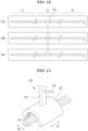
- FIG. 10 is a view showing a process of repairing and correcting the defective part 350 on the basis of an embodiment.
- FIG. 10 shows a first panoramic image 340a showing the defective part 350 in which the viscous fluid 40 is disconnected, a second panoramic image 340b showing a state in which the viscous fluid 40 is additionally dispensed to the defective part 350 by performing the repairing of the viscous fluid 40 at S40, and a third panoramic image 340c showing a state in which the shape of a viscous fluid 40 additionally dispensed to the defective part 350 is corrected according to the reference pattern by performing the correcting of the viscous fluid 40 at S50.
- the repairing of the viscous fluid 40 at S40 and the correcting of the viscous fluid 40 at S50 will be described with reference to FIG. 10 .
- the first panoramic image 340a may be obtained.
- the first panoramic image 340a it can be seen that a defect of disconnection exists in the viscous fluid 40 corresponding to the second section.
- the control module 500 controls the robot module 400 to locate the nozzle 210 of the dispenser module 100 at the defective part 350, and controls the dispenser module 100 to dispense a viscous fluid 40 to the defective part 350.
- the viscous fluid 40 has a shape different from the reference pattern, as shown in the second panoramic image 340b.
- the previously dispensed viscous fluid 40 has already begun to partially harden, and the viscous fluid 40 is viscous, and thus the viscous fluids 40 may overlap or have an unwanted shape in a portion of the defective part 350 or.
- the method for inspecting and repairing a dispensed viscous fluid on the basis of the embodiment may further include correcting the viscous fluid 40 by forming the shape of the viscous fluid 40 by discharging air to the viscous fluid 40 dispensed to the defective part 350 for repairing the defective part 350 at S50.
- the control module 500 may control the robot module 400 to position the correction module 200 on the defective part 350, and control the correction module 200 to additionally discharge air to the dispensed viscous fluid 40.
- the shape of the viscous fluid 40 may be modified by air discharged by the correction module 200 and be formed into a shape determined by the reference pattern. Referring to the third panoramic image 340c, it can be seen that the shape of the dispensed viscous fluid 40 having the defective part 350 is additionally corrected and is smoothly connected to the existing dispensed viscous fluid 40.
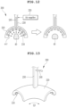
- FIG. 11 is a view showing the correction module 200 based on an embodiment.
- FIG. 12 is a view showing a process in which the correction module based on the embodiment forms the viscous fluid.
- the correction module 200 may include one nozzle or a plurality of nozzles 210 discharging air toward the viscous fluid 40, the body 220 fixing the nozzle 210 to be directed toward the viscous fluid 40, and an air supplier 230 supplying air to the nozzle 210 through an air line 240.
- the control module 500 may control whether the air supplier 230 outputs air and air output pressure of the air supplier 230 so that air discharged by the nozzle 210 changes the shape of the viscous fluid 40, and may control the robot module 400 to arrange the body 220 at a desired location.
- the nozzle 210 may be connected to the air supplier 230 through the air line 240.
- the nozzle 210 may discharge air to the viscous fluid 40.
- the nozzle 210 may include a plurality of nozzles.
- the cross section of the nozzle 210 may have various shapes, such as circular, square, or narrow and long slit shape.
- the nozzles 210 may be arranged in directions to discharge air toward the viscous fluid 40.
- the plurality of nozzles 210 may be arranged in an arcuate shape.
- the body 220 may perform the function of fixing the plurality of nozzles 210.
- the body 220 may be formed into various shapes according to the arrangement of the nozzles 210. When the plurality of nozzles 210 are arranged in an arch shape, one side of the body 220 facing the viscous fluid 40 may be formed in an arch shape so that the body 220 fixes the plurality of nozzles 210.
- the body 220 may have an arcuate cross section in the width direction WD of the viscous fluid 40 and may be formed into a long straight shape in the longitudinal direction LD of the viscous fluid 40 so that the plurality of nozzles 210 faces the viscous fluid 40.
- air discharged by the nozzles 210 is directed toward the center of the arch, and the cross section of the viscous fluid 40 may be formed to be close to a semicircle.
- a rod 250 may be connected to the body 220.
- the rod 250 may be connected to the robot module 400 or the dispenser module.
- the rod 250 may support the body 220 and the nozzle 210.
- the robot module 400 may adjust the position and direction of the rod 250 to locate the nozzle 210 of the correction module 200 on the defective part 350.
- the correcting of the viscous fluid 40 at S50 may include locating the correction module 200 at the defective part 350, and controlling whether the air supplier 230 outputs air and air output pressure of the air supplier 230 so that air discharged by the nozzle 210 changes the shape of the viscous fluid 40.
- the air line 240 is a path through which air flows.
- the air line 240 may be formed inside the body 220 and the rod 250.
- the air line 240 may be formed outside the body 220 and the rod 250.
- FIG. 11 shows a structure in which the air line 240 is formed inside the body 220 and the rod 250.
- the airline 240 may supply air to each of the plurality of nozzles 210. Air provided through the air line 240 from the air supplier 230 is discharged through the nozzle 210 to apply pressure to the viscous fluid 40.
- the control module 500 may control the air supplier 230 to adjust the timing of supplying air, timing of blocking air, air pressure, and an air flow rate, etc.
- FIG. 13 is a view showing a correction module 200 with a curved body 220 on the basis of an embodiment.
- the body 220 may have an arcuate cross section in the width direction WD of the viscous fluid 40 and may be formed into a long and curved shape in the longitudinal direction LD of the viscous fluid 40 so that the plurality of nozzles 210 faces the viscous fluid 40. As shown in FIG. 13 , the body 220 having a long and curved shape in the longitudinal direction LD of the viscous fluid 40 may be used when a defective part 350 is present in a curved portion. The degree of bending of the body 220 may be determined according to the reference pattern.
- the shape of the previous viscous fluid 40 does not change, but only the shape of an additionally dispensed viscous fluid 40 may be changed. Accordingly, the additionally dispensed viscous fluid 40 may be corrected to match the reference pattern.
- FIG. 14 is a view showing a correction module 200 with a transformable body 220 on the basis of an embodiment.
- the body 220 may include the plurality of sub-bodies 221, each of which has an arcuate cross section in the width direction WD of the viscous fluid 40 so that the plurality of nozzles 210 faces the viscous fluid 40, and joints 222 which connect the plurality of sub-bodies 221 to each other so that the plurality of sub-bodies 221 can be wholly transformed into a shape bent in the longitudinal direction LD of the viscous fluid 40.
- the control module 500 may control the joints 222 to correspond to the straight or curved portion of the reference pattern of the viscous fluid 40 so that air discharged by the nozzle 210 forms the viscous fluid 40 into a straight or curved line corresponding to the reference pattern.
- the body 220 may include the plurality of sub-bodies 221.
- the body 220 may include a first sub-body 221a to a fifth sub-body 221f.
- the number of the sub-bodies 221 or a distance between the sub-bodies 221 may be determined to correspond to the design of the reference pattern.
- the correcting of the viscous fluid 40 at S50 may include controlling the joints 222 to correspond to the straight or curved portion of the reference pattern of the viscous fluid 40 so that air discharged by the nozzle 210 forms the viscous fluid 40 into a straight or curved line corresponding to the reference pattern, locating the correction module 200 at the defective part 350, and controlling whether the air supplier 230 outputs air and air output pressure of the air supplier 230 so that air discharged by the nozzle 210 changes the shape of the viscous fluid 40.
- the sub-bodies 221 may hold the plurality of the nozzles 210.
- Each of the joints 222 may connect a sub-body 221 with a sub-body 221 and may be configured to adjust an angle between the sub-bodies under the control of the control module 500.
- the joint 222 may include a plurality of joints.
- the joint 222 may connect the first sub-body 221a with a second sub-body 222b, and another joint 222 may connect the second sub-body 222b with a third sub-body 222c.
- the joints 222 may change angles between the sub-bodies, by having a driving part including having motors, and gears, etc.
- the plurality of sub-bodies 221 may be used for a defective part 350 that occurs in a straight viscous fluid 40 equal to the shape of the body 220, which is long in the longitudinal direction LD of the viscous fluid 40 as shown in FIG 11 , and, which is equally.
- the plurality of sub-bodies 221 may be used for the defective part 350 present in a curved part of the viscous fluid 40 as shown in FIG. 12 .
- the control module 500 may control the joints 222 according to the shape of a reference pattern at a point at which a defective part 350 occurs and arrange the plurality of sub-bodies 221 to correspond to the reference pattern.
- FIG. 15 is a view showing the process of correcting a viscous fluid 40 according to the type of a defect by using a correction module 200 with nozzle groups 211 on the basis of an embodiment.
- the correction module 200 on the basis of the embodiment may include the nozzle groups 211.
- the plurality of nozzles 210 of the correction module 200 may be divided into two or more nozzle groups 211 which discharge air toward the viscous fluid 40 from various directions.
- the air supplier 230 may independently supply air to the air line 240 connected to each of the two or more nozzle groups 211.
- the control module 500 may independently control whether to output air supplied to the two or more nozzle groups 211 by the air supplier 230 and output pressure of the air according to the type of a defect of the viscous fluid 40.
- the correction module 200 may include a plurality of nozzle groups 211.
- the nozzle groups 211 may include a plurality of nozzles 210. Each of the nozzle groups 211 may receive air through the air line 240 from the air supplier 230.
- the number of air lines 240 may correspond to the number of nozzle groups 211.
- One or more air lines 240 may be connected to each nozzle group 211, and nozzles 210 included in one nozzle group 211 may discharge air in the same manner.
- FIG. 15 shows the correction module 200 including three nozzle groups 211a, 211b, and 211c.
- a first nozzle group 211a includes two nozzles 210 in a cross section
- a second nozzle group 211b includes five nozzles 210 in a cross section
- a third nozzle group 211c includes two nozzles 210 in a cross section.
- Two nozzles 210 of the first nozzle group 211a receive air from a first air line 240a, and whether to discharge the air and pressures at which to discharge the air may be the same between the two nozzles 210.
- Five nozzles 210 of the second nozzle group 211b receive air from a second air line 240b, and whether to discharge the air and pressures at which to discharge the air may be the same between the five nozzles 210.
- Two nozzles 210 of the third nozzle group 211c receive air from a third air line 240c, and whether to discharge the air and pressures at which to discharge the air may be the same between the two nozzles 210.
- the plurality of air lines 240a, 240b, and 240c may be connected to the air supplier 230.
- the air supplier 230 may independently control whether to discharge air and air discharge pressure for each of the air lines 240a, 240b, and 240c connected to the plurality of nozzle groups 211a, 211b, and 211c, respectively, on the basis of the control of the control module 500.
- the control module 500 may independently control whether to output air supplied to the two or more nozzle groups 211 by the air supplier 230 and output pressure of the air according to the type of a defect of the viscous fluid 40.
- FIG. 15 shows processes of correcting in Case 1 in which a 'break'-type defect occurred, and Case 2 in which a 'pressed'-type defect occurred.
- the defect type of the defective part is a type in which a part of the viscous fluid 40 is broken.
- the control module 500 may analyze the original images 310 to determine the type of the defective part and determine that a 'break'-type defect has occurred.
- the control module 500 may additionally apply the viscous fluid 40 to the defective part in the repairing of the viscous fluid 40 at S40.
- the viscous fluid 40 is additionally applied, the overlapping part 40a of the existing viscous fluid 40 and the newly applied viscous fluid 40 may occur.
- the control module 500 may control the air supplier 230 so that air is discharged from all of the first air line 240a, the second air line 240b, and the third air line 240c, and, as a result, air may be discharged from all of the first nozzle group 211a, the second nozzle group 211b, and the third nozzle group 211c to correct the overlapping part 40a of the viscous fluid 40.
- the viscous fluid 40 may have a desired shape as in 'after correction' in FIG. 15 .
- a defective type of the defective part is a type in which a part of the dispensed viscous fluid 40 has a pressed form 40b.
- the control module 500 may analyze original images to determine the type of the defective part as the occurrence of a'pressed'-type defect.
- the control module 500 may control the air supplier 230 so that air is discharged only from a portion of the nozzle group 211. In the controlling of whether the air supplier 230 outputs air and the air output pressure thereof (see during correction in Case 2 of FIG.
- the control module 500 may control the air supplier 230 so that the first air line 240a and the third air line 240c discharge air, and, as a result, air may be discharged from the first nozzle group 211a and the third nozzle group 211c.
- the first nozzle group 211a and the third nozzle group 211c are nozzle groups 211 located on opposite sides of the pressed part of the viscous fluid 40. Accordingly, air discharged from the first nozzle group 211a and the third nozzle group 211c may apply force to each of the opposite sides of the pressed viscous fluid 40 so that the pressed viscous fluid 40 can be corrected to an unpressed state.
- the viscous fluid 40 can have a desired shape.
- Case 1 and Case 2 illustrate some of various types of defects.
- various types of defects may exist.
- the control module 500 may control air to be discharged from a nozzle group 211 located in a direction necessary to correct a defect.
- Cases 1 and 2 show the correction module 200 with three nozzle groups 211.
- a correction module 200 with various numbers and arrangements of nozzle groups 211 may be implemented.
- the control module 500 may control the various numbers and arrangements of nozzle groups 211 to correct a viscous fluid 40 of a defective part.
Landscapes
- Engineering & Computer Science (AREA)
- Chemical & Material Sciences (AREA)
- Physics & Mathematics (AREA)
- General Physics & Mathematics (AREA)
- Computer Vision & Pattern Recognition (AREA)
- Chemical Kinetics & Catalysis (AREA)
- General Chemical & Material Sciences (AREA)
- Electrochemistry (AREA)
- Quality & Reliability (AREA)
- Theoretical Computer Science (AREA)
- Pathology (AREA)
- Immunology (AREA)
- General Health & Medical Sciences (AREA)
- Biochemistry (AREA)
- Analytical Chemistry (AREA)
- Manufacturing & Machinery (AREA)
- Life Sciences & Earth Sciences (AREA)
- Health & Medical Sciences (AREA)
- Signal Processing (AREA)
- Coating Apparatus (AREA)
Abstract
Description
- The disclosed technology relates to an apparatus and a method for inspecting and repairing a dispensed viscous fluid.
- Thermal adhesive may be used in the process of manufacturing a battery module. Thermal adhesive, which is a viscous fluid, may be applied to the battery module by a dispenser. The shape of thermal adhesive applied to the battery module may affect the cooling performance of the battery module. When impact or vibration is applied to the battery module, parts to which the thermal adhesive is poorly applied may be damaged. Accordingly, it is necessary to check whether the thermal adhesive satisfies a predetermined application quality.
- The disclosed technology provides an apparatus and a method for inspecting and repairing a dispensed viscous fluid.
- In an aspect of the disclosed technology, there is provided an apparatus for inspecting and repairing a dispensed viscous fluid according to the disclosed technology, the apparatus including: a dispenser module dispensing a viscous fluid on a workpiece; a vision module generating original images by photographing the viscous fluid dispensed on the workpiece; a robot module moving the dispenser module and the vision module through predetermined paths, respectively; and a control module determining whether a defective part exists in the dispensed viscous fluid by analyzing the original images and controlling the dispenser module and the robot module to dispense a viscous fluid to a defective part when the defective part exists.
- On the basis of an embodiment, the control module may generate sampling images by extracting some of the original images generated by being photographed in real time by the vision module by considering a moving distance of the robot module and a shooting interval of the vision module, may generate stitching images by connecting the sampling images to each other on a basis of a shape of the viscous fluid shown in each of the sampling images, may generate a panoramic image by connecting the stitching images to each other, and may determine in real time whether a defect exists in the viscous fluid shown in the panoramic image.
- The apparatus for inspecting and repairing a dispensed viscous fluid on the basis of an embodiment may further include a correction module which is moved by the robot module and forms a shape of the viscous fluid by discharging air to the viscous fluid dispensed to the defective part for repairing the defective part on a basis of control of the control module.
- On the basis of an embodiment, the correction module may include: one nozzle or a plurality of nozzles discharging air toward the viscous fluid; a body fixing the nozzle to be directed toward the viscous fluid; and an air supplier supplying air to the nozzle through an air line, wherein the control module may control whether the air supplier outputs air and air output pressure of the air supplier so that air discharged by the nozzle changes a shape of the viscous fluid, and may control the robot module to arrange the body at a desired position.
- On the basis of an embodiment, the body may have an arcuate cross section in a width direction of the viscous fluid and may be formed into a long straight shape in a longitudinal direction of the viscous fluid so that the plurality of nozzles faces the viscous fluid.
- On the basis of an embodiment, the body may include: a plurality of sub-bodies, each of which has an arcuate cross section in a width direction of the viscous fluid so that the plurality of nozzles faces the viscous fluid; and joints connecting the plurality of sub-bodies to each other so that the plurality of sub-bodies is wholly transformed into a shape bent in the longitudinal direction of the viscous fluid, wherein the control module may control the joints to correspond to a straight or curved portion of a reference pattern of the viscous fluid so that air discharged by the nozzle forms the viscous fluid into a straight or curved line corresponding to the reference pattern.
- On the basis of an embodiment, the body may have an arcuate cross section in a width direction of the viscous fluid and may be formed into a long and curved shape in the longitudinal direction of the viscous fluid so that the plurality of nozzles faces the viscous fluid.
- On the basis of an embodiment, the plurality of nozzles may be divided into two or more nozzle groups which discharge air toward the viscous fluid from various directions, the air supplier may independently supply air to the air line connected to each of the two or more nozzle groups, and the control module may independently control whether to output air supplied to the two or more nozzle groups by the air supplier and output pressure of the air according to a type of a defect of the viscous fluid.
- There is provided a method for inspecting and repairing a dispensed viscous fluid according to the disclosed technology, the method including: dispensing a viscous fluid on a workpiece by a dispenser module moved by a robot module; generating original images by a vision module photographing the dispensed viscous fluid on the workpiece; inspecting the dispensed viscous fluid to see whether a defective part exists in the dispensed viscous fluid by a control module analyzing the original images; and repairing the viscous fluid by the control module controlling the dispenser module and the robot module to dispense a viscous fluid to a defective part when the defective part exists in the dispensed viscous fluid.
- On the basis of an embodiment, the inspecting may include: generating sampling images by extracting some of the original images generated by the vision module by considering the moving distance of the robot module and the shooting interval of the vision module; generating stitching images by connecting the sampling images to each other on a basis of a shape of the viscous fluid shown in the sampling images; generating a panoramic image by connecting the stitching images to each other; and determining whether a defect exists in the viscous fluid by comparing a shape of the viscous fluid shown in the panoramic image with a reference pattern, wherein the inspecting may be performed in real time.
- The method for inspecting and repairing a dispensed viscous fluid on the basis of an embodiment may further include correcting the viscous fluid by forming a shape of the viscous fluid by discharging air to the viscous fluid dispensed to the defective part by using a correction module for repairing the defective part.
- On the basis of an embodiment, the correction module include: the one nozzle or the plurality of nozzles discharging air toward the viscous fluid; the body fixing the nozzle to be directed toward the viscous fluid; and the air supplier supplying air to the nozzle through the air line, wherein the correcting of the viscous fluid may include: locating the correction module at the defective part; and controlling whether the air supplier outputs air and air output pressure of the air supplier so that air discharged by the nozzle changes the shape of the viscous fluid.
- On the basis of an embodiment, the body may include: the plurality of sub-bodies, each of which has an arcuate cross section in a width direction of the viscous fluid so that the plurality of nozzles faces the viscous fluid; and the joints connecting the plurality of sub-bodies to each other so that the plurality of sub-bodies is wholly transformed into a shape bent in the longitudinal direction of the viscous fluid, wherein the correcting of the viscous fluid may include: controlling the joints to correspond to a straight or curved portion of the reference pattern of the viscous fluid so that air discharged by the nozzle forms the viscous fluid into a straight or curved line corresponding to the reference pattern; performing the locating of the correction module at the defective part; and performing the controlling of whether the air supplier outputs air and air output pressure of the air supplier so that air discharged by the nozzle changes the shape of the viscous fluid.
- On the basis of an embodiment, the plurality of nozzles may be divided into two or more nozzle groups which discharge air toward the viscous fluid from various directions, the air supplier may independently supply air to the air line connected to each of the two or more nozzle groups, and in the controlling of whether the air supplier outputs air and air output pressure of the air supplier, the control module may independently control whether to output air supplied to the two or more nozzle groups by the air supplier and output pressure of the air according to a type of a defect of the viscous fluid.
- The features and advantages of the disclosed technology will become more apparent through the following detailed description based on the accompanying drawings.
- Prior to the description, terms or words used in this specification and claims should not be construed in their usual, dictionary meaning, and on the basis of the principle that the inventor may appropriately define the concept of the terms in order to explain his or her invention in the best way, the terms should be interpreted as having meaning and concept consistent with the technical idea of the disclosed technology.
- According to the disclosed technology, the quality of a dispensed viscous fluid can be inspected in real time, a disconnected part of a viscous fluid can be repaired, and the shape of the viscous fluid in the repaired part can be formed, thereby improving dispensing quality.
-
-
FIG. 1 is a view showing a battery cell on the basis of an embodiment. -
FIG. 2 is a cross-sectional view taken along line A-A' ofFIG. 1 . -
FIG. 3 is a view showing a battery module manufactured by coupling the battery cell and a housing to each other by a dispensed viscous fluid on the basis of an embodiment. -
FIG. 4 is a view snowing the combination of the dispensed viscous fluid, the battery cell, a lower cover on the basis of an embodiment. -
FIG. 5 is a view showing a state in which an apparatus for inspecting and repairing a dispensed viscous fluid on the basis of an embodiment dispenses a viscous fluid. -
FIG. 6 is a block diagram showing the apparatus for inspecting and repairing a dispensed viscous fluid on the basis of an embodiment. -
FIG. 7 is a flowchart showing a method for inspecting and repairing a dispensed viscous fluid on the basis of an embodiment. -
FIG. 8 is a view showing a dispensed viscous fluid and an imaging area on a workpiece on the basis of an embodiment. -
FIG. 9 is a view showing original images, sampling images, stitching images, and a panoramic image on the basis of an embodiment. -
FIG. 10 is a view showing a process of repairing and correcting a defective part on the basis of an embodiment. -
FIG. 11 is a view showing a correction module based on an embodiment. -
FIG. 12 is a view showing a process in which the correction module based on the embodiment forms the viscous fluid. -
FIG. 13 is a view showing a correction module with a curved body on the basis of an embodiment. -
FIG. 14 is a view showing a correction module with a transformable body on the basis of an embodiment. -
FIG. 15 is a view showing the process of correcting a viscous fluid according to the type of a defect by using a correction module with nozzle groups on the basis of an embodiment. - The objectives, advantages, and features of the disclosed technology will become more apparent from the following detailed description and preferred embodiments in conjunction with the accompanying drawings, but the disclosed technology is not necessarily limited thereto. Additionally, when explaining the disclosed technology, if it is determined that a detailed description of the related known technology may unnecessarily obscure the gist of the disclosed technology, detailed description thereof is omitted.
- In assigning reference numerals to components in the drawings, it should be noted that identical components are assigned the same reference numerals as much as possible even if they are shown in different drawings, and similar components are assigned similar reference numerals.
- Terms used to describe an embodiment of the disclosed technology are not intended to limit the disclosed technology. It should be noted that singular expressions include plural expressions unless the context clearly dictates otherwise.
- The drawings may be schematic or exaggerated to illustrate embodiments.
- In this document, expressions such as "have", "may have", "includes", or "may include" refer to the existence of the corresponding features (e.g., a numerical value, function, operation, or component such as a part) and does not rule out the existence of additional features.
- Terms such as "one", "other", "another", "first", and "second", etc. are used to separate one component from another. The components are used for distinction, and the components are not limited by the above terms.
- It should be understood that directional terms such as up, down, left, right, x-axis, y-axis, and z-axis, etc. are used for descriptive purposes only and may be expressed differently depending on the position of an observer or the position of an object.
- Embodiments described herein and the accompanying drawings are not intended to limit the disclosed technology to any particular embodiment. The disclosed technology is to be understood to include various modifications, equivalents, and/or alternatives of the embodiments.
- Hereinafter, an embodiment of the disclosed technology will be described in detail with reference to the accompanying drawings.
-
FIG. 1 is a view showing a battery cell on the basis of an embodiment.FIG. 2 is a cross-sectional view taken along line A-A' ofFIG. 1 .FIG. 3 is a view showing abattery module 1 manufactured by coupling thebattery cell 10 and ahousing 20 to each other by a dispensedviscous fluid 40 on the basis of an embodiment.FIG. 4 is a view snowing the combination of the dispensedviscous fluid 40, thebattery cell 10, and alower cover 21 on the basis of an embodiment.FIG. 4 shows thebattery module 1, other components of which are omitted. - The
battery cell 10 may be formed so that anexterior material 13 surrounds an electrode assembly 11from which anelectrode tab 12 is pulled out. Theelectrode assembly 11 may include a positive electrode material, a negative electrode material, and a separator, and theelectrode tab 12 may be connected to each of the positive electrode material and the negative electrode material. Theexterior material 13 may be a film, an aluminum layer of which has lower and upper parts coated with an electrical insulating material. - The
battery cell 10 may be formed in a pouch type by having oneexterior material 13 formed therein to store theelectrode assembly 11 therein so that one surface of the battery cell does not have a sealingpart 14 and each of three surfaces thereof have the sealingpart 14. The sealingpart 14 is a part on which the facing parts of theexterior material 13 is joined by a thermal, physical, or chemical method. For example, in thebattery cell 10 ofFIGS. 1 and2 , afirst surface 15a and asecond surface 15b become receiving parts due to the forming of theexterior material 13, athird surface 15c, which is a part on which theexterior material 13 is folded, has no sealingpart 14, and each of afourth surface 15d, afifth surface 15e, asixth surface 15f may have the sealingpart 14. Theelectrode tab 12 may be pulled out through thefourth surface 15d and thesixth surface 15f. - The
battery module 1 may be manufactured to have structure in which a plurality ofbattery cells 10 is stored in thehousing 20. Thehousing 20 and thebattery cell 10 may be joined by theviscous fluid 40 such as adhesive. Theviscous fluid 40 may include various components and is a viscous fluid. Theviscous fluid 40 may include thermal adhesive. Theviscous fluid 40 may include a two-component adhesive in which a resin with a cooling function and a hardener for physical fixation are mixed with each other. Theviscous fluid 40 hardens between thebattery cell 10 and thehousing 20 to fix thebattery cell 10 and thehousing 20 to each other. - The
housing 20 may include anupper cover 22, thelower cover 21, afirst side cover 23, asecond side cover 24, afront cover 25, and arear cover 26. The covers may be connected to each other or formed integrally to constitute thehousing 20.FIG. 3 shows thebattery module 1 of structure in which a plurality ofbattery cells 10 is stored in a storage space defined by combining thelower cover 21, thefirst side cover 23, thesecond side cover 24, thefront cover 25, and therear cover 26. Thebattery cell 10 and thelower cover 21 may be fixed to each other by contacting thebattery cell 10 on thelower cover 21 on which theviscous fluid 40 is dispensed. - In addition to the structure of the
battery cell 10 shown inFIGS. 1 and2 , theapparatus 2 for inspecting and repairing a dispensed viscous fluid on the basis of the embodiment may be used even when manufacturing a battery module including a battery cell having structure in which twoelectrode tabs 12 are pulled out through one surface, a battery cell having structure in which sealingparts 14 are formed on four surfaces by using twoexterior materials 13, or a battery cell having structure in which a plurality ofelectrode tabs 12 having the same polarities is arranged on one surface. - As shown in
FIG. 4 , thethird surface 15c of thebattery cell 10 may be in contact with the dispensedviscous fluid 40 on thelower cover 21. In a process in which theviscous fluid 40 is dispensed, a defect in which theviscous fluid 40 is not dispensed in some areas or dispensed in an insufficient amount may occur. Such a defect may cause separation of thebattery cell 10 from thelower cover 21, and may form a gap between thebattery cell 10 and thelower cover 21, making it difficult for heat of thebattery cell 10 to be discharged to thelower cover 21. - The
viscous fluid 40, such as thermal adhesive, begins to harden from a moment at which theviscous fluid 40 is dispensed, so the dispensing and inspection of theviscous fluid 40 are required to be performed simultaneously. Theapparatus 2 for inspecting and repairing a dispensed viscous fluid on the basis of an embodiment may inspect theviscous fluid 40 immediately after dispensing theviscous fluid 40, additionally dispense the viscous fluid to adefective part 350 when thedefective part 350 is detected, and may repair thedefective part 350. Accordingly, theapparatus 2 may repair thedefective part 350 before theviscous fluid 40 hardens. - Furthermore, the
apparatus 2 for inspecting and repairing a dispensed viscous fluid on the basis of the embodiment may inspect theviscous fluid 40 immediately after dispensing theviscous fluid 40, dispense additionally theviscous fluid 40 to thedefective part 350 when thedefective part 350 is detected, and may additionally form the shape of the dispensedviscous fluid 40 by using acorrection module 200. Theviscous fluid 40 begins to harden immediately after dispensed and has high viscosity, so the shape of theviscous fluid 40 according to a reference pattern cannot be formed simply by additionally dispensing theviscous fluid 40 to thedefective part 350. Accordingly, on the basis of the embodiment, by using thecorrection module 200, the shape of the additionally dispensedviscous fluid 40 can be formed according to a reference pattern, thereby improving dispensing quality. -
FIG. 5 is a view showing a state in which an apparatus for inspecting and repairing a dispensedviscous fluid 40 on the basis of an embodiment dispenses theviscous fluid 40. InFIG. 5 , control signals that acontrol module 500 applies adispenser module 100, thecorrection module 200, avision module 300, and arobot module 400 are indicated with dotted lines.FIG. 6 is a block diagram showing the apparatus for inspecting and repairing a dispensedviscous fluid 40 on the basis of an embodiment. - The
apparatus 2 for inspecting and repairing a dispensed viscous fluid on the basis of an embodiment may include: thedispenser module 100 dispensing theviscous fluid 40 to aworkpiece 30; thevision module 300 generatingoriginal images 310 by photographing the dispensedviscous fluid 40 on theworkpiece 30; therobot module 400 moving thedispenser module 100 and thevision module 300 through predetermined paths, respectively; and thecontrol module 500 determining whether thedefective part 350 exists in the dispensedviscous fluid 40 by analyzing theoriginal images 310 and controlling thedispenser module 100 and therobot module 400 so as to dispense theviscous fluid 40 to thedefective part 350 when thedefective part 350 exists. - The
workpiece 30 may be thebattery module 1 or a component of the battery pack. Theworkpiece 30 may be the lower cover of thehousing 20 of thebattery module 1. Theworkpiece 30 may be a battery cell or the upper cover. - The
dispenser module 100 can dispense theviscous fluid 40 to theworkpiece 30. Thedispenser module 100 may include a resin tank, a hardener tank, a pump, thenozzle 210, a valve, and a mixer required to dispense theviscous fluid 40. In this specification, a detailed description of the components that thedispenser module 100 that dispenses theviscous fluid 40 may include is omitted. According to the control of thecontrol module 500, thedispenser module 100 may dispense theviscous fluid 40 to theworkpiece 30 according to a reference pattern. Thedispenser module 100 may additionally dispense theviscous fluid 40 to thedefective part 350 according to the control of thecontrol module 500. - On the basis of the control of the
control module 500, therobot module 400 may move thedispenser module 100 according to a reference pattern. Therobot module 400 may position thenozzle 210 of thedispenser module 100 at a predetermined point with respect to theworkpiece 30 and may move thenozzle 210 according to the reference pattern. Therobot module 400 may include a robot arm that can operate in six-axis directions. Therobot module 400 may include a device that moves thenozzle 210 of thedispenser module 100 along X, Y, and Z axes. - Due to the viscous nature of the
viscous fluid 40, the shape of theviscous fluid 40 dispensed on theworkpiece 30 may vary depending on the amount and pressure of the fluid dispensed by thedispenser module 100 and the speed and path of thedispenser module 100 moved by therobot module 400. Thecontrol module 500 may integrally control thedispenser module 100 and therobot module 400 so that theviscous fluid 40 is dispensed according to a reference pattern. - The
vision module 300 may generate theoriginal images 310 by photographing the dispensedviscous fluid 40. Thevision module 300 may include one or more cameras. Thevision module 300 may generate theoriginal images 310 and provide theoriginal images 310 to thecontrol module 500. Thevision module 300 may generate theoriginal images 310 in black and white, an RGB color, or infrared depending on the type of a camera. Thevision module 300 may be moved by therobot module 400 so that thevision module 300 moves along theviscous fluid 40 that thedispenser module 100 dispenses. Thevision module 300 is physically connected to thedispenser module 100 and may photograph the dispensedviscous fluid 40 according to a path along which therobot module 400 moves thedispenser module 100. Therobot module 400 may move thevision module 300 independently of thedispenser module 100. - The
control module 500 may analyze theoriginal images 310 received from thevision module 300 to determine whether thedefective part 350 exists in the dispensedviscous fluid 40. Thedefective part 350 is a part that is dispensed differently from the reference pattern. For example, thedefective part 350 may include a part in which a pattern is broken due to the dispensedviscous fluid 40 being insufficient in amount or theviscous fluid 40 not being dispensed to a specific part. - The
control module 500 may generatesampling images 320 by extracting some of theoriginal images 310 generated by being photographed in real time by thevision module 300 by considering the moving distance of therobot module 400 and the shooting interval of the vision module, may generatestitching images 330 by connecting thesampling images 320 to each other on the basis of the shape of theviscous fluid 40 shown in each of thesampling images 320, may generate apanoramic image 340 by connecting thestitching images 330 to each other, and may determine in real time whether a defect exists in theviscous fluid 40 shown in thepanoramic image 340. - The
original images 310 are images generated by thevision module 300. Considering a distance by which therobot module 400 moves thevision module 300 and an interval at which thevision module 300 photographs theviscous fluid 40, portions of the plurality oforiginal images 310 may be photographed to overlap. - The
sampling images 320 are an extraction of a portion of theoriginal images 310. Thecontrol module 500 may generate thesampling images 320 by extracting a portion of theoriginal images 310 so that overlapping portions of theoriginal images 310 and theviscous fluid 40 are included. - The
stitching images 330 may be generated by connecting the plurality ofsampling images 320 to each other in order. Thecontrol module 500 may generate thestitching images 330 by performing stitching for connecting thesampling images 320 to match the shape of theviscous fluid 40 shown in thesampling image 320 of the previous order according to the shapes of theviscous fluid 40 shown at borders between the samplingimages 320. - The
panoramic image 340 is formed by performing image processing for inspecting thedefective part 350 after connecting each of thestitching images 330 to each other so that thestitching image 330 has a predetermined length. Thecontrol module 500 may generate a long image in a longitudinal direction LD of theviscous fluid 40 by continuously connecting thestitching images 330. Thecontrol module 500 may binarize the image on the basis of color or shade difference between the workpiece 30 and theviscous fluid 40. - The
control module 500 may recognize a part of thepanoramic image 340 in which theviscous fluid 40 is cut off, or thickness is thinner than a predetermined value and may determine the part as thedefective part 350. Thecontrol module 500 may control thedispenser module 100 and therobot module 400 to dispense theviscous fluid 40 to thedefective part 350 when thedefective part 350 exists. Thecontrol module 500 may repair thedefective part 350 by additionally dispensing theviscous fluid 40 to thedefective part 350. - The
apparatus 2 for inspecting and repairing a dispensed viscous fluid on the basis of the embodiment may further include thecorrection module 200 which is moved by therobot module 400 and forms the shape of theviscous fluid 40 by discharging air to theviscous fluid 40 dispensed to thedefective part 350 for repairing thedefective part 350 on the basis of the control of thecontrol module 500. - The
correction module 200 may discharge air to form theviscous fluid 40 into a desired shape. Thecorrection module 200 may be moved by therobot module 400. Thecorrection module 200, thevision module 300, and the dispenser module may be moved together or separately by therobot module 400. Since theviscous fluid 40 is viscous, it is not suitable for theviscous fluid 40 to be formed through physical contact. Accordingly, in the embodiment, thecorrection module 200, which discharges air, may change theviscous fluid 40 into a desired shape by using force applied to theviscous fluid 40 by the air. Thecontrol module 500 may control pressure at which thecorrection module 200 discharges air to theviscous fluid 40, the amount of air, the air discharge start time, the air discharge end time, and the direction of thenozzle 210 that sprays air. The specific shape and control method of thecorrection module 200 will be described later. - The
control module 500 may include aprocessor 510 and astorage 520 which is communicatively connected to theprocessor 510 and stores program codes. Thecontrol module 500 may further include an Input/output interface 530 that is communicatively connected to theprocessor 510 and receives a user input and provides information to the user. Thecontrol module 500 may further include aCommunicator 540 which is communicatively connected to theprocessor 510 and connected to a wired or wireless network to transmit and receive data. - The
processor 510 may include a CPU, GPU, PLC, or other elements capable of performing various information processing functions. Theprocessor 510 may perform a method for inspecting and repairing a dispensed viscous fluid on the basis of the embodiment by reading and executing program codes stored in thestorage 520. - The
storage 520 may include memory, a hard disk, a magnetic tape, or various data storage media. Thestorage 520 may store a program code written to perform the method for inspecting and repairing a dispensed viscous fluid on the basis of the embodiment, the reference pattern, a defect judgment standard, and data required to perform the method for inspecting and repairing a dispensed viscous fluid. - The Input/
output interface 530 may include an input device such as a touchpad, a mouse, a keyboard, a button, and a lever to receive user commands, and an output device such as a display, a touch screen, a speaker, a printer, and a light emitter to provide information to a user. - The
Communicator 540 may use various communication methods to transmit and receive data by being connected to a wired or wireless network. TheCommunicator 540 may use WAN, LAN, ethernet, 5G, 6G, LTE, wi-fi, bluetooth, or known communication methods. -
FIG. 7 is a flowchart showing a method for inspecting and repairing the dispensedviscous fluid 40 on the basis of an embodiment.FIG. 8 is a view showing the dispensedviscous fluid 40 and an imaging area on theworkpiece 30 on the basis of an embodiment. An enlarged view taken along line B-B' ofFIG. 8 shows across-sectional shape 40C of theviscous fluid 40. The following description will be made with reference toFIGS. 7 and8 . - The method for inspecting and repairing a dispensed viscous fluid on the basis of the embodiment may include: dispensing a
viscous fluid 40 on theworkpiece 30 by thedispenser module 100 moved by therobot module 400 at S10; generating theoriginal images 310 by thevision module 300 photographing the dispensedviscous fluid 40 on theworkpiece 30 at S20, inspecting the dispensedviscous fluid 40 to see whether thedefective part 350 exists in the dispensedviscous fluid 40 by thecontrol module 500 analyzing theoriginal images 310 at S30; and repairing theviscous fluid 40 by thecontrol module 500 controlling thedispenser module 100 and therobot module 400 so that aviscous fluid 40 is dispensed to adefective part 350 when thedefective part 350 exists in the dispensedviscous fluid 40 at S40. - The dispensing of the
viscous fluid 40 at S10 is a process in which therobot module 400 moves thedispenser module 100 according to a reference pattern and thedispenser module 100 dispenses theviscous fluid 40 on the basis of the control of thecontrol module 500. The reference pattern may be stored in thestorage 520. The reference pattern may be determined according to the design of theworkpiece 30. - Referring to
FIG. 8 , the reference pattern may include information about the coordinates of the dispensing start point (x1, y1), dispensing midpoint (x2, y2), and dispensing end point (x8, y8) of theviscous fluid 40, a pattern shape according to the coordinates, alength 40L,width 40W, andheight 40H, of theviscous fluid 40, and thecross-sectional shape 40C. - When the dispensing of the
viscous fluid 40 at S10 is performed, theviscous fluid 40 is dispensed on theworkpiece 30 according to the reference pattern. While the dispensing of theviscous fluid 40 at S10 is performed, thevision module 300 may simultaneously perform the generating of theoriginal images 310 by photographing the dispensedviscous fluid 40 at S20. - The generating of the
original images 310 at S20 is a process in which thevision module 300 photographs the dispensedviscous fluid 40 on theworkpiece 30 and provides the generatedoriginal images 310 to thecontrol module 500. Thevision module 300 may photograph the dispensedviscous fluid 40 according to the shape of the reference pattern. Thevision module 300 may photograph the dispensedviscous fluid 40 while moving along a path taken by thedispenser module 100. The generating of theoriginal images 310 at S20 may be performed in real time while theviscous fluid 40 is dispensed. Areas corresponding to theoriginal images 310 generated by thevision module 300 are indicated by dotted boxes inFIG. 8 . Thevision module 300 may generate theoriginal images 310 by photographing theviscous fluid 40 included in each of sections G1, G2, G3, and G4. The sections, which are parts of theviscous fluid 40 corresponding to parts at which thebattery cells 10 and the workpiece 30 (for example, the lower cover) are connected to each other, are areas to determine whether thedefective part 350 exists. - The
vision module 300 may photograph the first section G1 and may generate a firstoriginal image 310a, a secondoriginal image 310b, and a thirdoriginal image 310c. According to a moving speed of therobot module 400 and a shooting interval of thevision module 300, thevision module 300 may photograph twooriginal images 310 taken in sequence so that the original images partially overlap each other. Since theoriginal images 310 are photographed to partially overlap, a defect that may exist at a boundary between theoriginal images 310 may be recognized. Thevision module 300 may provide the plurality of generatedoriginal images 310 to thecontrol module 500 in order. The plurality oforiginal images 310 may be stored in thestorage 520. -
FIG. 9 is a view showing original images,sampling images 320,stitching images 330, and a panoramic image on the basis of an embodiment. - The inspecting of the viscous fluid at S30 may include generating the
sampling images 320 by extracting some of theoriginal images 310 generated by thevision module 300 by considering the moving distance of therobot module 400 and the shooting interval of the vision module at S31, generating thestitching images 330 by connecting thesampling images 320 to each other on the basis of the shape of theviscous fluid 40 shown in thesampling images 320 at S32, generating thepanoramic image 340 by connecting thestitching images 330 to each other at S33, and determining whether a defect exists in theviscous fluid 40 by comparing the shape of theviscous fluid 40 shown in thepanoramic image 340 with the reference pattern at S34. The inspecting of the viscous fluid may be performed in real time. Since the inspecting of the viscous fluid at S30 is performed in real time, it is possible to immediately determine whether the defective part exists in theviscous fluid 40. Accordingly, theviscous fluid 40 may be repaired and corrected before theviscous fluid 40 is completely hardened. - The generating of the
sampling images 320 at S31 is the process of extracting a portion of theoriginal images 310. A control part may extract one ormore sampling images 320 from theoriginal images 310. Thesampling images 320 may be extracted so that some of the sampling images overlap with each other. For description,FIG. 9 illustrates that twosampling images 320 are extracted from oneoriginal image 310. Afirst sampling image 320a and asecond sampling image 320b may be extracted from the firstoriginal images 310a, athird sampling images 320c and afourth sampling image 320d may be extracted from the secondoriginal images 310b, and afifth sampling image 320e and asixth sampling image 320f may be extracted from the thirdoriginal images 310c. - The generating of the
stitching images 330 at S32 is the process of connecting the plurality ofsampling images 320 to each other. Stitching is a technique that naturally connects a plurality of images to each other. Thecontrol module 500 may connect a plurality ofsampling images 320 to each other by overlapping the sampling images in order on the basis of the width of theviscous fluid 40 that appears at the boundary of thesampling images 320. The pixels of aviscous fluid 40 on the left border of thesecond sampling image 320b can be connected to match the pixels of aviscous fluid 40 shown on the right side of thefirst sampling image 320a. In a process in which therobot module 400 moves thevision module 300, theviscous fluid 40 does not appear in the same position in each of alloriginal images 310 due to the impact of vibration. Accordingly, thesampling images 320 are generated by extracting some of theoriginal images 310, and a continuous image of theviscous fluid 40 may be obtained through stitching of connecting the sampling images on the basis of theviscous fluid 40 shown in thesampling images 320. - The generating of the
panoramic image 340 at S33 is a process of connecting thestitching images 330 to generate a long image in the longitudinal direction LD of theviscous fluid 40 and performing image processing such as binarization to determine thedefective part 350. The following description will be made with reference toFIGS. 8 and9 . The dispensedviscous fluid 40 may be divided into sections according to the shape of a pattern thereof. InFIG. 8 , there is a first section G1 to fourth section G4 in which theviscous fluid 40 is dispensed long, and inFIG. 9 , afirst stitching image 330a representing theviscous fluid 40 of the first section G1, asecond stitching image 330b representing theviscous fluid 40 of the second section G2, and athird stitching image 330c representing theviscous fluid 40 of the third section G3 may be connected to each other to form onepanoramic image 340. Thecontrol module 500 may connect thestitching images 330 to each other and perform binarization processing. Thepanoramic image 340 is binarized to distinguish a color value of theviscous fluid 40 from a color value except for theviscous fluid 40. The binarizedpanoramic image 340 may clearly show the boundary of theviscous fluid 40 as illustrated inFIG. 9 . - The determining of whether a defect exists in the viscous fluid at S34 is a process of determining whether a defect exists by comparing the
viscous fluid 40 shown in thepanoramic image 340 with the reference pattern. Thecontrol module 500 may determine whether a defect exists by comparing the width of the reference pattern with the width of theviscous fluid 40 of thepanoramic image 340. For example, when a part of theviscous fluid 40 of thepanoramic image 340 is disconnected, or a part thereof has a width smaller than a predetermined standard width compared to the reference pattern, the corresponding part may be determined to be defective. - The following description will be made by referring back to
FIG. 7 . - The inspecting of the
viscous fluid 40 at S30, when thedefective part 350 exists in the dispensedviscous fluid 40, the repairing of theviscous fluid 40 at S40 may be performed. - The repairing of the
viscous fluid 40 at S40 is a process of filling a gap of thedefective part 350 by locating thenozzle 210 of thedispenser module 100 at a part determined to be defective and additionally dispensing theviscous fluid 40 thereto. The repairing of theviscous fluid 40 at S40 may be performed after the dispensing of theviscous fluid 40 at S10 has been completely performed according to the reference pattern. Alternatively, when thedefective part 350 is determined to exist in the inspecting of the dispensedviscous fluid 40 at S30, the dispensing of theviscous fluid 40 at S10 may stop and the repairing of theviscous fluid 40 at S40 may be performed. Alternatively, aft4er the dispensing of theviscous fluid 40 at S10 is performed according to a reference pattern corresponding to the sections G1 to G4 shown inFIG. 8 , the repairing of theviscous fluid 40 at S40 may be performed. That is, the repairing of theviscous fluid 40 at S40 may be performed for each designated section of a reference pattern. -
FIG. 10 is a view showing a process of repairing and correcting thedefective part 350 on the basis of an embodiment.FIG. 10 shows a firstpanoramic image 340a showing thedefective part 350 in which theviscous fluid 40 is disconnected, a secondpanoramic image 340b showing a state in which theviscous fluid 40 is additionally dispensed to thedefective part 350 by performing the repairing of theviscous fluid 40 at S40, and a thirdpanoramic image 340c showing a state in which the shape of aviscous fluid 40 additionally dispensed to thedefective part 350 is corrected according to the reference pattern by performing the correcting of theviscous fluid 40 at S50. The repairing of theviscous fluid 40 at S40 and the correcting of theviscous fluid 40 at S50 will be described with reference toFIG. 10 . - When the dispensing of the
viscous fluid 40 at S10, the generating of theoriginal images 310 at S20, and the inspecting of theviscous fluid 40 at S30 are performed, the firstpanoramic image 340a may be obtained. In the firstpanoramic image 340a, it can be seen that a defect of disconnection exists in theviscous fluid 40 corresponding to the second section. - In the repairing of the
viscous fluid 40 at S40, thecontrol module 500 controls therobot module 400 to locate thenozzle 210 of thedispenser module 100 at thedefective part 350, and controls thedispenser module 100 to dispense aviscous fluid 40 to thedefective part 350. When a predetermined amount of theviscous fluid 40 is dispensed to thedefective part 350, theviscous fluid 40 has a shape different from the reference pattern, as shown in the secondpanoramic image 340b. The previously dispensedviscous fluid 40 has already begun to partially harden, and theviscous fluid 40 is viscous, and thus theviscous fluids 40 may overlap or have an unwanted shape in a portion of thedefective part 350 or. - The method for inspecting and repairing a dispensed viscous fluid on the basis of the embodiment may further include correcting the
viscous fluid 40 by forming the shape of theviscous fluid 40 by discharging air to theviscous fluid 40 dispensed to thedefective part 350 for repairing thedefective part 350 at S50. - In the correcting of the
viscous fluid 40 at S50, thecontrol module 500 may control therobot module 400 to position thecorrection module 200 on thedefective part 350, and control thecorrection module 200 to additionally discharge air to the dispensedviscous fluid 40. The shape of theviscous fluid 40 may be modified by air discharged by thecorrection module 200 and be formed into a shape determined by the reference pattern. Referring to the thirdpanoramic image 340c, it can be seen that the shape of the dispensedviscous fluid 40 having thedefective part 350 is additionally corrected and is smoothly connected to the existing dispensedviscous fluid 40. -
FIG. 11 is a view showing thecorrection module 200 based on an embodiment.FIG. 12 is a view showing a process in which the correction module based on the embodiment forms the viscous fluid. - The
correction module 200 may include one nozzle or a plurality ofnozzles 210 discharging air toward theviscous fluid 40, thebody 220 fixing thenozzle 210 to be directed toward theviscous fluid 40, and anair supplier 230 supplying air to thenozzle 210 through anair line 240. In this case, thecontrol module 500 may control whether theair supplier 230 outputs air and air output pressure of theair supplier 230 so that air discharged by thenozzle 210 changes the shape of theviscous fluid 40, and may control therobot module 400 to arrange thebody 220 at a desired location. - The
nozzle 210 may be connected to theair supplier 230 through theair line 240. Thenozzle 210 may discharge air to theviscous fluid 40. Thenozzle 210 may include a plurality of nozzles. The cross section of thenozzle 210 may have various shapes, such as circular, square, or narrow and long slit shape. Thenozzles 210 may be arranged in directions to discharge air toward theviscous fluid 40. To correspond to the cross-sectional shape of the viscous fluid 40 (seeFIG. 8 ), the plurality ofnozzles 210 may be arranged in an arcuate shape. Thebody 220 may perform the function of fixing the plurality ofnozzles 210. Thebody 220 may be formed into various shapes according to the arrangement of thenozzles 210. When the plurality ofnozzles 210 are arranged in an arch shape, one side of thebody 220 facing theviscous fluid 40 may be formed in an arch shape so that thebody 220 fixes the plurality ofnozzles 210. - As shown in
FIG. 11 , thebody 220 may have an arcuate cross section in the width direction WD of theviscous fluid 40 and may be formed into a long straight shape in the longitudinal direction LD of theviscous fluid 40 so that the plurality ofnozzles 210 faces theviscous fluid 40. When thebody 220 and thenozzles 210 are formed as shown inFIG. 11 , air discharged by thenozzles 210 is directed toward the center of the arch, and the cross section of theviscous fluid 40 may be formed to be close to a semicircle. - A
rod 250 may be connected to thebody 220. Therod 250 may be connected to therobot module 400 or the dispenser module. Therod 250 may support thebody 220 and thenozzle 210. Therobot module 400 may adjust the position and direction of therod 250 to locate thenozzle 210 of thecorrection module 200 on thedefective part 350. - The correcting of the
viscous fluid 40 at S50 may include locating thecorrection module 200 at thedefective part 350, and controlling whether theair supplier 230 outputs air and air output pressure of theair supplier 230 so that air discharged by thenozzle 210 changes the shape of theviscous fluid 40. - The
air line 240 is a path through which air flows. Theair line 240 may be formed inside thebody 220 and therod 250. Theair line 240 may be formed outside thebody 220 and therod 250.FIG. 11 shows a structure in which theair line 240 is formed inside thebody 220 and therod 250. Theairline 240 may supply air to each of the plurality ofnozzles 210. Air provided through theair line 240 from theair supplier 230 is discharged through thenozzle 210 to apply pressure to theviscous fluid 40. Thecontrol module 500 may control theair supplier 230 to adjust the timing of supplying air, timing of blocking air, air pressure, and an air flow rate, etc. -
FIG. 13 is a view showing acorrection module 200 with acurved body 220 on the basis of an embodiment. - The
body 220 may have an arcuate cross section in the width direction WD of theviscous fluid 40 and may be formed into a long and curved shape in the longitudinal direction LD of theviscous fluid 40 so that the plurality ofnozzles 210 faces theviscous fluid 40. As shown inFIG. 13 , thebody 220 having a long and curved shape in the longitudinal direction LD of theviscous fluid 40 may be used when adefective part 350 is present in a curved portion. The degree of bending of thebody 220 may be determined according to the reference pattern. In the case of thebent body 220, even if air is discharged to a previously dispensedviscous fluid 40, the shape of the previousviscous fluid 40 does not change, but only the shape of an additionally dispensedviscous fluid 40 may be changed. Accordingly, the additionally dispensedviscous fluid 40 may be corrected to match the reference pattern. -
FIG. 14 is a view showing acorrection module 200 with atransformable body 220 on the basis of an embodiment. - The
body 220 may include the plurality ofsub-bodies 221, each of which has an arcuate cross section in the width direction WD of theviscous fluid 40 so that the plurality ofnozzles 210 faces theviscous fluid 40, and joints 222 which connect the plurality ofsub-bodies 221 to each other so that the plurality ofsub-bodies 221 can be wholly transformed into a shape bent in the longitudinal direction LD of theviscous fluid 40. Thecontrol module 500 may control thejoints 222 to correspond to the straight or curved portion of the reference pattern of theviscous fluid 40 so that air discharged by thenozzle 210 forms theviscous fluid 40 into a straight or curved line corresponding to the reference pattern. - The
body 220 may include the plurality ofsub-bodies 221. For example, thebody 220 may include a first sub-body 221a to a fifth sub-body 221f. The number of the sub-bodies 221 or a distance between the sub-bodies 221 may be determined to correspond to the design of the reference pattern. - The correcting of the
viscous fluid 40 at S50 may include controlling thejoints 222 to correspond to the straight or curved portion of the reference pattern of theviscous fluid 40 so that air discharged by thenozzle 210 forms theviscous fluid 40 into a straight or curved line corresponding to the reference pattern, locating thecorrection module 200 at thedefective part 350, and controlling whether theair supplier 230 outputs air and air output pressure of theair supplier 230 so that air discharged by thenozzle 210 changes the shape of theviscous fluid 40. - The sub-bodies 221 may hold the plurality of the
nozzles 210. Each of thejoints 222 may connect a sub-body 221 with a sub-body 221 and may be configured to adjust an angle between the sub-bodies under the control of thecontrol module 500. The joint 222 may include a plurality of joints. The joint 222 may connect the first sub-body 221a with a second sub-body 222b, and another joint 222 may connect the second sub-body 222b with a third sub-body 222c. Thejoints 222 may change angles between the sub-bodies, by having a driving part including having motors, and gears, etc. - When the plurality of
sub-bodies 221 is arranged side by side, the plurality ofsub-bodies 221 may be used for adefective part 350 that occurs in a straightviscous fluid 40 equal to the shape of thebody 220, which is long in the longitudinal direction LD of theviscous fluid 40 as shown inFIG 11 , and, which is equally. When the plurality ofsub-bodies 221 is arranged to be curved in the longitudinal direction, the plurality ofsub-bodies 221 may be used for thedefective part 350 present in a curved part of theviscous fluid 40 as shown inFIG. 12 . - The
control module 500 may control thejoints 222 according to the shape of a reference pattern at a point at which adefective part 350 occurs and arrange the plurality ofsub-bodies 221 to correspond to the reference pattern. -
FIG. 15 is a view showing the process of correcting aviscous fluid 40 according to the type of a defect by using acorrection module 200 withnozzle groups 211 on the basis of an embodiment. - The
correction module 200 on the basis of the embodiment may include the nozzle groups 211. The plurality ofnozzles 210 of thecorrection module 200 may be divided into two ormore nozzle groups 211 which discharge air toward theviscous fluid 40 from various directions. Theair supplier 230 may independently supply air to theair line 240 connected to each of the two ormore nozzle groups 211. Thecontrol module 500 may independently control whether to output air supplied to the two ormore nozzle groups 211 by theair supplier 230 and output pressure of the air according to the type of a defect of theviscous fluid 40. - The
correction module 200 may include a plurality ofnozzle groups 211. Thenozzle groups 211 may include a plurality ofnozzles 210. Each of thenozzle groups 211 may receive air through theair line 240 from theair supplier 230. The number ofair lines 240 may correspond to the number ofnozzle groups 211. One ormore air lines 240 may be connected to eachnozzle group 211, andnozzles 210 included in onenozzle group 211 may discharge air in the same manner. - For example,
FIG. 15 shows thecorrection module 200 including threenozzle groups first nozzle group 211a includes twonozzles 210 in a cross section, asecond nozzle group 211b includes fivenozzles 210 in a cross section, and athird nozzle group 211c includes twonozzles 210 in a cross section. Twonozzles 210 of thefirst nozzle group 211a receive air from afirst air line 240a, and whether to discharge the air and pressures at which to discharge the air may be the same between the twonozzles 210. Fivenozzles 210 of thesecond nozzle group 211b receive air from asecond air line 240b, and whether to discharge the air and pressures at which to discharge the air may be the same between the fivenozzles 210. Twonozzles 210 of thethird nozzle group 211c receive air from athird air line 240c, and whether to discharge the air and pressures at which to discharge the air may be the same between the twonozzles 210. - The plurality of
air lines air supplier 230. Theair supplier 230 may independently control whether to discharge air and air discharge pressure for each of theair lines nozzle groups control module 500. - According to the method for inspecting and repairing a dispensed viscous fluid on the basis of the embodiment, in the controlling of whether the
air supplier 230 outputs air and air discharge pressure of theair supplier 230, thecontrol module 500 may independently control whether to output air supplied to the two ormore nozzle groups 211 by theair supplier 230 and output pressure of the air according to the type of a defect of theviscous fluid 40. - There may be various types of defects in the
viscous fluid 40.FIG. 15 shows processes of correcting inCase 1 in which a 'break'-type defect occurred, andCase 2 in which a 'pressed'-type defect occurred. - In
Case 1, the defect type of the defective part is a type in which a part of theviscous fluid 40 is broken. In the inspecting of theviscous fluid 40 at S30, thecontrol module 500 may analyze theoriginal images 310 to determine the type of the defective part and determine that a 'break'-type defect has occurred. When a 'break'-type defect has occurred, thecontrol module 500 may additionally apply theviscous fluid 40 to the defective part in the repairing of theviscous fluid 40 at S40. When theviscous fluid 40 is additionally applied, the overlappingpart 40a of the existingviscous fluid 40 and the newly appliedviscous fluid 40 may occur. In this case, in the controlling of whether to discharge air and air discharge pressure by the air supplier 230 (see the correcting ofCase 1 ofFIG. 15 ), thecontrol module 500 may control theair supplier 230 so that air is discharged from all of thefirst air line 240a, thesecond air line 240b, and thethird air line 240c, and, as a result, air may be discharged from all of thefirst nozzle group 211a, thesecond nozzle group 211b, and thethird nozzle group 211c to correct the overlappingpart 40a of theviscous fluid 40. When theviscous fluid 40 is corrected, theviscous fluid 40 may have a desired shape as in 'after correction' inFIG. 15 . - In
Case 2, a defective type of the defective part is a type in which a part of the dispensedviscous fluid 40 has a pressedform 40b. In the inspecting of theviscous fluid 40 at S30, thecontrol module 500 may analyze original images to determine the type of the defective part as the occurrence of a'pressed'-type defect. When the 'pressed'-type defect occurs, thecontrol module 500 may control theair supplier 230 so that air is discharged only from a portion of thenozzle group 211. In the controlling of whether theair supplier 230 outputs air and the air output pressure thereof (see during correction inCase 2 ofFIG. 15 ), thecontrol module 500 may control theair supplier 230 so that thefirst air line 240a and thethird air line 240c discharge air, and, as a result, air may be discharged from thefirst nozzle group 211a and thethird nozzle group 211c. Thefirst nozzle group 211a and thethird nozzle group 211c arenozzle groups 211 located on opposite sides of the pressed part of theviscous fluid 40. Accordingly, air discharged from thefirst nozzle group 211a and thethird nozzle group 211c may apply force to each of the opposite sides of the pressedviscous fluid 40 so that the pressedviscous fluid 40 can be corrected to an unpressed state. When theviscous fluid 40 is corrected, as in 'after correction' ofFIG. 15 , theviscous fluid 40 can have a desired shape. -
Case 1 andCase 2 illustrate some of various types of defects. In addition to the defects ofCase 1 andCase 2, various types of defects may exist. Thecontrol module 500 may control air to be discharged from anozzle group 211 located in a direction necessary to correct a defect. -
Cases correction module 200 with threenozzle groups 211. In addition to the correction module ofCases correction module 200 with various numbers and arrangements ofnozzle groups 211 may be implemented. Thecontrol module 500 may control the various numbers and arrangements ofnozzle groups 211 to correct aviscous fluid 40 of a defective part. - The disclosed technology has been described in detail through the specific embodiments. The embodiments are intended to specifically explain the disclosed technology, and the disclosed technology is not limited thereto. It is clear that modifications and improvements of the embodiments are possible within the technical spirit of the disclosed technology by those skilled in the art.
- All simple modifications or changes to the disclosed technology fall within the scope of the disclosed technology, and the specific scope of protection of the disclosed technology will be clarified by the attached claims.
Claims (15)
- An apparatus for inspecting and repairing a dispensed viscous fluid, the apparatus comprising:a dispenser module dispensing a viscous fluid on a workpiece;a vision module generating original images by photographing the viscous fluid dispensed on the workpiece;a robot module moving the dispenser module and the vision module through predetermined paths, respectively; anda control module determining whether a defective part exists in the dispensed viscous fluid by analyzing the original images and controlling the dispenser module and the robot module to dispense a viscous fluid to a defective part when the defective part exists.
- The apparatus of claim 1, wherein the control module generates sampling images by extracting some of the original images generated by being photographed in real time by the vision module by considering a moving distance of the robot module and a shooting interval of the vision module, generates stitching images by connecting the sampling images to each other on a basis of a shape of the viscous fluid shown in each of the sampling images, generates a panoramic image by connecting the stitching images to each other, and determines in real time whether a defect exists in the viscous fluid shown in the panoramic image.
- The apparatus of claim 1 or 2, further comprising:
a correction module which is moved by the robot module and forms a shape of the viscous fluid by discharging air to the viscous fluid dispensed to the defective part for repairing the defective part on a basis of control of the control module. - The apparatus of claim 3, wherein the correction module comprises:one nozzle or a plurality of nozzles discharging air toward the viscous fluid;a body fixing the nozzle to be directed toward the viscous fluid; andan air supplier supplying air to the nozzle through an air line,wherein the control module controls whether the air supplier outputs air and air output pressure of the air supplier so that air discharged by the nozzle changes a shape of the viscous fluid, and controls the robot module to arrange the body at a desired position.
- The apparatus of claim 4, wherein the body has an arcuate cross section in a width direction of the viscous fluid and is formed into a long and straight shape in a longitudinal direction of the viscous fluid so that the plurality of nozzles faces the viscous fluid.
- The apparatus of claim 4, wherein the body has an arcuate cross section in a width direction of the viscous fluid and is formed into a long and curved shape in a longitudinal direction of the viscous fluid so that the plurality of nozzles faces the viscous fluid.
- The apparatus of any one of claims 4 to 6, wherein the body comprises:a plurality of sub-bodies, each of which has an arcuate cross section in a width direction of the viscous fluid so that the plurality of nozzles faces the viscous fluid; andjoints connecting the plurality of sub-bodies to each other so that the plurality of sub-bodies is wholly transformed into a shape bent in a longitudinal direction of the viscous fluid,wherein the control module controls the joints to correspond to a straight or curved portion of a reference pattern of the viscous fluid so that air discharged by the nozzle forms the viscous fluid into a straight or curved line corresponding to the reference pattern.
- The apparatus any one of claims 4 to 7, wherein the plurality of nozzles is divided into two or more nozzle groups which discharge air toward the viscous fluid from various directions,the air supplier independently supplies air to the air line connected to each of the two or more nozzle groups, andthe control module independently controls whether to output air supplied to the two or more nozzle groups by the air supplier and output pressure of the air according to a type of a defect of the viscous fluid.
- A method for inspecting and repairing a dispensed viscous fluid, the method comprising:dispensing a viscous fluid on a workpiece by a dispenser module moved by a robot module;generating original images by a vision module photographing the dispensed viscous fluid on the workpiece;inspecting the dispensed viscous fluid to see whether a defective part exists in the dispensed viscous fluid by a control module analyzing the original images; andrepairing the viscous fluid by the control module controlling the dispenser module and the robot module to dispense a viscous fluid to a defective part when the defective part exists in the dispensed viscous fluid.
- The method of claim 9, wherein the inspecting comprises:generating sampling images by extracting some of the original images generated by the vision module by considering a moving distance of the robot module and a shooting interval of the vision module;generating stitching images by connecting the sampling images to each other on a basis of a shape of the viscous fluid shown in the sampling images;generating a panoramic image by connecting the stitching images to each other; anddetermining whether a defect exists in the viscous fluid by comparing a shape of the viscous fluid shown in the panoramic image with a reference pattern,wherein the inspecting is performed in real time.
- The method of claim 9 or 10, further comprising:
correcting the viscous fluid by forming a shape of the viscous fluid by discharging air to the viscous fluid dispensed to the defective part by using a correction module for repairing the defective part. - The method of claim 11, wherein the correction module comprises:one nozzle or a plurality of nozzles discharging air toward the viscous fluid;a body fixing the nozzle to be directed toward the viscous fluid; andan air supplier supplying air to the nozzle through an air line,wherein the correcting of the viscous fluid comprises:locating the correction module at the defective part; andcontrolling whether the air supplier outputs air and air output pressure of the air supplier so that air discharged by the nozzle changes the shape of the viscous fluid.
- The method of claim 12, wherein the body has an arcuate cross section in a width direction of the viscous fluid and is formed into a long and straight shape in a longitudinal direction of the viscous fluid so that the plurality of nozzles faces the viscous fluid, or wherein the body has an arcuate cross section in a width direction of the viscous fluid and is formed into a long and curved shape in a longitudinal direction of the viscous fluid so that the plurality of nozzles faces the viscous fluid.
- The method of claim 12 or 13, wherein the body comprises:a plurality of sub-bodies, each of which has an arcuate cross section in a width direction of the viscous fluid so that the plurality of nozzles faces the viscous fluid; andjoints connecting the plurality of sub-bodies to each other so that the plurality of sub-bodies is wholly transformed into a shape bent in a longitudinal direction of the viscous fluid,wherein the correcting of the viscous fluid further comprises:
controlling the joints to correspond to a straight or curved portion of a reference pattern of the viscous fluid so that air discharged by the nozzle forms the viscous fluid into a straight or curved line corresponding to the reference pattern. - The method of any one of claim 12 to 14, wherein the plurality of nozzles is divided into two or more nozzle groups which discharge air toward the viscous fluid from various directions,the air supplier independently supplies air to the air line connected to each of the two or more nozzle groups, andin the controlling of whether the air supplier outputs air and air output pressure of the air supplier, the control module independently controls whether to output air supplied to the two or more nozzle groups by the air supplier and output pressure of the air according to a type of a defect of the viscous fluid.
Applications Claiming Priority (1)
| Application Number | Priority Date | Filing Date | Title |
|---|---|---|---|
| KR1020230050850A KR20240154352A (en) | 2023-04-18 | 2023-04-18 | Apparatus and method for inspecting and repairing dispensed viscous fluid |
Publications (2)
| Publication Number | Publication Date |
|---|---|
| EP4450172A1 true EP4450172A1 (en) | 2024-10-23 |
| EP4450172B1 EP4450172B1 (en) | 2026-01-28 |
Family
ID=89833989
Family Applications (1)
| Application Number | Title | Priority Date | Filing Date |
|---|---|---|---|
| EP24155395.7A Active EP4450172B1 (en) | 2023-04-18 | 2024-02-01 | Apparatus and method for inspecting and repairing dispensed viscous fluid |
Country Status (4)
| Country | Link |
|---|---|
| US (1) | US20240351061A1 (en) |
| EP (1) | EP4450172B1 (en) |
| KR (1) | KR20240154352A (en) |
| CN (1) | CN118817726A (en) |
Families Citing this family (1)
| Publication number | Priority date | Publication date | Assignee | Title |
|---|---|---|---|---|
| KR20250097415A (en) * | 2023-12-21 | 2025-06-30 | 삼성에스디아이 주식회사 | Apparatus and method for diagnosing battery, computer program |
Citations (4)
| Publication number | Priority date | Publication date | Assignee | Title |
|---|---|---|---|---|
| US20070000442A1 (en) * | 2000-09-29 | 2007-01-04 | Josef Schucker | Device for applying adhesive to a workpiece |
| WO2009070568A1 (en) * | 2007-11-29 | 2009-06-04 | Nordson Corporation | Method of dispensing a viscous material |
| WO2021168174A1 (en) * | 2020-02-20 | 2021-08-26 | Nordson Corporation | Improved fluid dispensing process control using machine learning and system implementing the same |
| WO2022103384A1 (en) * | 2020-11-10 | 2022-05-19 | Abb Schweiz Ag | Robotic method of repair |
Family Cites Families (26)
| Publication number | Priority date | Publication date | Assignee | Title |
|---|---|---|---|---|
| US2139628A (en) * | 1936-05-06 | 1938-12-06 | Warren S D Co | Air doctor |
| US5070628A (en) * | 1990-01-16 | 1991-12-10 | W. R. Grace & Co.-Conn. | Rotatable slot nozzle air bar |
| WO1996019296A1 (en) * | 1994-12-22 | 1996-06-27 | Honda Giken Kogyo Kabushiki Kaisha | Method of forming a protective film on a coated surface and apparatus for carrying out the same |
| US5593499A (en) * | 1994-12-30 | 1997-01-14 | Photocircuits Corporation | Dual air knife for hot air solder levelling |
| US6187377B1 (en) * | 1996-05-29 | 2001-02-13 | Honda Giken Kogyo Kabushiki Kaisha | Process for forming protective film on coated surface of automobile |
| US6541757B2 (en) * | 2001-02-21 | 2003-04-01 | Fanuc Robotics North America, Inc. | Detection assembly for detecting dispensed material |
| US20040202863A1 (en) * | 2002-02-26 | 2004-10-14 | Konica Corporation | Coating method, coated product and ink jet recording medium |
| GB0204390D0 (en) * | 2002-02-26 | 2002-04-10 | Eastman Kodak Co | A method and system for coating |
| JP3838964B2 (en) * | 2002-03-13 | 2006-10-25 | 株式会社リコー | Functional element substrate manufacturing equipment |
| DE102005027342A1 (en) * | 2005-06-13 | 2006-12-14 | Abb Research Ltd. | Troubleshooting system for detecting weld faults |
| JPWO2007032060A1 (en) * | 2005-09-13 | 2009-03-19 | サンスター技研株式会社 | High viscosity material applicator |
| JP5349289B2 (en) * | 2007-02-27 | 2013-11-20 | 株式会社東芝 | Coating device |
| DE102007034877A1 (en) * | 2007-07-24 | 2009-01-29 | Schmid Rhyner Ag | Method and device for applying plastic coatings |
| US20100221435A1 (en) * | 2008-11-07 | 2010-09-02 | Palo Alto Research Center Incorporated | Micro-Extrusion System With Airjet Assisted Bead Deflection |
| JP5838067B2 (en) * | 2011-10-05 | 2015-12-24 | 株式会社Screenセミコンダクターソリューションズ | Coating method and coating apparatus |
| US9943879B2 (en) * | 2014-10-06 | 2018-04-17 | Edgewell Personal Care Brands, Llc | Method of shaping a surface coating on a razor blade |
| DE102015119240B3 (en) * | 2015-11-09 | 2017-03-30 | ATENSOR Engineering and Technology Systems GmbH | AUTOMATIC DETECTING AND ROBOT-BASED MACHINING OF SURFACE DEFECTS |
| KR101766884B1 (en) | 2016-04-29 | 2017-08-09 | 최광술 | Inspection Method for applying sealer |
| CA3029111C (en) * | 2016-07-08 | 2025-05-06 | Macdonald, Dettwiler And Associates Inc. | System and method for automated artificial vision guided dispensing viscous fluids for caulking and sealing operations |
| WO2019060920A1 (en) * | 2017-09-25 | 2019-03-28 | Canvas Construction, Inc. | Automated wall finishing system and method |
| KR102180798B1 (en) * | 2018-10-19 | 2020-11-19 | 주식회사 포스코 | Apparatus for cooling hot dip plated steel sheet |
| EP3827903A1 (en) * | 2019-11-29 | 2021-06-02 | Cockerill Maintenance & Ingenierie S.A. | Device and method for manufacturing a coated metal strip with improved appearance |
| US12459000B2 (en) * | 2021-12-21 | 2025-11-04 | Axalta Coating Systems Ip Co., Llc | Methods of coating a substrate |
| EP4350278B1 (en) * | 2022-08-17 | 2025-03-05 | Contemporary Amperex Technology (Hong Kong) Limited | Calibration ruler, calibration method and apparatus, and detection method and apparatus |
| KR20240113281A (en) * | 2023-01-13 | 2024-07-22 | 에스케이온 주식회사 | Method and apparatus for dispensing viscous fluid, and method for assembling battery module |
| KR20250016999A (en) * | 2023-07-26 | 2025-02-04 | 에스케이온 주식회사 | Method for inspecting electrode |
-
2023
- 2023-04-18 KR KR1020230050850A patent/KR20240154352A/en active Pending
-
2024
- 2024-02-01 EP EP24155395.7A patent/EP4450172B1/en active Active
- 2024-02-01 CN CN202410144654.5A patent/CN118817726A/en active Pending
- 2024-02-16 US US18/443,792 patent/US20240351061A1/en active Pending
Patent Citations (4)
| Publication number | Priority date | Publication date | Assignee | Title |
|---|---|---|---|---|
| US20070000442A1 (en) * | 2000-09-29 | 2007-01-04 | Josef Schucker | Device for applying adhesive to a workpiece |
| WO2009070568A1 (en) * | 2007-11-29 | 2009-06-04 | Nordson Corporation | Method of dispensing a viscous material |
| WO2021168174A1 (en) * | 2020-02-20 | 2021-08-26 | Nordson Corporation | Improved fluid dispensing process control using machine learning and system implementing the same |
| WO2022103384A1 (en) * | 2020-11-10 | 2022-05-19 | Abb Schweiz Ag | Robotic method of repair |
Also Published As
| Publication number | Publication date |
|---|---|
| EP4450172B1 (en) | 2026-01-28 |
| CN118817726A (en) | 2024-10-22 |
| KR20240154352A (en) | 2024-10-25 |
| US20240351061A1 (en) | 2024-10-24 |
Similar Documents
| Publication | Publication Date | Title |
|---|---|---|
| JP5090121B2 (en) | Adjustment device, laser processing device, adjustment method, and adjustment program | |
| CN103339577B (en) | The method for making of operation program and device | |
| EP4450172A1 (en) | Apparatus and method for inspecting and repairing dispensed viscous fluid | |
| US9390324B1 (en) | Image processing device and method of image processing | |
| JP4102842B1 (en) | Defect detection device, defect detection method, information processing device, information processing method, and program thereof | |
| JP5185617B2 (en) | Repair method and apparatus | |
| US20080024602A1 (en) | Method and Apparatus for Automatic Application and Monitoring of a Structure to be Applied Onto a Substrate | |
| US20230278225A1 (en) | Robotic Method of Repair | |
| JP5304604B2 (en) | Sheet bonding apparatus and sheet bonding method | |
| CN101185032A (en) | Image processing apparatus | |
| JP2012058197A (en) | Generation method for test image, image test method using the same, and appearance test device | |
| US20060099553A1 (en) | Automatic teaching method for printed circuit board inspection system | |
| JP7259865B2 (en) | printer | |
| CN101380852A (en) | Nozzle height correction method | |
| KR101559941B1 (en) | A system for detecting fault of print pattern | |
| WO2013081109A1 (en) | Defect correction device and defect correction method | |
| JP2022179314A (en) | Inspection device, computer program, and inspection method | |
| JPH11108848A (en) | Paste coating correction apparatus | |
| JP2006166107A (en) | Split imaging system and split imaging apparatus for automatically determining split imaging areas using two cameras | |
| JP4812477B2 (en) | Image measurement device part program generation device, image measurement device part program generation method, and image measurement device part program generation program | |
| JP6088263B2 (en) | Inkjet coating device | |
| JP2009008829A (en) | Pattern correction device and method | |
| JPH09113220A (en) | Inspection point marking method, automatic dimension inspection method and automatic dimension inspection device for microfabricated products | |
| WO2022244616A1 (en) | Inspection device, computer program, and inspection method | |
| JP2025139612A (en) | Liquid application device and initial setting method for liquid application device |
Legal Events
| Date | Code | Title | Description |
|---|---|---|---|
| PUAI | Public reference made under article 153(3) epc to a published international application that has entered the european phase |
Free format text: ORIGINAL CODE: 0009012 |
|
| STAA | Information on the status of an ep patent application or granted ep patent |
Free format text: STATUS: REQUEST FOR EXAMINATION WAS MADE |
|
| 17P | Request for examination filed |
Effective date: 20240201 |
|
| AK | Designated contracting states |
Kind code of ref document: A1 Designated state(s): AL AT BE BG CH CY CZ DE DK EE ES FI FR GB GR HR HU IE IS IT LI LT LU LV MC ME MK MT NL NO PL PT RO RS SE SI SK SM TR |
|
| GRAP | Despatch of communication of intention to grant a patent |
Free format text: ORIGINAL CODE: EPIDOSNIGR1 |
|
| STAA | Information on the status of an ep patent application or granted ep patent |
Free format text: STATUS: GRANT OF PATENT IS INTENDED |
|
| RIC1 | Information provided on ipc code assigned before grant |
Ipc: B05C 5/02 20060101AFI20250819BHEP Ipc: B05C 9/06 20060101ALI20250819BHEP Ipc: B05C 9/12 20060101ALI20250819BHEP Ipc: B05C 11/10 20060101ALI20250819BHEP |
|
| INTG | Intention to grant announced |
Effective date: 20250904 |
|
| GRAS | Grant fee paid |
Free format text: ORIGINAL CODE: EPIDOSNIGR3 |
|
| GRAA | (expected) grant |
Free format text: ORIGINAL CODE: 0009210 |
|
| STAA | Information on the status of an ep patent application or granted ep patent |
Free format text: STATUS: THE PATENT HAS BEEN GRANTED |
|
| AK | Designated contracting states |
Kind code of ref document: B1 Designated state(s): AL AT BE BG CH CY CZ DE DK EE ES FI FR GB GR HR HU IE IS IT LI LT LU LV MC ME MK MT NL NO PL PT RO RS SE SI SK SM TR |
|
| REG | Reference to a national code |
Ref country code: CH Ref legal event code: F10 Free format text: ST27 STATUS EVENT CODE: U-0-0-F10-F00 (AS PROVIDED BY THE NATIONAL OFFICE) Effective date: 20260128 Ref country code: GB Ref legal event code: FG4D |
|
| REG | Reference to a national code |
Ref country code: DE Ref legal event code: R096 Ref document number: 602024002215 Country of ref document: DE |
|
| REG | Reference to a national code |
Ref country code: IE Ref legal event code: FG4D |
|
| PGFP | Annual fee paid to national office [announced via postgrant information from national office to epo] |
Ref country code: DE Payment date: 20260224 Year of fee payment: 3 |
|
| PGFP | Annual fee paid to national office [announced via postgrant information from national office to epo] |
Ref country code: AT Payment date: 20260301 Year of fee payment: 3 |