EP4450101A1 - Vorrichtung zum halten einer nadelkappe einer spritze und verfahren hierzu - Google Patents
Vorrichtung zum halten einer nadelkappe einer spritze und verfahren hierzu Download PDFInfo
- Publication number
- EP4450101A1 EP4450101A1 EP24170750.4A EP24170750A EP4450101A1 EP 4450101 A1 EP4450101 A1 EP 4450101A1 EP 24170750 A EP24170750 A EP 24170750A EP 4450101 A1 EP4450101 A1 EP 4450101A1
- Authority
- EP
- European Patent Office
- Prior art keywords
- cap
- syringe
- holding
- holding means
- force
- Prior art date
- Legal status (The legal status is an assumption and is not a legal conclusion. Google has not performed a legal analysis and makes no representation as to the accuracy of the status listed.)
- Withdrawn
Links
Images






Classifications
-
- A—HUMAN NECESSITIES
- A61—MEDICAL OR VETERINARY SCIENCE; HYGIENE
- A61M—DEVICES FOR INTRODUCING MEDIA INTO, OR ONTO, THE BODY; DEVICES FOR TRANSDUCING BODY MEDIA OR FOR TAKING MEDIA FROM THE BODY; DEVICES FOR PRODUCING OR ENDING SLEEP OR STUPOR
- A61M5/00—Devices for bringing media into the body in a subcutaneous, intra-vascular or intramuscular way; Accessories therefor, e.g. filling or cleaning devices, arm-rests
- A61M5/178—Syringes
- A61M5/31—Details
- A61M5/32—Needles; Details of needles pertaining to their connection with syringe or hub; Accessories for bringing the needle into, or holding the needle on, the body; Devices for protection of needles
- A61M5/3202—Devices for protection of the needle before use, e.g. caps
- A61M5/3204—Needle cap remover, i.e. devices to dislodge protection cover from needle or needle hub, e.g. deshielding devices
-
- A—HUMAN NECESSITIES
- A61—MEDICAL OR VETERINARY SCIENCE; HYGIENE
- A61M—DEVICES FOR INTRODUCING MEDIA INTO, OR ONTO, THE BODY; DEVICES FOR TRANSDUCING BODY MEDIA OR FOR TAKING MEDIA FROM THE BODY; DEVICES FOR PRODUCING OR ENDING SLEEP OR STUPOR
- A61M5/00—Devices for bringing media into the body in a subcutaneous, intra-vascular or intramuscular way; Accessories therefor, e.g. filling or cleaning devices, arm-rests
- A61M5/178—Syringes
- A61M5/31—Details
- A61M5/32—Needles; Details of needles pertaining to their connection with syringe or hub; Accessories for bringing the needle into, or holding the needle on, the body; Devices for protection of needles
- A61M5/3202—Devices for protection of the needle before use, e.g. caps
-
- A—HUMAN NECESSITIES
- A61—MEDICAL OR VETERINARY SCIENCE; HYGIENE
- A61M—DEVICES FOR INTRODUCING MEDIA INTO, OR ONTO, THE BODY; DEVICES FOR TRANSDUCING BODY MEDIA OR FOR TAKING MEDIA FROM THE BODY; DEVICES FOR PRODUCING OR ENDING SLEEP OR STUPOR
- A61M5/00—Devices for bringing media into the body in a subcutaneous, intra-vascular or intramuscular way; Accessories therefor, e.g. filling or cleaning devices, arm-rests
- A61M5/178—Syringes
- A61M5/31—Details
- A61M5/32—Needles; Details of needles pertaining to their connection with syringe or hub; Accessories for bringing the needle into, or holding the needle on, the body; Devices for protection of needles
- A61M5/3205—Apparatus for removing or disposing of used needles or syringes, e.g. containers; Means for protection against accidental injuries from used needles
- A61M5/321—Means for protection against accidental injuries by used needles
- A61M5/3213—Caps placed axially onto the needle, e.g. equipped with finger protection guards
- A61M2005/3215—Tools enabling the cap placement
Definitions
- the present invention relates to a device for holding a needle cap of a syringe.
- the device comprises holding means comprising at least two holding points for holding the needle cap.
- the holding means are configured for receiving the cap when inserted along a first direction, applying a cap holding force exceeding a release force required to release the cap from the syringe, and disengaging from the cap when the cap is displaced along the first direction.
- the device further comprises an end stop configured for withstanding a cap applying force in the first direction.
- the device further comprises fastening means for releasably fastening the device to an external surface with an attachment force exceeding the applied release force and the cap applying force.
- Syringes are widely used in the healthcare sector for example for drawing blood samples, injecting medicine, vaccinations. Handling syringes is an integral part of the daily routines for many healthcare workers while under time pressure.
- One of the downsides of handling needles is the inherent risk of needlestick injuries which further can cause a cross infection of blood-borne diseases such as hepatitis B and C as well as HIV.
- the healthcare authorities recommend at least one treatment facility for needlestick injuries in each region.
- the injured healthcare worker Upon exposure to a blood-borne disease, the injured healthcare worker will be referred to a treatment facility where the risk of infection will be accessed and preventative treatments such as medication or vaccines will be initiated.
- Each needlestick injury causes a chain of reactions taking up a lot of resources, both human and financial, as well as the adverse effect to the injured healthcare worker.
- the needle cap often needs to be reapplied to the syringe after injecting the patient when there are no sharps containers nearby or when dosing an injectable into the syringe in a medicine room and reapplying the cap before transporting it to the patient's room.
- One objective of the present disclosure is to provide a device and method for safely releasing and holding a needle cap from a syringe, and for recapping the syringe.
- a further objective is to uncap, hold, and recap syringes and needle caps of different shapes and sizes.
- One objective of the invention is achieved by a device for holding a needle cap of a syringe.
- the device comprises holding means comprising at least two holding points for holding the needle cap.
- the holding means are configured for:
- the holding means are configured for disengaging from the cap when the cap is displaced along the first direction and when lifted in a direction substantially perpendicular to the equal forces.
- the holding means are configured for disengaging from the cap when the cap is lifted in a direction substantially perpendicular to the equal forces.
- the holding means are configured for disengaging from the cap when the cap is displaced along the first direction and when displaced along a lifting direction substantially perpendicular to the first direction and the equal forces.
- the holding means are configured for disengaging from the cap when the cap is along a lifting direction substantially perpendicular to the first direction and the equal forces.
- the holding means are configured for disengaging from the cap when the cap is displaced along the direction opposite to the first direction and the equal forces do not exceed the holding force in the first direction or the release force required to release the cap from the syringe when the syringe is moved in a direction opposite to the first direction.
- the holding means When the holding means applies equal forces on the cap perpendicular to the first direction in opposite directions and applies a holding force in the first direction exceeding a release force required to release the cap from the syringe, the holding means may be considered to be in an engaged position. Consequently, a holding force exceeding a release force required to release the cap from the syringe is applied in the first direction.
- the holding means When the holding means are in the engaged position and the syringe is moved in a direction opposite to the first direction, the syringe is released from the cap being held by the holding means.
- the holding means may be in the engaged position when the syringe is moved in a direction opposite to the first direction and the holding means are holding the cap.
- the holding means may be in a passive position when the cap or capped syringe is not inserted in the device.
- the holding means may be in the passive position when the cap or capped syringe is held by the holding means and the syringe is; not moved, moved in the first direction, or tilted or lifted out from the in device in a direction substantially perpendicular to the equal forces.
- the holding means may be in the engaged position when an external force is applied to the holding means.
- the holding means may be in the passive position when the cap or capped syringe is not inserted in the device.
- the holding means may be in the passive position when the cap or capped syringe is held by the holding means and the syringe is; not moved or moved in the first direction.
- Applying the external force to the holding means may cause the holding points to hold the needle cap with a holding force exceeding the release force required to release the cap from the syringe when the syringe is moved in a direction opposite to the first direction.
- the device furthermore comprises an end stop configured for withstanding a cap applying force in the first direction and fastening means for releasably fastening the device to an external surface with an attachment force exceeding the applied release force and the cap applying force.
- 'Syringe' is used to describe a syringe with a needle or a syringe wherein the needle has been disposed of.
- 'Syringe needle' and 'needle' will be used interchangeably to describe the removeable needle part of the syringe.
- the 'needle cap' or ⁇ cap' describes a removeable semirigid or rigid protection covering the syringe needle.
- a syringe may include injecting medicine or vaccine, dosing medicine, drawing blood, storing the syringe in between use.
- the different types of uses may be used interchangeably to describe any use of a syringe.
- ⁇ healthcare worker' may be used interchangeably to describe users of the device such as nurses, biomedical laboratory technicians, doctors, social and health care workers, the patient itself, or a relative to the patient.
- the device ensures safe removal of needle cap before use on a patient or dosing medicine.
- the healthcare professional has no direct contact with the needle cap and will as a result limit the time their hands, arms, or other body parts are in close proximity to the syringe needle after the cap is removed.
- the device ensures a safe recapping of the needle cap to the syringe after use or between uses, again, without the healthcare worker coming into contact with the needle cap or the needle after the cap is removed.
- An advantage of using the device is the prevention of needlestick injuries and thus creating a safer work environment for the healthcare worker. Furthermore, less needlestick injuries lower the costs the hospital or the employer must spend on preventative measures to limit infection and the lost work of the incapacitated healthcare worker.
- the device even further ensures that the syringe can be safely transported between different workstations such as medicine room, patient's rooms, a sharps container. Additionally, the healthcare worker can dispose the needle and the needle cap in a sharps container without touching neither the needle nor the needle cap.
- the device may be used to hold and/or rest the syringe in the needle cap in between uses, for instance between dosing the syringe with medicine and injecting the patient, or between using the same syringe to inject the patient in several spots.
- the device may be constructed in materials suitable for medical use such as polymers or metals.
- the device may comprise one or more materials suitable for medical use.
- the device may be reusable and cleaned in between uses.
- the cleaning may comprise using disinfectants, washing, autoclave, and/or sterilizing the device or part of the device.
- the device may be easily transported between workstations by means of the healthcare worker carrying the device by hand or in a uniform pocket, and/or by trolly.
- the fastening means may be configured for releasably mounting the device on a surface such as tabletop, a trolly, a bedframe, an IV pole, a tray, in a drawer.
- the fasting means may ensure that the healthcare worker can use the device, with a single hand, to uncap and recap the syringe, as well as removing the recapped syringe from the device.
- the fastening means may be gripping means configured for enabling the device to be handheld during use.
- the healthcare worker may use one hand to hold the device and the other hand to insert, uncap, recap, or lift the cap.
- the fastening means may comprise gripping means configured for enabling the device to be used both as a handheld device and be mounted on a surface.
- the fastening means may be configured for being releasably attached to the healthcare workers uniform, key hanger, or similar. By being releasably attached to the healthcare worker, the device is always within reach and can easily be removed and cleaned when necessary.
- the device may be used in a clinical setting such as in a hospital or a doctor's office or in a private setting such as in a patient's home or a in a nursing home.
- the end stop may be an edge on the device, or a protruding part arranged centered behind the holding means in the first direction.
- the holding means may comprise two wheels wherein each wheel comprises a holding point.
- the holding means may comprise at least one compression pin and a compression face, each comprising at least one holding point.
- the compression pin may be configured for applying a force to the cap in a direction towards the compression face resulting in the compression face applying an equal force to the cap in the opposite direction.
- the compression pin may be constructed in a resilient material, such as silicone, rubber, thermoplastic elastomer.
- the compression pin may be configured for elastic deformation when the cap inserted along the first direction and/or held by the holding points.
- the compression pin may return to its original shape when the cap is no longer held by the holding points and is thus configured for receiving a second cap.
- the compression face may be constructed in a rigid material configured for withstanding the force applied to the cap by the compression pin.
- the compression face may be an integrated part of the device.
- An advantage of the holding means comprising the compression pin and compression face is efficient and cost-effective production.
- the device may comprise two components;
- the compression pin may be inserted into the main body by the healthcare worker, thus eliminating the cost of mounting during production.
- the compression pin may be removably inserted into the main body without the use of tools, thus enabling the parts to easily be separated and individually cleaned, reused, recycled, and replaced.
- the compression pin may be interchangeable with compression pins of various sizes configured for holding one or more sizes of caps.
- the compression pin may comprise a plurality of holding points, wherein the holding points are arranged with various distances to the at least one holding point arranged on the compression face.
- the device may comprise a plurality of compression pins, each with one or more holding points.
- the distance between the compression pin holding points and at least one compression face holding point may increase in the first direction.
- the device may be a monolith.
- An advantage of the device being a monolith is that it may be produced at a low cost and in a high quantity.
- the device is injection molded.
- the device may be injection molded in a single material.
- the device may be injection molded using two or more materials. Injection molding enables the device to be produced in high quantities at a relative low cost.
- the device may be constructed in a plastic such as Polypropylene (PP), Polyethylene (PE), Polyoxymethylene (POM), etc.
- PP Polypropylene
- PE Polyethylene
- POM Polyoxymethylene
- the plastic may preferably be made in recycled material such as recycled PP, recycled PE, recycled POM, etc.
- the device may be used both handheld by comprising gripping means and comprise fastening means configured for enabling the device to be used both as a handheld device and be mounted on a surface.
- the first direction may be angled relative to the external surface to ensure an optimal working posture for the healthcare worker.
- the device further comprises a shield arranged in front of holding means in the first direction.
- a shield arranged in front of holding means in the first direction may further prevent needle stick injuries by creating a physical barrier between the hand of the healthcare worker and the syringe being inserted into the cap held in the device.
- the healthcare worker may hold the holding means or gripping means in one hand, which is arranged behind the shield, and hold the syringe to be uncapped, recapped, or removed in the other hand.
- the shield may comprise means for fastening the device to the uniform or a key hanger of a healthcare worker.
- the holding means apply equal forces on the cap when the holding means receives an externally applied force.
- the external force may be a force applied by a healthcare worker pinching the holding means.
- the healthcare worker may pinch the holding means and, if applicable, the force receiver using two or more fingers to apply force on opposite sides of the holding means.
- the force receiver may be an adjustment knob and the external force may be applied by turning said adjustment knob.
- An advantage of applying an external force is increasing the control of when to apply the holding force to release the cap from the syringe and when to disengage the holding means from the cap to release the cap from the holding means. Applying the external force makes the device easy to use for the healthcare workers. Applying the external force further mimics the how the healthcare workers manually would recap the syringe without using the device and thereby preventing using the device in a manner not intended.
- the holding force in the first direction may only be applied to the cap when the external force is applied, thereby increasing the level of control in when the holding force exceeds the release force and thereby when the syringe can be released from the cap. It further makes it possible to better control and adjust the amount of external force applied.
- the holding means may comprise a force receiver configured for transferring an applied external force to a holding force in the first direction exceeding a release force required to release the cap from the syringe.
- the force receiver When the holding means are in the passive position, the force receiver may be configured for clamping onto the needle cap inserted along the first direction.
- the force receiver may apply a clamping force to the cap to ensure the cap is held by the holding means after the syringe is released from the cap by applying external force to the force receiver, and before the syringe is reinserted into the needle cap.
- the clamping force may be smaller than the holding force and the cap may disengage from holding means in the passive position when the cap or recapped syringe is displaced along the direction opposite to the first direction.
- the term passive position means that no external force is applied.
- the clamping force may further ensure that the holding means are configured for automatically adapting to different sizes and shapes of needle caps.
- the force receiver may be flexibly connected to the holding means such that an applied external force causes the holding points to engage the needle cap with a holding force.
- the force receiver may be elastic deformable and decrease the distance between holding points when the external force is applied. When the external force is no longer applied or the cap is no longer held by the holding means, the force receiver may return to its original shape, pre-deformation.
- An advantage of the holding means comprising the force receiver is efficient and cost-effective production.
- the force receiver may be constructed by one or two slits in the holding means.
- the closed end of the slits may provide a spring effect to allow plastic deformation of the force receiver relative to the holding means.
- the slits may be smaller than the needle cap to prevent the cap, capped or the recapped syringe from exiting the holding means in a direction that is not the opposite of the first direction.
- Additional safety may be achieved by limiting the direction of which the needle cap can be inserted into and removed from the device.
- the movement of the needle cap and the syringe may be limited to only move substantially in the first direction when inserting the needle cap in the device and inserting the syringe in the needle cap, and to only move substantially in the direction opposite to the first direction when removing the needle cap from the device and removing the syringe from the needle cap.
- each holding means may comprise a shaft with a rotational axis perpendicular to the first axis.
- the holding means may be rotationally connected to the shaft and configured for rotation around the rotational axis.
- the holding means may be advantageously shaped to enable holding the needle cap when moved in the direction opposite from the first direction.
- the holding means may be individually shaped as a circle, semi-circle, oval, crescent, triangular, or a combination.
- the holding means may be drop-shaped with the holding points arranged on the tapered part of the drop-shape.
- Rotation of the holding means may cause the cap holding space between holding means to increase or decrease depending on the direction of the rotation.
- the holding means may rotate between 10 and 90 degrees.
- each holding means may comprise a torsion spring configured for resetting the rotation of the holding means relative to the shaft.
- the torsion spring may continuously attempt to reset the holding means into a position with the smallest distance between the holding points, thus holding the needle cap when it is no longer moved in the first direction.
- the distance between the at least two holding points decreases thus tightening the hold of the at least two holding points on the needle cap.
- the holding force applied by the holding means when pulling the syringe exceeds the release force, the syringe is released from the cap being held in the device.
- the device may further comprise distance adjusting means configured for adjusting the distance between two holding means.
- the distance adjusting means may comprise slits, wherein each of the holding means are displaceable within the slits.
- the distance adjusting means may be configured for being in a locked position wherein the distance between the at least two holding point is fixed and in an unlocked position wherein the distance between the at least two holding points can be changed.
- the shafts may be moveable within the distance adjusting means.
- the distance adjusting means may ensure that the device can adapt to needle caps of different shapes and sizes.
- the distance adjusting means may comprise a tension spring configured for adjusting the distance between two holding means.
- the tension spring may be configured for being in a taut position and/or a stationary position and/or a locked position.
- the tension spring may continuously attempt to arrange the holding means in an innermost position in the distance adjusting means to minimize the distance between the at least two holding points.
- the tension spring may not affect the distance between the at least two holding points thereby enabling the distance to be adjusted.
- the distance between the at least two holding points may be fixed.
- the tension spring may connect the shafts of the holding means.
- the fastening means may be a suction cup and/or a clamping device or a bench screw, and/or an adhesive.
- the fastening means may be fixed to a surface using screws or bolts.
- the adhesive may be glue or double-sided tape or a sticky mat.
- the fastening means may be the weight of the device enabling the healthcare worker to use the device with a single hand.
- the suction cup may be combined with clamp or screw for tightening and releasing suction to the external surface.
- the fastening means may comprise a fixture fixed to an external surface, wherein the fastening means are releasably fastened to the device.
- the holding means may comprise barbs configured for gripping and holding the needle cap.
- the barbs may ensure that the holding means have a good grip when the holding point engages the needle cap.
- the barbs may comprise a ribbed surface, a tapered point, a high friction surface such as rubber, one or more indentations or notches.
- a further objective of the invention is achieved by a method for releasing a needle cap from a syringe using a device according to the invention.
- the method for releasing comprises acts of:
- the method may comprise pulling the syringe in a direction opposite from the first direction while the at least two holding points apply equal oppositely directed forces to the cap.
- the healthcare worker may use the device in a medicine room to remove the cap and use the un-capped syringe to dose an injectable medicine.
- the healthcare worker may use the device near the patient to remove the cap and use the syringe to draw blood, inject medicine in the patient or in an IV-bag or vaccinate the patient.
- the act of pulling may comprise pulling the syringe in a direction opposite from the first direction while the at least two holding points apply equal oppositely directed forces to the cap.
- the act of pulling may further comprises an act of applying an external force to the holding means causing the at least two holding points to apply equal oppositely directed forces to the cap.
- the act of pulling comprises pulling the syringe in a direction opposite from the first direction while applying an external force to the holding means, causing the at least two holding points to apply equal oppositely directed forces to the cap.
- the act of applying the external force may be performed by a healthcare worker manually applying force to the holding means, or force receiver if applicable, to achieve the holding force.
- the holding means comprising a force receiver configured for transferring an applied external force and holding force in the first direction exceeding a release force.
- the force receiver may be configured for clamping onto the needle cap inserted along the first direction.
- the holding means When the equal forces do not exceed the holding force or the release force, the holding means may be considered being in a passive position.
- the force receiver may apply equal forces, being a clamping force, to the cap to ensure the cap is held by the holding points after the syringe is released from the cap by applying external force to the force receiver, and before the syringe is reinserted into the needle cap.
- the clamping force may be smaller than the holding force and the cap may disengage from holding points in the passive position then cap or recapped syringe is displaced along the direction opposite to the first direction.
- a further objective of the invention is achieved by a method of recapping a needle cap from the device according to the invention.
- the method of recapping comprises one or more acts of:
- the healthcare worker may use the device to reinsert the dosed syringe in the needle cap and transport the syringe in the device to the patient or transport the recapped syringe and/or the device to the patient.
- the healthcare worker may perform one or more of the acts of the releasing the cap by inserting, pulling, releasing, and/or holding the cap in the device.
- the healthcare worker may perform the acts of the method of recapping.
- the device can be used to uncap and recap the syringe with or without intermediate uncapping and recapping in between.
- the syringe can be reinserted in the cap without recapping, wherein the cap held in the device act as a syringe holder.
- the method may comprise reinserting the syringe in a needle cap arranged between at least two holding points along the first direction.
- the method of recapping may further comprise the act of lifting the syringe with the secured needle cap up from the device.
- the method of recapping may further comprise the act of disengaging from the cap when the syringe with the secured needle cap is displaced along the direction opposite to the first direction.
- the recapped syringe may be lifted up from the device after being recapped or after being transported to a medicine room.
- the syringe needle may be disposed of in a sharp's container.
- the syringe can be lifted straight up from the device in a direction perpendicular to the first direction and the equal forces, or lifted at an angle such that the syringe is lifted in the plunger end until the cap is released from the holding means.
- the equal forces applied by the holding means may be insignificant in the lifting direction.
- Figure 1 illustrates an embodiment of the device 1 holding a needle cap 10 of a syringe 11.
- the device comprises holding means 20 comprise at least two holding points 21 for holding the needle cap 10.
- the device 1 comprises an end stop 40 configured for withstanding a cap applying force in the first direction 30, as seen on figure 4b .
- the device 1 comprises fastening means 50 for releasably fastening the device to an external surface with an attachment force exceeding the applied release force and the cap applying force.
- the holding means 20 further comprise a shaft 23 with a rotational axis 24 perpendicular to the first axis 30, see also figure 5a .
- Each of the holding means 20 are rotationally connected to a shaft 23 and configured for rotation around the rotational axis 24.
- the holding means 20 may comprise barbs configured for increasing the grip and hold of the needle cap 10 (not illustrated).
- Figure 2 illustrates the device 1 further comprising distance adjusting means 60 configured for adjusting the distance between two holding means 20.
- the fastening means 50 illustrated in figures 1 and 2 is a suction cup, however, other advantageous fastening means such as a suction cup, a clamping device, a bench screw, an adhesive, a weighted part may be used alone or in any combination.
- the holding means 20 are configured for receiving the cap 10 when inserted along a first direction 30.
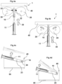
- Figure 3a further illustrates an initial/reset position of the holding means before the needle cap causes the holding means to rotate in the direction of the arrows.
- Figure 3c illustrates the holding means 20 being configured for applying equal forces 22 on the cap 10 perpendicular to the first direction 30 in opposite directions.
- the cap 10 prevents further rotation of the holding means 20 in the direction as indicated by the arrows.
- Continuously moving the syringe in the direction opposite the first direction 35 results in the holding means 20 applying a holding force in the first direction 30 exceeding a release force required to release the cap 10 from the syringe 11.
- the syringe is released from the cap 10 while the cap remains in the device.
- Figure 4a illustrates a cap 10 being held in the device 1 by the equal forces 22.
- the two holding means 20 may further comprise a torsion spring 25 and/or a tension spring 61 for strengthening the hold on the cap 10.
- a syringe 11 is inserted needle first into the cap 10 along the first direction 30.
- Figure 4b illustrates the holding means 20 being disengaged from the cap 10 when the cap 10 is displaced along the first direction 30 as the syringe 11 is inserted further into the cap 10 causing synchronized movement of the cap 10 and the syringe 11.
- the syringe 11 is recapped as the end of the cap 10 reaches the end stop 40 and a cap applying force is applied to the syringe 11 inserted in the cap 10.
- Figures 4c and 4d illustrate the removal of the recapped syringe by lifting substantially perpendicular or at an angle.
- Figure 5a illustrates a cross-sectional view of the holding means 20 comprising a shaft 23 with a rotational axis 24 perpendicular to the first axis 30.
- the holding means 20 are rotationally connected to the shaft 23 and configured for rotation around the rotational axis 24.
- Figure 5b illustrates a cross-sectional view of the distance adjusting means 60 comprising a tension spring 61 configured for adjusting the distance between two holding means 20.
- Each of the two holding means 20 illustrated in figure 5b are rotatable about the rotational axis 24 of a shaft 23.
- Each of the two shafts 23 are displaceable within a distance adjusting means 61 and the tension spring 61 connects the two shafts 23.
- the tension spring may be configured for moving the two holding means towards one another as indicated by the arrows.
- Figure 6a and 6b illustrate an embodiment of the holding means 20 comprising a torsion spring 25 configured for resetting the rotation of the holding means 20 relative to the shaft 23.
- Figure 7a describes a method of releasing 100 a needle cap 10 from a syringe 11 using the device 1.
- the method of releasing 100 comprises an act of inserting 200 a needle cap 10 connected to a syringe 11 between the at least two holding points 21 along the first direction 30. See figures 3a, 3b , 9a , and 12 .
- the method of releasing 100 comprises an act of pulling 300 the syringe 11 in a direction opposite from the first direction 35 causing the at least two holding points 21 to apply equal oppositely directed forces 22 to the cap 10.
- the act of releasing 100 may comprise pulling 300 the syringe 11 in a direction opposite from the first direction 35 while the at least two holding points 21 apply equal oppositely directed forces 22 to the cap 10.
- the method of releasing 100 comprises an act of releasing 400 the cap 10 from the syringe 11 by pulling 300 with a holding force exceeding the release force required to release the cap 10 from the syringe 11.
- the method of releasing 100 comprises an act of holding 500 the cap 10 between the at least two holding points 21.
- the act of holding 500 may comprise holding the cap 10 between the at least two holding points 21 in the passive position. This is best illustrated in figures 13b and 13c .
- the act of pulling 300 may further comprise an act of applying 350 an external force to the holding means 20 to achieve the engaged position causing the at least two holding points 21 to apply equal oppositely directed forces 22 to the cap 10. This is best seen in figure 13a .
- Figure 7b describes a method of recapping 600 a needle cap 10 from the device 1.
- the method of recapping 600 comprises an act of reinserting 700 the syringe 11 in a needle cap 10 arranged between at least two holding points 21 along the first direction 30 causing the at least two holding points 21 to disengage from the cap 10. This is illustrated in figure 4b .
- the method may comprise an act of reinserting 700 the syringe 11 in a needle cap 10 arranged between at least two holding points 21 along the first direction 30 as illustrated in figure 4a, 4b , 10 , and 13c .
- the method of recapping 600 comprises an act of pushing 800 the syringe 11 in the needle cap 10 against the end stop 40 by applying a cap applying force in the first direction 30 securing the cap 10 to the syringe 11. This is illustrated in figures 4b , 10b , and 13c .
- the method of recapping 600 may further comprise the act of lifting 900 the syringe 11 with the secured needle cap 10 up from the device 1.
- the method of recapping 600 may comprise the act of disengaging 950 from the cap 10 when the syringe 11 with the secured needle cap 10 is displaced along the direction opposite to the first direction 35, see figure 14 .
- Figures 8-10 illustrate an advantageous embodiment of the invention.
- Figures 8a illustrate the device 1 prepared for receiving a needle cap 10 between the compression pin comprising two holding points 21 and the compression face comprising a further holding point 21 (not visible).
- the device 1 may consist of two components:
- the compression pin may be removably inserted into the main body without the use of tools.
- the compression pin may be inserted into the main body from a bottom side and through and at least partially through the main body.
- Figure 8b illustrates a fastening aperture in the compression pin configured for receiving a pin in the main body for releasably securing the compression pin in the main body.
- the bottom of the device 1 may comprise fastening means 50 for releasably fastening the device to an external surface with an attachment force exceeding the applied release force and the cap applying force.
- the fastening means 50 may be a suction cup, a clamping device, a bench screw, an adhesive, a weighted part, used alone or in any combination.
- Figure 9a illustrates the device 1 holding a needle cap 10 of a syringe 11.
- the device comprises holding means 20 comprising three holding points 21 for holding the needle cap 10.
- the compression pin comprises two holding points 21 and the compression face comprises one holding point 21.
- the device 1 comprises an end stop 40 configured for withstanding a cap applying force in the first direction 30, as seen on figure 10b .
- the holding means 20 may comprise barbs configured for increasing the grip and hold of the needle cap 10 (not illustrated).
- the holding means 20 are configured for receiving the cap 10 when inserted along a first direction 30.
- Figure 9a further illustrates an initial/reset position of the compression pin before an inserted needle cap causes elastic deformation of the compression pin, as seen in figures 9b and 10 .
- Figure 9b illustrates the holding means 20 comprising the compression pin and compression face applying equal forces 22 on the cap 10 perpendicular to the first direction 30 in opposite directions.
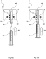
- Figure 10a illustrates a cap 10 being held in the device 1 by the equal forces 22.
- a syringe 11 is inserted needle first into the cap 10 along the first direction 30.
- Figure 10b illustrates the cap 10 sliding in the holding means 20 when the cap 10 is displaced along the first direction 30 as the syringe 11 is inserted further into the cap 10 causing synchronized movement of the cap 10 and the syringe 11.
- the syringe 11 is recapped as the end of the cap 10 reaches the end stop 40 and a cap applying force is applied to the syringe 11 inserted in the cap 10.
- the recapped syringe is removed from the device 1 by lifting substantially perpendicular, or at an angle, to the equal forces.
- Figures 11-14 illustrate another advantageous embodiment of the invention.
- Figures 11a and 11b respectively illustrate the device 1 prepared for receiving a needle cap 10 between the holding points 21 and a capped syringe 10,11 inserted into the device 1.
- Figure 12 illustrates inserting a needle cap 10 connected to a syringe 11 between the at least two holding points 21 along the first direction 30.
- Figures 13a, 13b, and 13c respectively illustrate uncapping the syringe 11, the holding means 20 holding the cap 10 in the device, and the syringe 11 being recapped against the end stop 40.
- Figure 14 illustrates the holding means 20 disengaging from the cap 10 when the cap is displaced along the direction opposite to the first direction 30.
- the holding means 20 comprises a force receiver configured for transferring an applied external force to a holding force in the first direction exceeding a release force required to release the cap 10 from the syringe 11.
- the holding means 20 are in the engaged position and the syringe 11 is moved in a direction opposite to the first direction 35, the syringe 11 is released from the cap 10 i, see figure 13a .
- the force receiver may apply equal forces 22, being a clamping force, to the cap 10 to ensure the cap 10 is held by the holding means 20 after the syringe 11 is released from the cap 10 by applying external force to the force receiver, and before the syringe 11 is reinserted into the needle cap 10.
- the clamping force may be smaller than the holding force and the cap 10 may disengage from holding means 20 in the passive position when the cap 10 or recapped syringe 10,11 is displaced along the direction opposite to the first direction 35. As illustrated, the clamping force can hold the cap 10 in the device 1 when arranged upside-down.
- the clamping force may further ensure that the holding means 20 are configured for automatically adapting to different sizes and shapes of needle caps 10.
- the force receiver is flexibly connected to the holding means 20 such that an applied external force causes the holding points 21 to engage the needle cap 10 with a holding force.
- the force receiver may be elastic deformable and decrease the distance between holding points 21 when the external force is applied. When the external force is no longer applied or the cap 10 is no longer held by the holding means 20, the force receiver may return to its original shape, pre-deformation.
- the elastic deformation is best seen in figures 12 , 13 , and 14 .
- the syringe 11 is recapped by inserting the syringe 11 into the cap 10 in the first direction 30 and applying a cap applying force against the end stop 40.
- the force receiver may be constructed by one or two slits in the holding means 20.
- the closed end of the slit(s) may provide a spring effect to allow plastic deformation of the force receiver relative to the holding means 20.
- the slits may be smaller than the needle cap to prevent the cap 10, capped or the recapped syringe 11 from exiting the holding means 20 in a direction that is not the opposite of the first direction 35.
- the external force may be applied by a healthcare worker pinching the force receiver and on the opposite side of the holding means 20 using two or more fingers, see figure 13a .
- the device 1 is a monolith, as best seen in figure 11a , and is constructed in a single material.
- the device comprises a shield 70 is arranged in front of holding means in the first direction 30 to further prevent needle stick injuries by creating a physical barrier between the hand of the healthcare worker and the syringe 11 being inserted into the cap 10 held in the device 1.
- the healthcare worker may hold the holding means 20 and/or force receiver or gripping means in one hand, all of which may be arranged behind the shield 70, and hold the syringe 11 to be uncapped, recapped, or removed in the other hand.
- the shield 70 may comprise means for fastening the device 1 the uniform or a keychain of a healthcare worker.
- the device 1 may be used both handheld by comprising gripping means and comprise fastening means 50 configured for enabling the device 1 to be used both as a handheld device and be mounted on a surface.
Landscapes
- Health & Medical Sciences (AREA)
- Vascular Medicine (AREA)
- Engineering & Computer Science (AREA)
- Anesthesiology (AREA)
- Biomedical Technology (AREA)
- Heart & Thoracic Surgery (AREA)
- Hematology (AREA)
- Life Sciences & Earth Sciences (AREA)
- Animal Behavior & Ethology (AREA)
- General Health & Medical Sciences (AREA)
- Public Health (AREA)
- Veterinary Medicine (AREA)
- Infusion, Injection, And Reservoir Apparatuses (AREA)
Applications Claiming Priority (2)
| Application Number | Priority Date | Filing Date | Title |
|---|---|---|---|
| DKPA202370178 | 2023-04-17 | ||
| DKPA202370495 | 2023-09-27 |
Publications (1)
| Publication Number | Publication Date |
|---|---|
| EP4450101A1 true EP4450101A1 (de) | 2024-10-23 |
Family
ID=90789378
Family Applications (1)
| Application Number | Title | Priority Date | Filing Date |
|---|---|---|---|
| EP24170750.4A Withdrawn EP4450101A1 (de) | 2023-04-17 | 2024-04-17 | Vorrichtung zum halten einer nadelkappe einer spritze und verfahren hierzu |
Country Status (3)
| Country | Link |
|---|---|
| US (1) | US20240342390A1 (de) |
| EP (1) | EP4450101A1 (de) |
| DK (1) | DK202430172A1 (de) |
Citations (5)
| Publication number | Priority date | Publication date | Assignee | Title |
|---|---|---|---|---|
| US5308582A (en) * | 1993-02-11 | 1994-05-03 | Serra Louis M | Syringe capping and uncapping device |
| FR3025433A1 (fr) * | 2014-09-09 | 2016-03-11 | Nemera La Verpilliere | Dispositif de retrait d'un capuchon de protection d'une aiguille de seringue |
| US20160331908A1 (en) * | 2014-02-04 | 2016-11-17 | Sanofi-Aventis Deutschland | Sheath removal mechanism |
| US20210213209A1 (en) * | 2018-05-29 | 2021-07-15 | Janssen Pharmaceuticals, Inc. | Cap for an injection device |
| US20220031959A1 (en) * | 2018-09-17 | 2022-02-03 | Becton, Dickinson And Company | Pen needle apparatus |
Family Cites Families (4)
| Publication number | Priority date | Publication date | Assignee | Title |
|---|---|---|---|---|
| US4915225A (en) * | 1988-05-09 | 1990-04-10 | Tabor Jr William D | Safety needle cap handler |
| US5087249A (en) * | 1990-08-21 | 1992-02-11 | Deal Richard E | Syringe cap holding device |
| DE102004022184A1 (de) * | 2004-05-05 | 2005-12-01 | Kaltenbach & Voigt Gmbh & Co. Kg | Vorrichtung zum Vermeiden von Nadelstichverletzungen |
| CN210096563U (zh) * | 2018-12-31 | 2020-02-21 | 马丽 | 一种医疗用针头复帽器 |
-
2024
- 2024-04-17 EP EP24170750.4A patent/EP4450101A1/de not_active Withdrawn
- 2024-04-17 DK DKPA202430172A patent/DK202430172A1/en unknown
- 2024-04-17 US US18/637,562 patent/US20240342390A1/en active Pending
Patent Citations (5)
| Publication number | Priority date | Publication date | Assignee | Title |
|---|---|---|---|---|
| US5308582A (en) * | 1993-02-11 | 1994-05-03 | Serra Louis M | Syringe capping and uncapping device |
| US20160331908A1 (en) * | 2014-02-04 | 2016-11-17 | Sanofi-Aventis Deutschland | Sheath removal mechanism |
| FR3025433A1 (fr) * | 2014-09-09 | 2016-03-11 | Nemera La Verpilliere | Dispositif de retrait d'un capuchon de protection d'une aiguille de seringue |
| US20210213209A1 (en) * | 2018-05-29 | 2021-07-15 | Janssen Pharmaceuticals, Inc. | Cap for an injection device |
| US20220031959A1 (en) * | 2018-09-17 | 2022-02-03 | Becton, Dickinson And Company | Pen needle apparatus |
Also Published As
| Publication number | Publication date |
|---|---|
| US20240342390A1 (en) | 2024-10-17 |
| DK202430172A1 (en) | 2024-11-14 |
Similar Documents
| Publication | Publication Date | Title |
|---|---|---|
| EP2403566B1 (de) | Kappensperre | |
| US5207653A (en) | Safety needle and cap combination device | |
| US6783003B2 (en) | Hypodermic needle holder | |
| US4904244A (en) | Apparatus for safely removing needles from hypodermic syringes | |
| US4906235A (en) | Needle guard | |
| US7083600B2 (en) | Safety needle and shield | |
| CN100531814C (zh) | 医用针的安全防护装置 | |
| KR102751238B1 (ko) | 의료용 주입기용 캡 | |
| EP0429052A1 (de) | Spritzenvorrichtung | |
| NO338675B1 (no) | Hette for medikamentavleveringsinnretning | |
| CN101626796A (zh) | 背针 | |
| US20120323216A1 (en) | Needleshield assembly | |
| US20190001075A1 (en) | Safety Syringe with Needle Redirection Device | |
| US7938800B2 (en) | Needleshield assembly and methods of use | |
| US9839489B2 (en) | Sharps end capture device and method | |
| US11925793B2 (en) | Apparatus for injecting a fluid, comprising a needle assembly and a needle retention device for retaining a needle of the needle assembly when attached to the apparatus, and needle retention device | |
| US8986258B2 (en) | Device for receiving a hypodermic syringe and hypodermic syringe for this device | |
| US20240342390A1 (en) | Device for holding a needle cap of a syringe, and method therefor | |
| EP2073874B1 (de) | Nadelsicherheitsvorrichtung | |
| US20060258991A1 (en) | Portable needle uncapping and recapping device | |
| US20150290401A1 (en) | Protective injection aid | |
| US20220249784A1 (en) | Syringe needle safety system | |
| MX2013008440A (es) | Dispositivo auxiliar para el manejo de jeringas tipo carpule durante el procedimiento de anestesia odontológica. | |
| US9480622B1 (en) | Medical device safety holder | |
| KR970006095B1 (ko) | 미리 충전된 약물병용의 예비 살균가능한 일회용 주사기 |
Legal Events
| Date | Code | Title | Description |
|---|---|---|---|
| PUAI | Public reference made under article 153(3) epc to a published international application that has entered the european phase |
Free format text: ORIGINAL CODE: 0009012 |
|
| STAA | Information on the status of an ep patent application or granted ep patent |
Free format text: STATUS: THE APPLICATION HAS BEEN PUBLISHED |
|
| AK | Designated contracting states |
Kind code of ref document: A1 Designated state(s): AL AT BE BG CH CY CZ DE DK EE ES FI FR GB GR HR HU IE IS IT LI LT LU LV MC ME MK MT NL NO PL PT RO RS SE SI SK SM TR |
|
| STAA | Information on the status of an ep patent application or granted ep patent |
Free format text: STATUS: THE APPLICATION IS DEEMED TO BE WITHDRAWN |
|
| 18D | Application deemed to be withdrawn |
Effective date: 20250424 |