EP4447871B1 - Prothesenschaft - Google Patents
Prothesenschaft Download PDFInfo
- Publication number
- EP4447871B1 EP4447871B1 EP22836072.3A EP22836072A EP4447871B1 EP 4447871 B1 EP4447871 B1 EP 4447871B1 EP 22836072 A EP22836072 A EP 22836072A EP 4447871 B1 EP4447871 B1 EP 4447871B1
- Authority
- EP
- European Patent Office
- Prior art keywords
- sensor
- prosthetic socket
- prosthetic
- electrical control
- amputation stump
- Prior art date
- Legal status (The legal status is an assumption and is not a legal conclusion. Google has not performed a legal analysis and makes no representation as to the accuracy of the status listed.)
- Active
Links
Images
Classifications
-
- A—HUMAN NECESSITIES
- A61—MEDICAL OR VETERINARY SCIENCE; HYGIENE
- A61F—FILTERS IMPLANTABLE INTO BLOOD VESSELS; PROSTHESES; DEVICES PROVIDING PATENCY TO, OR PREVENTING COLLAPSING OF, TUBULAR STRUCTURES OF THE BODY, e.g. STENTS; ORTHOPAEDIC, NURSING OR CONTRACEPTIVE DEVICES; FOMENTATION; TREATMENT OR PROTECTION OF EYES OR EARS; BANDAGES, DRESSINGS OR ABSORBENT PADS; FIRST-AID KITS
- A61F2/00—Filters implantable into blood vessels; Prostheses, i.e. artificial substitutes or replacements for parts of the body; Appliances for connecting them with the body; Devices providing patency to, or preventing collapsing of, tubular structures of the body, e.g. stents
- A61F2/50—Prostheses not implantable in the body
- A61F2/76—Means for assembling, fitting or testing prostheses, e.g. for measuring or balancing, e.g. alignment means
-
- A—HUMAN NECESSITIES
- A61—MEDICAL OR VETERINARY SCIENCE; HYGIENE
- A61F—FILTERS IMPLANTABLE INTO BLOOD VESSELS; PROSTHESES; DEVICES PROVIDING PATENCY TO, OR PREVENTING COLLAPSING OF, TUBULAR STRUCTURES OF THE BODY, e.g. STENTS; ORTHOPAEDIC, NURSING OR CONTRACEPTIVE DEVICES; FOMENTATION; TREATMENT OR PROTECTION OF EYES OR EARS; BANDAGES, DRESSINGS OR ABSORBENT PADS; FIRST-AID KITS
- A61F2/00—Filters implantable into blood vessels; Prostheses, i.e. artificial substitutes or replacements for parts of the body; Appliances for connecting them with the body; Devices providing patency to, or preventing collapsing of, tubular structures of the body, e.g. stents
- A61F2/50—Prostheses not implantable in the body
- A61F2002/5016—Prostheses not implantable in the body adjustable
- A61F2002/502—Prostheses not implantable in the body adjustable for adjusting length
-
- A—HUMAN NECESSITIES
- A61—MEDICAL OR VETERINARY SCIENCE; HYGIENE
- A61F—FILTERS IMPLANTABLE INTO BLOOD VESSELS; PROSTHESES; DEVICES PROVIDING PATENCY TO, OR PREVENTING COLLAPSING OF, TUBULAR STRUCTURES OF THE BODY, e.g. STENTS; ORTHOPAEDIC, NURSING OR CONTRACEPTIVE DEVICES; FOMENTATION; TREATMENT OR PROTECTION OF EYES OR EARS; BANDAGES, DRESSINGS OR ABSORBENT PADS; FIRST-AID KITS
- A61F2/00—Filters implantable into blood vessels; Prostheses, i.e. artificial substitutes or replacements for parts of the body; Appliances for connecting them with the body; Devices providing patency to, or preventing collapsing of, tubular structures of the body, e.g. stents
- A61F2/50—Prostheses not implantable in the body
- A61F2002/5016—Prostheses not implantable in the body adjustable
- A61F2002/5026—Prostheses not implantable in the body adjustable for adjusting a diameter
-
- A—HUMAN NECESSITIES
- A61—MEDICAL OR VETERINARY SCIENCE; HYGIENE
- A61F—FILTERS IMPLANTABLE INTO BLOOD VESSELS; PROSTHESES; DEVICES PROVIDING PATENCY TO, OR PREVENTING COLLAPSING OF, TUBULAR STRUCTURES OF THE BODY, e.g. STENTS; ORTHOPAEDIC, NURSING OR CONTRACEPTIVE DEVICES; FOMENTATION; TREATMENT OR PROTECTION OF EYES OR EARS; BANDAGES, DRESSINGS OR ABSORBENT PADS; FIRST-AID KITS
- A61F2/00—Filters implantable into blood vessels; Prostheses, i.e. artificial substitutes or replacements for parts of the body; Appliances for connecting them with the body; Devices providing patency to, or preventing collapsing of, tubular structures of the body, e.g. stents
- A61F2/50—Prostheses not implantable in the body
- A61F2002/5016—Prostheses not implantable in the body adjustable
- A61F2002/5027—Prostheses not implantable in the body adjustable for adjusting cross-section
Definitions
- the invention relates to a prosthetic shaft having an open proximal end, a distal end with a distal contact surface and a lateral surface extending between the proximal end and the distal end, wherein the effective length of the prosthetic shaft extends from the distal contact surface of the distal end to the proximal end, wherein an effective circumference of the prosthetic shaft runs along the inner surface of the lateral surface.
- Such a prosthetic stem is, for example, from the DE 10 2010 019 843 A1 known.
- the prosthetic socket which is used as part of a prosthesis, has an open proximal end into which an amputation stump is inserted when the prosthesis, of which the prosthesis socket is a part, is to be worn by the wearer of the prosthesis.
- a prosthetic device such as a knee joint, a lower leg tube, a prosthetic foot, or another type of prosthesis, is arranged at the closed distal end of the prosthetic socket.
- Prosthetic sockets are used for both lower extremity and upper extremity prostheses.
- the amputation stump is usually covered by a liner made of an elastic material, such as silicone.
- the amputation stump rests against the distal contact surface of the prosthetic socket, with a liner possibly located between the amputation stump and the distal contact surface.
- the distal contact surface is formed by a separate element or component.
- the distal end is preferably closed.
- the distal contact surface is designed as a kind of double bottom parallel to the located at the distal end of the shaft.
- the distal end of the prosthetic shaft can also be open.
- the prosthesis bears the wearer's entire weight with every step the wearer takes and is therefore exposed to high mechanical stress.
- the problem is that the shape of the amputation stump is subject to change, particularly in the initial period after the amputation, as muscles in the amputation stump in particular atrophy due to inactivation and scars and tissue hardening develop. Over the course of a day, the stump volume also changes due to fluid redistribution in the tissue.
- the disadvantage is that despite this adjustability of the effective length and circumference, the fit of the prosthetic socket can be adjusted in a suboptimal manner by the wearer of the respective prosthesis, thus causing pain and problems. Therefore, it is very important for the user and wearer of a It is often not possible, or at least not easy, to determine whether a decrease in the volume of the amputation stump should be accommodated by reducing the effective circumference, reducing the effective length, or both. The same applies to an increase in the volume of the amputation stump, as occurs over the course of a day. If the wearer of the prosthesis increases the effective circumference of the prosthetic socket, this can counteract the high pressure on the amputation stump caused by the increase in volume and provide relief.
- US 2019/183 663 A1 discloses a prosthetic socket with an actuator, via which the inner circumference of the prosthetic socket can be changed, and a sensor which is coupled to a control device which is connected to the actuator and activates or deactivates it depending on the received sensor signals.
- US 2019/183 663 A1 shows the features of the preamble of claim 1.
- the invention is therefore based on the object of eliminating or at least alleviating the disadvantages of the prior art.
- the invention solves the stated problem by a prosthetic socket according to the preamble of claim 1, which is characterized in that the prosthetic socket has an electrical control and an adjustment device for the effective length and the effective circumference and at least one first sensor for detecting a force acting distally on the amputation stump and at least one second sensor for detecting radial forces acting on the amputation stump, the measured values of which are transmitted to the electrical control, wherein the electrical control is designed to control the adjustment device depending on the measured values of both sensors.
- the prosthetic socket according to the invention has an adjustment device with which the effective length and effective circumference of the prosthetic socket can be adjusted and changed.
- the adjustment device is controlled via the electrical control of the prosthetic socket, which can be, for example, an electronic data processing device.
- the effective circumference and effective length can preferably be adjusted to the individual needs of the prosthetic wearer and the current situation of the amputation stump.
- the prosthetic socket has a first sensor for detecting a force acting distally on the amputation stump and at least one second sensor for detecting forces acting radially on the amputation stump.
- the first sensor and/or the second sensor have a pressure sensor, a force sensor, a moment sensor and/or a deformation sensor.
- a pressure sensor can detect a pressure if conclusions about the prevailing pressure can be drawn from the measured values of the pressure sensor. It is not necessary for the pressure sensor to measure the pressure directly.
- a force sensor is understood to be any sensor from whose measured data conclusions about a force can be drawn.
- a moment sensor is any sensor whose measured values allow conclusions about a moment
- a deformation sensor is any sensor from whose measured values statements about a deformation of the amputation stump can be made.
- hydraulic or pneumatic systems can be used as the first sensor and/or second sensor.
- a hydraulic or pneumatic system for example, the pressure of the hydraulic fluid or gas contained in the hydraulic or pneumatic system is measured. It is a measure of the pressure that is applied externally, for example, by the The amputation stump and/or the prosthetic socket are applied to the system.
- the working medium of a pneumatic system is preferably a compressible gas; the working medium of a hydraulic system is preferably an incompressible fluid, for example a liquid, preferably a hydraulic oil.
- an optical sensor can be used as the first and/or second sensor, which measures the applied pressure using optical measurement.
- a pressure-sensitive element such as a spring element, which is expanded or compressed to a greater or lesser extent by the amputation stump, or is deformed or deflected in some other way. This expansion, compression, deformation, or deflection can then be detected by the optical sensor.
- a deformation sensor can, for example, be a capacitive and/or resistive sensor.
- a capacitive sensor the outer surface of the amputation stump or a liner placed over it, on the one hand, and the inner surface of the prosthetic socket, on the other, form the two plates of an electrical capacitor. The distance between the two plates thus formed determines the capacitance of the capacitor, which is measured. A change in distance and thus a deformation of the amputation stump changes the capacitance of the capacitor. The distance can thus be determined indirectly via the capacitance of the capacitor.
- a change in the resistance therefore contains information about a deformation of the amputation stump.
- a strain gauge or a Hall probe can be used as the first sensor and/or as the second sensor to detect deformation of the amputation stump.
- a strain gauge can be used as the first sensor and/or the second sensor to detect the deformation of a part of the prosthetic socket's adjustment mechanism.
- a strain gauge can be used in combination with a load cell to detect the force exerted on the residual limb.
- a first sensor and a second sensor are used, the measured values of which are used to control the adjustment device.
- the first sensor and the second sensor send their measured values in the form of measurement signals to the electrical control unit.
- the electrical control unit is configured to determine, based on these measured values, whether and, if so, how the effective length and circumference of the prosthetic socket need to be adjusted. Furthermore, the electrical control unit is configured to generate control signals and transmit them to the adjustment device. The adjustment device is controlled by the control signals in such a way that the effective length and circumference are adjusted accordingly.
- the electrical control unit detects, based on the measured values transmitted to it, that only one of the two, for example the effective circumference or the effective length, needs to be changed. Regardless of whether the effective length or the effective circumference or both variables need to be changed, the detected distal pressure and the detected radial pressure are input variables on the basis of which the electrical control unit carries out its algorithms and processes and generates the control signals. With a prosthetic socket according to the invention, it is not possible for the electrical control unit to control the adjustment device without both the distal pressure and the radial pressure being detected and transmitted to the electrical control unit.
- the adjustment device has a movable end element by which the effective length of the prosthetic shaft can be varied, and/or at least one movable circumferential element by which the effective circumference can be varied.
- the movable end element then preferably forms the distal contact surface.
- the at least one movable peripheral element is arranged such that it surrounds at least part of the inner surface of the lateral surface of the Prosthetic shaft.
- the at least one movable circumferential element is arranged in a recess in the main body of the prosthetic shaft.
- the effective circumference of the prosthetic shaft can be reduced in a particularly simple manner by moving the at least one movable circumferential element radially inward in the recess in the main body of the prosthetic shaft, i.e. in the direction of the longitudinal axis of the prosthetic shaft, along which the effective length of the prosthetic shaft also extends.
- the at least one movable circumferential element in this embodiment is moved in the opposite direction, i.e. radially outward with respect to the longitudinal axis of the prosthetic shaft.
- the movable circumferential elements can be moved so that they overlap one another to a lesser extent, thereby increasing the effective circumference of the prosthetic socket.
- a combination of the different designs for example several overlapping circumferential elements and at least one circumferential element positioned in a recess of the base body, is also possible.
- the prosthetic socket preferably has at least one drive that moves the movable end element.
- the prosthetic socket has at least one drive that moves the at least one movable peripheral element.
- the movements are performed by the same drive, so that the prosthetic socket has only a single drive.
- the drive(s) are part of the adjustment device.
- the first sensor detects a force exerted on the movable end element by an amputation stump inserted into the prosthetic socket.
- the second sensor detects a force exerted on the movable peripheral element by an amputation stump inserted into the prosthetic socket.
- the electrical control preferably an electronic data processing device, is configured to move the adjustment device, for example the movable end element and/or the at least one movable peripheral element, depending on the measured values of the sensors.
- the values detected by the sensors are compared in the electrical control with a respective target value or a target value range.
- the target values stored in the electrical control system can include both absolute values and desired ratios of the detected forces on the amputation stump.
- the goal is generally to achieve the most even pressure distribution possible from the prosthetic socket to the amputation stump. However, this is subject to user-specific individual fluctuations and is preferably determined and tested for each patient.
- the electrical control moves the movable element away from the amputation stump in order to reduce the pressure load. If a detected force on one of the movable elements is, for example, smaller than a predetermined target value, the electrical control moves the movable element in such a way that the pressure is increased.
- the respective movable element Element is moved, for example, toward the amputation stump.
- both the movable end element and the at least one movable peripheral element are moved simultaneously. However, it may be sufficient to move only the end element or only the peripheral element to achieve the desired pressure distribution.
- the electrical control sends control signals to the drive, for example, an electric motor, which moves the respective element, i.e., the end element and/or the peripheral element.
- the electrical control moves the movable end element and/or the at least one movable peripheral element such that the volume within the prosthetic socket decreases. If, however, the pressure detected at both pressure sensors is higher than the predetermined target value for the respective sensor, the electrical control moves the movable end element and/or the at least one movable peripheral element such that the volume within the prosthetic socket increases.
- the range between the first target value and the predetermined second target value can be referred to and viewed as the target value range.
- Coupling of the two movements of the movable end element and the movable peripheral element is preferably achieved by using a mechatronic control system, which includes the electrical control and the at least one drive.
- the prosthetic socket has at least one additional sensor, preferably a humidity sensor, a temperature sensor and/or an oxygen saturation sensor, and the electrical control is configured to move the movable end element and/or the movable peripheral element depending on the measured values of the first and second sensors as well as this at least one additional sensor.
- the humidity sensor is arranged such that it detects the humidity between the prosthetic socket and the amputation stump, preferably between the Prosthetic socket and a liner containing the amputation stump.
- the additional sensor is a temperature sensor, it is preferably arranged so that the temperature is measured within the prosthetic socket, i.e., preferably in the space between the prosthetic socket and the amputation stump.
- An oxygen saturation sensor is preferably arranged so that it can determine the oxygen saturation of the blood within the amputation stump.
- the at least one additional sensor is configured to record sensor data from which conclusions can be drawn about the movement state of the wearer of the prosthetic socket.
- the at least one additional sensor comprises at least one inertial sensor, which is preferably configured to determine a spatial position, a speed and/or an angular change of the prosthetic socket or of a component directly or indirectly connected to the prosthetic socket.
- the electrical control can control the adjustment device such that the effective length and/or the effective circumference of the prosthetic socket increase when the wearer of the prosthetic socket is sitting. In this case, no, or at least no regularly recurring, movements of the prosthetic socket are detected. Also, the prosthetic socket is not subjected to as much or even not at all.
- FIG. 1 schematically shows various components of a prosthetic socket according to a first embodiment of the present invention.
- the prosthetic socket has a base body 2, which has an open proximal end 4 and a distal end 6, which is closed in the embodiment shown. It has also has a recess 8 in which a peripheral element 10 is arranged, which is movable relative to the base body 2.
- a movable end element 12 At the distal end 6 of the base body 2 there is a movable end element 12, which in Figure 1 shown next to the base body 2.
- the movable peripheral element 10 is movable along the radial double arrow 14, and the movable end element 12 is movable along the axial double arrow 16.
- the terms “axial” and “radial” refer to the longitudinal extent of the prosthetic shaft, which extends along the effective length of the prosthetic shaft from the inner surface of the distal end 6 to the proximal end 4.
- a distal sensor 18 is arranged at the distal end 6 of the base body 2. This sensor measures an axial pressure or an axial force. This is referred to as the distal force and is the resulting total force on a shaft adapter, which is Figure 1 not shown for reasons of clarity. Additional prosthetic elements can be arranged on the socket adapter, for example a prosthetic knee joint in the exemplary embodiment shown, a transfemoral prosthesis.
- a first sensor 20 is positioned on the movable end element 12 and measures the pressure or a force by which the distal end of an amputation stump is loaded. This pressure is referred to as axial pressure.
- the prosthetic socket has a second sensor 22, which in the exemplary embodiment shown is arranged on the movable peripheral element and measures a radial force or a radial pressure.
- a ramus pressure sensor 24 measures the force of a bony attachment of the prosthetic socket and is also referred to as a ramus sensor.
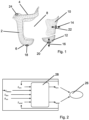
- Figure 2 shows schematically how the individual data or measured values recorded by the individual sensors can be used.
- the aim is to achieve the best possible selection of the effective length x axial and the effective circumference x circ , which can be changed and adjusted by moving the movable end element 12 and the movable circumferential element 10. These form the target configuration 26.
- the measured values S circ of the second pressure sensor 22, S ramus of the ramus pressure sensor 24, S dist of the distal pressure sensor 18 and S axial of the first pressure sensor 20 are fed to an electrical control system 28.
- additional data D ext are also received, for example from external sensors located in Figure 1 are not shown, and/or, for example, manual user specifications are taken into account and also passed on to the electrical control 28.
- the electrical control unit 28 calculates values for the effective circumference x circ and the effective length x axial of the prosthetic shaft from the data and measured values provided to it and controls a drive for the respective adjustment device in such a way that these values are adjusted. As a result, the measured values of the various sensors and thus the input values provided to the electrical control unit 28 change until the target configuration 26, which contains, for example, target values for the individual measured variables, is reached.
Landscapes
- Health & Medical Sciences (AREA)
- Cardiology (AREA)
- Oral & Maxillofacial Surgery (AREA)
- Transplantation (AREA)
- Engineering & Computer Science (AREA)
- Biomedical Technology (AREA)
- Heart & Thoracic Surgery (AREA)
- Vascular Medicine (AREA)
- Life Sciences & Earth Sciences (AREA)
- Animal Behavior & Ethology (AREA)
- General Health & Medical Sciences (AREA)
- Public Health (AREA)
- Veterinary Medicine (AREA)
- Prostheses (AREA)
Description
- Die Erfindung betrifft einen Prothesenschaft, der ein offenes proximales Ende, ein distales Ende mit einer distalen Anlagefläche und eine Mantelfläche aufweist, die sich zwischen dem proximalen Ende und dem distalen Ende erstreckt, wobei sich die wirksame Länge des Prothesenschaftes von der distalen Anlagefläche des distalen Endes bis zum proximalen Ende erstreckt, wobei ein wirksamer Umfang des Prothesenschaftes entlang der Innenfläche der Mantelfläche verläuft.
- Ein derartiger Prothesenschaft ist beispielsweise aus der
DE 10 2010 019 843 A1 bekannt. Der Prothesenschaft, der als Teil einer Prothese verwendet wird, verfügt über ein offenes proximales Ende, in das ein Amputationsstumpf eingeführt wird, wenn die Prothese, deren Teil der Prothesenschaft ist, vom Träger der Prothese getragen werden soll. Am geschlossenen distalen Ende des Prothesenschaftes ist eine Protheseneinrichtung, beispielsweise ein Kniegelenk, ein Unterschenkelrohr oder ein Prothesenfuß oder eine andere Art von Prothese angeordnet. Prothesenschäfte werden sowohl für Prothesen der unteren Extremität als auch für Prothesen der oberen Extremität verwendet. Um eine besonders gute Haftung des Prothesenschaftes am Amputationsstumpf und gegebenenfalls eine Polsterung zu erreichen, ist der Amputationsstumpf in der Regel von einem Liner umhüllt, der aus einem elastischen Material, beispielsweise Silikon, hergestellt wird. - Der Amputationsstumpf liegt an der distalen Anlagefläche des Prothesenschaftes an, wobei sich ein Liner zwischen dem Amputationsstumpf und der distalen Anlagefläche befinden kann. Die distale Anlagefläche wird durch ein separates Element oder Bauteil gebildet. Das distale Ende ist vorzugsweise geschlossen ausgebildet. In diesem Fall ist die distale Anlagefläche als eine Art doppelter Boden parallel zum distalen Ende des Schaftes angeordnet. Das distale Ende des Prothesenschaftes kann auch offen ausgestaltet sein.
- Insbesondere bei Prothesen der unteren Extremität, beispielsweise Oberschenkelprothesen oder Unterschenkelprothesen trägt die Prothese bei jedem Schritt, den der Träger der Prothese geht oder läuft, das Gesamtgewicht des Trägers und ist daher hohen mechanischen Belastungen ausgesetzt. Gleiches gilt für den sich im Prothesenschaft befindenden Amputationsstumpf. Es ist daher sehr wichtig, dass der Prothesenschaft besonders gut an die geometrische Form des Amputationsstumpfes angepasst ist, um Druckstellen und damit Wunden und Schmerzen zu vermeiden. Problematisch ist dabei, dass insbesondere in der ersten Zeit nach der Amputation die Form des Amputationsstumpfes Veränderungen unterworfen ist, da sich insbesondere im Amputationsstumpf befindenden Muskeln aufgrund der Inaktivierung zurück bilden und sich Narben und Gewebeverhärtungen ausbilden. Im Laufe eines Tages verändert sich zudem das Stumpfvolumen durch Flüssigkeitsumlagerungen im Gewebe.
- Um diesen Änderungen im Volumen des Amputationsstumpfes und in dessen Form Rechnung zu tragen, ist es aus dem Stand der Technik bekannt, sowohl den wirksamen Umfang des Prothesenschaftes als auch die wirksame Länge des Prothesenschaftes veränderbar auszugestalten. Die
DE 10 2010 019 843 A1 verfügt dafür über eine Spanneinrichtung, die beispielsweise über ein Zugseil oder einen Draht verfügt, über den eine Spannung auf die verschiedenen Elemente des Prothesenschaftes ausgeübt werden kann. Dadurch lässt sich der wirksame Umfang des Prothesenschaftes auch für den Benutzer des Prothesenschaftes selbst einstellen. Zusätzlich verfügt der dort beschriebene Schaft über eine Einstelleinrichtung, über die die wirksame Länge des Prothesenschaftes, der im Stand der Technik auch als Hülse bezeichnet wird, eingestellt werden kann. - Nachteilig ist, dass trotz dieser Einstellbarkeit der wirksamen Länge und des wirksamen Umfanges die Passform des Prothesenschaftes durch den Träger der jeweiligen Prothese in nicht optimaler Weise angepasst und so Schmerzen und Probleme hervorgerufen werden können. So ist es für den Benutzer und Träger einer Prothese oft nicht oder zumindest nicht leicht zu erkennen, ob einer Abnahme des Volumens des Amputationsstumpfes durch die Verringerung des wirksamen Umfangs, die Verringerung der wirksamen Länge oder beider Maßnahmen Rechnung getragen werden soll. Gleiches gilt für eine Vergrößerung des Volumens des Amputationsstumpfes, wie sie im Laufe eines Tages vorkommt. Vergrößert der Träger der Prothese den wirksamen Umfang des Prothesenschaftes, kann dies dem durch die Volumenzunahme entstandenen hohen Druckes, der auf den Amputationsstumpf wirkt, entgegenwirken und Linderung bringen. Gleichzeitig kann dies jedoch zur Folge haben, dass die Gewichts- und Kräfteverteilung innerhalb des Prothesenschaftes nicht mehr optimal ist, sodass es zu Druckstellen und Schmerzen kommen kann. Umgekehrt kann die zu starke Vergrößerung der wirksamen Länge des Prothesenschaftes dazu führen, dass das distale Ende des Amputationsstumpfes den Kontakt mit der Innenfläche des distalen Endes des Prothesenschaftes verliert. Auch dabei kann die Kräfteverteilung innerhalb des Systems aus Prothesenschaft und Amputationsstumpf so verändert werden, dass es zu Druckstellen und Schmerzen kommt. Es besteht insbesondere die Gefahr von Ödembildungen am distalen Ende des Amputationsstumpfes.
- Die
US 2019/183 663 A1 offenbart einen Prothesenschaft mit einem Aktuator, über den der Innenumfang des Prothesenschaftes veränderbar ist, und einem Sensor, der mit einer Steuerungseinrichtung gekoppelt ist, die mit dem Aktuator verbunden ist und diesen in Abhängigkeit von den empfangenen Sensorsignalen aktiviert oder deaktiviert.US 2019/183 663 A1 zeigt die Merkmale des Oberbegrifs des Anspruchs 1. - Der Erfindung liegt daher die Aufgabe zugrunde, die Nachteile aus dem Stand der Technik zu beheben oder zumindest zu lindern.
- Die Erfindung löst die gestellte Aufgabe durch einen Prothesenschaft gemäß dem Oberbegriff des Anspruchs 1, der sich dadurch auszeichnet, dass der Prothesenschaft eine elektrische Steuerung und eine Einstelleinrichtung für die wirksame Länge und den wirksamen Umfang aufweist und wenigstens einen ersten Sensor zum Erfassen einer distal auf den Amputationsstumpf wirkenden Kraft und wenigstens einen zweiten Sensor zum Erfassen von radial auf den Amputationsstumpf wirkenden Kräften aufweist, deren Messwerte an die elektrische Steuerung übermittelt werden, wobei die elektrische Steuerung eingerichtet ist, in Abhängigkeit der Messwerte beider Sensoren die Einstelleinrichtung zu steuern.
- Der erfindungsgemäße Prothesenschaft verfügt über eine Einstelleinrichtung, mit der die wirksame Länge und der wirksame Umfang des Prothesenschaftes eingestellt und verändert werden kann. Die Einstelleinrichtung wird über die elektrische Steuerung des Prothesenschaftes, die beispielsweise eine elektronische Datenverarbeitungseinrichtung sein kann, gesteuert. So können vorzugsweise der wirksame Umfang und die wirksame Länge jeweils auf die individuellen Bedürfnisse des Trägers der Prothese und die aktuelle Situation des Amputationsstumpfes eingestellt werden.
- Der Prothesenschaft verfügt über einen ersten Sensor zum Erfassen einer distal auf den Amputationsstumpf wirkenden Kraft und wenigstens einen zweiten Sensor zum Erfassen von radial auf den Amputationsstumpf wirkenden Kräften Vorzugsweise weisen der erste Sensor und/oder der zweite Sensor einen Drucksensor, einen Kraftsensor, einen Momentensensor und/oder einen Verformungssensor auf. Im Sinne der vorliegenden Anmeldung kann ein Drucksensor einen Druck erfassen, wenn sich aus den Messwerten des Drucksensors Rückschlüsse auf den herrschenden Druck ziehen lassen. Es ist nicht notwendig, dass der Drucksensor direkt den Druck misst. Entsprechend wird unter einem Kraftsensor jeder Sensor verstanden, aus dessen Messdaten Rückschlüsse auf eine Kraft gezogen werden können. Ein Momentensensor ist im Rahmen der vorliegenden Erfindung jeder Sensor, dessen Messwerte Rückschlüsse auf ein Moment erlauben, und ein Verformungssensor ist jeder Sensor, aus dessen Messwerten Aussagen über eine Verformung des Amputationsstumpfes getroffen werden können.
- Als erster Sensor und/oder zweiter Sensor können beispielsweise hydraulisch oder pneumatisch arbeitende Systeme verwendet werden. Bei einem hydraulischen oder einem pneumatischen System wird beispielsweise der Druck des Hydraulikfluids oder des Gases, das sich in dem hydraulischen oder pneumatischen System befindet, gemessen. Er ist ein Maß für den Druck, der von außen, beispielsweise durch den Amputationsstumpf und/oder den Prothesenschaft auf das System aufgebracht wird. Das Arbeitsmedium eines pneumatischen Systems ist vorzugsweise ein kompressibles Gas, das Arbeitsmedium eines hydraulischen Systems ist vorzugsweise ein inkompressibles Fluid, beispielsweise eine Flüssigkeit, vorzugsweise ein Hydrauliköl.
- Als erster und/oder zweiter Sensor kann beispielsweise ein optischer Sensor verwendet werden, der mittels optischer Messung den wirkenden Druck misst. Dazu kann beispielsweise ein drucksensibles Element, beispielsweise ein Federelement verwendet werden, das durch den Amputationsstumpf mehr oder weniger stark ausdehnt oder komprimiert wird oder auf andere Weise verformt oder ausgelenkt wird. Diese Ausdehnung, Kompression, Verformung oder Auslenkung kann dann durch den optischen Sensor detektiert werden.
- Ein Verformungssensor kann beispielsweise ein kapazitiv und/oder resistiv wirkender Sensor sein. Bei einem kapazitiven Sensor bilden beispielsweise die Außenseite des Amputationsstumpfes oder eines darüber gezogenen Liners einerseits und die Innenfläche des Prothesenschaftes andererseits die beiden Platten eines elektrischen Kondensators. Der Abstand der beiden so gebildeten Platten bestimmt die Kapazität des Kondensators, die gemessen wird. Eine Abstandsänderung und damit eine Verformung des Amputationsstumpfes verändert die Kapazität des Kondensators. So kann der Abstand indirekt über die Kapazität des Kondensators bestimmt werden.
- Bei einem resistiven Sensor verändert eine Verformung des Amputationsstumpfes einen elektrischen Widerstand, der gemessen wird. Eine Änderung des Widerstandes enthält folglich Informationen über eine Verformung des Amputationsstumpfes.
- Alternativ oder zusätzlich dazu kann als erster Sensor und/oder als zweiter Sensor ein Dehnungsmessstreifen oder eine Hall-Sonde verwendet werden, um eine Verformung des Amputationsstumpfes zu erfassen.
- Alternativ oder zusätzlich dazu kann als erster Sensor und/oder als zweiter Sensor ein Dehnungsmessstreifen verwendet werden, um die Verformung eines Teiles der Einstelleinrichtung des Prothesenschaftes zu erfassen. Weiterhin kann ein Dehnungsmessstreifen in Kombination mit einer Wägezelle genutzt werden um eine auf den Stumpf ausgeübte Kraft zu erfassen.
- Wichtig ist unabhängig von der Wahl der Sensoren, dass ein erster Sensor und ein zweiter Sensor verwendet werden, deren Messwerte zur Steuerung der Einstelleinrichtung verwendet werden.
- Der erste Sensor und der zweite Sensor senden ihre Messwerte in Form von Messsignalen an die elektrische Steuerung. Diese ist eingerichtet, in Abhängigkeit dieser Messwerte zu ermitteln, ob und wenn ja wie die wirksame Länge und der wirksame Umfang des Prothesenschaftes angepasst werden muss. Zudem ist die elektrische Steuerung eingerichtet, Steuersignale zu erzeugen und an die Einstelleinrichtung zu übermitteln. Die Einstelleinrichtung wird durch die Steuersignale derart angesteuert, dass die wirksame Länge und der wirksame Umfang entsprechend angepasst werden.
- Bei einem erfindungsgemäßen Prothesenschaft ist es nicht zwangsläufig nötig, dass die wirksame Länge und der wirksame Umfang immer gleichzeitig verändert werden. Es ist durchaus möglich, dass für bestimmte Situation die elektrische Steuerung anhand der ihr übermittelten Messwerte erkennt, dass nur einer der beiden, beispielsweise der wirksame Umfang oder die wirksame Länge, zu verändern sind. Unabhängig davon, ob die wirksame Länge oder der wirksame Umfang oder beide Größen zu verändern sind, sind jeweils der erfasste distale Druck unter erfasste radiale Druck Eingangsgrößen, auf deren Grundlage die elektrische Steuerung ihre Algorithmen und Verfahren durchführt und die Steuersignale generiert. Es ist bei einem erfindungsgemäßen Prothesenschaft nicht möglich, dass die elektrische Steuerung die Einstelleinrichtung steuert, ohne dass sowohl der distale Druck als auch der radiale Druck erfasst und an die elektrische Steuerung übermittelt wurden.
- Vorzugsweise verfügt die Einstelleinrichtung über ein bewegbares Endelement, durch das die wirksame Länge des Prothesenschaftes veränderbar ist, und/oder über wenigstens ein bewegbares Umfangselement, durch das der wirksame Umfang veränderbar ist. Das bewegbare Endelement bildet dann vorzugsweise die distale Anlagefläche.
- In einer bevorzugten Ausgestaltung wird durch die Veränderung der wirksamen Länge und des wirksamen Umfanges eine Veränderung des distalen Druckes und des radialen Druckes erreicht, was zu einer Veränderung der Messwerte der beiden Sensoren führt. Auf diese Weise lässt sich eine Regelschleife erzeugen. Vorzugsweise greift die elektrische Steuerung auf einen elektronischen Datenspeicher zu, in dem Sollwerte für die Messwerte der beiden Sensoren, vorzugsweise für den distalen Druck und den radialen Druck hinterlegt sind. Die elektrische Steuerung ist eingerichtet, diesen hinterlegten Sollwert, beispielsweise einen hinterlegten distalen Druck und radialen Druck und die Messwerte der Sensoren so zu verarbeiten, dass sie miteinander vergleichbar sind, sodass die elektrische Steuerung aus diesem Vergleich ermittelt, ob und in welche Richtung der wirksame Umfang und die wirksame Länge verändert werden müssen.
- Vorzugsweise bildet das bewegbare Endelement die distale Anlagefläche des distalen Endes des Prothesenschaftes. Um also die wirksame Länge des Prothesenschaftes zu verändern, wird in diesem Fall das bewegbare Endelement in Richtung auf das offene proximale Ende des Prothesenschaftes oder von ihm weg bewegt. Um die wirksame Länge des Prothesenschaftes zu reduzieren, wird das bewegbare Endelement in Richtung auf das proximale Ende des Prothesenschaftes bewegt. Eine Bewegung in die umgekehrte Richtung, also vom proximalen Ende des Prothesenschaftes weg, führt zu einer Vergrößerung der wirksamen Länge des Prothesenschaftes.
- Vorzugsweise ist das wenigstens eine bewegbare Umfangselement so angeordnet, dass es wenigstens einen Teil der Innenfläche der Mantelfläche des Prothesenschaftes bildet. Besonders bevorzugt ist das wenigstens eine bewegbare Umfangselement in einer Ausnehmung des Grundkörpers des Prothesenschaftes angeordnet. In diesem Fall lässt sich der wirksame Umfang des Prothesenschaftes auf besonders einfache Weise dadurch verringern, dass das wenigstens eine bewegbare Umfangselement in der Ausnehmung des Grundkörpers des Prothesenschaftes nach radial innen, also in Richtung auf die Längsachse des Prothesenschaftes, entlang derer sich auch die wirksame Länge des Prothesenschaftes erstreckt, bewegt wird. Um den wirksamen Umfang des Prothesenschaftes zu vergrößern, wird das wenigstens eine bewegbare Umfangselement in dieser Ausgestaltung in die entgegengesetzte Richtung, also nach radial außen in Bezug auf die Längsachse des Prothesenschaftes, bewegt.
- Alternativ oder zusätzlich dazu verfügt der Prothesenschaft über mehrere Umfangselemente, die überlappend angeordnet sind und die gemeinsam zumindest einen Teil des wirksamen Umfangs, bevorzugt jedoch den gesamten wirksamen Umfang des Prothesenschaftes bilden. Diese Ausgestaltung wird oft als "Tulpe" bezeichnet. Der Prothesenschaft verfügt in diesem Fall vorzugsweise über eine Spanneinrichtung, beispielsweise in Form eines spannbaren Drahtes oder Seilzuges, durch den der Grad der Überlappung der verschiedenen Umfangselemente eingestellt und verändert werden kann. Soll der wirksame Umfang des Prothesenschaftes in dieser Ausführungsform reduziert werden, wird die Spannung auf den Draht oder Seilzug erhöht und die Umfangselemente, die beweglich ausgebildet sind, so bewegt, dass sie einander zu einem größeren Anteil überlappen. Dadurch wird der wirksame Umfang des Prothesenschaftes reduziert. Umgekehrt kann durch eine Reduzierung der Spannung auf den Draht unter den Seilzug erreicht werden, dass sich die bewegbar ausgebildeten Umfangselemente so bewegen, dass sie einander zu einem geringeren Anteil überlappen, wodurch der wirksame Umfang des Prothesenschaftes vergrößert wird. Selbst verständlich auch eine Kombination der unterschiedlichen Ausgestaltungen, beispielsweise mehrerer einander überlappender Umfangselemente und wenigstens einem in einer Ausnehmung des Grundkörpers positioniert Umfangselement möglich.
- Der Prothesenschaft verfügt vorzugsweise über wenigstens einen Antrieb, der das bewegbare Endelement bewegt. Der Prothesenschaft verfügt über wenigstens einen Antrieb, der das wenigstens eine bewegbare Umfangselement bewegt. In einer möglichen Ausführungsform werden die Bewegungen durch den gleichen Antrieb vorgenommen, sodass der Prothesenschaft nur über einen einzigen Antrieb verfügt. Der oder die Antriebe sind dabei Teile der Einstelleinrichtung.
- In einer bevorzugten Ausgestaltung des Prothesenschaftes erfasst der erste Sensor eine von einem in den Prothesenschaft eingeführten Amputationsstumpf auf das bewegliche Endelement ausgeübte Kraft. Der zweite Sensor erfasst eine von einem in den Prothesenschaft eingeführten Amputationsstumpf auf das bewegliche Umfangselement ausgeübte Kraft. Die elektrische Steuerung, vorzugsweise eine elektronische Datenverarbeitungseinrichtung, ist eingerichtet, die Einstelleinrichtung, also beispielsweise das bewegbare Endelement und/oder das wenigstens eine bewegbare Umfangselement in Abhängigkeit der Messwerte der Sensoren zu bewegen. Besonders bevorzugt werden in der elektrischen Steuerung die von den Sensoren detektierten Werte mit jeweils einem Sollwert oder einem Sollwert-Bereich verglichen.
- Die in der elektrischen Steuerung hinterlegten Sollwerte können sowohl Absolutwerte, als auch anzustrebende Verhältnisse der detektierten Kräfte auf den Amputationsstumpf zueinander beinhalten. Die Zielvorgabe ist es dabei grundsätzlich eine möglichst gleichmäßige vom Prothesenschaft auf den Amputationsstumpf ausgeübte Druckverteilung zu erhalten. Diese unterliegt jedoch anwenderspezifischen individuellen Schwankungen und wird vorzugsweise für jeden Patienten ermittelt und geprüft.
- Ist eine detektierte Kraft an einem der beweglichen Elemente beispielsweise größer als ein vorbestimmter Sollwert, bewegt die elektrische Steuerung das bewegbare Element im Sinne einer verminderten Druckbelastung vom Amputationsstumpf weg. Ist eine detektierte Kraft an einem der beweglichen Elemente beispielsweise kleiner als ein vorbestimmter Sollwert, bewegt die elektrische Steuerung das bewegbare Element derart, dass der Druck erhöht wird. Dazu wird das jeweilige bewegbare Element beispielsweise auf den Amputationsstumpf zu bewegt. Besonders bevorzugt wird sowohl das bewegbare Endelement als auch das wenigstens eine bewegbare Umfangselement entsprechend simultan bewegt. Gegebenenfalls ist es jedoch ausreichend, nur das Endelement oder nur das Umfangselement zu bewegen um die gewünschte Druckverteilung zu erreichen. Die elektrische Steuerung sendet dazu beispielsweise Steuersignale an den Antrieb, beispielsweise einen Elektromotor, durch den das jeweilige Element, also das Endelement und/oder das Umfangselement, bewegt wird.
- Ist der detektierte Druck an beiden Drucksensoren beispielsweise kleiner als der vorbestimmte Sollwert für den jeweiligen Sensor, bewegt die elektrische Steuerung das bewegbare Endelement und/oder das wenigstens eine bewegbare Umfangselement derart, dass das Volumen innerhalb des Prothesenschaftes abnimmt. Ist der detektierte Druck an beiden Drucksensoren hingegen größer als der vorbestimmte Sollwert für den jeweiligen Sensor, bewegt die elektrische Steuerung das bewegbare Endelement und/oder das wenigstens eine bewegbare Umfangselement derart, dass das Volumen innerhalb des Prothesenschaftes zunimmt. Der Bereich zwischen dem ersten Sollwert und dem vorbestimmten zweiten Sollwert kann als Sollwert-Bereich bezeichnet und angesehen werden.
- Eine Kopplung der beiden Bewegungen des bewegbare Endelementes und des bewegbaren Umfangselementes erfolgt vorzugsweise durch die Verwendung eines mechatronischen Regelungssystems, zu dem die elektrische Steuerung und der wenigstens eine Antrieb gehören.
- Besonders bevorzugt verfügt der Prothesenschaft über wenigstens einen zusätzlichen Sensor, vorzugsweise einen Feuchtigkeitssensor, einen Temperatursensor und/oder einen Sauerstoffsättigungssensor, und die elektrische Steuerung ist eingerichtet, das bewegbare Endelement und/oder das bewegbare Umfangselement in Abhängigkeit der Messwerte des ersten und zweiten Sensors sowie dieses wenigstens einen zusätzlichen Sensors zu bewegen. Vorzugsweise ist der Feuchtigkeitssensor so angeordnet, dass er die Feuchtigkeit zwischen dem Prothesenschaft und dem Amputationsstumpf vorzugsweise zwischen dem Prothesenschaft und einem Liner, dem sich der Amputationsstumpf befindet, misst. Handelt sich bei dem zusätzlichen Sensor um einen Temperatursensor, ist dieser vorzugsweise so angeordnet, dass die Temperatur innerhalb des Prothesenschaftes, also vorzugsweise in dem Zwischenraum zwischen Prothesenschaft und Amputationsstumpf, gemessen wird. Ein Sauerstoffsättigungssensor ist vorzugsweise so angeordnet, dass er die Sauerstoffsättigung des Blutes innerhalb des Amputationsstumpfes bestimmen kann.
- Vorzugsweise ist der wenigstens eine zusätzliche Sensor eingerichtet, Sensordaten zu erfassen, aus denen Rückschlüsse auf den einen Bewegungszustand des Trägers des Prothesenschaftes gezogen werden können. Besonders bevorzugt weist der wenigstens eine zusätzliche Sensor wenigstens einen Inertialsensor auf, der vorzugsweise eingerichtet ist, eine Raumlage, eine Geschwindigkeit und oder eine Winkeländerung des Prothesenschaftes oder eines mit dem Prothesenschaft direkt oder indirekt verbundenen Bauteils zu bestimmen. So kann beispielsweise die elektrische Steuerung die Einstelleinrichtung so steuern, dass die wirksame Länge und/oder der wirksame Umfang des Prothesenschaftes zunehmen, wenn der Träger des Prothesenschaftes sitzt. In diesem Fall werden keine oder zumindest keine regelmäßig wiederkehrenden Bewegungen des Prothesenschaftes detektiert. Auch ist der Prothesenschaft nicht so stark oder sogar gar nicht belastet.
- Mithilfe der beiliegenden Figuren wird nachfolgend ein Ausführungsbeispiel der vorliegenden Erfindung näher erläutert. Es zeigt
-
Figur 1 - die schematische Darstellung verschiedener Teile eines Prothesenschaftes und -
Figur 2 - ein schematisches Ablaufdiagramm, das die Funktionsweise der elektrischen Steuerung darstellt. -
Figur 1 zeigt schematisch verschiedene Bauteile eines Prothesenschaftes gemäß einem ersten Ausführungsbeispiel der vorliegenden Erfindung. Der Prothesenschaft verfügt über einen Grundkörper 2, der ein offenes proximales Ende 4 und ein im gezeigten Ausführungsbeispiel geschlossenes distales Ende 6 aufweist. Er verfügt zudem über eine Ausnehmung 8, in der ein Umfangselement 10 angeordnet ist, das relativ zum Grundkörper 2 beweglich ist. Am distalen Ende 6 des Grundkörpers 2 befindet sich ein bewegliches Endelement 12, das inFigur 1 neben dem Grundkörper 2 dargestellt ist. Das bewegliche Umfangselement 10 ist entlang des radialen Doppelpfeiles 14 und das bewegliche Endelement 12 entlang des axialen Doppelpfeils 16 bewegbar. Die Begriffe "axial" und "radial" beziehen sich dabei auf die Längserstreckung des Prothesenschaftes, die sich entlang der wirksamen Länge des Prothesenschaftes von der Innenfläche des distalen Endes 6 bis zum proximalen Ende 4 erstreckt. - Am distalen Ende 6 des Grundkörpers 2 ist im gezeigten Ausführungsbeispiel ein distaler Sensor 18 angeordnet. Dieser misst einen axialen Druck oder eine axiale Kraft. Diese wird als Distalkraft bezeichnet und ist die resultierende Gesamtkraft an einem Schaftadapter, der in
Figur 1 aus Übersichtlichkeitsgründen nicht dargestellt ist. An dem Schaftadapter können weitere Prothesenelemente, im gezeigten Ausführungsbeispiel einer Oberschenkelprothese beispielsweise ein Prothesenkniegelenk, angeordnet werden. Ein erster Sensor 20 ist am beweglichen Endelement 12 positioniert und misst den Druck oder eine Kraft, durch die das distale Ende eines Amputationsstumpfes belastet ist. Dieser Druck wird als axialer Druck bezeichnet. Der Prothesenschaft verfügt über einen zweiten Sensor 22, der im gezeigten Ausführungsbeispiel am beweglichen Umfangselement angeordnet ist und eine radiale Kraft oder einen radialen Druck misst. Ein Ramus-Drucksensor 24 misst die Kraft einer knöchernen Anlage des Prothesenschaftes und wird auch als Ramussensor bezeichnet. -
Figur 2 zeigt schematisch, wie die einzelnen Daten oder Messwerte, die von den einzelnen Sensoren aufgenommen werden, verwendet werden können. Ziel ist eine möglichst optimale Auswahl der wirksamen Länge xaxial und des wirksamen Umfanges xcirc, die durch die Verschiebung des beweglichen Endelementes 12 und des beweglichen Umfangselementes 10 verändert und angepasst werden können. Diese bilden die Zielkonfiguration 26. Dazu werden die Messwerte Scirc des zweiten Drucksensors 22, SRamus des Ramus-Drucksensors 24, Sdist des distalen Drucksensors 18 und Saxial des ersten Drucksensors 20 einer elektrischen Steuerung 28 zugeführt. Im gezeigten Ausführungsbeispiel werden zudem weitere Daten Dext beispielsweise von externen Sensoren, die inFigur 1 nicht dargestellt sind, und/oder beispielsweise manuelle Nutzervorgaben berücksichtigt und ebenfalls der elektrischen Steuerung 28 zugeleitet. - Die elektrische Steuerung 28 errechnet aus den ihr zur Verfügung bereitgestellten Daten und Messwerten Werte für den wirksamen Umfang xcirc und die wirksame Länge xaxial des Prothesenschaftes und steuert einen Antrieb für die jeweilige Einstelleinrichtung derart, dass diese Werte eingestellt werden. Dadurch verändern sich die Messwerte der verschiedenen Sensoren und damit die Eingangswerte, die der elektrischen Steuerung 28 bereitgestellt werden, so lange, bis die Zielkonfiguration 26, die beispielsweise Sollwerte für die einzelnen Messgrößen enthält, erreicht ist.
-
- 2
- Grundkörper
- 4
- proximales Ende
- 6
- distales Ende
- 8
- Ausnehmung
- 10
- Umfangselement
- 12
- Endelement
- 14
- radialer Doppelpfeil
- 16
- axialer Doppelpfeil
- 18
- distaler Sensor
- 20
- erster Sensor
- 22
- zweiter Sensor
- 24
- Ramus-Drucksensor
- 26
- Zielkonfiguration
- 28
- Elektrische Steuerung
Claims (10)
- Prothesenschaft, der- ein offenes proximales Ende (4),- ein distales Ende (6) mit einer distalen Anlagefläche und- eine Mantelfläche aufweist, die sich zwischen dem proximalen Ende (4) und dem distalen Ende (6) erstreckt,wobei sich eine wirksame Länge des Prothesenschaftes von der distalen Anlagefläche des distalen Endes (6) bis zum proximalen Ende (4) erstreckt,wobei ein wirksamer Umfang des Prothesenschaftes entlang der Innenfläche der Mantelfläche verläuft,dadurch gekennzeichnet, dass der Prothesenschaft eine elektrische Steuerung und eine Einstelleinrichtung für die wirksame Länge und den wirksamen Umfang aufweist und wenigstens einen ersten Sensor (20) zum Erfassen einer distal auf den Amputationsstumpf wirkenden Kraft und wenigstens einen zweiten Sensor (22) zum Erfassen von radial auf den Amputationsstumpf wirkenden Kräften aufweist, deren Messwerte an die elektrische Steuerung übermittelt werden, wobei die elektrische Steuerung eingerichtet ist, in Abhängigkeit der Messwerte beider Sensoren (20, 22) die Einstelleinrichtung zu steuern.
- Prothesenschaft nach Anspruch 1, dadurch gekennzeichnet, dass der erste Sensor (20) und/oder der zweite Sensor (22) einen Drucksensor, einen Kraftsensor, einen Momentensensor und/der einen Verformungssensor aufweist.
- Prothesenschaft nach Anspruch 1 oder 2, dadurch gekennzeichnet, dass die Einstelleinrichtung ein bewegbares Endelement (12), durch das die wirksame Länge veränderbar ist, und/oder wenigstens ein bewegbares Umfangselement (10) aufweist, durch das der wirksame Umfang veränderbar ist.
- Prothesenschaft nach Anspruch 3, dadurch gekennzeichnet, dass das bewegbare Endelement (12) die distale Anlagefläche des distalen Endes (6) bildet.
- Prothesenschaft nach Anspruch 3 oder 4, dadurch gekennzeichnet, dass das wenigstens eine bewegbare Umfangselement (12) zumindest einen Teil der Innenfläche der Mantelfläche bildet.
- Prothesenschaft nach einem der vorstehenden Ansprüche, dadurch gekennzeichnet, dass das wenigstens eine Umfangselement (10) in einer Ausnehmung (8) eines Grundkörpers (2) des Prothesenschaftes angeordnet ist.
- Prothesenschaft nach einem der vorstehenden Ansprüche, dadurch gekennzeichnet, dass der erste Drucksensor (20) eingerichtet und angeordnet ist, einen von einem in den Prothesenschaft eingeführten Amputationsstumpf auf das bewegliche Endelement (12) zu messen und/oder der zweite Drucksensor (22) eingerichtet und angeordnet ist, einen von einem in den Prothesenschaft eingeführten Amputationsstumpf auf das wenigstens eine bewegliche Umfangselement (10) ausgeübten Druck zu messen.
- Prothesenschaft nach Anspruch 7, dadurch gekennzeichnet, dass der Prothesenschaft wenigstens einen zusätzlichen Sensor, vorzugsweise einen Feuchtigkeitssensor, Temperatursensor und/oder Sauerstoffsättigungssensor, aufweist und die elektrische Steuerung (28) eingerichtet ist, das bewegbare Endelement (12) und/oder das wenigstens eine bewegbare Umfangselement (10) in Abhängigkeit der Messwerte des wenigstens einen zusätzlichen Sensors zu bewegen.
- Prothesenschaft nach Anspruch 8, dadurch gekennzeichnet, dass der wenigstens eine zusätzliche Sensor eingerichtet ist, Sensordaten zu erfassen, aus denen Rückschlüsse auf den einen Bewegungszustand des Trägers des Prothesenschaftes gezogen werden können.
- Prothesenschaft nach Anspruch 9, dadurch gekennzeichnet, dass der wenigstens eine zusätzliche Sensor wenigstens einen Inertialsensor aufweist, der vorzugsweise eingerichtet ist, eine Raumlage, eine Geschwindigkeit und oder eine Winkeländerung des Prothesenschaftes oder eines mit dem Prothesenschaft direkt oder indirekt verbundenen Bauteils zu bestimmen.
Applications Claiming Priority (2)
| Application Number | Priority Date | Filing Date | Title |
|---|---|---|---|
| DE102021133404.7A DE102021133404A1 (de) | 2021-12-16 | 2021-12-16 | Prothesenschaft |
| PCT/EP2022/085490 WO2023110797A1 (de) | 2021-12-16 | 2022-12-13 | Prothesenschaft |
Publications (2)
| Publication Number | Publication Date |
|---|---|
| EP4447871A1 EP4447871A1 (de) | 2024-10-23 |
| EP4447871B1 true EP4447871B1 (de) | 2025-04-16 |
Family
ID=84819875
Family Applications (1)
| Application Number | Title | Priority Date | Filing Date |
|---|---|---|---|
| EP22836072.3A Active EP4447871B1 (de) | 2021-12-16 | 2022-12-13 | Prothesenschaft |
Country Status (3)
| Country | Link |
|---|---|
| EP (1) | EP4447871B1 (de) |
| DE (1) | DE102021133404A1 (de) |
| WO (1) | WO2023110797A1 (de) |
Family Cites Families (4)
| Publication number | Priority date | Publication date | Assignee | Title |
|---|---|---|---|---|
| DE102010019843A1 (de) | 2010-05-07 | 2011-11-10 | F. Gottinger Orthopädie-Technik GmbH | Prothesenschaft |
| WO2013071308A1 (en) | 2011-11-12 | 2013-05-16 | Lim Innovations, Inc. | Modular prosthetic sockets and methods for making same |
| DE102016108631A1 (de) * | 2016-05-10 | 2017-11-16 | Otto Bock Healthcare Gmbh | Prothesenschaft und Verfahren zur Steuerung einer Anpassung eines Innenumfanges eines Prothesenschaftes |
| GB2566307B (en) * | 2017-09-08 | 2022-04-13 | Blatchford Products Ltd | Prosthetic Limb Socket |
-
2021
- 2021-12-16 DE DE102021133404.7A patent/DE102021133404A1/de active Pending
-
2022
- 2022-12-13 WO PCT/EP2022/085490 patent/WO2023110797A1/de not_active Ceased
- 2022-12-13 EP EP22836072.3A patent/EP4447871B1/de active Active
Also Published As
| Publication number | Publication date |
|---|---|
| EP4447871A1 (de) | 2024-10-23 |
| WO2023110797A1 (de) | 2023-06-22 |
| DE102021133404A1 (de) | 2023-06-22 |
Similar Documents
| Publication | Publication Date | Title |
|---|---|---|
| EP3285696B1 (de) | Verfahren zur steuerung einer dämpfungsveränderung bei einem künstlichen gelenk | |
| DE102013013810B3 (de) | Verfahren zur Steuerung eines künstlichen Orthesen- oder Prothesenkniegelenkes | |
| EP2816979B1 (de) | Verfahren zur steuerung eines künstlichen orthesen- oder prothesenkniegelenkes | |
| EP2175809B1 (de) | Prothese oder orthese mit einem orthopädietechnischen fluiddämpfer | |
| EP3137020B1 (de) | Prothese | |
| EP2849645B1 (de) | Vorrichtung und verfahren zur bestimmung von fehlstellungen im aufbau von prothesen | |
| EP3285697B1 (de) | Verfahren zur steuerung der standphasendämpfung eines künstlichen kniegelenks | |
| EP3737341B1 (de) | Orthopädietechnische vorrichtung | |
| DE10307328A1 (de) | Beinprothese | |
| EP3288503B1 (de) | Fussprothese | |
| EP2785278B1 (de) | Implantierbares system mit elastischen komponenten | |
| DE102008008284A1 (de) | Orthopädisches Kniegelenk sowie Verfahren zur Steuerung eines orthopädischen Kniegelenkes | |
| EP3285693B1 (de) | Verfahren zur steuerung eines künstlichen kniegelenkes | |
| DE102012107117A1 (de) | Orthesensteuerung | |
| EP3285692B1 (de) | Verfahren zur steuerung eines künstlichen kniegelenkes | |
| EP4447871B1 (de) | Prothesenschaft | |
| EP2316390A1 (de) | Kniegelenk für eine Prothese | |
| EP3773351A1 (de) | Orthesen- oder prothesen-system und verfahren zur orthesen- oder prothesensteuerung oder -regelung | |
| WO2021078516A1 (de) | Orthopädietechnisches gelenk und verfahren zu dessen steuerung | |
| DE102017111099B3 (de) | Verfahren und Vorrichtung zum Bestimmen einer mechanischen Belastung | |
| DE202019104513U1 (de) | Ballon mit eingebetteten Elementen zur Messung und/oder Steuerung des Aufweitdurchmessers | |
| EP4450029A1 (de) | Gelenkendoprothese, insbesondere knieendoprothese, und system umfassend eine gelenkendoprothese | |
| WO2024078694A1 (de) | Sensoreinrichtung | |
| WO2022136184A1 (de) | Verfahren zum steuern eines gelenkes einer orthopädietechnischen einrichtung und derartiges gelenk |
Legal Events
| Date | Code | Title | Description |
|---|---|---|---|
| STAA | Information on the status of an ep patent application or granted ep patent |
Free format text: STATUS: UNKNOWN |
|
| STAA | Information on the status of an ep patent application or granted ep patent |
Free format text: STATUS: THE INTERNATIONAL PUBLICATION HAS BEEN MADE |
|
| PUAI | Public reference made under article 153(3) epc to a published international application that has entered the european phase |
Free format text: ORIGINAL CODE: 0009012 |
|
| STAA | Information on the status of an ep patent application or granted ep patent |
Free format text: STATUS: REQUEST FOR EXAMINATION WAS MADE |
|
| 17P | Request for examination filed |
Effective date: 20240712 |
|
| AK | Designated contracting states |
Kind code of ref document: A1 Designated state(s): AL AT BE BG CH CY CZ DE DK EE ES FI FR GB GR HR HU IE IS IT LI LT LU LV MC ME MK MT NL NO PL PT RO RS SE SI SK SM TR |
|
| GRAP | Despatch of communication of intention to grant a patent |
Free format text: ORIGINAL CODE: EPIDOSNIGR1 |
|
| STAA | Information on the status of an ep patent application or granted ep patent |
Free format text: STATUS: GRANT OF PATENT IS INTENDED |
|
| DAV | Request for validation of the european patent (deleted) | ||
| DAX | Request for extension of the european patent (deleted) | ||
| INTG | Intention to grant announced |
Effective date: 20241203 |
|
| GRAS | Grant fee paid |
Free format text: ORIGINAL CODE: EPIDOSNIGR3 |
|
| GRAA | (expected) grant |
Free format text: ORIGINAL CODE: 0009210 |
|
| STAA | Information on the status of an ep patent application or granted ep patent |
Free format text: STATUS: THE PATENT HAS BEEN GRANTED |
|
| AK | Designated contracting states |
Kind code of ref document: B1 Designated state(s): AL AT BE BG CH CY CZ DE DK EE ES FI FR GB GR HR HU IE IS IT LI LT LU LV MC ME MK MT NL NO PL PT RO RS SE SI SK SM TR |
|
| REG | Reference to a national code |
Ref country code: GB Ref legal event code: FG4D Free format text: NOT ENGLISH |
|
| REG | Reference to a national code |
Ref country code: CH Ref legal event code: EP |
|
| REG | Reference to a national code |
Ref country code: IE Ref legal event code: FG4D Free format text: LANGUAGE OF EP DOCUMENT: GERMAN |
|
| REG | Reference to a national code |
Ref country code: DE Ref legal event code: R096 Ref document number: 502022003625 Country of ref document: DE |
|
| REG | Reference to a national code |
Ref country code: NL Ref legal event code: MP Effective date: 20250416 |
|
| PG25 | Lapsed in a contracting state [announced via postgrant information from national office to epo] |
Ref country code: NL Free format text: LAPSE BECAUSE OF FAILURE TO SUBMIT A TRANSLATION OF THE DESCRIPTION OR TO PAY THE FEE WITHIN THE PRESCRIBED TIME-LIMIT Effective date: 20250416 |
|
| PG25 | Lapsed in a contracting state [announced via postgrant information from national office to epo] |
Ref country code: PT Free format text: LAPSE BECAUSE OF FAILURE TO SUBMIT A TRANSLATION OF THE DESCRIPTION OR TO PAY THE FEE WITHIN THE PRESCRIBED TIME-LIMIT Effective date: 20250818 Ref country code: ES Free format text: LAPSE BECAUSE OF FAILURE TO SUBMIT A TRANSLATION OF THE DESCRIPTION OR TO PAY THE FEE WITHIN THE PRESCRIBED TIME-LIMIT Effective date: 20250416 Ref country code: FI Free format text: LAPSE BECAUSE OF FAILURE TO SUBMIT A TRANSLATION OF THE DESCRIPTION OR TO PAY THE FEE WITHIN THE PRESCRIBED TIME-LIMIT Effective date: 20250416 |
|
| REG | Reference to a national code |
Ref country code: LT Ref legal event code: MG9D |
|
| PG25 | Lapsed in a contracting state [announced via postgrant information from national office to epo] |
Ref country code: GR Free format text: LAPSE BECAUSE OF FAILURE TO SUBMIT A TRANSLATION OF THE DESCRIPTION OR TO PAY THE FEE WITHIN THE PRESCRIBED TIME-LIMIT Effective date: 20250717 Ref country code: NO Free format text: LAPSE BECAUSE OF FAILURE TO SUBMIT A TRANSLATION OF THE DESCRIPTION OR TO PAY THE FEE WITHIN THE PRESCRIBED TIME-LIMIT Effective date: 20250716 |
|
| PG25 | Lapsed in a contracting state [announced via postgrant information from national office to epo] |
Ref country code: PL Free format text: LAPSE BECAUSE OF FAILURE TO SUBMIT A TRANSLATION OF THE DESCRIPTION OR TO PAY THE FEE WITHIN THE PRESCRIBED TIME-LIMIT Effective date: 20250416 |
|
| PG25 | Lapsed in a contracting state [announced via postgrant information from national office to epo] |
Ref country code: BG Free format text: LAPSE BECAUSE OF FAILURE TO SUBMIT A TRANSLATION OF THE DESCRIPTION OR TO PAY THE FEE WITHIN THE PRESCRIBED TIME-LIMIT Effective date: 20250416 |
|
| PG25 | Lapsed in a contracting state [announced via postgrant information from national office to epo] |
Ref country code: HR Free format text: LAPSE BECAUSE OF FAILURE TO SUBMIT A TRANSLATION OF THE DESCRIPTION OR TO PAY THE FEE WITHIN THE PRESCRIBED TIME-LIMIT Effective date: 20250416 |
|
| PG25 | Lapsed in a contracting state [announced via postgrant information from national office to epo] |
Ref country code: RS Free format text: LAPSE BECAUSE OF FAILURE TO SUBMIT A TRANSLATION OF THE DESCRIPTION OR TO PAY THE FEE WITHIN THE PRESCRIBED TIME-LIMIT Effective date: 20250716 |
|
| PG25 | Lapsed in a contracting state [announced via postgrant information from national office to epo] |
Ref country code: IS Free format text: LAPSE BECAUSE OF FAILURE TO SUBMIT A TRANSLATION OF THE DESCRIPTION OR TO PAY THE FEE WITHIN THE PRESCRIBED TIME-LIMIT Effective date: 20250816 |
|
| PG25 | Lapsed in a contracting state [announced via postgrant information from national office to epo] |
Ref country code: LV Free format text: LAPSE BECAUSE OF FAILURE TO SUBMIT A TRANSLATION OF THE DESCRIPTION OR TO PAY THE FEE WITHIN THE PRESCRIBED TIME-LIMIT Effective date: 20250416 |