EP4447810B1 - Automatische optimale röntgenstrahlerpositionsdetektion für mobile röntgenvorrichtungen - Google Patents
Automatische optimale röntgenstrahlerpositionsdetektion für mobile röntgenvorrichtungen Download PDFInfo
- Publication number
- EP4447810B1 EP4447810B1 EP23822371.3A EP23822371A EP4447810B1 EP 4447810 B1 EP4447810 B1 EP 4447810B1 EP 23822371 A EP23822371 A EP 23822371A EP 4447810 B1 EP4447810 B1 EP 4447810B1
- Authority
- EP
- European Patent Office
- Prior art keywords
- ray
- image
- camera
- emitter
- patient
- Prior art date
- Legal status (The legal status is an assumption and is not a legal conclusion. Google has not performed a legal analysis and makes no representation as to the accuracy of the status listed.)
- Active
Links
Images


Classifications
-
- A—HUMAN NECESSITIES
- A61—MEDICAL OR VETERINARY SCIENCE; HYGIENE
- A61B—DIAGNOSIS; SURGERY; IDENTIFICATION
- A61B6/00—Apparatus or devices for radiation diagnosis; Apparatus or devices for radiation diagnosis combined with radiation therapy equipment
- A61B6/54—Control of apparatus or devices for radiation diagnosis
- A61B6/545—Control of apparatus or devices for radiation diagnosis involving automatic set-up of acquisition parameters
-
- A—HUMAN NECESSITIES
- A61—MEDICAL OR VETERINARY SCIENCE; HYGIENE
- A61B—DIAGNOSIS; SURGERY; IDENTIFICATION
- A61B6/00—Apparatus or devices for radiation diagnosis; Apparatus or devices for radiation diagnosis combined with radiation therapy equipment
- A61B6/54—Control of apparatus or devices for radiation diagnosis
- A61B6/547—Control of apparatus or devices for radiation diagnosis involving tracking of position of the device or parts of the device
-
- A—HUMAN NECESSITIES
- A61—MEDICAL OR VETERINARY SCIENCE; HYGIENE
- A61B—DIAGNOSIS; SURGERY; IDENTIFICATION
- A61B6/00—Apparatus or devices for radiation diagnosis; Apparatus or devices for radiation diagnosis combined with radiation therapy equipment
- A61B6/58—Testing, adjusting or calibrating thereof
- A61B6/589—Setting distance between source unit and patient
Definitions
- the present invention relates to a computer-implemented method for determining a position of an X-ray emitter of a mobile X-ray device, to an X-ray emitter position determination device, to an X-ray imaging system, to a computer program product, and to a computer-readable medium.
- Mobile X-ray also referred to as portable X-ray
- portable X-ray is an important image acquisition modality. It allows to take X-ray in places where stationary X-ray imaging is not practical, e.g., emergency department (ED), intensive care unit (ICU), etc.
- ED emergency department
- ICU intensive care unit
- stationary X-ray In contrast to stationary X-ray, acquiring an X-ray image on portable X-ray more challenging since there are more degrees of freedom, than for stationary X-ray image.
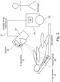
- Fig. 1 shows the basic working principle of a mobile X-ray machine 10.
- the technician places an X-ray detector 12 behind a patient, shown as bed-patient in fig. 1 .
- the technician manually sets the position of an X-ray emitter 14 so that the desired field of view can be captured by the X-ray detector 12.
- the technician acquires an image by activating the X-ray emitter 14.
- the position of X-ray detector 12 e.g., coordinates and rotation angles
- the position of the X-ray emitter e.g., distance to patient, rotation angles, and voltage
- US2020/0085385Al relates to generating a positioning signal to facilitate positioning of one or more of a patient, X-ray source, or detector during an image acquisition
- a computer-implemented method for determining a position of an X-ray emitter of a mobile X-ray device comprising:
- the present disclosure proposes a method that can automatically locate the optimal X-ray emitter position for an image using either a reference X-ray image, such as a prior high-quality image from the same patient or a reference image from an atlas, deemed suitable for this imaging case.
- a reduction of the radiation dose received by the patients may be achieved by lowering the number of retakes.
- reduced turnaround times may be achieved by avoiding low quality images being send to the PACS and rejected at the time of their review.
- the costs may also be reduced.
- the step of generating a virtual X-ray image of the internal body structure further comprises:
- the camera comprises a three-dimensional (3D) camera and/or a two-dimensional (2D) camera.
- the distance from the X-ray emitter to the patient is determined based on depth information in the camera-acquired image or a neural network based depth estimation.
- the step of registering the virtual X-ray image of the internal body structure with the reference X-ray image of the internal body structure further comprises:
- the at least one parameter for adjusting the position of the X-ray emitter includes one or more of:
- the computer-implemented method further comprises:
- the computer-implemented method further comprises:
- the reference X-ray image comprises one or more of:
- an X-ray emitter position determination device comprising a processing unit configured to perform the steps of the method according to the first aspect and any associated example.
- an X-ray imaging system comprising:
- the tracker device comprises one or more of: a marker device, a gyroscope, and an antenna.
- the mobile X-ray device further comprises a mobile X-ray robotic arm to support the X-ray emitter.
- the X-ray emitter position determination device is configured to provide a control signal to control the mobile X-ray robotic arm of the mobile X-ray device to adjust the position of the X-ray emitter.
- the mobile X-ray device further comprises a display configured to display an instruction provided by the X-ray emitter position determination device to guide a user to manually adjust the position of the X-ray emitter.
- the predicted directions are used on the X-ray machine: they either can be displayed for the manual correction by the technician, or an automated correction by a mobile X-ray robotic arm (if present) can be realized.
- a computer program product comprising instructions which, when the program is executed by a processing unit, cause the processing unit to carry out the steps of the method disclosed herein.
- a computer-readable medium having stored thereon the computer program product.
- mobile X-ray systems may be limited in terms of image quality compared to their stationary counterparts, i.e., bad field of view, missed or cut anatomy. Bad images may lead to image retakes, which increase the radiation dose for the patient.
- a method, apparatus, and system are provided with the aim of improving the image quality and overcoming one or more of the above-mentioned problems of mobile X-ray during the image acquisition stage.
- a system is proposed that can automatically acquire mobile X-ray images of better quality.
- the system disclosed herein may automatically locate the optimal X-ray emitter position for an image using either a prior high-quality image from the same patient, or a reference image from an atlas, deemed suitable for this imaging case.
- Fig. 2 illustrates an exemplary X-ray imaging system 100 according to an embodiment of the present invention.
- the X-ray imaging system 100 comprises a mobile X-ray device 10 with an X-ray emitter 14.
- the mobile X-ray device 10 further comprises a chassis 16 that supports an arm, e.g., a robotic arm 18, and having a system with wheels 20 for manual or motorized movement which allow the equipment to be transported.
- the robotic arm 18 may move horizontally and/or vertically and support at its end a head assembly 22, where the X-ray emitter 14 is located.
- the X-ray imaging system 100 further comprises a camera 24 mountable to the mobile X-ray device 10 and configured to capture a camera-acquired image from a patient in an X-ray imaging session.
- the camera 24 is registered to an origin of the X-ray emitter 14.
- the camera 24 may be located in the head assembly 22.
- the camera 24 may be an embedded camera.
- the camera 24 may be removably mounted to the head assembly 22.
- the camera 24 may be a two-dimensional (2D) camera configured for capturing one scene by using one photographing lens and one image sensor. The obtained image is called a 2D image.
- the camera 24 may be a three-dimensional (3D) camera for capturing 3D images.
- the 3D camera may be a range camera, which produces a 2D image showing the distance to points in a scene from a specific point.
- the 3D camera may be e.g., a stereo camera, which is a type of camera with two or more lenses with separate image sensors or film frame for each lens.
- the X-ray imaging system 100 shown in Fig. 2 further comprises a portable X-ray detector 12, which may be arranged behind a patient in order to measure the flux, spatial distribution, spectrum, and/or other properties of X-rays.
- the portable X-ray detector 12 may be fitted with a tracker device 26, such as a gyroscope, antennas, a marker or other devices, which help to localize the portable X-ray detector's position relative to the X-ray emitter 14.
- the X-ray imaging system 100 shown in Fig. 2 further comprises an X-ray emitter position determination device 30 configured to determine at least one parameter to adjust a position of the X-ray emitter 14.
- the X-ray emitter position determination device 30 may comprise various physical and/or logical components for communicating and manipulating information, which may be implemented as hardware components (e.g., computing devices, processors, logic devices), executable computer program instructions (e.g., firmware, software) to be executed by various hardware components, or any combination thereof, as desired for a given set of design parameters or performance constraints.
- the X-ray emitter position determination device 30 may be embodied as, or in, a device, such as the mobile X-ray device 10 shown in Fig. 2 or mobile device.
- the X-ray emitter position determination device 30 may comprise one or more microprocessors or computer processors, which execute appropriate software.
- the processing unit of the apparatus 10 may be embodied by one or more of these processors.
- the software may have been downloaded and/or stored in a corresponding memory, e.g., a volatile memory such as RAM or a non-volatile memory such as flash.
- the software may comprise instructions configuring the one or more processors to perform the functions as described herein.
- the X-ray emitter position determination device 30 may be implemented with or without employing a processor, and also may be implemented as a combination of dedicated hardware to perform some functions and a processor (e.g., one or more programmed microprocessors and associated circuitry) to perform other functions.
- the functional units of the X-ray emitter position determination device 30 may be implemented in the device or apparatus in the form of programmable logic, e.g., as a Field-Programmable Gate Array (FPGA).
- FPGA Field-Programmable Gate Array
- each functional unit of the apparatus may be implemented in the form of a circuit.
- Fig. 2 may show that the X-ray emitter position determination device 30 is embodied in the mobile X-ray device 10, it will be appreciated that in some implementations the X-ray emitter position determination device 30 may be embodied as, or in, a mobile device, e.g., tablet computer.
- the X-ray emitter position determination device 30 is configured to perform the method disclosed herein. The method will be described in detail hereinafter and in conjunction with the flowchart shown in Fig. 3 .
- Fig. 3 illustrates a flowchart describing a computer-implemented method 200 for determining a position of an X-ray emitter of a mobile X-ray device.
- the method 200 may be implemented as a device, module or related component in a set of logic instructions stored in a nontransitory machine- or computer-readable storage medium such as random access memory (RAM), read only memory (ROM), programmable ROM (PROM), firmware, flash memory, etc., in configurable logic such as, for example, programmable logic arrays (PLAs), field programmable gate arrays (FPGAs), complex programmable logic devices (CPLDs), in fixed-functionality hardware logic using circuit technology such as, for example, application specific integrated circuit (ASIC), complementary metal oxide semiconductor (CMOS) or transistor-transistor logic (TTL) technology, or any combination thereof.
- PLAs programmable logic arrays
- FPGAs field programmable gate arrays
- CPLDs complex programmable logic devices
- ASIC application specific integrated circuit
- computer program code to carry out operations shown in the method 200 may be written in any combination of one or more programming languages, including an object oriented programming language such as JAVA, SMALLTALK, C++, Python, or the like and conventional procedural programming languages, such as the "C" programming language or similar programming languages.
- object oriented programming language such as JAVA, SMALLTALK, C++, Python, or the like
- conventional procedural programming languages such as the "C" programming language or similar programming languages.
- the exemplary method may be implemented as the apparatus 30 shown in Fig. 2 .
- the method 200 comprises a step of receiving (i) a camera-acquired image originating from a camera that monitors a patient in an X-ray imaging session, wherein the camera is registered to an origin of the X-ray emitter, (ii) a reference X-ray image of an internal body structure to be examined in the X-ray examination, and (iii) position information of an X-ray detector.
- the camera-acquired image may originate from the camera 24 shown in Fig. 2 that monitors the patient in an X-ray imaging session.
- the camera 24 may be a video camera configured to send the real-time video stream to the apparatus 30, which may have a videoprocessing unit to process the real-time video stream.
- the camera 24 may be a camera configured to capture images and send the images to the apparatus 30, which may have an imageprocessing unit to process the images.
- the camera-acquired image may comprise one or more 3D images.
- the camera-acquired image may comprise one or more 2D images.
- Fig. 4 illustrates an exemplary registration process.
- an object When an object is imaged, its representation is stored in a matrix of pixels, which can be addressed by their coordinates x, y.
- the origin i.e., the 0, 0 point
- the origin is located in the upper left corner of the matrix, with the x axis going from left to right, and the y axis from top to bottom.
- imaging the object twice will result in two different matrices, with two different coordinate systems.
- the nose of the patient on image "a” is located further on the right and down, than on image "b".
- the reference X-ray image of an internal body structure to be examined in the X-ray examination may be downloaded from a Picture Archiving and Communication System (PACS).
- the reference X-ray image may be a previous scan of the patient of a good quality or some reference image or atlas of a good quality.
- the reference X-ray image may be acquired from a different patient.
- the position information of an X-ray detector 12 may be acquired from the tracker device 26, e.g., a marker device, a gyroscope, an antenna, or any combination thereof, which is attached to the X-ray detector 12.
- the method 200 further comprises a step of detecting and localizing a plurality of anatomical landmarks in the camera-acquired image.
- a model of the patient may be determined prior to imaging in order to conform the imaging parameters to the patient anatomy.
- the model may include locations of anatomical landmarks, such as shoulders, pelvis, torso, knees, etc.
- An acquired surface image of a patient may be compared against a library of pre-modeled surface images to determine a model corresponding to the patient. The determination may be performed by a neural network which is trained based on the library of pre-modeled surface images.
- the location of a head, shoulder, torso, knee, and ankle may be determined based on a 2D or 3D image.
- Neural networks may be trained to detect the landmarks automatically. For example, supervised learning can be applied for anatomical landmark localization. See for example Gite, S., Mishra, A., & Kotecha, K. (2022). Enhanced lung image segmentation using deep learning. Neural Computing and Applications, 1-15 .
- the method 200 further comprises a step of determining a distance from the X-ray emitter to the patient based on the camera-acquired image. If the camera is a 3D camera, the distance from the X-ray emitter to the patient may be determined based on depth information in the camera-acquired image. If the camera is a 2D camera, the distance from the X-ray emitter to the patient may be determined based on a neural network based depth estimation. For example, self-supervised learning may be applied for the distance or depth estimation. See for example Bian, J., Li, Z., Wang, N., Zhan, H., Shen, C., Cheng, M. M., & Reid, I. (2019). Unsupervised scale-consistent depth and egomotion learning from monocular video. Advances in neural information processing systems, 32 .
- the method 200 further comprises a step of generating a virtual X-ray image of the internal body structure based on the plurality of detected anatomical landmarks, the distance from the X-ray emitter to the patient, and the position information of the X-ray detector.
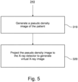
- Fig. 5 shows a flow diagram describing one implementation of step 240.
- step 310 of step 240 a pseudo density image of the patient is generated based on the plurality of detected anatomical landmarks.
- step 320 of step 240 the pseudo density image of the patient is projected to the X-ray detector based on a camera position of the camera, the distance from the X-ray emitter to the patient, and position information of the X-ray detector using a cone-beam projection to obtain the virtual X-ray image of the internal body structure.
- a virtual X-ray image may be generated in two steps.
- Frist anatomical landmarks are used to produce a pseudo density image of the patient e.g., by a neural network.
- a neural network can be trained using annotated pairs of images, e.g., CT images and the corresponding masks.
- the neural network may be a convolutional network.
- Adversarial training may be used to train this model. See for example Park, T., Liu, M. Y., Wang, T. C., & Zhu, J. Y. (2019). Semantic image synthesis with spatially-adaptive normalization. In Proceedings of the IEEE/CVF conference on computer vision and pattern recognition (pp. 2337-2346 ).
- the resulted pseudo density image is then projected to the detector given the camera position, distance to patient, and the relative detector position using cone-beam projection.
- the obtained image is a virtual X-ray image.
- the method 200 further comprises a step of registering the virtual X-ray image of the internal body structure with the reference X-ray image of the internal body structure
- a pre-trained neural network may be applied to register the virtual X-ray image of the internal body structure with the reference X-ray image of the internal body structure.
- the pre-trained neural network has been trained to generate a residual parameter of a camera position of the camera from the virtual X-ray image, the reference X-ray image, and the plurality of detected anatomical landmarks.
- the residual parameter of the camera position is usable to transform the virtual X-ray image to the reference X-ray image.
- a neural network may have been trained in the following way.
- the neural network takes three inputs: a reference X-ray image, a virtual X-ray image, and an anatomical landmarks map.
- the output of the model is a residual parameter of the camera position.
- Such parameters can be applied to transform virtual image towards reference image.
- the required images for training are artificially sampled from pseudo CT projects using static detector parameters and flexible emitter.
- the registration results are used to predict the directions on how to adjust the emitter's position.
- the neural network may be a convolutional network. Self-supervised learning can be applied to train this model. See for example Dalca, A. V., Balakrishnan, G., Guttag, J., & Sabuncu, M. R. (2018, September). Unsupervised learning for fast probabilistic diffeomorphic registration. In International Conference on Medical Image Computing and Computer-Assisted Intervention (pp. 729-738). Springer, Cham.
- the method 200 further comprises a step of determining at least one parameter to adjust the position of the X-ray emitter based on a result of registration.
- the registration results are used to predict the directions on how to adjust the emitter's position.
- the at least one parameter may include one or more of a parameter for adjusting the distance from the X-ray emitter to the patient and a parameter for adjusting a rotation angle of the X-ray emitter.
- the apparatus 30 may provide, based on the at least one determined parameter, an instruction signal to guide a user to manually adjust the position of the X-ray emitter.
- the instruction signal may be a voice signal for guiding a technician to manually correct the position of the X-ray emitter.
- the instruction signals may be a displayed instruction used to guide a technician to manually correct the position of the X-ray emitter.
- the apparatus 30 may provide based on the at least one determined parameter, a control signal usable to control a mobile X-ray robotic arm 18 of the mobile X-ray device 10 to adjust the position of the X-ray emitter 14.
- Fig. 6 shows an exemplary working principle of the exemplary X-ray imaging system 100 shown in Fig. 2 .
- the mobile X-ray machine 10 is placed in front of the patient (indicated with "a").
- the X-ray detector 12 is placed behind the patient.
- the technician may download from the PACS a reference X-ray image (indicated with "b"). It may be a previous scan of a good quality or some reference image or atlas of a good quality.
- the reference X-ray image is provided to the apparatus 30.
- the camera 24 sends a camera-acquired image, e.g., the real-time video stream or images, to the apparatus 30.
- the apparatus 30 may comprise a first neural network, also referred to as neural network A, to predict anatomical landmarks and the distance to the patient (indicated with "c") based on the camera-acquired image in the patient video.
- a first neural network also referred to as neural network A
- neural network A to predict anatomical landmarks and the distance to the patient (indicated with "c") based on the camera-acquired image in the patient video.
- the apparatus 30 may comprise a second neural network, also referred to as neural network B, to predict a virtual X-ray image using the anatomical landmarks (indicated with “d") and the X-ray emitter (indicated with "f") and detector position (indicated with “e”).
- a virtual X-ray image is generated in two steps. 3D anatomical landmarks from neural network A are being used to produce a pseudo density image of the patient by neural network B.
- Such network can be trained using annotated pairs of images, e.g., CT images and the corresponding masks.
- the resulted pseudo density image is being projected to the detector given the camera position, distance to patient, and the relative detector position using cone-beam projection.
- the obtained image is a virtual X-ray image.
- the apparatus 30 may comprise a third neural network, also referred to as neural network C, to register the virtual X-ray (indicated with "h") with the reference X-ray image (indicated with "i") using the anatomical landmarks (indicated with "g”).
- the neural network C has been trained in the following way. It takes three inputs: a reference X-ray image, a virtual X-ray image and an anatomical landmarks map. The output of the model is a residual parameter of the camera position. Such parameters can be applied to transform virtual image towards reference image.
- the required images for training are artificially sampled from pseudo CT projects using static detector parameters and flexible emitter parameters. The registration results are used to predict the directions on how to adjust the emitter's position.
- the predicted directions are used on the X-ray machine: they either can be displayed for the manual correction by the technician, or an automated correction by a mobile X-ray robotic arm (if present) can be realized.
- the method, apparatus, and system as disclosed herein can automatically locate an optimal X-ray emitter position for an image using either a prior high-quality image from the same patient, or a reference image from an atlas, deemed suitable for this imaging case, and can automatically acquire mobile X-ray images of better quality.
- the method, apparatus, and system as disclosed herein may lower the number of retakes and therefore achieve a reduction of the radiation dose received by the patients.
- the method, apparatus, and system as disclosed herein may avoid low quality images being sent to the PACs and rejected at the time of the review and therefore achieve reduced turnaround times.
- the method, apparatus, and system as disclosed herein may also reduce costs, because of the multiple job repetitions may be reduced.
- a computer program or a computer program element is provided that is characterized by being adapted to execute the method steps of the method according to one of the preceding sfs45kk, on an appropriate system.
- the computer program element might therefore be stored on a computer unit, which might also be part of an embodiment of the present invention.
- This computing unit may be adapted to perform or induce a performing of the steps of the method described above. Moreover, it may be adapted to operate the components of the above described apparatus.
- the computing unit can be adapted to operate automatically and/or to execute the orders of a user.
- a computer program may be loaded into a working memory of a data processor.
- the data processor may thus be equipped to carry out the method of the invention.
- This exemplary embodiment of the invention covers both, a computer program that right from the beginning uses the invention and a computer program that by means of an up-date turns an existing program into a program that uses the invention.
- the computer program element might be able to provide all necessary steps to fulfil the procedure of an exemplary embodiment of the method as described above.
- a computer readable medium such as a CD-ROM
- the computer readable medium has a computer program element stored on it which computer program element is described by the preceding section.
- a computer program may be stored and/or distributed on a suitable medium, such as an optical storage medium or a solid state medium supplied together with or as part of other hardware, but may also be distributed in other forms, such as via the internet or other wired or wireless telecommunication systems.
- a suitable medium such as an optical storage medium or a solid state medium supplied together with or as part of other hardware, but may also be distributed in other forms, such as via the internet or other wired or wireless telecommunication systems.
- the computer program may also be presented over a network like the World Wide Web and can be downloaded into the working memory of a data processor from such a network.
- a medium for making a computer program element available for downloading is provided, which computer program element is arranged to perform a method according to one of the previously described embodiments of the invention.
Landscapes
- Health & Medical Sciences (AREA)
- Life Sciences & Earth Sciences (AREA)
- Medical Informatics (AREA)
- Engineering & Computer Science (AREA)
- Radiology & Medical Imaging (AREA)
- Biomedical Technology (AREA)
- Biophysics (AREA)
- Nuclear Medicine, Radiotherapy & Molecular Imaging (AREA)
- Optics & Photonics (AREA)
- Pathology (AREA)
- Physics & Mathematics (AREA)
- High Energy & Nuclear Physics (AREA)
- Heart & Thoracic Surgery (AREA)
- Molecular Biology (AREA)
- Surgery (AREA)
- Animal Behavior & Ethology (AREA)
- General Health & Medical Sciences (AREA)
- Public Health (AREA)
- Veterinary Medicine (AREA)
- Apparatus For Radiation Diagnosis (AREA)
Claims (14)
- Computerimplementiertes Verfahren zum Bestimmen einer Position eines Röntgenstrahlers einer mobilen Röntgenvorrichtung, umfassend:- Empfangen (210) (i) eines von einer Kamera erfassten Bildes, das von einer Kamera stammt, die einen Patienten in einer Röntgenbildgebungssitzung überwacht, wobei die Kamera auf einen Ursprung des Röntgenstrahlers registriert ist, (ii) eines Referenz-Röntgenbildes einer bei der Röntgenuntersuchung zu untersuchenden inneren Körperstruktur, und (iii) von Positionsinformationen eines Röntgendetektors;- Detektieren (220) und Lokalisieren einer Vielzahl von anatomischen Orientierungspunkten in dem von der Kamera erfassten Bild;- Bestimmen (230) eines Abstands vom Röntgenstrahler zum Patienten basierend auf dem von der Kamera erfassten Bild;gekennzeichnet durch- Generieren (240) eines virtuellen Röntgenbildes der inneren Körperstruktur basierend auf der Vielzahl von detektierten anatomischen Orientierungspunkten, dem Abstand vom Röntgenstrahler zum Patienten und den Positionsinformationen des Röntgendetektors;- Erzeugen (310) eines Pseudodichtebildes des Patienten basierend auf der Vielzahl von detektierten anatomischen Orientierungspunkten; und- Projizieren (320) des Pseudodichtebildes des Patienten auf den Röntgendetektor basierend auf einer Kameraposition der Kamera, dem Abstand vom Röntgenstrahler zum Patienten und von Positionsinformationen des Röntgendetektors unter Verwendung einer Kegelstrahlprojektion, um das virtuelle Röntgenbild der inneren Körperstruktur zu erhalten,- Registrieren (250) des virtuellen Röntgenbildes der inneren Körperstruktur mit dem Referenz-Röntgenbild der inneren Körperstruktur; und- Bestimmen (260) mindestens eines Parameters, um die Position des Röntgenstrahlers basierend auf einem Registrierungsergebnis anzupassen.
- Computerimplementiertes Verfahren nach Anspruch 1,wobei die Kamera eine dreidimensionale, 3D-Kamera und eine zweidimensionale, 2D-Kamera umfasst; undwobei der Abstand vom Röntgenstrahler zum Patienten basierend auf Tiefeninformationen in dem von der Kamera erfassten Bild oder einer auf einem neuronalen Netzwerk basierenden Tiefenschätzung bestimmt wird.
- Computerimplementiertes Verfahren nach Anspruch 1 oder 2,
wobei der Schritt des Registrierens des virtuellen Röntgenbildes der inneren Körperstruktur mit dem Referenz-Röntgenbild der inneren Körperstruktur weiter umfasst:- Anwenden eines vorab trainierten neuronalen Netzwerks, um das virtuelle Röntgenbild der inneren Körperstruktur mit dem Referenz-Röntgenbild der inneren Körperstruktur zu registrieren, wobei das vorab trainierte neuronale Netzwerk trainiert worden ist, um einen Restparameter einer Kameraposition der Kamera aus dem virtuellen Röntgenbild, dem Referenz-Röntgenbild und der Vielzahl von detektierten anatomischen Orientierungspunkten zu generieren, wobei der Restparameter der Kameraposition verwendbar ist, um das virtuelle Röntgenbild in das Referenz-Röntgenbild umzuwandeln. - Computerimplementiertes Verfahren nach einem der vorstehenden Ansprüche,
wobei der mindestens eine Parameter zum Anpassen der Position des Röntgenstrahlers eines oder mehr beinhaltet von:- einem Parameter zum Anpassen des Abstands vom Röntgenstrahler zum Patienten; und- einem Parameter zum Anpassen eines Drehwinkels des Röntgenstrahlers. - Computerimplementiertes Verfahren nach einem der vorstehenden Ansprüche, weiter umfassend:- Bereitstellen, basierend auf dem mindestens einen bestimmten Parameter, eines Anweisungssignals, um einen Benutzer zu führen, um die Position des Röntgenstrahlers manuell anzupassen.
- Computerimplementiertes Verfahren nach einem der vorstehenden Ansprüche, weiter umfassend:- Bereitstellen, basierend auf dem mindestens einen bestimmten Parameter, eines Steuersignals, das verwendbar ist, um einen mobilen Röntgenroboterarm der mobilen Röntgenvorrichtung zu steuern, um die Position des Röntgenstrahlers anzupassen.
- Computerimplementiertes Verfahren nach einem der vorstehenden Ansprüche, wobei das Referenz-Röntgenbild eines oder mehr umfasst von:- einem zuvor vom Patienten erfassten Röntgenbild der inneren Körperstruktur; und- einem Referenz-Röntgenbild aus einem Atlas.
- Röntgenstrahler-Positionsbestimmungsvorrichtung (30), die eine Verarbeitungseinheit umfasst, die konfiguriert ist, um die Schritte des Verfahrens nach einem der vorstehenden Ansprüche durchzuführen.
- Röntgenbildgebungssystem (100), umfassend:- eine mobile Röntgenvorrichtung (10) die einen Röntgenstrahler (14) umfasst;- eine Kamera (24), die an der mobilen Röntgenvorrichtung montierbar ist und konfiguriert ist, um in einer Röntgenbildgebungssitzung ein von einer Kamera erfasstes Bild eines Patienten aufzunehmen, wobei die Kamera auf einen Ursprung des Röntgenstrahlers registriert ist;- einen Röntgendetektor (12);- eine Trackervorrichtung (26), die an dem Röntgendetektor anbringbar, oder in den Röntgendetektor eingebettet ist und konfiguriert ist, um Positionsinformationen des Röntgendetektors bereitzustellen; und- die Röntgenstrahler-Positionsbestimmungsvorrichtung nach Anspruch 8, die konfiguriert ist, um mindestens einen Parameter zu bestimmen, um eine Position des Röntgenstrahlers anzupassen.
- Röntgenbildgebungssystem nach Anspruch 9,
wobei die Trackervorrichtung eines oder mehr umfasst von:- einer Markierungsvorrichtung;- einem Gyroskop; und- einer Antenne. - Röntgenbildgebungssystem nach Anspruch 9 oder 10,wobei die mobile Röntgenvorrichtung weiter einen mobilen Röntgenroboterarm umfasst, um den Röntgenstrahler zu tragen; undwobei die Röntgenstrahler-Positionsbestimmungsvorrichtung konfiguriert ist, um ein Steuersignal bereitzustellen, um den mobilen Röntgenroboterarm der mobilen Röntgenvorrichtung zu steuern, um die Position des Röntgenstrahlers anzupassen.
- Röntgenbildgebungssystem nach einem der Ansprüche 9 bis 11. weiter umfassend:- eine Anzeige, die konfiguriert ist, um eine von der Positionsbestimmungsvorrichtung eines Röntgenstrahlers bereitgestellte Anweisung anzuzeigen, um einen Benutzer zu führen, um die Position des Röntgenstrahlers manuell anzupassen.
- Computerprogrammprodukt, das Anweisungen umfasst, die, wenn das Programm von einer Verarbeitungseinheit ausgeführt wird, die Verarbeitungseinheit veranlassen, die Schritte des Verfahrens nach einem der Ansprüche 1 bis 7 auszuführen.
- Computerlesbares Medium, auf dem das Computerprogrammprodukt nach Anspruch 13 gespeichert ist.
Applications Claiming Priority (2)
| Application Number | Priority Date | Filing Date | Title |
|---|---|---|---|
| RU2022133850 | 2022-12-22 | ||
| PCT/EP2023/085463 WO2024132731A1 (en) | 2022-12-22 | 2023-12-13 | Automatic optimal x-ray emitter position detection for mobile x-ray devices |
Publications (2)
| Publication Number | Publication Date |
|---|---|
| EP4447810A1 EP4447810A1 (de) | 2024-10-23 |
| EP4447810B1 true EP4447810B1 (de) | 2025-04-30 |
Family
ID=89222263
Family Applications (1)
| Application Number | Title | Priority Date | Filing Date |
|---|---|---|---|
| EP23822371.3A Active EP4447810B1 (de) | 2022-12-22 | 2023-12-13 | Automatische optimale röntgenstrahlerpositionsdetektion für mobile röntgenvorrichtungen |
Country Status (4)
| Country | Link |
|---|---|
| EP (1) | EP4447810B1 (de) |
| JP (1) | JP2026500176A (de) |
| CN (1) | CN118613217B (de) |
| WO (1) | WO2024132731A1 (de) |
Family Cites Families (6)
| Publication number | Priority date | Publication date | Assignee | Title |
|---|---|---|---|---|
| EP2747661B1 (de) * | 2011-11-18 | 2019-06-26 | Koninklijke Philips N.V. | Führungssystem für röntgenbildgebung zur positionierung eines patienten |
| US10213623B2 (en) * | 2016-05-04 | 2019-02-26 | Brainlab Ag | Monitoring a patient's position using a planning image and subsequent thermal imaging |
| US10918346B2 (en) * | 2017-09-06 | 2021-02-16 | General Electric Company | Virtual positioning image for use in imaging |
| US10568602B2 (en) * | 2017-09-06 | 2020-02-25 | General Electric Company | Virtual positioning image for use in imaging |
| EP3501400B1 (de) * | 2017-12-20 | 2022-06-08 | Siemens Healthcare GmbH | Verfahren und vorrichtung zur sicherstellung einer korrekten positionierung für eine radiographieaufnahme |
| DE102019214302B4 (de) * | 2019-09-19 | 2021-05-20 | Siemens Healthcare Gmbh | Verfahren zum Registrieren eines Röntgenbilddatensatzes mit einem Navigationssystem, Computerprogrammprodukt und System |
-
2023
- 2023-12-13 EP EP23822371.3A patent/EP4447810B1/de active Active
- 2023-12-13 CN CN202380018749.6A patent/CN118613217B/zh active Active
- 2023-12-13 JP JP2025532930A patent/JP2026500176A/ja active Pending
- 2023-12-13 WO PCT/EP2023/085463 patent/WO2024132731A1/en not_active Ceased
Also Published As
| Publication number | Publication date |
|---|---|
| CN118613217B (zh) | 2025-06-06 |
| CN118613217A (zh) | 2024-09-06 |
| WO2024132731A1 (en) | 2024-06-27 |
| JP2026500176A (ja) | 2026-01-06 |
| EP4447810A1 (de) | 2024-10-23 |
Similar Documents
| Publication | Publication Date | Title |
|---|---|---|
| US11253171B2 (en) | System and method for patient positioning | |
| EP3073926B1 (de) | Interventionelles röntgensystem mit automatischer isozentrierung | |
| CN107789001B (zh) | 一种用于成像扫描的摆位方法和系统 | |
| US10154823B2 (en) | Guiding system for positioning a patient for medical imaging | |
| US20200268251A1 (en) | System and method for patient positioning | |
| US20210212650A1 (en) | Method and systems for anatomy/view classification in x-ray imaging | |
| WO2019198394A1 (ja) | 医用画像処理装置、医用画像処理方法、およびプログラム | |
| EP4274502B1 (de) | Navigationsunterstützung | |
| JP6970203B2 (ja) | コンピュータ断層撮影および撮像されるべき解剖学的構造の位置決め | |
| EP4447810B1 (de) | Automatische optimale röntgenstrahlerpositionsdetektion für mobile röntgenvorrichtungen | |
| CN113693623B (zh) | 一种基于增强现实的超声扫查引导方法及系统 | |
| US10631948B2 (en) | Image alignment device, method, and program | |
| US11426136B2 (en) | X-ray diagnostic system and medical image diagnostic system | |
| JP2024543403A (ja) | 胸部x線撮像における肩甲骨ポジショニングの支援 | |
| US20240341601A1 (en) | Surgical positioning methods and methods for determining regions subject to radiation | |
| JP2024027651A (ja) | 情報処理装置、放射線撮影システム、情報処理方法及びプログラム | |
| EP4694772A1 (de) | Chirurgische positionierungsverfahren und verfahren zur bestimmung von regionen, die strahlung ausgesetzt sind | |
| CN120549519A (zh) | 图像处理方法以及医学成像系统 | |
| CN120770834A (zh) | 辅助摆位方法以及医学成像系统 | |
| CN117017490A (zh) | 用于医疗辅助的系统和方法 | |
| HK40014292B (zh) | 期望成像的解剖结构的定位和计算机断层摄影 | |
| HK40014292A (en) | Computed tomography and positioning of the anatomy desired to be imaged |
Legal Events
| Date | Code | Title | Description |
|---|---|---|---|
| STAA | Information on the status of an ep patent application or granted ep patent |
Free format text: STATUS: UNKNOWN |
|
| STAA | Information on the status of an ep patent application or granted ep patent |
Free format text: STATUS: THE INTERNATIONAL PUBLICATION HAS BEEN MADE |
|
| PUAI | Public reference made under article 153(3) epc to a published international application that has entered the european phase |
Free format text: ORIGINAL CODE: 0009012 |
|
| STAA | Information on the status of an ep patent application or granted ep patent |
Free format text: STATUS: THE APPLICATION HAS BEEN PUBLISHED |
|
| AK | Designated contracting states |
Kind code of ref document: A1 Designated state(s): AL AT BE BG CH CY CZ DE DK EE ES FI FR GB GR HR HU IE IS IT LI LT LU LV MC ME MK MT NL NO PL PT RO RS SE SI SK SM TR |
|
| STAA | Information on the status of an ep patent application or granted ep patent |
Free format text: STATUS: REQUEST FOR EXAMINATION WAS MADE |
|
| 17P | Request for examination filed |
Effective date: 20250102 |
|
| GRAP | Despatch of communication of intention to grant a patent |
Free format text: ORIGINAL CODE: EPIDOSNIGR1 |
|
| STAA | Information on the status of an ep patent application or granted ep patent |
Free format text: STATUS: GRANT OF PATENT IS INTENDED |
|
| DAV | Request for validation of the european patent (deleted) | ||
| DAX | Request for extension of the european patent (deleted) | ||
| GRAS | Grant fee paid |
Free format text: ORIGINAL CODE: EPIDOSNIGR3 |
|
| INTG | Intention to grant announced |
Effective date: 20250221 |
|
| RIN1 | Information on inventor provided before grant (corrected) |
Inventor name: STADELMANN, JOEL VALENTIN Inventor name: SIRAZITDINOV, ILYAS |
|
| GRAA | (expected) grant |
Free format text: ORIGINAL CODE: 0009210 |
|
| STAA | Information on the status of an ep patent application or granted ep patent |
Free format text: STATUS: THE PATENT HAS BEEN GRANTED |
|
| AK | Designated contracting states |
Kind code of ref document: B1 Designated state(s): AL AT BE BG CH CY CZ DE DK EE ES FI FR GB GR HR HU IE IS IT LI LT LU LV MC ME MK MT NL NO PL PT RO RS SE SI SK SM TR |
|
| REG | Reference to a national code |
Ref country code: CH Ref legal event code: EP Ref country code: GB Ref legal event code: FG4D |
|
| REG | Reference to a national code |
Ref country code: DE Ref legal event code: R084 Ref document number: 602023003231 Country of ref document: DE |
|
| REG | Reference to a national code |
Ref country code: IE Ref legal event code: FG4D |
|
| REG | Reference to a national code |
Ref country code: DE Ref legal event code: R096 Ref document number: 602023003231 Country of ref document: DE |
|
| REG | Reference to a national code |
Ref country code: GB Ref legal event code: 746 Effective date: 20250624 |
|
| REG | Reference to a national code |
Ref country code: NL Ref legal event code: MP Effective date: 20250430 |
|
| REG | Reference to a national code |
Ref country code: AT Ref legal event code: MK05 Ref document number: 1789271 Country of ref document: AT Kind code of ref document: T Effective date: 20250430 |
|
| PG25 | Lapsed in a contracting state [announced via postgrant information from national office to epo] |
Ref country code: PT Free format text: LAPSE BECAUSE OF FAILURE TO SUBMIT A TRANSLATION OF THE DESCRIPTION OR TO PAY THE FEE WITHIN THE PRESCRIBED TIME-LIMIT Effective date: 20250901 Ref country code: FI Free format text: LAPSE BECAUSE OF FAILURE TO SUBMIT A TRANSLATION OF THE DESCRIPTION OR TO PAY THE FEE WITHIN THE PRESCRIBED TIME-LIMIT Effective date: 20250430 Ref country code: ES Free format text: LAPSE BECAUSE OF FAILURE TO SUBMIT A TRANSLATION OF THE DESCRIPTION OR TO PAY THE FEE WITHIN THE PRESCRIBED TIME-LIMIT Effective date: 20250430 |
|
| REG | Reference to a national code |
Ref country code: LT Ref legal event code: MG9D |
|
| PG25 | Lapsed in a contracting state [announced via postgrant information from national office to epo] |
Ref country code: GR Free format text: LAPSE BECAUSE OF FAILURE TO SUBMIT A TRANSLATION OF THE DESCRIPTION OR TO PAY THE FEE WITHIN THE PRESCRIBED TIME-LIMIT Effective date: 20250731 Ref country code: NO Free format text: LAPSE BECAUSE OF FAILURE TO SUBMIT A TRANSLATION OF THE DESCRIPTION OR TO PAY THE FEE WITHIN THE PRESCRIBED TIME-LIMIT Effective date: 20250730 |
|
| PG25 | Lapsed in a contracting state [announced via postgrant information from national office to epo] |
Ref country code: NL Free format text: LAPSE BECAUSE OF FAILURE TO SUBMIT A TRANSLATION OF THE DESCRIPTION OR TO PAY THE FEE WITHIN THE PRESCRIBED TIME-LIMIT Effective date: 20250430 Ref country code: PL Free format text: LAPSE BECAUSE OF FAILURE TO SUBMIT A TRANSLATION OF THE DESCRIPTION OR TO PAY THE FEE WITHIN THE PRESCRIBED TIME-LIMIT Effective date: 20250430 |
|
| PG25 | Lapsed in a contracting state [announced via postgrant information from national office to epo] |
Ref country code: BG Free format text: LAPSE BECAUSE OF FAILURE TO SUBMIT A TRANSLATION OF THE DESCRIPTION OR TO PAY THE FEE WITHIN THE PRESCRIBED TIME-LIMIT Effective date: 20250430 |
|
| PG25 | Lapsed in a contracting state [announced via postgrant information from national office to epo] |
Ref country code: HR Free format text: LAPSE BECAUSE OF FAILURE TO SUBMIT A TRANSLATION OF THE DESCRIPTION OR TO PAY THE FEE WITHIN THE PRESCRIBED TIME-LIMIT Effective date: 20250430 |
|
| PG25 | Lapsed in a contracting state [announced via postgrant information from national office to epo] |
Ref country code: AT Free format text: LAPSE BECAUSE OF FAILURE TO SUBMIT A TRANSLATION OF THE DESCRIPTION OR TO PAY THE FEE WITHIN THE PRESCRIBED TIME-LIMIT Effective date: 20250430 |
|
| PG25 | Lapsed in a contracting state [announced via postgrant information from national office to epo] |
Ref country code: RS Free format text: LAPSE BECAUSE OF FAILURE TO SUBMIT A TRANSLATION OF THE DESCRIPTION OR TO PAY THE FEE WITHIN THE PRESCRIBED TIME-LIMIT Effective date: 20250731 |
|
| PG25 | Lapsed in a contracting state [announced via postgrant information from national office to epo] |
Ref country code: IS Free format text: LAPSE BECAUSE OF FAILURE TO SUBMIT A TRANSLATION OF THE DESCRIPTION OR TO PAY THE FEE WITHIN THE PRESCRIBED TIME-LIMIT Effective date: 20250830 |
|
| PG25 | Lapsed in a contracting state [announced via postgrant information from national office to epo] |
Ref country code: LV Free format text: LAPSE BECAUSE OF FAILURE TO SUBMIT A TRANSLATION OF THE DESCRIPTION OR TO PAY THE FEE WITHIN THE PRESCRIBED TIME-LIMIT Effective date: 20250430 |
|
| PG25 | Lapsed in a contracting state [announced via postgrant information from national office to epo] |
Ref country code: SM Free format text: LAPSE BECAUSE OF FAILURE TO SUBMIT A TRANSLATION OF THE DESCRIPTION OR TO PAY THE FEE WITHIN THE PRESCRIBED TIME-LIMIT Effective date: 20250430 Ref country code: DK Free format text: LAPSE BECAUSE OF FAILURE TO SUBMIT A TRANSLATION OF THE DESCRIPTION OR TO PAY THE FEE WITHIN THE PRESCRIBED TIME-LIMIT Effective date: 20250430 |
|
| PG25 | Lapsed in a contracting state [announced via postgrant information from national office to epo] |
Ref country code: CZ Free format text: LAPSE BECAUSE OF FAILURE TO SUBMIT A TRANSLATION OF THE DESCRIPTION OR TO PAY THE FEE WITHIN THE PRESCRIBED TIME-LIMIT Effective date: 20250430 |
|
| PG25 | Lapsed in a contracting state [announced via postgrant information from national office to epo] |
Ref country code: EE Free format text: LAPSE BECAUSE OF FAILURE TO SUBMIT A TRANSLATION OF THE DESCRIPTION OR TO PAY THE FEE WITHIN THE PRESCRIBED TIME-LIMIT Effective date: 20250430 |
|
| PG25 | Lapsed in a contracting state [announced via postgrant information from national office to epo] |
Ref country code: SK Free format text: LAPSE BECAUSE OF FAILURE TO SUBMIT A TRANSLATION OF THE DESCRIPTION OR TO PAY THE FEE WITHIN THE PRESCRIBED TIME-LIMIT Effective date: 20250430 |
|
| PG25 | Lapsed in a contracting state [announced via postgrant information from national office to epo] |
Ref country code: IT Free format text: LAPSE BECAUSE OF FAILURE TO SUBMIT A TRANSLATION OF THE DESCRIPTION OR TO PAY THE FEE WITHIN THE PRESCRIBED TIME-LIMIT Effective date: 20250430 |
|
| REG | Reference to a national code |
Ref country code: DE Ref legal event code: R097 Ref document number: 602023003231 Country of ref document: DE |
|
| PLBE | No opposition filed within time limit |
Free format text: ORIGINAL CODE: 0009261 |
|
| STAA | Information on the status of an ep patent application or granted ep patent |
Free format text: STATUS: NO OPPOSITION FILED WITHIN TIME LIMIT |
|
| REG | Reference to a national code |
Ref country code: CH Ref legal event code: L10 Free format text: ST27 STATUS EVENT CODE: U-0-0-L10-L00 (AS PROVIDED BY THE NATIONAL OFFICE) Effective date: 20260311 |
|
| PG25 | Lapsed in a contracting state [announced via postgrant information from national office to epo] |
Ref country code: RO Free format text: LAPSE BECAUSE OF FAILURE TO SUBMIT A TRANSLATION OF THE DESCRIPTION OR TO PAY THE FEE WITHIN THE PRESCRIBED TIME-LIMIT Effective date: 20250430 |
|
| 26N | No opposition filed |
Effective date: 20260202 |
|
| PGFP | Annual fee paid to national office [announced via postgrant information from national office to epo] |
Ref country code: DE Payment date: 20251229 Year of fee payment: 3 |