EP4447274A1 - Magnet arrangement for a rotor of an electric machine - Google Patents
Magnet arrangement for a rotor of an electric machine Download PDFInfo
- Publication number
- EP4447274A1 EP4447274A1 EP23167566.1A EP23167566A EP4447274A1 EP 4447274 A1 EP4447274 A1 EP 4447274A1 EP 23167566 A EP23167566 A EP 23167566A EP 4447274 A1 EP4447274 A1 EP 4447274A1
- Authority
- EP
- European Patent Office
- Prior art keywords
- magnet
- longitudinal direction
- rotor
- arrangement
- permanent magnet
- Prior art date
- Legal status (The legal status is an assumption and is not a legal conclusion. Google has not performed a legal analysis and makes no representation as to the accuracy of the status listed.)
- Pending
Links
- 238000004519 manufacturing process Methods 0.000 claims abstract description 19
- 238000003475 lamination Methods 0.000 claims description 7
- 238000000034 method Methods 0.000 claims description 2
- 230000003993 interaction Effects 0.000 description 3
- 230000000717 retained effect Effects 0.000 description 2
- 230000004888 barrier function Effects 0.000 description 1
- 230000001419 dependent effect Effects 0.000 description 1
- 239000000696 magnetic material Substances 0.000 description 1
- 238000004806 packaging method and process Methods 0.000 description 1
Images


Classifications
-
- H—ELECTRICITY
- H02—GENERATION; CONVERSION OR DISTRIBUTION OF ELECTRIC POWER
- H02K—DYNAMO-ELECTRIC MACHINES
- H02K1/00—Details of the magnetic circuit
- H02K1/06—Details of the magnetic circuit characterised by the shape, form or construction
- H02K1/22—Rotating parts of the magnetic circuit
- H02K1/27—Rotor cores with permanent magnets
- H02K1/2706—Inner rotors
- H02K1/272—Inner rotors the magnetisation axis of the magnets being perpendicular to the rotor axis
- H02K1/274—Inner rotors the magnetisation axis of the magnets being perpendicular to the rotor axis the rotor consisting of two or more circumferentially positioned magnets
- H02K1/2753—Inner rotors the magnetisation axis of the magnets being perpendicular to the rotor axis the rotor consisting of two or more circumferentially positioned magnets the rotor consisting of magnets or groups of magnets arranged with alternating polarity
- H02K1/276—Magnets embedded in the magnetic core, e.g. interior permanent magnets [IPM]
- H02K1/2766—Magnets embedded in the magnetic core, e.g. interior permanent magnets [IPM] having a flux concentration effect
Definitions
- the present invention relates to a magnet arrangement for a rotor of an electrical machine.
- the invention further relates to a method of manufacturing such a magnet arrangement.
- the invention relates to a rotor with at least one such magnet arrangement, an electrical machine with such a rotor and a motor vehicle with such an electrical machine.
- An electric machine has a rotor and a stator which interact electromagnetically during operation.
- the rotor of the electric machine may have at least one permanent magnet per pole.
- Corresponding electrical machines are known, for example, from US 2018/0145552 A1 and EP 2 348 613 A1 .
- one-piece permanent magnets are used, which are arranged at a distance from one another on the rotor in a rotationally fixed manner.
- the permanent magnets are cuboidal in shape.
- EP 2 348 613 A1 shows one-piece permanent magnets which converge at their end faces.
- the present invention is concerned with the problem of providing improved or at least other embodiments for a magnet arrangement for a rotor of an electrical machine, for a method for producing such a magnet arrangement, and for an electrical machine having such a rotor, and for a motor vehicle having such an electrical machine, which embodiments in particular eliminate disadvantages from the prior art.
- the present invention is concerned with the problem of providing embodiments for the magnet arrangement, for the method, for the rotor, for the electrical machine and for the motor vehicle which are characterized in particular by increased efficiency and/or increased performance.
- the present invention is based on the general idea of using in a rotor of an electric machine, instead of a one-piece permanent magnet per position, a magnet arrangement comprising two permanent magnets per position which rest on one another, the magnet arrangement being elongated in comparison with a cuboidal permanent magnet by means of an end face extending obliquely.
- the design and manufacture of the respective permanent magnet is simpler compared to the design and manufacture of an according one-piece permanent magnet. This leads to a simple manufacture and a simplified implementation of more complicated shapes.
- the two-part design allows an improved filling of the available space with magnetic material and thus leads to an improved efficiency of the corresponding electric machine.
- the magnet arrangement can be retained in a more effective way in the available space, in particular retained on a laminated sheets package of the rotor, leading to reduced stress in the lamination due to multitude of different bridge shapes/arrangements on the corresponding bridges. Due to the elongated structure of the magnet arrangement, in particular in comparison with a cuboidal structure, the magnetic field of the magnet arrangement is increased. As a consequence, a stronger electromagnetic interaction occurs during operation in an associated electrical machine. This leads to a further increased efficiency and an increased performance of the rotor as well as the associated electrical machine.
- the magnet arrangement thus comprises two permanent magnets, namely a first permanent magnet and a second permanent magnet.
- the respective permanent magnet has a contact surface and an outer surface facing away from the contact surface, which extend parallel in a direction.
- the direction is hereinafter also referred to as the longitudinal direction.
- the contact surface and the outer surface are spaced apart in a direction transverse to the longitudinal direction.
- the direction is also referred to hereinafter as the vertical direction.
- the contact surface has a length extending in the longitudinal direction, which is also referred to hereinafter as the contact length.
- the outer surface has a length extending in the longitudinal direction, which is also referred to hereinafter as the outer length.
- the contact length is greater than the outer length.
- the respective permanent magnet further has two end faces facing away from each other in the longitudinal direction.
- the end faces of the respective permanent magnet connect the associated contact surface to the associated outer surface. At least one of the end faces extends inwardly inclined relative to the longitudinal direction, so that the permanent magnet has a trapezoidal like shape in the region of the end face.
- the contact surfaces of the permanent magnets abut on each other.
- the "trapezoidal shape” or “trapezoidally inclined” correspond to the trapezoidal like shape in the region of the associated end face.
- Each permanent magnet preferably has a frustum like shape.
- each permanent magnet is shaped as a square frustum.
- Each permanent magnet is a magnet body, wherein the bodies are placed against each other at their contact surfaces.
- the permanent magnets of the magnet assembly are preferably manufactured separately and then placed against each other at their contact surfaces.
- the permanent magnets are arranged with regard to their magnetic poles in such a way that the magnet arrangement has the same polarity as a corresponding one-piece permanent magnet. Accordingly, in the following, identically formed or designed means the corresponding form of the permanent magnets or magnet arrangement and does not necessarily also refer to the magnet poles.
- the respective permanent magnet preferably has two side surfaces facing away from each other in a transverse direction, which extend in the longitudinal direction.
- the transverse direction extends transversely to the longitudinal direction and transversely to the vertical direction.
- the side surfaces of the respective permanent magnet thereby connect the contact surface and the outer surface of the associated permanent magnet to one another.
- the side surfaces advantageously connect the end faces of the associated permanent magnet to one another.
- the directions indicated with respect to the permanent magnets i.e. the longitudinal direction, the vertical direction and the transverse direction, each apply to the associated permanent magnet. In the magnet arrangement, these directions coincide. This means that the longitudinal direction and of both permanent magnets, the vertical direction of both permanent magnets and the directions of rotation of both permanent magnets correspond to each other respectively.
- the two permanent magnets of the magnet arrangement can have different shapes, in particular different sizes.
- the contact surfaces of the permanent magnets are of the same design. This results in simplified manufacture of the magnet arrangement and/or improved packaging in the associated rotor.
- the contact surfaces of the permanent magnets completely overlap in the transverse direction.
- Each permanent magnet in particular each surface and/or face, can have an arbitrary shape.
- at least one of the permanent magnets can have an asymmetric shape.
- the permanent magnets have the same shape.
- the manufacture of the magnet arrangement is simplified and/or cost reduced.
- the magnet arrangement can be formed symmetrically in a simplified manner in this way.
- only one of the end faces of the respective permanent magnet can be trapezoidally inclined inwards.
- both end faces of at least one of the permanent magnets are inclined inwardly relative to the longitudinal direction so that both end faces of the permanent magnet are trapezoidally shaped.
- the contact surface and the outer surface of at least one of the permanent magnets may be offset from each other in the longitudinal direction and/or in the transverse direction.
- the contact surface and the outer surface of at least one of the permanent magnets, preferably of the respective permanent magnet are centered relative to each other in the longitudinal direction, preferably further in the transverse direction. That is, the outer surface is centered relative to the contact surface in the longitudinal direction, preferably further in the transverse direction.
- At least one of the permanent magnets is formed symmetrically, i.e. shaped, with respect to a symmetry plane extending centrally in the longitudinal direction and along the vertical direction.
- both end faces of the permanent magnet are inclined inwardly with respect to the longitudinal direction.
- the outer surface is arranged centrally with respect to the contact surface in the longitudinal direction, preferably further in the transverse direction. If both permanent magnets are formed identically and the two contact surfaces overlap completely, this symmetry also applies to the magnet arrangement.
- the contact surfaces of the permanent magnets are in contact with each other but offset, for example in the longitudinal direction.
- the magnet arrangement is symmetrical with respect to a plane of symmetry of the arrangement extending between the contact surfaces and parallel to the contact surfaces.
- the side faces of the respective permanent magnet can in principle be of any shape.
- a cuboid-shaped magnetic magnet bar is preferably divided into successive permanent magnets by correspondingly oblique cuts. Also, at least two magnetic cuboid-shaped magnet bar can be arranged adjacent to one other to form a bar arrangement. The arrangement is divided into successive permanent magnets by correspondingly oblique cuts. Thus, no or at least reduced residues of the magnet bar are produced during the manufacture of the permanent magnets. This leads to reduced manufacturing costs and simplified production.
- At least one cuboid-shaped magnet bar is provided for producing the magnet arrangement, which magnet bar extends longitudinally in longitudinal direction. Alternating first cuts and second cuts are made in the at least one magnet bar, spaced apart from each other in the longitudinal direction. The first cuts and the second cuts are inclined relative to the longitudinal direction and are opposed to each other.
- a permanent magnet of the magnet assembly is produced by each two successive cuts in the respective at least one magnet bar. That is, spatially successive cuts are made to form the permanent magnets.
- the contact surface of a first one of the permanent magnets and a second one of the permanent magnets are placed abutting on each other, in particular attached.
- the magnet bars are preferably arranged adjacent one another vertically and thus transverse to the longitudinal direction.
- the successive cuts may be made subsequently or simultaneously.
- the scope of the present invention also includes a rotor for an electric machine having at least one such magnet assembly.
- the rotor comprises a shaft which, in operation, rotates about an axis of rotation which extends axially.
- the rotor further comprises at least one such magnet arrangement which is non-rotatable and thus torque proof with respect to the shaft.
- the respective magnet arrangement can be arranged in any desired manner with respect to the shaft, i.e. can extend in any desired manner relative to the shaft.
- the longitudinal direction of at least one of the magnet arrangements extends transversely or inclined to the axis of rotation.
- the rotor has at least two such magnet arrangements.
- the magnet arrangements are spaced apart from each other.
- at least two such magnet arrangements are spaced apart from each other surrounding the axis of rotation.
- the magnet arrangements are inclined or transverse relative to each other.
- the longitudinal direction of the magnet arrangements is inclined or transverse to each other.
- the non-rotatable attachment of the magnet arrangement in the rotor is advantageously realized via the at least one end face.
- an enlarged surface is available for the rotationally fixed attachment to the shaft. This leads to a simplified manufacture of the rotor as well as a more stable, rotationally fixed connection of the magnet arrangement. It is conceivable that the magnet arrangement is attached to the lamination of the rotor via the end faces.
- the rotor is used in an electric machine.
- the rotor interacts electromagnetically with a stator. During operation, the interaction leads to a rotation of the rotor around the axis of rotation.
- the rotor is advantageously arranged inside the stator.
- the electrical machine is thus in particular an "Interior Permanent Magnet Machine”, also known as an “IPM Machine”.
- the electric machine is preferably an electric motor.
- the electric machine especially the electric motor, can be used for any purpose.
- the electric motor can be designed as a traction motor.
- the electric motor is therefore used in particular for driving.
- the electric machine can serve any purpose.
- the rotor 31 is used in an electric machine 30 exemplary shown in Figures 6 and 7 .
- the electric machine 30 may be used in a motor vehicle 100 exemplary shown in Figure 8 .
- the magnet arrangement 1 is hereinafter also referred to as arrangement 1 for short.
- the arrangement 1 comprises 2 permanent magnets 2, 3, namely a first permanent magnet 2 and a second permanent magnet 3.
- the arrangement 1 is composed of the permanent magnets 2, 3.
- the respective permanent magnet 2, 3 has a contact surface 4, wherein the contact surfaces 4 of the permanent magnets 2, 3 abut on each other.
- the respective permanent magnet 2, 3 further comprises an outer surface 5 facing away from the associated contact surface 4.
- the contact surface 4 and the outer surface 5 extend in parallel in a direction 6, which will also be referred to hereinafter as longitudinal direction 6.
- the contact surface 4 and the outer surface 5 are spaced apart from each other in a direction 7 extending transversely to the longitudinal direction 6.
- the direction 7 is hereinafter also referred to as the vertical direction 7.
- the outer surface 5 and the contact surface 4 each have a length 8, 9 extending in the longitudinal direction 6.
- the length 8 of the outer surface 5 is hereinafter also referred to as the outer length 8.
- the length 9 of the contact surface 4 is also referred to hereinafter as the contact length 9.
- the contact length 9 is greater than the outer length 8. That is, the contact surface 4 is greater in the longitudinal direction 6 than the outer surface 5.
- the permanent magnet 2, 3 has two surfaces 10 facing away from each other in the longitudinal direction 6.
- the surfaces 10 are hereinafter also referred to as end faces 10.
- the respective end faces 10 connect the contact surface 4 and the outer surface 5 to each other.
- At least one of the end faces 10 extends inwardly inclined relative to the longitudinal direction 6, so that the permanent magnet 2, 3 is shaped trapezoidally in the region of the end face 10. This results in a trapezoidal shape in the side views shown in Figures 1 to 4 and 6 , or in a section along the longitudinal direction 6.
- a larger volume compared to a cuboid magnet results, so that the rotor 31 with the magnet arrangement 1 has an improved electromagnetic performance.
- both permanent magnets 2, 3 of the magnet arrangement 1 are formed identically in shape and have corresponding polarities, so that the magnet arrangement 1 is polarized in the manner of a one-piece permanent magnet (not shown).
- both end faces 10 of the respective permanent magnets 2, 3 of the magnet arrangement 1 are inclined inwardly, so that a trapezoidal shape is obtained in the region of both end faces 10.
- the outer surface 5 is arranged centrally with respect to the contact surface 4 in the longitudinal direction 6.
- a symmetrical configuration of the permanent magnet 2, 3 results with respect to a symmetry plane 12 of the respective permanent magnet 2, 3 extending centrally in the longitudinal direction 6 and running in the vertical direction 7.
- the symmetry plane 12 is also a symmetry plane 12 of the magnet arrangement 1.
- the magnet arrangement 1 comprises a further symmetry plane 11 extending between the contact surfaces 4 and parallel to the contact surfaces 4.
- the magnet arrangement 1 is symmetrical with respect to the symmetry plane 11 of the arrangement 1 extending between the contact surfaces 4 and parallel to the contact surfaces 4.
- the respective permanent magnet 2, 3 has two side faces 14 extending in the longitudinal direction 6 and facing away from each other in a transverse direction 13 extending transversely to the longitudinal direction 6 and transversely to the vertical direction 7.
- the side surfaces 14 of the respective permanent magnet 2, 3 each connect the contact surface 4 to the outer surface 5.
- the side surfaces 14 extend parallel in the vertical direction 7.
- the respective permanent magnet 2, 3 is cuboidal in shape.
- the magnet arrangement 1 can be manufactured in a simplified manner as shown in Figures 5 and 9 .
- at least one cuboid-shaped magnet bar 20 is provided, which extends longitudinally in longitudinal direction 6.
- cuts 21 are made in the at least one magnet bar 20 at intervals from one another in the longitudinal direction 6. More specifically alternating first cuts 21, 21a and second cuts 21, 21b are made in the at least one magnet bar 20 spaced apart from each other in the longitudinal direction 6.
- the first cuts 21, 21a and second cuts 21, 21b are inclined relative to the longitudinal direction 6 and run in opposite directions to each other. Consequently, a permanent magnet 2, 3 of the magnet arrangement 1 is manufactured by two spatially successive cuts 21 in the longitudinal direction 6. The successive cuts 21 can be made subsequently or simultaneous.
- a first permanent magnet 2 and a second permanent magnet 3 are attached to each other with their contact surfaces 9.
- the cuts 21 are made in a single magnet bar 20.
- the successive cuts 21, by way of example, are placed symmetrically.
- al the permanent magnets 2, 3 have the same shape and size.
- At least two cuboid-shaped magnet bars 20 are vertically arranged adjacent one another to form a bar arrangement 22.
- the bar arrangement 22 comprises at least two magnet bars 20 adjacent one another to transverse to their longitudinal extension.
- the first cuts 21, 21a and second cuts 21, 21b are made in the bar arrangement 22 at intervals from one another in the longitudinal direction 6 and thus successively, so that a permanent magnet 2, 3 of the magnet arrangement 1 is produced by the successive cuts 21 in the respective magnet bar 20.
- permanent magnets 2, 3 of different shapes and sizes are produced.
- the successive cuts 21, by way of example, are placed symmetrically using identical magnet bars 20.
- the rotor 31 comprises a lamination 35.
- the lamination 35 is non-rotatably attached to the rotor 31 and thus torque proof with the rotor 31.
- at least one such magnet arrangement 1 is non-rotatably attached to the lamination 35 and thus to the rotor 3.
- the rotor 31 has at least two such magnet arrangements 1.
- the magnet arrangements 1 are spaced apart from one another and, preferably evenly, surrounding the axis of rotation 36. In the view shown in Figure 7 two of the magnet arrangements 1 can be seen in a V configuration.
- the longitudinal directions 6 of the magnet arrangements 1 are inclined to each other and transverse or inclined to the axis of rotation 36.
- magnet arrangements 1 of the exemplary embodiment shown in Figure 1 are used by way of example.
- at least one magnet arrangement 1 of the exemplary embodiment of Figure 3 and/or of the exemplary embodiment of Figure 4 can also be used.
- the respective magnet arrangement 1 is laminated into the rotor 31 via the end faces 10 wherein the air pockets/magnet barriers are not shown for the clarity of the picture.
- the electrical machine 30 with the rotor 31 further comprises a stator 32.
- the stator 32 surrounds the rotor 31 in the shown exemplary embodiment.
- the stator 32 interacts electromagnetically with the rotor 31, in particular with the at least one magnet arrangement 1. The interaction is such that the rotor 31 rotates about the axis of rotation 36.
- the electric machine 30 is an electric motor 33.
- the electric motor 33 may be used for propulsion, i.e. may be a traction motor 34.
- the electric machine 30, in particular the electric motor 33 can be used in a motor vehicle 100.
- the electric motor 33 may serve to drive the motor vehicle 100, i.e. it may be a traction motor 34.
- the traction motor 34 drives at least one wheel 101 of the motor vehicle 100.
Landscapes
- Engineering & Computer Science (AREA)
- Power Engineering (AREA)
- Permanent Field Magnets Of Synchronous Machinery (AREA)
Abstract
The present invention relates to a magnet assembly (1) for a rotor (31) of an electric machine (30).Increased efficiency and performance are achieved in that the magnet arrangement (1) has two permanent magnets (2, 3) which bear against one another via contact surfaces (4), the respective permanent magnet (2, 3) being extended trapezoidally on one end face (10).The invention further relates to a method of manufacturing such a magnet assembly (1), a rotor (31) comprising such a magnet assembly, an electric machine (30) comprising such a rotor (31), and a motor vehicle (100) comprising such an electric machine (30).
Description
- The present invention relates to a magnet arrangement for a rotor of an electrical machine. The invention further relates to a method of manufacturing such a magnet arrangement. In addition, the invention relates to a rotor with at least one such magnet arrangement, an electrical machine with such a rotor and a motor vehicle with such an electrical machine.
- An electric machine has a rotor and a stator which interact electromagnetically during operation. For this purpose, the rotor of the electric machine may have at least one permanent magnet per pole.
- Corresponding electrical machines are known, for example, from
US 2018/0145552 A1 andEP 2 348 613 A1 . In each case, one-piece permanent magnets are used, which are arranged at a distance from one another on the rotor in a rotationally fixed manner. InUS 2018/0145552 A1 , the permanent magnets are cuboidal in shape.EP 2 348 613 A1 - The present invention is concerned with the problem of providing improved or at least other embodiments for a magnet arrangement for a rotor of an electrical machine, for a method for producing such a magnet arrangement, and for an electrical machine having such a rotor, and for a motor vehicle having such an electrical machine, which embodiments in particular eliminate disadvantages from the prior art. In particular, the present invention is concerned with the problem of providing embodiments for the magnet arrangement, for the method, for the rotor, for the electrical machine and for the motor vehicle which are characterized in particular by increased efficiency and/or increased performance.
- This problem is solved according to the invention by the subjects of the independent claims. Advantageous embodiments are the subject of the dependent claims.
- The present invention is based on the general idea of using in a rotor of an electric machine, instead of a one-piece permanent magnet per position, a magnet arrangement comprising two permanent magnets per position which rest on one another, the magnet arrangement being elongated in comparison with a cuboidal permanent magnet by means of an end face extending obliquely. The design and manufacture of the respective permanent magnet is simpler compared to the design and manufacture of an according one-piece permanent magnet. This leads to a simple manufacture and a simplified implementation of more complicated shapes. In addition, the two-part design allows an improved filling of the available space with magnetic material and thus leads to an improved efficiency of the corresponding electric machine. Furthermore, the magnet arrangement can be retained in a more effective way in the available space, in particular retained on a laminated sheets package of the rotor, leading to reduced stress in the lamination due to multitude of different bridge shapes/arrangements on the corresponding bridges. Due to the elongated structure of the magnet arrangement, in particular in comparison with a cuboidal structure, the magnetic field of the magnet arrangement is increased. As a consequence, a stronger electromagnetic interaction occurs during operation in an associated electrical machine. This leads to a further increased efficiency and an increased performance of the rotor as well as the associated electrical machine.
- In accordance with the idea of the invention, the magnet arrangement thus comprises two permanent magnets, namely a first permanent magnet and a second permanent magnet. The respective permanent magnet has a contact surface and an outer surface facing away from the contact surface, which extend parallel in a direction. The direction is hereinafter also referred to as the longitudinal direction. The contact surface and the outer surface are spaced apart in a direction transverse to the longitudinal direction. The direction is also referred to hereinafter as the vertical direction. The contact surface has a length extending in the longitudinal direction, which is also referred to hereinafter as the contact length. The outer surface has a length extending in the longitudinal direction, which is also referred to hereinafter as the outer length. Here, in the respective permanent magnet, the contact length is greater than the outer length. The respective permanent magnet further has two end faces facing away from each other in the longitudinal direction. The end faces of the respective permanent magnet connect the associated contact surface to the associated outer surface. At least one of the end faces extends inwardly inclined relative to the longitudinal direction, so that the permanent magnet has a trapezoidal like shape in the region of the end face. The contact surfaces of the permanent magnets abut on each other.
- In the following, the "trapezoidal shape" or "trapezoidally inclined" correspond to the trapezoidal like shape in the region of the associated end face.
- Each permanent magnet preferably has a frustum like shape. Preferably each permanent magnet is shaped as a square frustum.
- Each permanent magnet is a magnet body, wherein the bodies are placed against each other at their contact surfaces.
- The permanent magnets of the magnet assembly are preferably manufactured separately and then placed against each other at their contact surfaces.
- The permanent magnets are arranged with regard to their magnetic poles in such a way that the magnet arrangement has the same polarity as a corresponding one-piece permanent magnet. Accordingly, in the following, identically formed or designed means the corresponding form of the permanent magnets or magnet arrangement and does not necessarily also refer to the magnet poles.
- The respective permanent magnet preferably has two side surfaces facing away from each other in a transverse direction, which extend in the longitudinal direction. The transverse direction extends transversely to the longitudinal direction and transversely to the vertical direction. The side surfaces of the respective permanent magnet thereby connect the contact surface and the outer surface of the associated permanent magnet to one another. In addition, the side surfaces advantageously connect the end faces of the associated permanent magnet to one another.
- The directions indicated with respect to the permanent magnets, i.e. the longitudinal direction, the vertical direction and the transverse direction, each apply to the associated permanent magnet. In the magnet arrangement, these directions coincide. This means that the longitudinal direction and of both permanent magnets, the vertical direction of both permanent magnets and the directions of rotation of both permanent magnets correspond to each other respectively.
- In principle, the two permanent magnets of the magnet arrangement can have different shapes, in particular different sizes.
- In preferred embodiments, the contact surfaces of the permanent magnets are of the same design. This results in simplified manufacture of the magnet arrangement and/or improved packaging in the associated rotor.
- Preferably, the contact surfaces of the permanent magnets completely overlap in the transverse direction.
- Each permanent magnet, in particular each surface and/or face, can have an arbitrary shape. In particular, at least one of the permanent magnets can have an asymmetric shape.
- In preferred embodiments, the permanent magnets have the same shape. In particular, this means that the shapes of the two permanent magnets correspond to each other. As a consequence, the manufacture of the magnet arrangement is simplified and/or cost reduced. In addition, the magnet arrangement can be formed symmetrically in a simplified manner in this way.
- In principle, only one of the end faces of the respective permanent magnet can be trapezoidally inclined inwards.
- In preferred embodiments, both end faces of at least one of the permanent magnets, preferably of the respective permanent magnet, are inclined inwardly relative to the longitudinal direction so that both end faces of the permanent magnet are trapezoidally shaped.
- In principle, the contact surface and the outer surface of at least one of the permanent magnets may be offset from each other in the longitudinal direction and/or in the transverse direction.
- Preferably, the contact surface and the outer surface of at least one of the permanent magnets, preferably of the respective permanent magnet, are centered relative to each other in the longitudinal direction, preferably further in the transverse direction. That is, the outer surface is centered relative to the contact surface in the longitudinal direction, preferably further in the transverse direction.
- Advantageously, at least one of the permanent magnets, preferably the respective permanent magnet, is formed symmetrically, i.e. shaped, with respect to a symmetry plane extending centrally in the longitudinal direction and along the vertical direction. For this purpose, preferably both end faces of the permanent magnet are inclined inwardly with respect to the longitudinal direction. For this purpose, advantageously further, the outer surface is arranged centrally with respect to the contact surface in the longitudinal direction, preferably further in the transverse direction. If both permanent magnets are formed identically and the two contact surfaces overlap completely, this symmetry also applies to the magnet arrangement.
- It is conceivable that the contact surfaces of the permanent magnets are in contact with each other but offset, for example in the longitudinal direction.
- It is conceivable and preferred if the contact surfaces of the permanent magnets completely overlap.
- In preferred embodiments, the magnet arrangement is symmetrical with respect to a plane of symmetry of the arrangement extending between the contact surfaces and parallel to the contact surfaces.
- The side faces of the respective permanent magnet can in principle be of any shape.
- Preferred are embodiments in which the side surfaces of at least one of the permanent magnets, preferably of the respective permanent magnet, extend parallel in the vertical direction. This results in a shape of the permanent magnet with a cuboid-shaped base which is extended in the longitudinal direction by the trapezoidal region shaped by the at least one end face. This results in a simplified and cost-effective production of the permanent magnets and thus the magnet arrangement.
- For the production of the permanent magnets, a cuboid-shaped magnetic magnet bar is preferably divided into successive permanent magnets by correspondingly oblique cuts. Also, at least two magnetic cuboid-shaped magnet bar can be arranged adjacent to one other to form a bar arrangement. The arrangement is divided into successive permanent magnets by correspondingly oblique cuts. Thus, no or at least reduced residues of the magnet bar are produced during the manufacture of the permanent magnets. This leads to reduced manufacturing costs and simplified production.
- Consequently, it is preferred that at least one cuboid-shaped magnet bar is provided for producing the magnet arrangement, which magnet bar extends longitudinally in longitudinal direction. Alternating first cuts and second cuts are made in the at least one magnet bar, spaced apart from each other in the longitudinal direction. The first cuts and the second cuts are inclined relative to the longitudinal direction and are opposed to each other. Thus, a permanent magnet of the magnet assembly is produced by each two successive cuts in the respective at least one magnet bar. That is, spatially successive cuts are made to form the permanent magnets. To manufacture the magnet assembly, the contact surface of a first one of the permanent magnets and a second one of the permanent magnets are placed abutting on each other, in particular attached.
- In case two or more magnet bars are used, the magnet bars are preferably arranged adjacent one another vertically and thus transverse to the longitudinal direction.
- The successive cuts may be made subsequently or simultaneously.
- It is understood that the method of making the magnet assembly is also within the scope of the present invention.
- The scope of the present invention also includes a rotor for an electric machine having at least one such magnet assembly.
- The rotor comprises a shaft which, in operation, rotates about an axis of rotation which extends axially. The rotor further comprises at least one such magnet arrangement which is non-rotatable and thus torque proof with respect to the shaft.
- The respective magnet arrangement can be arranged in any desired manner with respect to the shaft, i.e. can extend in any desired manner relative to the shaft.
- In particular, it is conceivable that the longitudinal direction of at least one of the magnet arrangements extends transversely or inclined to the axis of rotation.
- Advantageously, the rotor has at least two such magnet arrangements. Preferably, the magnet arrangements are spaced apart from each other. In particular, at least two such magnet arrangements are spaced apart from each other surrounding the axis of rotation.
- Advantageously, the magnet arrangements are inclined or transverse relative to each other. In particular, the longitudinal direction of the magnet arrangements is inclined or transverse to each other.
- The non-rotatable attachment of the magnet arrangement in the rotor is advantageously realized via the at least one end face. Thus, in particular in comparison with a magnet of a cuboidal design, an enlarged surface is available for the rotationally fixed attachment to the shaft. This leads to a simplified manufacture of the rotor as well as a more stable, rotationally fixed connection of the magnet arrangement. It is conceivable that the magnet arrangement is attached to the lamination of the rotor via the end faces.
- The rotor is used in an electric machine. In the electric machine, the rotor interacts electromagnetically with a stator. During operation, the interaction leads to a rotation of the rotor around the axis of rotation.
- It is clear that the electrical machine is also within the scope of the present invention.
- In the electrical machine, the rotor is advantageously arranged inside the stator. The electrical machine is thus in particular an "Interior Permanent Magnet Machine", also known as an "IPM Machine".
- The electric machine is preferably an electric motor.
- The electric machine, especially the electric motor, can be used for any purpose.
- It is particularly the electric motor can be designed as a traction motor. The electric motor is therefore used in particular for driving.
- In particular, it is conceivable to use the electric machine in a motor vehicle. It is clear that the motor vehicle with such an electric machine is also within the scope of the present invention.
- In the motor vehicle, the electric machine can serve any purpose.
- It is possible to use the electric machine as an electric motor to drive the motor vehicles, i.e. as a traction motor.
- Other important features and advantages of the invention will be apparent from the sub-claims, from the drawings and from the accompanying figure description with reference to the drawings.
- It is understood that the above features, and those to be explained below, may be used not only in the combination indicated in each case, but also in other combinations or alone, without departing from the scope of the present invention.
- Preferred embodiments of the invention are shown in the drawings and will be explained in more detail in the following description, wherein like reference signs refer to like or similar or functionally identical components.
- It shows, schematically in each case
- Fig. 1
- a side view of a magnet arrangement with two permanent magnets,
- Fig. 2
- the side view from
figure 1 in exploded view, - Fig. 3
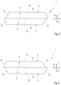
- a side view of the magnet assembly in another embodiment,
- Fig. 4
- a side view of the magnet assembly in a further embodiment,
- Fig. 5
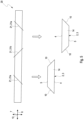
- a side view during the manufacture of the magnet assembly,
- Fig. 6
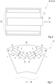
- a highly simplified sectional view of a rotor in an electrical machine,
- Fig. 7
- a sectional view of the rotor in the area of magnet arrangements,
- Fig. 8
- a highly simplified, circuit diagram-like representation of a motor vehicle with the electric machine,
- Fig. 9
- a side view during the manufacture of the magnet assembly in another exemplary embodiment.
- A
magnet arrangement 1, as exemplary shown inFigures 1 to 4 and6 , is used in arotor 31, which is exemplary shown inFigures 6 and 7 . Therotor 31 is used in an electric machine 30 exemplary shown inFigures 6 and 7 . The electric machine 30 may be used in amotor vehicle 100 exemplary shown inFigure 8 . - The
magnet arrangement 1 is hereinafter also referred to asarrangement 1 for short. Thearrangement 1 comprises 2permanent magnets permanent magnet 2 and a secondpermanent magnet 3. In particular, thearrangement 1 is composed of thepermanent magnets Figures 1 and 2 , for example, the following applies to the respectivepermanent magnet permanent magnet contact surface 4, wherein the contact surfaces 4 of thepermanent magnets permanent magnet outer surface 5 facing away from the associatedcontact surface 4. Thecontact surface 4 and theouter surface 5 extend in parallel in adirection 6, which will also be referred to hereinafter aslongitudinal direction 6. Moreover, thecontact surface 4 and theouter surface 5 are spaced apart from each other in adirection 7 extending transversely to thelongitudinal direction 6. Thedirection 7 is hereinafter also referred to as thevertical direction 7. As can be seen, for example, fromFigure 1 , theouter surface 5 and thecontact surface 4 each have alength longitudinal direction 6. Thelength 8 of theouter surface 5 is hereinafter also referred to as theouter length 8. Thelength 9 of thecontact surface 4 is also referred to hereinafter as thecontact length 9. Thecontact length 9 is greater than theouter length 8. That is, thecontact surface 4 is greater in thelongitudinal direction 6 than theouter surface 5. As can further be seen fromFigures 1 and 2 , thepermanent magnet surfaces 10 facing away from each other in thelongitudinal direction 6. Thesurfaces 10 are hereinafter also referred to as end faces 10. The respective end faces 10 connect thecontact surface 4 and theouter surface 5 to each other. At least one of the end faces 10 extends inwardly inclined relative to thelongitudinal direction 6, so that thepermanent magnet end face 10. This results in a trapezoidal shape in the side views shown inFigures 1 to 4 and6 , or in a section along thelongitudinal direction 6. Thus, a larger volume compared to a cuboid magnet results, so that therotor 31 with themagnet arrangement 1 has an improved electromagnetic performance. - As can be seen from
Figures 1 to 4 and6 , in the shown exemplary embodiments the contact surfaces 4 of thepermanent magnets magnet arrangement 1 are formed identically. In the shown exemplary embodiments, bothpermanent magnets magnet arrangement 1 are formed identically in shape and have corresponding polarities, so that themagnet arrangement 1 is polarized in the manner of a one-piece permanent magnet (not shown). - As can be seen from
Figures 1 and 2 as well as 6, it is conceivable that the contact surfaces 4 abut on each other and completely overlap. As can be seen fromFigures 3 and 4 , it is also possible that the contact surfaces 4 abut on each other and are offset from each other. In the exemplary embodiment ofFigures 3 and 4 , the contact surfaces 4 are offset from each other in thelongitudinal direction 6. - In the exemplary embodiments shown, both end faces 10 of the respective
permanent magnets magnet arrangement 1 are inclined inwardly, so that a trapezoidal shape is obtained in the region of both end faces 10. Moreover, in the exemplary embodiments shown, theouter surface 5 is arranged centrally with respect to thecontact surface 4 in thelongitudinal direction 6. Thus, a symmetrical configuration of thepermanent magnet symmetry plane 12 of the respectivepermanent magnet longitudinal direction 6 and running in thevertical direction 7. In the exemplary embodiment ofFigures 1 and 2 , thesymmetry plane 12 is also asymmetry plane 12 of themagnet arrangement 1. In this exemplary embodiment, themagnet arrangement 1 comprises afurther symmetry plane 11 extending between the contact surfaces 4 and parallel to the contact surfaces 4. In other words, themagnet arrangement 1 is symmetrical with respect to thesymmetry plane 11 of thearrangement 1 extending between the contact surfaces 4 and parallel to the contact surfaces 4. - The respective
permanent magnet longitudinal direction 6 and facing away from each other in atransverse direction 13 extending transversely to thelongitudinal direction 6 and transversely to thevertical direction 7. In the Figures shown due to the side views of therespective magnet arrangement 1, only one of the side surfaces 14 is visible. The side surfaces 14 of the respectivepermanent magnet contact surface 4 to theouter surface 5. In the exemplary embodiments shown, the side surfaces 14 extend parallel in thevertical direction 7. Thus, with the exception of the regions of the end faces 10, the respectivepermanent magnet - The
magnet arrangement 1 can be manufactured in a simplified manner as shown inFigures 5 and9 . For this purpose, at least one cuboid-shapedmagnet bar 20 is provided, which extends longitudinally inlongitudinal direction 6. As indicated by lines inFigures 5 and9 , cuts 21 are made in the at least onemagnet bar 20 at intervals from one another in thelongitudinal direction 6. More specifically alternating first cuts 21, 21a and second cuts 21, 21b are made in the at least onemagnet bar 20 spaced apart from each other in thelongitudinal direction 6. As can be seen fromFigures 5 and9 , the first cuts 21, 21a and second cuts 21, 21b are inclined relative to thelongitudinal direction 6 and run in opposite directions to each other. Consequently, apermanent magnet magnet arrangement 1 is manufactured by two spatially successive cuts 21 in thelongitudinal direction 6. The successive cuts 21 can be made subsequently or simultaneous. To produce amagnet arrangement 1, a firstpermanent magnet 2 and a secondpermanent magnet 3 are attached to each other with their contact surfaces 9. - In the exemplary embodiment shown in
Figure 5 , the cuts 21 are made in asingle magnet bar 20. AsFigure 5 shows, in this embodiment the successive cuts 21, by way of example, are placed symmetrically. As a result, al thepermanent magnets - In the exemplary embodiment shown in
Figure 9 , at least two cuboid-shaped magnet bars 20 are vertically arranged adjacent one another to form abar arrangement 22. The is, thebar arrangement 22 comprises at least twomagnet bars 20 adjacent one another to transverse to their longitudinal extension. The first cuts 21, 21a and second cuts 21, 21b are made in thebar arrangement 22 at intervals from one another in thelongitudinal direction 6 and thus successively, so that apermanent magnet magnet arrangement 1 is produced by the successive cuts 21 in therespective magnet bar 20. In this embodimentpermanent magnets Figure 9 , in this embodiment the successive cuts 21, by way of example, are placed symmetrically using identical magnet bars 20. As a result, different shapes ofpermanent magnets permeant magnets permanent magnets permeant magnets permeant magnets permeant magnets permanent magnets - Referring to
Figures 6 and 7 , therotor 31, in operation, rotates about an axial axis ofrotation 36. As shown only inFigure 7 , therotor 31 comprises alamination 35. Thelamination 35 is non-rotatably attached to therotor 31 and thus torque proof with therotor 31. As also shown inFigure 7 only, at least onesuch magnet arrangement 1 is non-rotatably attached to thelamination 35 and thus to therotor 3. In the exemplary embodiment shown, therotor 31 has at least twosuch magnet arrangements 1. Themagnet arrangements 1 are spaced apart from one another and, preferably evenly, surrounding the axis ofrotation 36. In the view shown inFigure 7 two of themagnet arrangements 1 can be seen in a V configuration. As can be seen fromFigure 7 , thelongitudinal directions 6 of themagnet arrangements 1 are inclined to each other and transverse or inclined to the axis ofrotation 36. In the exemplary embodiment shown inFigure 7 ,magnet arrangements 1 of the exemplary embodiment shown inFigure 1 are used by way of example. Of course, at least onemagnet arrangement 1 of the exemplary embodiment ofFigure 3 and/or of the exemplary embodiment ofFigure 4 can also be used. In therotor 31 of the exemplary embodiment shown, therespective magnet arrangement 1 is laminated into therotor 31 via the end faces 10 wherein the air pockets/magnet barriers are not shown for the clarity of the picture. - The electrical machine 30 with the
rotor 31 further comprises a stator 32. The stator 32 surrounds therotor 31 in the shown exemplary embodiment. In operation, the stator 32 interacts electromagnetically with therotor 31, in particular with the at least onemagnet arrangement 1. The interaction is such that therotor 31 rotates about the axis ofrotation 36. Advantageously, the electric machine 30 is an electric motor 33. The electric motor 33 may be used for propulsion, i.e. may be a traction motor 34. - According to
Figure 8 , the electric machine 30, in particular the electric motor 33, can be used in amotor vehicle 100. In this context, the electric motor 33 may serve to drive themotor vehicle 100, i.e. it may be a traction motor 34. To this end, as indicated inFigure 8 , the traction motor 34 drives at least onewheel 101 of themotor vehicle 100.
Claims (18)
- A magnet assembly (1) for a rotor (31) of an electric machine (30),- with a first permanent magnet (2) and a second permanent magnet (3),- wherein the respective permanent magnet (2, 3):• has a contact surface (4) and an outer surface (5) facing away from the contact surface (4), which surfaces (4, 5) extend parallel in a longitudinal direction (6) and are spaced apart from one another in a vertical direction (7) extending transversely to the longitudinal direction (6),• the outer surface (5) has an outer length (8) extending in the longitudinal direction (6) and the contact surface (4) has a contact length (9) extending in the longitudinal direction (6) which is greater than the outer length (8),• has two end faces (10) facing away from one another in the longitudinal direction (6), which in each case connect the contact face (4) and the outer face (5) to one another,• at least one of the end faces (10) is inclined inwardly relative to the longitudinal direction (6) so that the permanent magnet (2, 3) has a trapezoidal like shape in the region of the end face (10),- wherein the contact surfaces (4) of the permanent magnets (2, 3) abut on each other.
- Magnet arrangement according to claim 1,
characterized in that
the contact surfaces (4) of the permanent magnets (2, 3) are of the same design and in particular completely overlap. - Magnet arrangement according to claim 1 or 2,
characterized in that
the permanent magnets (2, 3) are of the same design. - Magnet arrangement according to one of the claims 1 to 3,
characterized in that
the magnet arrangement (1) is symmetrical with respect to a symmetry plane (11) of the arrangement (1) extending between the contact surfaces (4) and parallel to the contact surfaces (4). - Magnet arrangement according to any one of claims 1 to 4,
characterized in that
both end faces (10) of at least one of the permanent magnets (2, 3) are inclined inwardly relative to the longitudinal direction (6) so that both end faces (10) of the permanent magnet (2, 3) are trapezoidally shaped. - Magnet arrangement according to claim 5,
characterized in that
the outer surface (5) is arranged centrally in the longitudinal direction (6) relative to the contact surface (5), so that the permanent magnet (2, 3) is formed symmetrically with respect to a symmetry plane (12) of the permanent magnet running centrally through the contact surface (4) and in the vertical direction (7). - Magnet arrangement according to one of claims 1 to 6,
characterized in that
at least one of the permanent magnets (2, 3) has two side faces (14) which run in the longitudinal direction (6) and face away from one another in a transverse direction (13) running transversely with respect to the longitudinal direction (6) and transversely with respect to the vertical direction (7), which side faces (14) connect the contact face (4) to the outer face (5) and extend parallel in the vertical direction (7). - Magnet arrangement according to one of claims 1 to 7,
characterized in that
the contact surfaces (6) abut on each other and completely overlap. - Magnet arrangement according to one of claims 1 to 7,
characterized in that
the contact surfaces (6) abut on each other and are offset from each other. - A method of manufacturing a magnet assembly (1) according to any one of claims 1 to 9,- wherein at least one cuboid-shaped magnet bar (20) is provided which extends longitudinally in longitudinal direction (6),- wherein alternating first cuts (21, 21a) and second cuts (21, 21b), which are inclined relative to the longitudinal direction (6) and directed in opposite directions to one another, are made in the at least one magnet bar (10) at intervals from one another in the longitudinal direction (6), so that a permanent magnet (2, 3) of the magnet arrangement (1) is produced by successive cuts (21) in the respective magnet bar (20),- wherein a first permanent magnet (2) and a second permanent magnet (3) are attached to each other with their contact surfaces (9) and thus the magnet arrangement (1) is produced.
- Method according to claim 10,
characterized in that- at least two cuboid-shaped magnet bars (20) are arranged adjacent one vertically to form a bar arrangement (22),- the alternating first cuts (21, 21a) and second cuts (21, 21b) are made in the bar arrangement at intervals from one another in the longitudinal direction (6), so that a permanent magnet (2, 3) of the magnet arrangement (1) is produced by successive cuts (21) in the respective magnet bar (20). - Rotor (31) for an electric machine (30),- with a lamination (35) which rotates in operation about an axial axis of rotation (36),- with at least one magnet arrangement (1) according to any one of claims 1 to 9, which is attached to the lamination (35) in a rotationally fixed manner.
- Rotor according to claim 12,
characterized in that
the longitudinal direction (6) extends transversely or inclined to the axis of rotation (36). - Rotor according to claim 12 or 13,
characterized in that
at least two such magnet arrangements (1) are mounted on the rotor (31), which magnet arrangements (1) are spaced apart from each other surrounding the axis of rotation (36). - Rotor according to any one of claims 12 to 14,
characterized in that
at least one of the at least one magnet arrangements (1) is laminated in the rotor (31) via the end faces (10). - An electric machine (30), in particular an electric motor (33), comprising a rotor (31) according to any one of claims 12 to 15 and a stator (32) which electromagnetically cooperates with the rotor (31) during operation.
- An electric machine according to claim 16,
characterized in that
the electric machine (30) is configured as a traction motor (34). - Motor vehicle (100) comprising an electric machine (30) according to claim 16 or 17.
Priority Applications (2)
| Application Number | Priority Date | Filing Date | Title |
|---|---|---|---|
| EP23167566.1A EP4447274A1 (en) | 2023-04-12 | 2023-04-12 | Magnet arrangement for a rotor of an electric machine |
| PCT/EP2024/058846 WO2024213425A1 (en) | 2023-04-12 | 2024-04-02 | Magnet arrangement for a rotor of an electric machine |
Applications Claiming Priority (1)
| Application Number | Priority Date | Filing Date | Title |
|---|---|---|---|
| EP23167566.1A EP4447274A1 (en) | 2023-04-12 | 2023-04-12 | Magnet arrangement for a rotor of an electric machine |
Publications (1)
| Publication Number | Publication Date |
|---|---|
| EP4447274A1 true EP4447274A1 (en) | 2024-10-16 |
Family
ID=86006748
Family Applications (1)
| Application Number | Title | Priority Date | Filing Date |
|---|---|---|---|
| EP23167566.1A Pending EP4447274A1 (en) | 2023-04-12 | 2023-04-12 | Magnet arrangement for a rotor of an electric machine |
Country Status (2)
| Country | Link |
|---|---|
| EP (1) | EP4447274A1 (en) |
| WO (1) | WO2024213425A1 (en) |
Citations (6)
| Publication number | Priority date | Publication date | Assignee | Title |
|---|---|---|---|---|
| US5184395A (en) * | 1989-07-03 | 1993-02-09 | Comec S.R.L. | System for manufacturing permanent magnetic field generators and relevant magnet geometries therefor |
| EP2348613A1 (en) | 2008-11-19 | 2011-07-27 | Mitsubishi Electric Corporation | Rotor of motor and motor and fan and compressor |
| EP2466727A1 (en) * | 2009-08-12 | 2012-06-20 | Hitachi Automotive Systems, Ltd. | Dynamo-electric machine for use in vehicles |
| US20150001980A1 (en) * | 2012-03-13 | 2015-01-01 | Brose Fahrzeugteile Gmbh & Co. Kg, Wuerzburg | Efficient electric machine |
| US20180145552A1 (en) | 2016-11-15 | 2018-05-24 | Toyota Jidosha Kabushiki Kaisha | Rotary electric machine |
| US20200228038A1 (en) * | 2017-08-01 | 2020-07-16 | Denso Corporation | Rotary electric machine, rotary electric machine drive system, magnet, method of manufacturing magnet, magnetizing apparatus, and magnet unit |
-
2023
- 2023-04-12 EP EP23167566.1A patent/EP4447274A1/en active Pending
-
2024
- 2024-04-02 WO PCT/EP2024/058846 patent/WO2024213425A1/en not_active Ceased
Patent Citations (6)
| Publication number | Priority date | Publication date | Assignee | Title |
|---|---|---|---|---|
| US5184395A (en) * | 1989-07-03 | 1993-02-09 | Comec S.R.L. | System for manufacturing permanent magnetic field generators and relevant magnet geometries therefor |
| EP2348613A1 (en) | 2008-11-19 | 2011-07-27 | Mitsubishi Electric Corporation | Rotor of motor and motor and fan and compressor |
| EP2466727A1 (en) * | 2009-08-12 | 2012-06-20 | Hitachi Automotive Systems, Ltd. | Dynamo-electric machine for use in vehicles |
| US20150001980A1 (en) * | 2012-03-13 | 2015-01-01 | Brose Fahrzeugteile Gmbh & Co. Kg, Wuerzburg | Efficient electric machine |
| US20180145552A1 (en) | 2016-11-15 | 2018-05-24 | Toyota Jidosha Kabushiki Kaisha | Rotary electric machine |
| US20200228038A1 (en) * | 2017-08-01 | 2020-07-16 | Denso Corporation | Rotary electric machine, rotary electric machine drive system, magnet, method of manufacturing magnet, magnetizing apparatus, and magnet unit |
Also Published As
| Publication number | Publication date |
|---|---|
| WO2024213425A1 (en) | 2024-10-17 |
Similar Documents
| Publication | Publication Date | Title |
|---|---|---|
| US7504754B2 (en) | Rotor having multiple permanent-magnet pieces in a cavity | |
| CN101272066B (en) | Rotor and rotating electrical machine for permanent magnet type synchronous rotating electrical machine | |
| CN100342619C (en) | Its rotor is suitable for high-speed rotating motors | |
| CN103166408B (en) | Multi-layer arc-shaped permanent magnet machine with reduced rotational stress | |
| US20050140236A1 (en) | Rotor structure of multi-layer interior permanent magnet motor | |
| US20220209600A1 (en) | Rotor of rotary electric machine | |
| US8760026B2 (en) | Rotor with V-shaped permanent magnet arrangement, rotating electric machine, vehicle, elevator, fluid machine, and processing machine | |
| JP7314789B2 (en) | Embedded magnet rotor and rotating electric machine | |
| JP4195788B2 (en) | Synchronous rotating electrical machine with external rotor | |
| CN207968110U (en) | The rotor pack and rotor of motor for permanent-magnet-field | |
| CN103117604A (en) | Electric rotating machine | |
| JP2013162677A (en) | Axial gap type rotary electric machine and wheel | |
| US10651697B2 (en) | Magnet for IPM rotor, IPM rotor, and method of manufacturing magnet for IPM rotor | |
| US6803690B2 (en) | Electric motor excited by permanent magnets | |
| WO2018037529A1 (en) | Rotary electric machine | |
| US20220060070A1 (en) | Rotating electric machine | |
| JP4113353B2 (en) | Rotating electric machine | |
| CN101517863A (en) | Axial-flux electric machine | |
| JP2022150091A (en) | Rotor, rotary electric machine, driving device, and moving body | |
| WO2024213425A1 (en) | Magnet arrangement for a rotor of an electric machine | |
| US9559554B2 (en) | Split rotor stack gap with a corner air barrier | |
| US12334778B2 (en) | Rotor for a permanently energized electrical machine, with a support structure | |
| CN120127852A (en) | Stator and motor for electric motor | |
| WO2020230594A1 (en) | Rotating electric machine and method of manufacturing core | |
| US12580435B2 (en) | Selective permeability rotor sleeve for interior permanent magnet machine |
Legal Events
| Date | Code | Title | Description |
|---|---|---|---|
| PUAI | Public reference made under article 153(3) epc to a published international application that has entered the european phase |
Free format text: ORIGINAL CODE: 0009012 |
|
| STAA | Information on the status of an ep patent application or granted ep patent |
Free format text: STATUS: THE APPLICATION HAS BEEN PUBLISHED |
|
| AK | Designated contracting states |
Kind code of ref document: A1 Designated state(s): AL AT BE BG CH CY CZ DE DK EE ES FI FR GB GR HR HU IE IS IT LI LT LU LV MC ME MK MT NL NO PL PT RO RS SE SI SK SM TR |
|
| STAA | Information on the status of an ep patent application or granted ep patent |
Free format text: STATUS: REQUEST FOR EXAMINATION WAS MADE |
|
| 17P | Request for examination filed |
Effective date: 20250306 |