EP2466727A1 - Dynamo-electric machine for use in vehicles - Google Patents
Dynamo-electric machine for use in vehicles Download PDFInfo
- Publication number
- EP2466727A1 EP2466727A1 EP10808252A EP10808252A EP2466727A1 EP 2466727 A1 EP2466727 A1 EP 2466727A1 EP 10808252 A EP10808252 A EP 10808252A EP 10808252 A EP10808252 A EP 10808252A EP 2466727 A1 EP2466727 A1 EP 2466727A1
- Authority
- EP
- European Patent Office
- Prior art keywords
- along
- rotor
- magnet
- electric machine
- rotating electric
- Prior art date
- Legal status (The legal status is an assumption and is not a legal conclusion. Google has not performed a legal analysis and makes no representation as to the accuracy of the status listed.)
- Granted
Links
- 238000003780 insertion Methods 0.000 claims abstract description 106
- 230000037431 insertion Effects 0.000 claims abstract description 106
- 238000004804 winding Methods 0.000 claims abstract description 49
- 229910000831 Steel Inorganic materials 0.000 claims abstract description 29
- 239000010959 steel Substances 0.000 claims abstract description 29
- 238000010030 laminating Methods 0.000 claims abstract description 12
- 230000010349 pulsation Effects 0.000 description 120
- 239000011162 core material Substances 0.000 description 69
- 230000004907 flux Effects 0.000 description 56
- 230000015572 biosynthetic process Effects 0.000 description 36
- 238000005755 formation reaction Methods 0.000 description 36
- 230000010287 polarization Effects 0.000 description 27
- 230000001603 reducing effect Effects 0.000 description 25
- 230000008901 benefit Effects 0.000 description 22
- 238000006243 chemical reaction Methods 0.000 description 18
- 230000009467 reduction Effects 0.000 description 17
- 238000004519 manufacturing process Methods 0.000 description 14
- 238000001816 cooling Methods 0.000 description 11
- 230000002411 adverse Effects 0.000 description 8
- 238000000034 method Methods 0.000 description 8
- 230000008569 process Effects 0.000 description 8
- 238000013461 design Methods 0.000 description 6
- 238000010586 diagram Methods 0.000 description 6
- 239000003921 oil Substances 0.000 description 6
- XEEYBQQBJWHFJM-UHFFFAOYSA-N Iron Chemical compound [Fe] XEEYBQQBJWHFJM-UHFFFAOYSA-N 0.000 description 5
- 230000000694 effects Effects 0.000 description 5
- 229920006395 saturated elastomer Polymers 0.000 description 5
- 239000004065 semiconductor Substances 0.000 description 5
- 229910052779 Neodymium Inorganic materials 0.000 description 4
- 230000005540 biological transmission Effects 0.000 description 4
- 238000004891 communication Methods 0.000 description 4
- 230000001010 compromised effect Effects 0.000 description 4
- 230000009347 mechanical transmission Effects 0.000 description 4
- QEFYFXOXNSNQGX-UHFFFAOYSA-N neodymium atom Chemical compound [Nd] QEFYFXOXNSNQGX-UHFFFAOYSA-N 0.000 description 4
- 229910001172 neodymium magnet Inorganic materials 0.000 description 4
- 229910000976 Electrical steel Inorganic materials 0.000 description 3
- 229910052772 Samarium Inorganic materials 0.000 description 3
- 230000001154 acute effect Effects 0.000 description 3
- 230000005415 magnetization Effects 0.000 description 3
- KZUNJOHGWZRPMI-UHFFFAOYSA-N samarium atom Chemical compound [Sm] KZUNJOHGWZRPMI-UHFFFAOYSA-N 0.000 description 3
- 229910017052 cobalt Inorganic materials 0.000 description 2
- 239000010941 cobalt Substances 0.000 description 2
- GUTLYIVDDKVIGB-UHFFFAOYSA-N cobalt atom Chemical compound [Co] GUTLYIVDDKVIGB-UHFFFAOYSA-N 0.000 description 2
- 239000000470 constituent Substances 0.000 description 2
- 238000001514 detection method Methods 0.000 description 2
- 238000009826 distribution Methods 0.000 description 2
- 238000005516 engineering process Methods 0.000 description 2
- 230000006872 improvement Effects 0.000 description 2
- 229910052742 iron Inorganic materials 0.000 description 2
- 230000001172 regenerating effect Effects 0.000 description 2
- 239000011347 resin Substances 0.000 description 2
- 229920005989 resin Polymers 0.000 description 2
- ZOXJGFHDIHLPTG-UHFFFAOYSA-N Boron Chemical compound [B] ZOXJGFHDIHLPTG-UHFFFAOYSA-N 0.000 description 1
- HBBGRARXTFLTSG-UHFFFAOYSA-N Lithium ion Chemical compound [Li+] HBBGRARXTFLTSG-UHFFFAOYSA-N 0.000 description 1
- 239000000853 adhesive Substances 0.000 description 1
- 230000001070 adhesive effect Effects 0.000 description 1
- 229910052796 boron Inorganic materials 0.000 description 1
- 239000003990 capacitor Substances 0.000 description 1
- 230000008859 change Effects 0.000 description 1
- 239000004020 conductor Substances 0.000 description 1
- 238000011161 development Methods 0.000 description 1
- 239000012530 fluid Substances 0.000 description 1
- 238000001746 injection moulding Methods 0.000 description 1
- 238000011900 installation process Methods 0.000 description 1
- 238000009413 insulation Methods 0.000 description 1
- 239000012212 insulator Substances 0.000 description 1
- 230000010354 integration Effects 0.000 description 1
- 229910001416 lithium ion Inorganic materials 0.000 description 1
- 238000003754 machining Methods 0.000 description 1
- 239000000696 magnetic material Substances 0.000 description 1
- 239000006247 magnetic powder Substances 0.000 description 1
- 239000000843 powder Substances 0.000 description 1
- 238000010248 power generation Methods 0.000 description 1
- 230000000644 propagated effect Effects 0.000 description 1
- 229910052761 rare earth metal Inorganic materials 0.000 description 1
- 150000002910 rare earth metals Chemical class 0.000 description 1
- 239000000243 solution Substances 0.000 description 1
- 239000000758 substrate Substances 0.000 description 1
- 229910000859 α-Fe Inorganic materials 0.000 description 1
Images


Classifications
-
- H—ELECTRICITY
- H02—GENERATION; CONVERSION OR DISTRIBUTION OF ELECTRIC POWER
- H02K—DYNAMO-ELECTRIC MACHINES
- H02K1/00—Details of the magnetic circuit
- H02K1/06—Details of the magnetic circuit characterised by the shape, form or construction
- H02K1/22—Rotating parts of the magnetic circuit
- H02K1/27—Rotor cores with permanent magnets
- H02K1/2706—Inner rotors
- H02K1/272—Inner rotors the magnetisation axis of the magnets being perpendicular to the rotor axis
- H02K1/274—Inner rotors the magnetisation axis of the magnets being perpendicular to the rotor axis the rotor consisting of two or more circumferentially positioned magnets
- H02K1/2753—Inner rotors the magnetisation axis of the magnets being perpendicular to the rotor axis the rotor consisting of two or more circumferentially positioned magnets the rotor consisting of magnets or groups of magnets arranged with alternating polarity
- H02K1/276—Magnets embedded in the magnetic core, e.g. interior permanent magnets [IPM]
-
- B—PERFORMING OPERATIONS; TRANSPORTING
- B60—VEHICLES IN GENERAL
- B60L—PROPULSION OF ELECTRICALLY-PROPELLED VEHICLES; SUPPLYING ELECTRIC POWER FOR AUXILIARY EQUIPMENT OF ELECTRICALLY-PROPELLED VEHICLES; ELECTRODYNAMIC BRAKE SYSTEMS FOR VEHICLES IN GENERAL; MAGNETIC SUSPENSION OR LEVITATION FOR VEHICLES; MONITORING OPERATING VARIABLES OF ELECTRICALLY-PROPELLED VEHICLES; ELECTRIC SAFETY DEVICES FOR ELECTRICALLY-PROPELLED VEHICLES
- B60L1/00—Supplying electric power to auxiliary equipment of vehicles
- B60L1/02—Supplying electric power to auxiliary equipment of vehicles to electric heating circuits
-
- B—PERFORMING OPERATIONS; TRANSPORTING
- B60—VEHICLES IN GENERAL
- B60L—PROPULSION OF ELECTRICALLY-PROPELLED VEHICLES; SUPPLYING ELECTRIC POWER FOR AUXILIARY EQUIPMENT OF ELECTRICALLY-PROPELLED VEHICLES; ELECTRODYNAMIC BRAKE SYSTEMS FOR VEHICLES IN GENERAL; MAGNETIC SUSPENSION OR LEVITATION FOR VEHICLES; MONITORING OPERATING VARIABLES OF ELECTRICALLY-PROPELLED VEHICLES; ELECTRIC SAFETY DEVICES FOR ELECTRICALLY-PROPELLED VEHICLES
- B60L15/00—Methods, circuits, or devices for controlling the traction-motor speed of electrically-propelled vehicles
- B60L15/007—Physical arrangements or structures of drive train converters specially adapted for the propulsion motors of electric vehicles
-
- B—PERFORMING OPERATIONS; TRANSPORTING
- B60—VEHICLES IN GENERAL
- B60L—PROPULSION OF ELECTRICALLY-PROPELLED VEHICLES; SUPPLYING ELECTRIC POWER FOR AUXILIARY EQUIPMENT OF ELECTRICALLY-PROPELLED VEHICLES; ELECTRODYNAMIC BRAKE SYSTEMS FOR VEHICLES IN GENERAL; MAGNETIC SUSPENSION OR LEVITATION FOR VEHICLES; MONITORING OPERATING VARIABLES OF ELECTRICALLY-PROPELLED VEHICLES; ELECTRIC SAFETY DEVICES FOR ELECTRICALLY-PROPELLED VEHICLES
- B60L15/00—Methods, circuits, or devices for controlling the traction-motor speed of electrically-propelled vehicles
- B60L15/20—Methods, circuits, or devices for controlling the traction-motor speed of electrically-propelled vehicles for control of the vehicle or its driving motor to achieve a desired performance, e.g. speed, torque, programmed variation of speed
- B60L15/2009—Methods, circuits, or devices for controlling the traction-motor speed of electrically-propelled vehicles for control of the vehicle or its driving motor to achieve a desired performance, e.g. speed, torque, programmed variation of speed for braking
-
- B—PERFORMING OPERATIONS; TRANSPORTING
- B60—VEHICLES IN GENERAL
- B60L—PROPULSION OF ELECTRICALLY-PROPELLED VEHICLES; SUPPLYING ELECTRIC POWER FOR AUXILIARY EQUIPMENT OF ELECTRICALLY-PROPELLED VEHICLES; ELECTRODYNAMIC BRAKE SYSTEMS FOR VEHICLES IN GENERAL; MAGNETIC SUSPENSION OR LEVITATION FOR VEHICLES; MONITORING OPERATING VARIABLES OF ELECTRICALLY-PROPELLED VEHICLES; ELECTRIC SAFETY DEVICES FOR ELECTRICALLY-PROPELLED VEHICLES
- B60L3/00—Electric devices on electrically-propelled vehicles for safety purposes; Monitoring operating variables, e.g. speed, deceleration or energy consumption
- B60L3/0023—Detecting, eliminating, remedying or compensating for drive train abnormalities, e.g. failures within the drive train
- B60L3/0061—Detecting, eliminating, remedying or compensating for drive train abnormalities, e.g. failures within the drive train relating to electrical machines
-
- B—PERFORMING OPERATIONS; TRANSPORTING
- B60—VEHICLES IN GENERAL
- B60L—PROPULSION OF ELECTRICALLY-PROPELLED VEHICLES; SUPPLYING ELECTRIC POWER FOR AUXILIARY EQUIPMENT OF ELECTRICALLY-PROPELLED VEHICLES; ELECTRODYNAMIC BRAKE SYSTEMS FOR VEHICLES IN GENERAL; MAGNETIC SUSPENSION OR LEVITATION FOR VEHICLES; MONITORING OPERATING VARIABLES OF ELECTRICALLY-PROPELLED VEHICLES; ELECTRIC SAFETY DEVICES FOR ELECTRICALLY-PROPELLED VEHICLES
- B60L50/00—Electric propulsion with power supplied within the vehicle
- B60L50/10—Electric propulsion with power supplied within the vehicle using propulsion power supplied by engine-driven generators, e.g. generators driven by combustion engines
- B60L50/16—Electric propulsion with power supplied within the vehicle using propulsion power supplied by engine-driven generators, e.g. generators driven by combustion engines with provision for separate direct mechanical propulsion
-
- B—PERFORMING OPERATIONS; TRANSPORTING
- B60—VEHICLES IN GENERAL
- B60L—PROPULSION OF ELECTRICALLY-PROPELLED VEHICLES; SUPPLYING ELECTRIC POWER FOR AUXILIARY EQUIPMENT OF ELECTRICALLY-PROPELLED VEHICLES; ELECTRODYNAMIC BRAKE SYSTEMS FOR VEHICLES IN GENERAL; MAGNETIC SUSPENSION OR LEVITATION FOR VEHICLES; MONITORING OPERATING VARIABLES OF ELECTRICALLY-PROPELLED VEHICLES; ELECTRIC SAFETY DEVICES FOR ELECTRICALLY-PROPELLED VEHICLES
- B60L50/00—Electric propulsion with power supplied within the vehicle
- B60L50/50—Electric propulsion with power supplied within the vehicle using propulsion power supplied by batteries or fuel cells
- B60L50/60—Electric propulsion with power supplied within the vehicle using propulsion power supplied by batteries or fuel cells using power supplied by batteries
- B60L50/61—Electric propulsion with power supplied within the vehicle using propulsion power supplied by batteries or fuel cells using power supplied by batteries by batteries charged by engine-driven generators, e.g. series hybrid electric vehicles
-
- B—PERFORMING OPERATIONS; TRANSPORTING
- B60—VEHICLES IN GENERAL
- B60L—PROPULSION OF ELECTRICALLY-PROPELLED VEHICLES; SUPPLYING ELECTRIC POWER FOR AUXILIARY EQUIPMENT OF ELECTRICALLY-PROPELLED VEHICLES; ELECTRODYNAMIC BRAKE SYSTEMS FOR VEHICLES IN GENERAL; MAGNETIC SUSPENSION OR LEVITATION FOR VEHICLES; MONITORING OPERATING VARIABLES OF ELECTRICALLY-PROPELLED VEHICLES; ELECTRIC SAFETY DEVICES FOR ELECTRICALLY-PROPELLED VEHICLES
- B60L7/00—Electrodynamic brake systems for vehicles in general
- B60L7/10—Dynamic electric regenerative braking
- B60L7/14—Dynamic electric regenerative braking for vehicles propelled by AC motors
-
- B—PERFORMING OPERATIONS; TRANSPORTING
- B60—VEHICLES IN GENERAL
- B60L—PROPULSION OF ELECTRICALLY-PROPELLED VEHICLES; SUPPLYING ELECTRIC POWER FOR AUXILIARY EQUIPMENT OF ELECTRICALLY-PROPELLED VEHICLES; ELECTRODYNAMIC BRAKE SYSTEMS FOR VEHICLES IN GENERAL; MAGNETIC SUSPENSION OR LEVITATION FOR VEHICLES; MONITORING OPERATING VARIABLES OF ELECTRICALLY-PROPELLED VEHICLES; ELECTRIC SAFETY DEVICES FOR ELECTRICALLY-PROPELLED VEHICLES
- B60L7/00—Electrodynamic brake systems for vehicles in general
- B60L7/10—Dynamic electric regenerative braking
- B60L7/18—Controlling the braking effect
-
- B—PERFORMING OPERATIONS; TRANSPORTING
- B60—VEHICLES IN GENERAL
- B60L—PROPULSION OF ELECTRICALLY-PROPELLED VEHICLES; SUPPLYING ELECTRIC POWER FOR AUXILIARY EQUIPMENT OF ELECTRICALLY-PROPELLED VEHICLES; ELECTRODYNAMIC BRAKE SYSTEMS FOR VEHICLES IN GENERAL; MAGNETIC SUSPENSION OR LEVITATION FOR VEHICLES; MONITORING OPERATING VARIABLES OF ELECTRICALLY-PROPELLED VEHICLES; ELECTRIC SAFETY DEVICES FOR ELECTRICALLY-PROPELLED VEHICLES
- B60L2210/00—Converter types
- B60L2210/40—DC to AC converters
-
- B—PERFORMING OPERATIONS; TRANSPORTING
- B60—VEHICLES IN GENERAL
- B60L—PROPULSION OF ELECTRICALLY-PROPELLED VEHICLES; SUPPLYING ELECTRIC POWER FOR AUXILIARY EQUIPMENT OF ELECTRICALLY-PROPELLED VEHICLES; ELECTRODYNAMIC BRAKE SYSTEMS FOR VEHICLES IN GENERAL; MAGNETIC SUSPENSION OR LEVITATION FOR VEHICLES; MONITORING OPERATING VARIABLES OF ELECTRICALLY-PROPELLED VEHICLES; ELECTRIC SAFETY DEVICES FOR ELECTRICALLY-PROPELLED VEHICLES
- B60L2240/00—Control parameters of input or output; Target parameters
- B60L2240/10—Vehicle control parameters
- B60L2240/12—Speed
-
- B—PERFORMING OPERATIONS; TRANSPORTING
- B60—VEHICLES IN GENERAL
- B60L—PROPULSION OF ELECTRICALLY-PROPELLED VEHICLES; SUPPLYING ELECTRIC POWER FOR AUXILIARY EQUIPMENT OF ELECTRICALLY-PROPELLED VEHICLES; ELECTRODYNAMIC BRAKE SYSTEMS FOR VEHICLES IN GENERAL; MAGNETIC SUSPENSION OR LEVITATION FOR VEHICLES; MONITORING OPERATING VARIABLES OF ELECTRICALLY-PROPELLED VEHICLES; ELECTRIC SAFETY DEVICES FOR ELECTRICALLY-PROPELLED VEHICLES
- B60L2240/00—Control parameters of input or output; Target parameters
- B60L2240/10—Vehicle control parameters
- B60L2240/36—Temperature of vehicle components or parts
-
- B—PERFORMING OPERATIONS; TRANSPORTING
- B60—VEHICLES IN GENERAL
- B60L—PROPULSION OF ELECTRICALLY-PROPELLED VEHICLES; SUPPLYING ELECTRIC POWER FOR AUXILIARY EQUIPMENT OF ELECTRICALLY-PROPELLED VEHICLES; ELECTRODYNAMIC BRAKE SYSTEMS FOR VEHICLES IN GENERAL; MAGNETIC SUSPENSION OR LEVITATION FOR VEHICLES; MONITORING OPERATING VARIABLES OF ELECTRICALLY-PROPELLED VEHICLES; ELECTRIC SAFETY DEVICES FOR ELECTRICALLY-PROPELLED VEHICLES
- B60L2240/00—Control parameters of input or output; Target parameters
- B60L2240/40—Drive Train control parameters
- B60L2240/42—Drive Train control parameters related to electric machines
- B60L2240/421—Speed
-
- B—PERFORMING OPERATIONS; TRANSPORTING
- B60—VEHICLES IN GENERAL
- B60L—PROPULSION OF ELECTRICALLY-PROPELLED VEHICLES; SUPPLYING ELECTRIC POWER FOR AUXILIARY EQUIPMENT OF ELECTRICALLY-PROPELLED VEHICLES; ELECTRODYNAMIC BRAKE SYSTEMS FOR VEHICLES IN GENERAL; MAGNETIC SUSPENSION OR LEVITATION FOR VEHICLES; MONITORING OPERATING VARIABLES OF ELECTRICALLY-PROPELLED VEHICLES; ELECTRIC SAFETY DEVICES FOR ELECTRICALLY-PROPELLED VEHICLES
- B60L2240/00—Control parameters of input or output; Target parameters
- B60L2240/40—Drive Train control parameters
- B60L2240/42—Drive Train control parameters related to electric machines
- B60L2240/423—Torque
-
- B—PERFORMING OPERATIONS; TRANSPORTING
- B60—VEHICLES IN GENERAL
- B60L—PROPULSION OF ELECTRICALLY-PROPELLED VEHICLES; SUPPLYING ELECTRIC POWER FOR AUXILIARY EQUIPMENT OF ELECTRICALLY-PROPELLED VEHICLES; ELECTRODYNAMIC BRAKE SYSTEMS FOR VEHICLES IN GENERAL; MAGNETIC SUSPENSION OR LEVITATION FOR VEHICLES; MONITORING OPERATING VARIABLES OF ELECTRICALLY-PROPELLED VEHICLES; ELECTRIC SAFETY DEVICES FOR ELECTRICALLY-PROPELLED VEHICLES
- B60L2270/00—Problem solutions or means not otherwise provided for
- B60L2270/10—Emission reduction
- B60L2270/14—Emission reduction of noise
- B60L2270/145—Structure borne vibrations
-
- H—ELECTRICITY
- H02—GENERATION; CONVERSION OR DISTRIBUTION OF ELECTRIC POWER
- H02K—DYNAMO-ELECTRIC MACHINES
- H02K2201/00—Specific aspects not provided for in the other groups of this subclass relating to the magnetic circuits
- H02K2201/06—Magnetic cores, or permanent magnets characterised by their skew
-
- H—ELECTRICITY
- H02—GENERATION; CONVERSION OR DISTRIBUTION OF ELECTRIC POWER
- H02K—DYNAMO-ELECTRIC MACHINES
- H02K29/00—Motors or generators having non-mechanical commutating devices, e.g. discharge tubes or semiconductor devices
- H02K29/03—Motors or generators having non-mechanical commutating devices, e.g. discharge tubes or semiconductor devices with a magnetic circuit specially adapted for avoiding torque ripples or self-starting problems
-
- H—ELECTRICITY
- H02—GENERATION; CONVERSION OR DISTRIBUTION OF ELECTRIC POWER
- H02K—DYNAMO-ELECTRIC MACHINES
- H02K7/00—Arrangements for handling mechanical energy structurally associated with dynamo-electric machines, e.g. structural association with mechanical driving motors or auxiliary dynamo-electric machines
- H02K7/006—Structural association of a motor or generator with the drive train of a motor vehicle
-
- Y—GENERAL TAGGING OF NEW TECHNOLOGICAL DEVELOPMENTS; GENERAL TAGGING OF CROSS-SECTIONAL TECHNOLOGIES SPANNING OVER SEVERAL SECTIONS OF THE IPC; TECHNICAL SUBJECTS COVERED BY FORMER USPC CROSS-REFERENCE ART COLLECTIONS [XRACs] AND DIGESTS
- Y02—TECHNOLOGIES OR APPLICATIONS FOR MITIGATION OR ADAPTATION AGAINST CLIMATE CHANGE
- Y02T—CLIMATE CHANGE MITIGATION TECHNOLOGIES RELATED TO TRANSPORTATION
- Y02T10/00—Road transport of goods or passengers
- Y02T10/60—Other road transportation technologies with climate change mitigation effect
- Y02T10/62—Hybrid vehicles
-
- Y—GENERAL TAGGING OF NEW TECHNOLOGICAL DEVELOPMENTS; GENERAL TAGGING OF CROSS-SECTIONAL TECHNOLOGIES SPANNING OVER SEVERAL SECTIONS OF THE IPC; TECHNICAL SUBJECTS COVERED BY FORMER USPC CROSS-REFERENCE ART COLLECTIONS [XRACs] AND DIGESTS
- Y02—TECHNOLOGIES OR APPLICATIONS FOR MITIGATION OR ADAPTATION AGAINST CLIMATE CHANGE
- Y02T—CLIMATE CHANGE MITIGATION TECHNOLOGIES RELATED TO TRANSPORTATION
- Y02T10/00—Road transport of goods or passengers
- Y02T10/60—Other road transportation technologies with climate change mitigation effect
- Y02T10/64—Electric machine technologies in electromobility
-
- Y—GENERAL TAGGING OF NEW TECHNOLOGICAL DEVELOPMENTS; GENERAL TAGGING OF CROSS-SECTIONAL TECHNOLOGIES SPANNING OVER SEVERAL SECTIONS OF THE IPC; TECHNICAL SUBJECTS COVERED BY FORMER USPC CROSS-REFERENCE ART COLLECTIONS [XRACs] AND DIGESTS
- Y02—TECHNOLOGIES OR APPLICATIONS FOR MITIGATION OR ADAPTATION AGAINST CLIMATE CHANGE
- Y02T—CLIMATE CHANGE MITIGATION TECHNOLOGIES RELATED TO TRANSPORTATION
- Y02T10/00—Road transport of goods or passengers
- Y02T10/60—Other road transportation technologies with climate change mitigation effect
- Y02T10/70—Energy storage systems for electromobility, e.g. batteries
-
- Y—GENERAL TAGGING OF NEW TECHNOLOGICAL DEVELOPMENTS; GENERAL TAGGING OF CROSS-SECTIONAL TECHNOLOGIES SPANNING OVER SEVERAL SECTIONS OF THE IPC; TECHNICAL SUBJECTS COVERED BY FORMER USPC CROSS-REFERENCE ART COLLECTIONS [XRACs] AND DIGESTS
- Y02—TECHNOLOGIES OR APPLICATIONS FOR MITIGATION OR ADAPTATION AGAINST CLIMATE CHANGE
- Y02T—CLIMATE CHANGE MITIGATION TECHNOLOGIES RELATED TO TRANSPORTATION
- Y02T10/00—Road transport of goods or passengers
- Y02T10/60—Other road transportation technologies with climate change mitigation effect
- Y02T10/7072—Electromobility specific charging systems or methods for batteries, ultracapacitors, supercapacitors or double-layer capacitors
-
- Y—GENERAL TAGGING OF NEW TECHNOLOGICAL DEVELOPMENTS; GENERAL TAGGING OF CROSS-SECTIONAL TECHNOLOGIES SPANNING OVER SEVERAL SECTIONS OF THE IPC; TECHNICAL SUBJECTS COVERED BY FORMER USPC CROSS-REFERENCE ART COLLECTIONS [XRACs] AND DIGESTS
- Y02—TECHNOLOGIES OR APPLICATIONS FOR MITIGATION OR ADAPTATION AGAINST CLIMATE CHANGE
- Y02T—CLIMATE CHANGE MITIGATION TECHNOLOGIES RELATED TO TRANSPORTATION
- Y02T10/00—Road transport of goods or passengers
- Y02T10/60—Other road transportation technologies with climate change mitigation effect
- Y02T10/72—Electric energy management in electromobility
Definitions
- the present invention relates to a rotating electric machine for vehiclular use.
- the rotating electric machine installed in an electric vehicle to enable traveling operation includes permanent magnets constituted with sintered rare-earth magnets having strong magnetic energy.
- the permanent magnets are embedded within a rotor core.
- Torque pulsations induced by a cogging torque or the like, are bound to occur in a rotating electric machine. Such torque pulsations occurring in the rotating electric machine may cause noise or vibration. Torque pulsations occurring in an electric vehicle, in particular, may cause driver/passenger discomfort during vehicle takeoff. Accordingly, various attempts have been made in the related art to reduce torque pulsations in rotating electric machines by slightly changing each position of the permanent magnets at the rotor along the circumferential direction according to the axial direction. Such technologies are taught in patent literature 1 and patent literature 2.
- the rotating electric machine used in automotive applications typically adopts a structure that is bound to induce a significant reluctance torque in order to minimize the extent to which the torque output is reduced in a high-speed rotation range.
- its rotor adopts a structure that assures a lower magnetic resistance at auxiliary magnetic poles through which a q-axis magnetic flux passes, relative to the q-axis magnetic flux generated with an electric current flowing through the stator, in order to increase the reluctance torque.
- This rotor structure requires less magnet mass and makes it possible to keep down the internally induced voltage in the high-speed rotation range, since the increased reluctance torque reduces the ratio of the magnetic torque attributable to the permanent magnets, to the output torque of the rotating electric machine. It is desirable that reluctance torque pulsations, as well as the magnetic torque pulsations, be minimized in such a rotating electric machine in which the reluctance torque is actively utilized.
- patent literature 1 does not adopt a structure that actively utilizes reluctance. Accordingly, patent literature 1, which simply refers to torque pulsations of the magnetic torque, does not mention or imply in any way whatsoever torque pulsations attributable to the reluctance torque.
- torque pulsation reduction in a rotating electric machine is a challenge that needs to be overcome.
- torque pulsation reduction is an even more critical goal in rotating electric machines used in automotive applications since torque pulsations in automotive rotating electric machines are likely to adversely affect the comfort of the ride.
- a rotating electric machine for vehicular use comprises: a stator that includes a stator core and a stator winding wound at the stator core; and a rotor that is rotatably disposed relative to the stator and includes a rotor core formed by laminating a plurality of electromagnetic steel sheets with a plurality of magnet insertion holes formed therein and includes a plurality of permanent magnets each held in each of the plurality of magnet insertion holes to form a magnetic pole.
- Each of the plurality of permanent magnets extends along a rotor axis and is formed in a shape assuming at least two different lengths along a circumference of the rotor.
- the each of the plurality of permanent magnets is constituted with n (n is an integer equal to or greater than 2) types of magnet pieces set side-by-side along the rotor axis; and the n types of magnet pieces assume lengths along the circumference of the rotor that are different from one another by an extent equivalent to approximately 120°/n in electrical angle, and the n types of magnet pieces are disposed so that central lines running through centers of the magnet pieces, assumed along the circumference of the rotor, form a substantially single straight line running along the rotor axis.
- n types of magnet pieces constituting the each of the permanent magnets each assume a substantially quadrangular shape viewed from a stator side.
- the n types of magnet pieces constituting the each of the permanent magnets all assume a form achieving symmetry relative to the central lines running through the centers of the magnet pieces.
- the magnet insertion holes are each constituted with m (m is an integer equal to or greater than 2) types of holes, assuming lengths at hole inner circumferential surfaces along the circumference of the rotor, which are different from one another, and set one after another along the rotor axis; and the lengths of the m types of holes at the hole inner circumferential surfaces along the circumference of the rotor are different from one another by an extent equivalent to approximately 120°/m in electrical angle. Therefore, at least pulsations attributable to a sixth-order torque in the reluctance torque can be reduced.
- a length of the each of the plurality of permanent magnets along the circumference of the rotor is set within a range between a length equivalent to (120/n - 5)° in electrical angle and a length equivalent to (120/n + 5)° in electrical angle.
- a length of each of the magnet insertion holes at a hole inner circumferential surface along the circumference of the rotor is set within a range between a length equivalent to (120/m - 5)° in electrical angle and a length equivalent to (120/m + 5)° in electrical angle.
- the each of the plurality of permanent magnets is constituted with n (n is an integer equal to or greater than 1) types of magnet pieces set side-by-side along the rotor axis; and the n types of magnet pieces assume lengths along the circumference of the rotor that are different from one another by an extent equivalent to approximately 60°/n in electrical angle, and the n types of magnet pieces are disposed so that central lines running through centers of the magnet pieces, assumed along the circumference of the rotor, form a substantially single straight line running along the rotor axis.
- the n types of magnet pieces constituting the each of the permanent magnets each assume a substantially quadrangular shape viewed from a stator side.
- the n types of magnet pieces constituting the each of the plurality of permanent magnets all assume a form achieving symmetry relative to the central lines running through the centers of the magnet pieces.
- the magnet insertion holes are each constituted with m (m is an integer equal to or greater than 1) types of holes, assuming lengths at hole inner circumferential surfaces along the circumference of the rotor, which are different from one another, and set one after another along the rotor axis; and the lengths of the m types of holes at the hole inner circumferential surfaces along the circumference of the rotor are different from one another by an extent equivalent to approximately 60°/m in electrical angle. Therefore, at least pulsations attributable to a twelfth-order torque in the reluctance torque can be reduced.
- a length of the each of the plurality of permanent magnets along the circumference of the rotor is set within a range between a length equivalent to (60/n - 5)° in electrical angle and a length equivalent to (60/n + 5)° in electrical angle.
- a length of each of the magnet insertion holes at a hole inner circumferential surface along the circumference of the rotor is set within a range between a length equivalent to (60/m - 5)° in electrical angle and a length equivalent to (60/m + 5)° in electrical angle.
- the each of the plurality of permanent magnets held in one of the magnet insertion holes assumes an isosceles trapezoid shape with an upper base thereof set on one side along the rotor axis and a lower base thereof set on another side along the rotor axis viewed from a stator side; and auxiliary magnetic poles are formed for reluctance torque generation among a plurality of magnetic poles formed with the plurality of permanent magnets.
- a difference between lengths of the upper base and the lower base of the each of the plurality of permanent magnets, which assumes the isosceles trapezoidal shape, held in each magnet insertion hole is equivalent to 120° or 60° in electrical angle; and the auxiliary magnetic poles each extend along the rotor axis so as to incline along the circumference of the rotor and a pair of auxiliary magnetic poles among the auxiliary magnetic poles, disposed on two opposite sides of one of the plurality of magnetic poles formed with the plurality of permanent magnets, are set so that the pair of auxiliary magnetic poles incline along opposite directions.
- the rotor core is constituted with a plurality of stages, which are separated from one another along the rotor axis; and the plurality of stages are offset relative to one another along the circumference of the rotor so as to form the auxiliary magnetic poles on an incline along the circumference of the rotor.
- the plurality of permanent magnets are each constituted with a plurality of magnet pieces; the plurality of magnet pieces constituting each of the plurality of permanent magnets form an isosceles trapezoid shape with an upper base thereof set on one side along the rotor axis and a lower base thereof set on another side along the rotor axis viewed from a stator side, and the plurality of magnet pieces are disposed so that central lines running through centers of the plurality of magnet pieces assumed along the circumference of the rotor, form a substantially single straight line along the rotor axis; and auxiliary magnetic poles are formed for reluctance torque generation among the plurality of magnetic poles formed with the plurality of permanent magnets.
- a difference between lengths of the upper base and the lower base of each of the plurality of magnet pieces is equivalent to 120° or 60° in electrical angle.
- torque pulsations occurring in a rotating electric machine with permanent magnets built into the rotor core thereof can be reduced.
- the embodiments to be described later include embodiments in which the permanent magnets used to form magnetic poles at the rotor are each constituted with n types of magnet pieces with each magnet piece formed in a substantially quadrangular shape. These embodiments, with the individual magnet pieces assuming a substantially quadrangular shape, assure superior productivity.
- the length of auxiliary magnetic poles formed between magnetic poles measured along the circumferential direction can be varied.
- torque pulsations attributable to the reluctance torque generated via the auxiliary magnetic poles, as well as torque pulsations attributable to the magnetic torque can be reduced.
- substantially quadrangular shape magnet pieces facilitates the formation of magnet insertion holes in each electromagnetic steel sheet used to constitute the rotor core, which, in turn, leads to improved productivity.
- the use of magnet pieces assuming a substantially quadrangular shape as described above further achieves an advantage in that torque pulsations attributable to both the magnetic torque and the reluctance torque are reduced.
- noise is reduced and furthermore, good driver/passenger comfort is assured as the vehicle shifts from a stationary state into a traveling state or as the vehicle traveling at low speed shifts into an accelerating state.
- the embodiments to be described later include those achieved in conjunction with permanent magnets formed in a substantially trapezoidal shape.
- substantially trapezoidal permanent magnets torque pulsations attributable to torque of various orders can be reduced.
- auxiliary magnetic poles disposed for the generation of reluctance torque are each constituted with a plurality of stages separated from one another along the rotational axis and reluctance torque pulsations are reduced by offsetting the positions of the individual stages relative to one another along the circumferential direction.
- This structure makes it possible to reduce the reluctance torque pulsations, in addition to reducing pulsations attributable to the magnetic torque, which is achieved by adopting an alternative shape for the magnet pieces constituting the permanent magnets, leading to a more effective overall reduction of torque pulsations.
- the embodiments to be described later include those in which magnet pieces assuming a small length along the circumferential direction are disposed on two opposite sides along the axial direction of the rotor with a magnet piece assuming a large length along the circumferential direction positioned between them.
- magnet pieces assuming a small length along the circumferential direction are disposed on the two opposite sides along the axis of the rotor, the extent of magnetic flux leakage from the permanent magnets can be reduced, which, in turn, leads to better efficiency.
- the embodiments to be described later include those in which a magnet piece assuming a small length along the circumferential direction is disposed further toward the outer circumference along the radial direction relative to the position of a magnet piece assuming a large length along the circumferential direction.
- the part of each permanent magnet ranging over a small length along the circumferential direction is set further toward the outer circumference relative to the position taken by the part of the trapezoidal permanent magnet assuming a large length along the circumferential direction.
- the extent of magnetic flux leakage occurring as a magnetic flux originating from the part of the permanent magnet located on the outer circumferential side, travels through the area between the permanent magnet and the outer circumference of the rotor to reach the central area of the permanent magnet via an auxiliary magnetic pole, can be reduced.
- the efficiency of the rotating electric machine itself can be improved.
- the embodiments to be described later include those in which the shape of magnet insertion holes formed to house trapezoidal permanent magnets is altered in steps.
- the magnet insertion holes are allowed to assume greater dimensions along the circumferential direction relative to the dimensions of the permanent magnets.
- the magnet insertion holes formed in such a shape make it possible to reduce the extent of magnetic flux leakage in addition to reducing reluctance pulsations.
- the presence of the gaps at the magnet insertion holes reduces the extent of magnetic flux leakage occurring as a magnetic flux originating from the portions of the permanent magnets located on the outer circumferential side travels through the area between the permanent magnets and the rotor outer circumference and reaches the central areas of the permanent magnets via the auxiliary magnetic poles.
- permanent magnets are each disposed so that a central line (hereafter referred to as a magnet central line) running through the center of the permanent magnet taken along the circumferential direction is set along the central line of the corresponding magnetic pole running along the rotational axis.
- a magnet central line a central line running through the center of the permanent magnet taken along the circumferential direction
- the output torque provided via the rotating electric machine contains a high ratio of reluctance torque at, for instance, 30%, 50% or more than 50%.
- the usage of the permanent magnets can be kept down, which, in turn, makes it possible to reduce the internally induced voltage. Consequently, the extent to which the terminal voltage in the rotating electric machine rises in the high-speed rotational range can be reduced and ultimately, the level of current supply is not readily allowed to drop off. Thus, the extent to which the output torque becomes lowered in the high-speed rotational range is reduced.
- the auxiliary magnetic poles are allowed to assume a large length along the circumferential direction over the areas where the magnet pieces constituting the magnetic poles assume a smaller length along the circumferential direction. This means that the reluctance torque can be increased over the area where the magnetic torque is lowered.
- the overall torque includes the reluctance torque, which acts along a specific direction so as to cancel out the thrust force generated along the rotational axis due to the magnetic torque, thereby achieving an advantage in that the thrust force along the rotational axis can be reduced for the output torque as a whole.
- the embodiments to be described later include those in which the auxiliary magnetic poles are disposed with an offset along the circumferential direction relative to the rotational axis.
- the direction along which the auxiliary magnetic poles are offset relative to the rotational axis is alternately switched, and as a result, a relationship whereby the different thrust components manifesting along the rotational axis cancel each other out, is achieved with regard to the overall reluctance torque. Consequently, the overall thrust component manifesting along the rotational axis can be reduced.
- the permanent magnets or the magnet pieces in the embodiments are each disposed so that the central line at the permanent magnet is aligned with the magnetic pole central line, the magnetic torque itself contains only a small thrust component manifesting along the rotational axis. This means that both the magnetic torque and the reluctance torque contain a very low ratio of the thrust component manifesting along the rotational axis.
- the rotating electric machines to be described below each succeed in reducing the cogging torque and also in suppressing torque pulsations attributable to the stator current flowing as power is supplied. Furthermore, the rotating electric machines to be described below can each be provided as a compact unit at lower manufacturing cost. In other words, they can each be ideally utilized as a rotating electric machine for travelling installed in an electric vehicle to allow the electric vehicle to assure minimum vibration, less noise and reliable driver/passenger comfort.
- rotating electric machines to be described above may each be adopted in a pure electric vehicle engaged in traveling operation exclusively via a rotating electric machine or in a hybrid type electric vehicle driven both by an engine and a rotating electric machine
- the structure and the advantages of the rotating electric machine utilized in either type of electric vehicle will be substantially similar to those of the rotating electric machine utilized in the other type of electric vehicle. Accordingly, the following description is given by assuming that the present invention is adopted in a hybrid type electric vehicle.
- FIG. 1 is a schematic illustration showing the structure of a hybrid type electric vehicle having installed therein the rotating electric machine achieved in an embodiment.
- An engine 120, a first rotating electric machine 200, a second rotating electric machine 202 and a battery 180 are mounted at a vehicle 100.
- the battery 180 constituted with lithium ion secondary batteries or the like, outputs high-voltage DC power in the 100 to 600 V range and provides DC power for conversion to AC power to be used to drive the rotating electric machine 200 and the rotating electric machine 202 when drive forces are needed to drive both the rotating electric machine 200 and the rotating electric machine 202.
- the battery 180 receives DC power resulting from power conversion executed at a power conversion device 600 to convert AC power generated at the rotating electric machine 200 and the rotating electric machine 202, to DC power.
- the battery 180 and the rotating electric machines 200 and 202 exchange DC power via the power conversion device 600.
- a battery that provides low voltage power e.g., 14 V power
- a rotational torque generated via the engine 120 and the rotating electric machines 200 and 202 is transmitted to the front wheels 110 via a transmission 130 and a differential gear unit 160.
- the battery 180 is controlled by a battery control device 184 and the battery control device 184, the power conversion device 600 and an integrated control device 170 are connected with one another via a communication line 174.
- the integrated control device 170 receives, via the communication line 174, information indicating the condition at the power conversion device 600 or the battery control device 184, or information indicating the condition at another control device as needed, from the power conversion device 600, the battery control device 184 or another control device. Based upon the information thus received, the integrated control device 170 generates through arithmetic operation a control command for the corresponding control device and the control command generated through the arithmetic operation is then transmitted to the particular control device via the communication line 174.
- the battery control device 184 transmits information indicating the discharge condition at the battery 180 and the condition of the individual battery cells constituting the battery 180, including diagnostic results for each battery cell, to the integrated control device 170 via the communication line 174.
- the integrated control device 170 issues a power generation operation instruction to the power conversion device 600.
- the power conversion device 600 controls the rotating electric machine 200 and the rotating electric machine 202 so as to generate a torque output or generate power as indicated in the command.
- the rotating electric machine 200 and the rotating electric machine 202 can be controlled so as to engage them both in operation as motors that output a rotational torque, or the rotating electric machine 200 and the rotating electric machine 202 can be controlled so as to engage them both in operation as electric power generators.
- either the rotating electric machine 200 or the rotating electric machine 202 may be engaged in operation as a motor and the other rotating electric machine may be engaged in operation as an electric power generator.
- operation of either the rotating electric machine 200 or the rotating electric machine 202 or both the rotating electric machines 200 and 202 may be stopped.
- FIG. 2 is a circuit diagram pertaining to the power conversion device 600.
- the power conversion device 600 includes power modules 610 and 620 constituting inverter circuits respectively used to engage the rotating electric machine 200 and the rotating electric machine 202 in operation.
- the power modules 610 and 620 each include power semiconductors 21 that function as switching elements in order to enable power conversion from DC power to AC power or vice versa.
- the power conversion device 600 controls switching operations of the power semiconductors 21 based upon a command issued by the integrated control device 170, the rotating electric machine 200 or the rotating electric machine 202 is engaged in operation as an electric motor or as a generator.
- DC power originating from the high-voltage battery 180 is provided to the power module 610 and 620.
- the power conversion device 600 converts the supplied DC power to three-phase AC power achieving an optimal phase relation to the magnetic poles at the rotors of the rotating electric machines by controlling the switching operations of the power semiconductors and provides the three-phase AC power resulting from the conversion to the rotating electric machine 200 and the rotating electric machine 202.
- the rotating electric machine 200 and the rotating electric machine 202 each generate rotational torque.
- the phases of the AC power generated via the power modules 610 and 620 are controlled so as to achieve an optimal phase relation to the positions of the magnetic poles at the rotors of the rotating electric machine 200 and the rotating electric machine 202 by controlling the switching timing for the inverter circuits.
- the rotating electric machine 200 and the rotating electric machine 202 are each rotationally driven based upon a rotational torque applied to the corresponding rotor from an outside source.
- the three-phase AC power induced at the stator windings of the rotating electric machine 200 and the rotating electric machine 202 is converted to DC power via the power modules 610 and 620 constituting the inverter circuits.
- the DC power is then provided to the high-voltage battery 180 from the power modules 610 and 620.
- the high-voltage battery 180 is charged with the DC power thus provided.
- the power conversion device 600 includes a first inverter device that operates in conjunction with the rotating electric machine 200 and a second inverter device that operates in conjunction with the rotating electric machine 202.
- the first inverter device includes the power module 610, a first drive circuit 652 that controls the switching operations of the individual power semiconductors 21 in the power module 610, and a current sensor 660 that senses the electric current flowing at the rotating electric machine 200.
- the second inverter device includes the power module 620, a second drive circuit 656 that controls the switching operations of the individual power semiconductors 21 in the power module 620, and a current sensor 662 that senses the electric current flowing at the rotating electric machine 202.
- a control circuit 648, a capacitor module 630 and a transmission/reception circuit 644 mounted on a connector substrate 642 are shared by the first inverter device and the second inverter device.
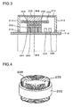
- FIG. 3 shows the rotating electric machine 200 or the rotating electric machine 202 in FIG. 1 in a sectional view. Since the rotating electric machine 200 and the rotating electric machine 202 adopt structures that are substantially identical to each other, the structure of the rotating electric machine 200, chosen as a representative example, is described below. It is to be noted that while very significant advantages are achieved by adopting the structure described below in both the rotating electric machines 200 and 202, it is not strictly necessary that the structure be adopted in both rotating electric machines 200 and 202 and that advantages unique to the present invention will be achieved as long as the structure is adopted in at least either rotating electric machine.
- a stator 230 which includes a stator core 232 and a stator winding 238, is held. While the stator 230 may adopt either a concentrated winding system or a distributed winding system, a stator 230 with a winding achieved by adopting the distributed winding system will have characteristics whereby reluctance torque is generated more readily.
- a rotor 250 is rotatably held via a gap 222.
- the rotor 250 includes a rotor core 252 and permanent magnets 254.
- the rotor core 252 is fixed to a shaft 218.
- the housing 212 includes a pair of end brackets 214 at which bearings 216 are disposed.
- the shaft 218 is rotatably held by these bearings 216.
- the rotor core 252 is constituted with numerous electromagnetic steel sheets laminated one on top of another along a direction in which the rotational axis extends.
- the electromagnetic steel sheets in the embodiment described below each include magnet insertion holes 272 (see FIG. 7 ), at which the permanent magnets 254 are inserted, formed therein.
- the magnet insertion holes 272 instead of assuming a uniform length along the circumferential direction in which the rotor rotates, the magnet insertion holes 272 each take on n different lengths along the circumferential direction.
- the side elevation of the section of a magnet insertion hole 272 projected from the stator side varies to take on an appearance of a plurality of rectangular insertion holes set one after another along the rotor axis, as in the embodiments described in reference to FIG. 11 and subsequent figures.
- a rotor position sensor 224 that detects the positions of the magnetic poles at the rotor 250 and a rotating speed sensor 226 that detects the rotating speed at which the rotor 250 rotates are disposed at the shaft 218.
- the outputs from these sensors 224 and 226 are taken into the control circuit 248 shown in FIG. 2 .
- the control circuit 248 outputs a control signal generated based upon the outputs thus taken in to the drive circuit 652.
- the drive circuit 652 outputs a drive signal generated based upon the control signal to the power module 610.
- the power module 610 engages in switching operation so as to convert the DC power provided from the battery 180 to three-phase AC power.
- the three-phase AC power resulting from the conversion is supplied to the stator winding 238 shown in FIG. 3 and, as a result, a rotating magnetic field is generated at the stator 230.
- the frequency of the three-phase AC current is controlled based upon the detection value provided from the rotating speed sensor 226, whereas the phases of the three-phase AC current relative to the rotor 250 are controlled based upon the detection value provided by the rotor position sensor 224.
- the stator winding 238 at the stator 230 shown in FIG. 3 may adopt either the distributed winding system or the concentrated winding system.
- FIG. 4 provides an external view of the stator 230 adopting the distributed winding system.
- phase windings are wound around the stator core 232 so as to house a given phase winding in two slots 24 set apart from each other across a plurality of slots 24.
- the stator winding 238 shown in FIG. 4 can be constituted with coils 233 wound by adopting the distributed winding system.
- the magnetic field formed via the stator winding 238 adopting the distributed winding system assumes magnetic flux distribution characteristics more closely resembling the sine waves compared to the magnetic flux distribution characteristics of the magnetic field formed with a stator winding adopting the concentrated winding system described later.
- a reluctance torque can be generated readily in a rotating electric machine equipped with a stator 230 adopting the distributed winding system and that the voltage induced in a high-speed rotational range can be more effectively suppressed in such a rotating electric machine.
- the rotating electric machine thus assures characteristics required of a drive rotating electric machine in an electric vehicle in which it is desirable to generate a drive torque even in the high-speed rotation range.
- FIG. 5 a stator winding adopting the concentrated winding system is described.
- FIG. 5 and FIGS. 6(a), 6(b) and 6(c) present an example of a stator winding adopting the concentrated winding system.
- coils 233 are wound at each of teeth 236 formed at the stator 230.
- the stator core 232 is divided into T-shaped blocks each made up with a tooth 236 and a core back portion 235, a bobbin 234 is fitted at each tooth 236, as shown in FIG. 6(a) , and the coils 233 is formed by winding a coated conductor around the bobbin, as shown in FIGS.
- stator 230 is configured as an integrated unit.
- FIG. 7 presents perspective views of the stator 230 and the rotor 250 constituting part of the rotating electric machine 200.
- FIG. 7(a) shows the rotor 250 disposed on the inner side of the stator 230, whereas the illustration in FIG. 7(b) does not include the stator winding 238 and the coils 233, so as to show the shape of the stator core 232 with better clarity.
- FIG. 7(c) which does not include an illustration of the rotor 250, shows the stator core 232 formed by laminating electromagnetic steel sheets one on top of another.
- the stator core 232 includes slots 24 formed along the entire circumference thereof, at which the stator winding 238 is inserted.
- FIG. 7(a) shows the rotor 250 disposed on the inner side of the stator 230, whereas the illustration in FIG. 7(b) does not include the stator winding 238 and the coils 233, so as to show the shape of the stator core 232 with better clarity.
- FIG. 7(c)
- FIG. 7(d) shows the rotor core formed by laminating electromagnetic steel sheets one on top of another along the rotational axis.
- Each electromagnetic steel sheet used to constitute the rotor core has magnet insertion holes 272 formed along the entire circumference thereof.
- Reference numeral 272 is appended only to some of the magnet insertion holes so as not to crowd the illustration.
- An auxiliary magnetic pole, through which the magnetic flux generated along a q-axis passes is formed in the area of the rotor core located between successive magnet insertion holes 272, and a reluctance torque is generated due to the difference between the magnetic resistance at the magnetic circuit traveling through the auxiliary magnetic pole and the magnetic resistance at a d-axis magnetic circuit.
- the magnetic poles at the rotor are each formed with a permanent magnet constituted with magnet pieces disposed in a single column, and an auxiliary magnetic pole is formed between successive magnet insertion holes.
- an auxiliary magnetic pole is formed between the magnet pieces disposed in two columns and the magnet pieces disposed in the next two columns.
- FIG. 7(e) shows permanent magnets 254 and 255 inserted in the magnet insertion holes. While the permanent magnets 254 and 255 are each made up with several magnet pieces, as will be explained later, FIG. 7(e) does not show the individual magnet pieces.
- the stator 230 in FIG. 7 includes the stator core 232 and the stator winding 238, which is constituted with the coils 233 inserted at the slots 24 in the stator core 232.
- the rotor 250 is formed by stacking electromagnetic silicon steel sheets with magnet insertion holes at which magnets are to be inserted, formed therein, and the permanent magnets 254 and the permanent magnets 255 are embedded in the magnet insertion holes.
- the magnetomotive force imparted from a permanent magnet 254 or a permanent magnet 255 inserted at a magnet insertion hole in the embodiment changes along the rotational axis of the rotating electric machine.
- the width of the magnet assumed along the circumferential direction does not remain uniform along the rotational axis of the rotating electric machine, i.e., the circumferential width of the magnet changes.
- the use of permanent magnets adopting such a shape reduces the extent of torque ripple.
- FIG. 8 shows the stator 230 and the rotor 250 in a sectional view taken along B-B in FIG. 3 . It is to be noted that FIG. 8 does not include illustrations of the housing 212, the shaft 218 and the stator winding 238.
- On the inner side of the stator core 232 numerous slots 24 and teeth 236 are formed at equal intervals over the entire circumference. In order to avoid crowding, reference numerals 24 and 236 are appended only to some of the slots and teeth.
- a slot insulator (not shown) is disposed inside the slots 24, and a plurality of phase windings corresponding to u through w phases, to constitute the stator winding 238, are inserted in the slots 24.
- the stator winding 238 in the embodiment may be formed by adopting the distributed winding system or the concentrated winding system.
- each magnetic pole is formed with a permanent magnet made up with magnet pieces disposed in a single column.
- magnetic poles may each be formed with a plurality of permanent magnets disposed side-by-side along the circumferential direction, with the plurality of permanent magnets constituted with magnet pieces disposed over a plurality of columns set side-by-side along the circumferential direction, as explained earlier.
- the magnetic flux density per pole can be raised since each magnetic pole is formed with a plurality of permanent magnets, and thus, the output of the rotating electric machine increases.
- Auxiliary magnetic poles 282, through which the q-axis magnetic flux is to pass, are each formed between a given magnetic pole at the rotor and the next magnetic pole.
- a magnetic circuit with a large sectional area is formed so as to reduce the magnetic resistance at each auxiliary magnetic pole and thus, a significant reluctance torque is generated.
- the ratio of the reluctance torque to the overall torque generated in the rotating electric machine is raised, which, in turn, makes it possible to keep the internally induced voltage to a relatively low level in the high speed rotation range. Consequently, an advantage is achieved in that the current supplied during high-speed rotation is raised for the source voltage so as to increase the output torque in a high-speed traveling state.
- the rotor core 252 of the rotor 250 shown in FIG. 8 includes the magnet insertion holes 272 formed therein based upon the shapes of the magnet pieces constituting the permanent magnets as described below and the permanent magnets embedded in the magnet insertion holes 272 are fixed with an adhesive or the like.
- the permanent magnets function as magnetic field poles (simply referred to as magnetic poles in the description of the embodiment) of the rotor 250.
- the permanent magnets are magnetized along the radial direction, with the orientation of the magnetization alternated from one magnetic field pole to the next magnetic field pole.
- a side surface of the permanent magnet forming a given magnetic pole, located toward the stator is magnetized to have N polarity and that its surface facing toward the central axis is magnetized to have S polarity
- the side surface of the permanent magnet forming an adjacent magnetic pole, located toward the stator is polarized to have S polarity and its surface facing toward the central axis is magnetized to have N polarity.
- the permanent magnets are disposed so as to form magnetic poles with alternate polarities over the entire circumference.
- sixteen permanent magnets are disposed with equal intervals, and thus, sixteen magnetic poles are formed at the rotor 250.
- an auxiliary magnetic pole is formed between successive magnetic poles, the q-axis magnetic circuit is formed via the auxiliary magnetic pole and the magnetic resistance at the auxiliary magnetic pole is kept down, making it possible to generate a large reluctance torque.
- the utilization ratio of the reluctance torque in the output torque represented by the sum of the magnetic torque attributable to the permanent magnets and the reluctance torque can be raised in the embodiment.
- the induced voltage can be kept to a low level, resulting in an advantage in that the extent to which the torque generated in a high-speed rotation state is reduced can be reduced.
- FIG. 9 shows the process of magnetizing the permanent magnets.
- a permanent magnet is indicated by reference numeral 254 or reference numeral 255.
- FIG. 8 shows the magnet insertion holes 272 at which the permanent magnets are inserted and held, although FIG. 8 does not include an illustration of the permanent magnets that are present within the magnet insertion holes 272. While the permanent magnets 254 and 255 are magnetized in opposite directions and the permanent magnets 255 assume a shape achieved by rotating a permanent magnet 254 by 180° along the rotational axis, the permanent magnets 254 and 255 are otherwise substantially similar in form and characteristics, and accordingly, the following description is given in reference to the permanent magnets 254.
- the permanent magnets 254 may be magnetized through the polarization in advance and then embedded at the rotor core 252, or they may be inserted at the rotor core 252 in an un-polarized state and then polarized by applying an intense magnetic field thereto. Once magnetized, the permanent magnets 254 exert a strong magnetic force. This means that if the permanent magnets 254 are polarized before they are fitted at the rotor 250, the strong attracting force occurring between the permanent magnets 254 and the rotor core 252 is likely to present a hindrance during the permanent magnet installation process. Furthermore, the strong attracting force may cause foreign matter such as iron dust to settle on the permanent magnets 254. For this reason, better rotating electric machine productivity is assured by magnetizing the permanent magnets 254 and 255 after they are inserted in the magnet insertion holes 272 at the rotor core 252.
- the permanent magnets 254 and 255 may be neodymium-based sintered magnets, the primary constituents of which are neodymium, iron and boron, samarium-based sintered magnets, the primary constituents of which are samarium and cobalt, ferrite magnets or neodymium-based bonded magnets.
- the residual magnetic flux density of the permanent magnets 254 and 255 is approximately 0.4 to 1.3 T.
- FIG. 9 shows the positional arrangement with which permanent magnets are disposed, viewed from the stator side. While the permanent magnets are actually held inside the magnet insertion holes at the rotor core, the figure does not include an illustration of the rotor core so as to show the permanent magnet positional arrangement with better clarity.
- the permanent magnets 254 and 255 are disposed over the entire circumference of the rotor so that a permanent magnet 254 having N polarity at the surface thereof facing toward the stator and a permanent magnet 255 having S polarity at its surface facing toward the stator are set in an alternate pattern with a pole pitch ⁇ p along the circumferential direction. 360° representing a full cycle in electrical angle is equivalent to twice the pole pitch ⁇ p.
- the length ENC over which the magnets each extend along the circumference of the rotor is expressed in electrical angle.
- the magnet piece 255a and the magnet piece 255b disposed side-by-side along the rotor axis are offset so as to form steps along the circumference of the rotor in a direction matching the direction in which the magnet piece 254a and the magnet piece 254b disposed side-by-side along the rotor axis are offset relative to each other so as to form steps.
- Torque pulsations occurring in a motor with permanent magnets include a cogging torque generated in a no-load state.
- cogging torque refers to torque pulsations that occur due to the variance in the magnetic resistance between the rotor magnets and iron constituting the stator core, which changes from one position to another at the rotor.
- the cycle of the cogging torque occurring in a three-phase motor is 60° in electrical angle.
- FIG. 10 shows waveforms of torque pulsations.
- the waveforms of cogging torque pulsations are determined in correspondence to a specific magnet piece position taken along the circumferential direction. In other words, if the magnet piece position is shifted along the circumferential direction, the torque pulsation peak and the torque pulsation trough also shift. If the magnet pieces are offset relative to each other by 30° along the circumferential direction as has been described in reference to FIG. 9 , the cogging torque peak and the cogging torque trough also become offset by 30°, and the combined cogging torque pulsations cancel each other out, resulting in reduced overall torque pulsation, as shown in the figure.
- the cycle of the fundamental wave of the cogging torque pulsations is equal to 60° in electrical angle, which is equivalent to a sixth-order cycle relative to the fundamental frequency of the power source.
- torque pulsations of odd numbered orders can be eliminated but torque pulsations of even-numbered orders, i.e., of 2nth orders (n is an integer), cannot be eliminated.
- FIG. 11(b) shows magnet pieces adopting desirable shapes and disposed in a desirable positional arrangement
- FIG. 11 (a) shows magnet pieces with undesirable shapes and disposed in an undesirable positional arrangement for purposes of comparison.
- the positional arrangement adopted in conjunction with the magnet pieces assuming the shapes shown in FIG. 11(b) will be referred to as a "block skew" formation
- the positional arrangement of the magnet pieces assuming the undesirable shapes shown in FIG. 11 (a) will be referred to as a stepped skew formation.
- FIG. 11 (b) shows magnet pieces adopting desirable shapes and disposed in a desirable positional arrangement
- FIG. 11 (a) shows magnet pieces with undesirable shapes and disposed in an undesirable positional arrangement for purposes of comparison.
- two types of magnet pieces 254a and 254b or two types of magnet pieces 255a and 255b are disposed next to each other along the rotor axis running along the rotational axis.
- the permanent magnet 254 or 255 is formed.
- the difference between the lengths of the magnet pieces constituting the permanent magnet, measured along the circumference of the rotor, is equal to approximately ⁇ /3 radian in electrical angle, i.e., equivalent to approximately 60°.
- a line A in the undesirable stepped skew formation shown in FIG. 11(a) is substantially in alignment with a line F in the block skew formation.
- a line B in the stepped skew formation is substantially in alignment with a line E in the block skew formation.
- lines C and D in the stepped skew formation are respectively in substantial alignment with lines G and H in the block skew formation.
- a line ⁇ indicates the central position assumed at each magnet piece along the circumference of the rotor and that the central lines passing through the centers of the magnet pieces 254a and 254b constituting the permanent magnet 254 are substantially in alignment with each other.
- a field pole is formed in the embodiment with a permanent magnet made up with magnet pieces disposed in a single column, the center of the magnetic pole and the central lines passing through the centers of the magnet pieces are substantially in alignment.
- the center of the magnetic pole and the central lines ⁇ passing through the centers of the magnet pieces are substantially in alignment with each other, and each magnet piece takes on a symmetrical shape achieving symmetry along the circumferential direction relative to the central line passing through the center of the magnetic pole.
- the difference between the lengths of the magnet pieces measured along the circumference of the rotor is set to a value equivalent to approximately 120°/n in electrical angle.
- n is 2, and accordingly, the difference between the length of the magnet piece 254a and the length of the magnet piece 254b measured along the circumferential direction is equivalent to approximately 60° in electrical angle.
- the shapes of the magnet pieces 254a and 254b and the positional relationship between the magnet pieces 254a and 254b are the same as those of the magnet pieces 255a and 255b, but the magnet pieces 254a and 254b are magnetized along a direction opposite from the direction in which the magnet pieces 255a and 255b are magnetized.
- the magnet piece 254b and the magnet piece 255b ranging over a greater length along the circumferential direction are disposed.
- the magnet quantity of the magnet pieces 254b and 255b is greater than that of the magnet pieces 254a and 255a and thus, the magnetic torque generated on the one side is greater than that generated on the other side.
- 11(b) shows an auxiliary magnetic pole 282 formed between the magnet pieces 254a and 255a and an auxiliary magnetic pole 282 formed between the magnet pieces 254b and 255b.
- the part of the auxiliary magnetic pole 282 formed between the magnet pieces 254a and 255a, located on the other side along the axial direction ranges over a greater length along the circumferential direction compared to the part of the auxiliary magnetic pole 282 formed between the magnet pieces 254b and 255a, located on the one side along the axial direction.
- This means that a greater reluctance torque is generated with the magnetic flux passing through the auxiliary magnetic pole on the other side along the axial direction, compared to the reluctance torque generated on the one side.
- the combined torques each representing the sum of the magnetic torque and the reluctance torque generated on either side, act to reduce the torque difference manifested by the two combined torques along the axial direction.
- both the magnetic torques and the reluctance torques work along a matching direction in which a thrust force is generated along the axis, resulting in a significant thrust force manifesting in the axial direction.
- the bearings are bound to be adversely affected by this axial thrust force.
- the thrust force manifesting along the axial direction tends to cause a problem when an accelerating or decelerating gear is engaged with the shaft of the rotating electric machine, as the axial thrust force may alter the interlocking position at which the gear engages or the gear may be subjected to excessive force.
- FIG. 12 shows another embodiment.
- FIG. 12(a) illustrates an undesirable stepped skew formation whereas
- FIG. 12(b) illustrates a desirable block skew formation.
- a thrust force is generated along the axial direction. This thrust force is likely to affect the mechanical system adversely as it may offset the center of the rotor relative to the stator or the bearings may be subjected to excessive force applied along the axial direction. There is an added concern that the mechanical loss in the rotating electric machine is likely to increase.
- the undesirable stepped skew formation shown in FIG. 12(a) has a function of reducing the thrust force.
- the permanent magnets and the auxiliary magnetic pole forming a q-axis magnetic flux circuit are each offset along the circumferential direction as it ranges from one end taken along the rotational axis toward the center of the rotational axis and then they each resume the initial position taken along the circumferential direction beyond the center of the rotational axis so as to achieve symmetry relative to the center of the rotational axis.
- the thrust force can be reduced.
- the arrangement is not as desirable as those shown in FIG. 11(b) and FIG.
- the permanent magnet 254 is made up with two types of magnet pieces 254a and 254b and the permanent magnet 255 is made up with two types of magnetic pieces 255a and 255b in the desirable positional arrangement shown in FIG. 12(b) .
- Lines ⁇ are central lines running through the centers of the magnet pieces 254a and 254b and the magnet pieces 255a and 255b taken along the circumferential direction, and the magnet pieces constituting each permanent magnet are disposed so that the central lines ⁇ running through the individual magnet pieces form a substantially single straight line extending along the rotational axis.
- the centers of the magnetic poles formed with the permanent magnets 254 and 255 are in alignment with the central lines ⁇ running through the centers of the magnet pieces.
- FIG. 12(b) are similar in their external appearance to the permanent magnets described earlier in reference to FIG. 7(e) and the permanent magnets in FIG. 12(b) are also disposed exactly as the permanent magnets in FIG. 7(e) are disposed so as to form magnetic poles having N polarity and S polarity.
- the effect achieved with regard to torque pulsation by adopting the positional arrangement shown in FIG. 12(b) is identical to that described in reference to FIG. 11(b) .
- the magnet pieces 254a and 255b are formed so as to range over substantially matching lengths along the circumferential direction and the magnet pieces 254b and 255a are formed so as to range over substantially matching lengths along the circumferential direction.
- the difference between the lengths of the magnet pieces 254a and 254b measured along the circumferential direction and the difference between the lengths of the magnet pieces 255a and 255b measured along the circumferential direction are each equivalent to 60° in electrical angle.
- the difference between the lengths of magnet pieces constituting the permanent magnets 254 and 255 measured along the circumferential direction is set to a value equivalent to approximately 120°/n in electrical angle.
- an auxiliary magnetic pole 282 formed between each pair of successive magnetic poles, one having N polarity and the other having S polarity, includes two sides set next to each other along the axial direction, which are offset relative to each other along the circumferential direction.
- the direction in which the two sides of a given auxiliary magnetic pole 282, among the plurality of auxiliary magnetic poles 282 formed consecutively along the circumferential direction is offset relative to each other is the opposite of the offsetting direction in which the two sides of the immediately preceding or succeeding auxiliary magnetic pole 282 are offset.
- the auxiliary magnetic pole 282, located to the right of the N pole in FIG. 12(b) is formed so that it is offset to the right along the circumferential direction as it ranges from the other side toward the one side along the axial direction
- the auxiliary magnetic pole 282 located to the left of the N pole in the figure is formed so that it is offset to the left along the circumferential direction as it ranges from the other side toward the one side along the axial direction.
- the offsetting direction is switched to the opposite for every second auxiliary magnetic pole, making it possible to cancel out the thrust force components.
- FIG. 12(b) The structural arrangement shown in FIG. 12(b) is more advantageous compared to that shown in FIG. 12(a) in that it requires fewer magnets. This ultimately means that since the numbers of manufacturing steps required as part of the laminating process through which the electromagnetic steel sheets are laminated one on top of another along the axial direction in order to form the rotor, as part of the magnet insertion process, as part of the rotor assembly process and the like can be greatly reduced, the manufacturing costs can be lowered.
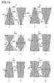
- FIG. 13(a), FIG. 13(b) and FIG. 13(c) each show a block skew variation with magnet pieces assuming desirable shapes disposed in a desirable positional arrangement.
- Each of these positional arrangements achieves a cogging torque canceling effect, equivalent to that achieved by adopting the two step skew formation described in reference to FIG. 12(a) as an undesirable example.
- the individual magnet pieces constituting a permanent magnet are disposed so that a substantially single straight line ⁇ runs along the axial direction through the centers of the magnet pieces.
- the permanent magnets is formed in a shape substantially achieving symmetry with regard to the one side and the other side ranging next to each other along the axial direction, the rotor is subjected to hardly any thrust force attributable to the magnetic torque. Assuming that there is no manufacturing error, in theory, there will be no thrust force. Furthermore, assuming that there is no manufacturing error, the structure does not allow any thrust force attributable to the reluctance torque to occur along the axial direction.
- the magnet insertion holes at which the magnet pieces are inserted are not mentioned in the description given in reference to FIG. 11(b), FIG. 12(b) and FIGS. 13(a) through 13(c) , the magnet insertion holes at which the magnet pieces are to be inserted are formed at each of the electromagnetic steel sheets to constitute the rotor core in a size slightly larger than the external dimensions of the magnet pieces.
- the magnet insertion holes are formed slightly larger than the external dimensions of the various magnet pieces so as to facilitate the magnet piece insertion process.
- FIGS. 13(a) through 13(c) each include an auxiliary magnetic pole 282 formed between the magnet pieces 254a through 254d constituting a permanent magnet 254 having N polarity and magnet pieces 255a through 255d constituting a permanent magnet 255 having S polarity.
- n 2
- the difference between the various lengths taken along the circumferential direction is equivalent to 120°/n in electrical angle.
- n is an integer equal to or greater than 2.
- two different lengths are assumed along the circumferential direction for the magnet pieces constituting each permanent magnet.
- n is 2 in the variations.
- 120°/n is calculated to be 120°/2, indicating that the difference between the lengths taken along the circumferential direction is equivalent to 60° in electrical angle.
- the magnet pieces 254a, 254b, 254c and 254d or the magnet pieces 255a, 255b, 255c and 255d are disposed along the axial direction from the other side toward the one side of the axis.
- the two magnet pieces 254b and 254c located in the central area along the axial direction are identical to each other in shape, and the two magnet pieces 255b and 255c located in the middle area along the axial direction are also identical to each other in shape.
- the pair of magnet pieces 254b and 254c and the pair of magnet pieces 255b and 255c can each be prepared as a single integrated magnet piece, the overall number of magnet pieces can be reduced, which, in turn, may lead to improved productivity
- FIG. 11(b) and FIG. 12(b) require fewer magnet pieces compared to those shown in FIGS.13(a), 13(b) and 13(c) and thus, the structural examples presented in FIGS. 11(b) and 12(b) assure better productivity.
- the structural arrangements shown in FIG. 11(b) and FIG. 12(b) allow the rotor core to be machined with better ease compared to the structural arrangements shown in FIGS. 13(a), 13(b) and 13(c) .
- the magnet pieces can be inserted at the magnet insertion holes in the rotor core 252 in a fully assembled state, better productivity is also assured with regard to magnet piece insertion.
- FIGS. 13(a) through 13(c) assume a uniform length along the axial direction so as to assure superior magnet productivity when manufacturing neodymium-based or samarium/cobalt-based sintered magnets.
- the magnet pieces 254a and 254d or the magnet pieces 255a and 255d, located toward the two ends of the rotational axis in FIG. 13 (b) amount to a relatively small magnet quantity
- the magnet pieces 254b and 254c or the magnet pieces 255b and 255c, located over the central area along the rotational axis amount to a larger magnet quantity. This means that a greater magnetic torque is imparted over the central area along the axial direction and less magnetic torque is imparted toward the two ends along the axial direction.
- the structural design shown in FIG. 13(b) is more effective than the structural design shown in FIG. 13(c) .
- the structure shown in FIG. 13(b) is most effective, the structure shown in FIG. 13(a) is the second most effective and the structure shown in FIG. 13(c) is the least effective in reducing the magnetic flux leakage from the ends of the rotor facing opposite each other along the axial direction.
- the shapes of the magnetic poles and the auxiliary magnetic poles in FIG. 14(a) and FIG. 14(b) are determined by the structures of the permanent magnets each made up with three types of magnet pieces ranging over different lengths along the circumferential direction and by the positional arrangements with which the permanent magnets are disposed.
- the permanent magnet 254 is made up with a magnet piece 254a, a magnet piece 254b and a magnet piece 254c, and central lines ⁇ running through the centers of the magnet pieces 254a, 254b and 254c, each taken along the circumferential direction, are in alignment with one another.
- a magnetic pole is formed with a single permanent magnet and thus, the central line running through the center of the magnetic pole is substantially in alignment with the central lines ⁇ each running through the center of a magnet piece.
- auxiliary magnetic poles 282 formed one after another along the circumferential direction, each assume a shape inclining along the circumferential direction, the direction of inclination is alternately switched.
- thrust force components attributable to the reluctance torque cancel each other out and thus, hardly any thrust component manifests in the rotor as a whole.
- FIG. 14(b) achieves an advantage similar to that of the embodiments shown in FIG. 13 in that the cogging torque component with a 60° cycle in electrical angle is mostly eliminated, the cogging torque with a cycle half the cycle of the cogging torque component eliminated through the embodiments shown in FIG. 13 , i.e., a 30° cycle, is also eliminated through the embodiment shown in FIG. 14(b) , thereby achieving an even greater torque pulsation reducing effect.
- the side surfaces of the magnet pieces that face opposite each other on each side along the circumferential direction over an ⁇ -b section are offset by 20° in electrical angle relative to the side surfaces of the magnet pieces that face opposite each other over a c-d section and the magnet pieces that face opposite each other over an e-f section, which, in turn, are offset from each other by 20° in electrical angle on each side, in the structural arrangement shown in FIG. 14(b) .
- the waveform of the overall cogging torque is equivalent to the combination of the individual waveforms, offset relative to each other by 20°, as shown in FIG. 15 .
- FIGS. 16(a1) through 16(e1) show block skew variations. Cogging torque components are canceled out by each other with magnet pieces disposed as shown in any of the variations.
- the magnet pieces used in each variation are disposed so as to achieve symmetry relative to the straight line running along the axial direction by passing through the center of each magnet piece, assumed along the circumferential direction.
- Torque pulsations of higher orders can be eliminated by increasing the number n of magnet piece types used in conjunction with the structural arrangements shown in FIG. 16(a1) through 16 (e1).
- FIG. 16(a2) through 16(e2) show structural designs with which torque pulsations of higher orders can be reduced.
- the block skew formations, each made up with two different types of magnetic pieces, as shown in FIG. 16(a1) through 16(e1) can be modified by replacing the two different types of magnet pieces with a single type of trapezoidal (isosceles trapezoid) permanent magnet or magnet piece, as shown in FIG. 16(a2) through 16(e2) .
- trapezoidal structure will be referred to as a trapezoidal skew formation.
- each permanent magnet shown in FIG. 16(a2) is equivalent to that achieved by inclining, i.e., skewing, the left side and the right side of the bottom magnet piece in FIG. 16(a1) inward by an extent equivalent to 30° in electrical angle and by skewing the left side and the right side of the top magnet piece inward by an extent equivalent to 30° in electrical angle. It is assumed that the lengths of the sides of the individual magnet pieces in FIG. 16(a1) extending along the axial direction are equal to each other. Likewise, each trapezoidal magnet piece on the top side in FIG. 16(b2) corresponds to a block skew unit made up with the first and second magnet pieces from the top in FIG.
- each trapezoidal magnet piece on the bottom side in FIG. 16(b2) corresponds to a block skew unit made up with the third and fourth magnet pieces from the top in FIG. 16(b1) .
- the difference between the length of the upper base and the length of the lower base of the trapezoid is equivalent to 120° in electrical angle.
- each permanent magnet made up with a plurality of magnet pieces assume a smaller length at its ends facing opposite each other along the axial direction, i.e., the length of the top side and the bottom side of the permanent magnet in the figure is smaller than the length over which the permanent magnet ranges along the circumferential direction through its center taken along the axial direction.
- magnetic flux leakage tends to occur more readily.
- the length of the N pole ends and the length of the S pole ends do not match and, as a result, a greater extent of magnetic flux leakage occurs at the N pole compared to the extent of magnetic flux leakage occurring at the S pole.
- an asymmetrical condition tends to occur readily between the N pole and the S pole, which, in turn, is bound to cause low order torque ripple.
- the extent of magnetic flux leakage occurring at the ends facing opposite each other along the axial direction tends to be greater in the embodiments shown in FIGS. 16(c1) and 16(c2) compared to the extent of magnetic flux leakage occurring at the ends facing opposite each other along the axial direction in the embodiments shown in FIGS.
- the two types of magnet pieces used in the structural examples shown in FIG. 17(a) and FIG. 17(c) range along the circumferential direction over lengths manifesting a difference equivalent to 60° in electrical angle, as has been described in reference to FIGS. 11 and 12 .
- each two types of magnet pieces disposed consecutively, among the three types of magnet pieces arranged as shown in FIG. 17(b) range along the circumferential direction over lengths manifesting a difference equivalent to 40° in electrical angle, as has been described in reference to FIG. 14 .
- a skew formation achieved by using n different types of magnet pieces include the n types of magnet pieces manifesting a difference in the length, measured along the circumferential direction, equivalent to 120°/n in electrical angle, which are disposed one after another along the axial direction.
- the waveforms of the cogging torque components manifesting in such a block skew formation have already been described in reference to FIG. 15 . While there still remains the cogging torque component with a 20° cycle in electrical angle, the cogging torque components with the 60° cycle in electrical angle and the cogging torque component with the 30° cycle in electrical angle are reduced as has been explained in reference to FIG. 15 . It is to be noted that the 20° cycle in electrical angle is equivalent to the component of the 18th order in time relative to the power source frequency.
- FIGS. 17(d), 17(e) and 17(f) are similar to those shown in FIGS. 17(a), 17(b) and 17(c) except that the differences between the lengths of the magnet pieces, measured along the circumferential direction, are reduced to half the differences in FIGS. 17(a), 17(b) and 17(c) .
- the difference between the lengths of the two types of magnet pieces, measured along the circumferential direction is equivalent to 30° in electrical angle, whereas in the structural arrangement shown in FIG.
- the cycles of cogging torque components manifesting in a three-phase motor are equivalent to 60°, 30° and 15° in electrical angle, which respectively correspond to the sixth order, the twelfth order and the 18th order in time relative to the power source fundamental frequency.
- a 6nth-order component with a (360/6n)° cycle i.e., a 60/n° cycle, manifests as a cogging torque or a torque ripple.
- the 12th-order torque pulsations alone are eliminated without canceling out the sixth-order torque pulsations in a motor manifesting a more significant twelfth order cogging torque component in time compared to the sixth order cogging torque component in time.
- the cogging torque with the 30° cycle can be eliminated by adopting any of the block skew formations shown in FIGS. 17(d), 17(e) and 17(f) .
- These embodiments are advantageous in that the torque does not decrease significantly. While the torque normally tends to decrease significantly when the skew angle is large, the torque reduction can be lessened by adopting any of the positional arrangements shown in the figures in conjunction with the magnet pieces structured as described above.
- FIG. 18 presents another embodiment.
- the shape of the space inside the magnet insertion holes formed at the core, at which magnets are fitted, does not need to exactly match the shape of the magnet pieces.
- the magnet pieces are each formed in a rectangular parallelepiped shape and the magnet insertion holes to house the rectangular parallelepiped magnet pieces have an internal space slightly larger than the magnet pieces so as to allow the magnet pieces to be inserted with ease.
- the embodiment shown in FIG. 18 is unique in that the permanent magnets 254 and 255 are each made up with a single magnet piece.
- the permanent magnets 254 and 255 assume a substantially trapezoidal shape (isosceles trapezoid), viewed from the stator side, with the lengths of the upper base and the lower base of the trapezoid, located at the two ends facing opposite each other along the rotational axis of the rotor 250 manifesting a difference equivalent to 120° in electrical angle.
- Magnet insertion holes 272 at which the permanent magnets 254 and 255 are to be inserted are formed by laminating a plurality of electromagnetic steel sheets, each having substantially rectangular holes formed therein, one on top of another.
- the magnet insertion holes 272 in the embodiment are each formed in two stages set next to each other along the rotor axis.
- FIG. 18(b) shows the shape of the magnet insertion holes 272 at the rotor core 252, viewed from the rotational axis.
- An ⁇ -b section and an c-d section taken at the positions respectively indicated by the one-point chain line ⁇ -b and the one-point chain line c-d in FIG. 18(a) are notated as a-b and c-d respectively in FIG. 18(b) .
- the ⁇ -b section and the c-d section are offset relative to each other by an extent equivalent to a single magnetic pole.
- the magnetic poles and the auxiliary magnetic poles formed at the rotor core achieve rotational symmetry and thus, if the electromagnetic steel sheets are laminated one on top of another with an offset equivalent to a single pole, the auxiliary magnetic poles B and D are set with an offset equivalent to 30° in electrical angle relative to the auxiliary magnetic poles A and C in FIG. 18(a) .
- the electromagnetic steel sheets with magnet insertion holes formed in matching shapes can be used to form two-stage auxiliary magnetic poles in the embodiment.
- auxiliary magnetic poles 282A and 282B By assembling the electromagnetic steel sheets with magnet insertion holes with matching shapes formed therein with an offset along the circumferential direction, auxiliary magnetic poles 282A and 282B to function as auxiliary magnetic poles can be formed as shown in FIG. 18(a) .
- air gaps 258, to act as magnetic voids are each formed between an auxiliary magnetic pole 282A and the closest permanent magnet 254 or between an auxiliary magnetic pole 282B and the closest permanent magnet 255.
- the plurality of auxiliary magnetic poles 282, inclining along the circumferential direction, are formed one after another along the circumferential direction by alternately switching the inclining direction with a uniform angle of inclination, achieving an advantage in that no thrust force attributable to the reluctance torque is generated along the axial direction.
- the rotor core can be constituted with electromagnetic steel sheets of a single type, formed identically to each other, which are rotated along the circumferential direction in order to form the auxiliary magnetic poles 282A and 282B.
- the manufacturing cost can be reduced.
- the structure does not include magnets split along the axial direction, a smaller quantity of magnets is required, which, in turn, helps reduce the number of steps to be followed when embedding the magnets in the rotor.
- each auxiliary magnetic pole 282 constituted of the core material present between magnetic poles, facing opposite each other along the rotational axis, are offset relative to each other along the circumferential direction by 30° in electrical angle. While reluctance torque is bound to occur at the auxiliary magnetic poles, the reluctance torque generated at such an auxiliary magnetic pole will also manifest torque pulsations with a 30° offset.
- trapezoidal skew formations can be achieved as shown in FIG. 16 in correspondence to the block skew formation illustrated in FIG. 11(b) , FIG. 12(b) and FIG. 13
- trapezoidal skew formations can be achieved as shown in FIGS. 19(a) through 19(f) in correspondence to the block skew formations illustrated in FIGS. 17(a) through 17(f) respectively.
- FIGS. 19(a) through 19(c) each feature a trapezoidal skew formation, so as to reduce torque pulsations of higher orders as well.
- the arrangements shown in FIGS. 19(d), 19(e) and 19(f) corresponding to those shown in FIGS. 17(d) through 17(f) respectively, achieve advantages similar to those of the embodiments shown in FIGS. 17(d) through 17(f) with regard to torque pulsations.
- the structural designs shown in FIGS. 19(d), 19(e) and 19(f) each feature a trapezoidal skew formation, so as to reduce torque pulsations of higher orders as well.
- FIGS. 19(d), 19(e) and 19(f) each manifest a difference between the length of the upper base and the length of the lower base of the trapezoidal, measured along the circumferential direction, which is equivalent to 120° in electrical angle.
- the trapezoidal permanent magnets and magnet pieces in FIGS. 19(d), 19(e) and 19(f) each manifest a difference between the length of the upper base and the length of the lower base of the trapezoidal, measured along the circumferential direction, which is equivalent to 60° in electrical angle.
- FIG. 20(a) provides a three-dimensional illustration of a positional arrangement adopted in conjunction with trapezoidal permanent magnets. It shows a permanent magnet 254 having N polarity at its surface facing toward the stator and a permanent magnet 255 having S polarity at its surface facing toward the stator, disposed alternately to each other, with an auxiliary magnetic pole 282 formed between each pair of permanent magnets disposed next to each other. It is to be noted that while the permanent magnets 254 and 255 are embedded in the rotor core, the illustration does not show the rotor core.
- FIG. 20(b) is a sectional view taken from the stator side. While the permanent magnets 254 and 255 are disposed inside the rotor core, FIG. 20(b) shows them in a sectional view taken at a predetermined depth measured from the rotor surface, at which the permanent magnets are embedded.
- the embodiment shown in FIG. 20 may be adopted in conjunction with the skew formation shown in FIG. 19(e) , and the sectional view in FIG. 20(b) indicates the relationship between the magnets arranged as shown in FIG. 19(e) and the rotor core at which the auxiliary magnetic poles are formed. While the basic structure of the permanent magnets shown in FIG. 19(b) is basically identical to the structure of the permanent magnets shown in FIG.
- the permanent magnets 254 and 255 in FIG. 19(b) manifest a difference between the longer side and the shorter side, located at the two ends facing opposite each other along the rotational axis, expressed in electrical angle, which is different from the difference manifested by the longer side and the shorter side of the permanent magnets 254 and 255 in FIG. 19(e) .
- Auxiliary magnetic poles with three-stage offsets, such as those shown in FIGS. 19(b) and 19(e) can be formed without having to use numerous types of electromagnetic steel sheets, as has been explained in reference to FIG. 18 .
- the rotor core portions 232(a) and 232(c) are set along by assuming varying positional angles along the circumferential direction with the magnetic poles and the auxiliary magnetic poles achieving rotational symmetry in the embodiment.
- the rotor core can be formed with electromagnetic steel sheets with magnet insertion holes formed therein in a uniform shape through press machining executed by using a single die.
- the manufacturing cost can be reduced.
- magnetic torque pulsations of higher orders can be reduced and, at the same time, the torque pulsations attributable to the reluctance torque can be reduced to a greater extent compared to the extent of torque pulsation reduction achieved in conjunction with magnet insertion holes split into two stages.
- FIG. 21 illustrates varying relationships that may be achieved between the rotor core 252 and the magnet insertion holes 272 and between the magnetic poles and the auxiliary magnetic poles. While the structures adopted in the examples presented in FIGS. 21(a) through 21(d) are basically similar to one another, they feature magnets formed in shapes different from one another. The following description is given in reference to the example in FIG. 21 (a) , chosen as a representative.
- a magnet insertion hole 272 is formed at the rotor core 252. While a permanent magnet is inserted in the magnet insertion hole in reality, an illustration of the permanent magnet is not included.
- a d-axis magnetic flux 296 is generated with the permanent magnet inserted in the magnet insertion hole 272, and the d-axis magnetic flux 296 thus generated achieves inter-linkage with the stator winding.
- a magnetic pole portion 294 is formed at the core where the magnet insertion hole 272 is present, located toward the rotor, and the d-axis magnetic flux 296 is guided to the stator via the magnetic pole piece 294.
- Bridge portions 292 are formed between the magnet insertion hole 272 and the side surface of the rotor core 252 facing toward the stator.
- the bridge portions 292 are each located between the magnetic pole piece 294 and an auxiliary magnetic pole 282 and with the bridge portion 292 constricting the section of the magnetic circuit, a magnetically saturated state is achieved.
- the magnetic flux passing through the bridge portion 292 is restricted, and as a result, the magnetic flux leakage through the area between the magnetic pole piece 294 and the auxiliary magnetic pole 282 can be reduced.
- a magnetic circuit through which a q-axis magnetic flux 298 passes is formed at the auxiliary magnetic pole 282 and reluctance torque is thus generated.
- FIG. 21 (b) While the permanent magnet shown in FIG. 21 (b) is formed in a different shape, other structural features are substantially identical.
- the magnetic pole piece 294 formed between the permanent magnet and the outer circumference of the rotor core 252 is very narrow. The extent of magnetic flux leakage from the magnetic pole piece 294 to the auxiliary magnetic poles 282 is reduced via the bridge portions 292. While the surface of the permanent magnet located toward the stator assumes a curved contour in FIG. 21 (b) , the entire permanent magnet shown in FIG. 21(c) is formed in a circular arc shape running along the outer circumference of the rotor.
- FIG. 21(d) shows another structure with which magnetic flux leakage from the magnetic pole piece 294 to the auxiliary magnetic poles 282 can be reduced.
- the magnet insertion holes having been described in reference to FIGS. 11 through 14 and FIGS. 16 through 20 assume varying lengths along the circumference of the rotor in the direction of rotation.
- the sectional area of the magnetic circuit at each bridge portion 292 increases, which leads to an increase in the quantity of saturated magnetic flux.
- the extent of magnetic flux leakage through the area between the magnetic pole piece and the auxiliary magnetic pole is bound to rise, which, in turn, is likely to result in lowered efficiency and lower torque.
- the 21(d) includes magnetic voids 302 formed therein.
- the magnetic voids 302 are each constituted with an air gap formed at the time of electromagnetic steel sheet formation, and a bridge portion 292 is formed between each space 302 and the outer circumferential surface of the rotor core facing toward the stator.
- the sectional area of the magnetic circuit at the bridge portion 292 is narrowed, and, as a result, the saturated magnetic flux can be reduced. This ultimately makes it possible to reduce the extent of magnetic flux leakage.
- FIG. 22(a) illustrates how the magnetic flux leaks through bridge portions formed as has been described in reference to FIG. 21 (d) .
- a magnet insertion hole 272a is formed on one side along the rotational axis and a magnet insertion hole 272b is formed on another side along the rotational axis.
- the magnet insertion hole 272b located on the other side is shaded so as to distinguish it from the magnet insertion hole 272a.
- the magnet insertion hole 272a and the magnet insertion hole 272b are formed slightly larger than the magnet pieces so as to facilitate the magnet piece insertion process, as has been explained earlier.
- the magnet pieces are disposed so that the central lines, each running through the center between the left side and the right side of one of the magnet pieces, are all aligned along the central line of the magnetic pole, and the magnet insertion holes 272a and 272b are formed so as to achieve symmetry along the circumferential direction relative to the central line of the magnetic pole.
- the magnet pieces to be embedded in the magnet insertion holes and the magnet insertion holes all achieve rectangular sectional shapes on a section perpendicular to the rotational axis. Since the outer edge of the rotor forms the circumference of a circle, the distance between a magnet ranging over a great length along the circumferential direction and the outer circumference of the rotor core is different from the distance between a magnet ranging over a smaller length along the circumferential direction and the outer circumference of the rotor core.
- bridge portions 292a and 292b each indicate the distance between the corner of a magnet insertion hole and the outer circumference of the rotor core, i.e., the areal size of the sectional area of the corresponding magnetic circuit.
- the magnetic insertion hole 272b ranging over a smaller circumferential length is formed further toward the outer circumference of the rotor along the radial direction relative to the position of the magnet insertion hole 272a ranging over a greater circumferential length, as shown in FIG. 22(b) .
- the magnet insertion hole 272b ranging over a smaller circumferential length is positioned further toward the outer circumference of the rotor along the radial direction relative to the magnet insertion hole 272a ranging over a greater circumferential length, and thus, the lengths of the arrows indicating the bridge portions 292a and 292b are substantially equal to each other. This means that the quantities of magnetic fluxes leaked through these two areas are substantially equal to each other and that the extent of magnetic flux leakage through the bridge portion formed in correspondence to the magnet insertion hole ranging over the smaller circumferential length can be reduced.
- FIG. 22(c) shows a rotor with four poles. While it is desirable to form eight to ten poles at the rotor of a rotating electric machine used to drive a vehicle, the rotor in FIG. 22(c) has fewer magnetic poles for purposes of simplifying the illustration.
- the magnet insertion hole 272 located on one side along the axis and the magnet insertion hole 272b located on the other side along the axis the magnet insertion hole 272b ranging over the smaller length along the circumferential direction is positioned further toward the outer circumference of the rotor along the radial direction.
- the permanent magnets are each made up with substantially quadrangular magnet pieces.
- An embodiment achieved by adopting the same basic concept in conjunction with trapezoidal magnets is now described in reference to FIG. 23 .
- rectangular magnet insertion holes 272 are formed at electromagnetic silicon steel sheets by ensuring that magnet insertion holes ranging over a smaller circumferential length are positioned further toward the outer circumference of the rotor.
- the rotor core 252 is formed by laminating the electromagnetic steel sheets with such magnet insertion holes 272 formed therein one on top of another and then the rotor is assembled by inserting trapezoidal magnets through the magnet insertion holes 272.
- each trapezoidal magnet and the corresponding magnet insertion hole assume a position closer to the outer circumference of the rotor along the radial direction as the length of the trapezoidal magnet, measured along the circumferential direction, becomes smaller.
- the sectional area of the magnetic circuit at the bridge portion located between the magnetic pole piece and an optional auxiliary magnetic pole 282 can be reduced, which, in turn, makes it possible to reduce the quantity of magnetic flux required to achieve saturation at the bridge portion and ultimately reduce the magnetic flux leakage.
- FIG. 23(b) is a sectional view of an area where a permanent magnet is disposed, taken from the stator side. It shows magnet pieces disposed so that the magnet assumes a smaller length along the circumferential direction at the two ends located on one side and another side facing opposite each other along the rotational axis. The portions of the magnet ranging over a larger length along the circumferential direction face opposite each other at the center of the rotational axis. Rotor blocks are formed in correspondence to the one side and the other side, the rotor blocks are set facing opposite each other and then they are locked together to assemble the rotor.
- the magnets are not allowed to project out toward the axis and instead are held in place.
- the extent of magnetic flux leakage occurring at the ends of the rotor can be reduced.
- FIG. 23(c) shows the permanent magnet positional arrangement adopted for the rotor as a whole.
- a permanent magnet 254 having N polarity on its side facing toward the stator and a permanent magnet 255 having S polarity on its side facing toward the stator are disposed in an alternate pattern, with auxiliary magnetic poles 282 formed between the successive magnetic poles at the rotor core (not shown).
- Magnet insertion holes are formed at the electromagnetic steel sheets used to constitute the rotor core so that the width of the magnet insertion holes is altered from one sheet to another, as shown in FIG. 23 (a) or from each set of predetermined number of electromagnetic steel sheets to the next set. The electromagnetic steel sheets with such magnet insertion holes of varying widths are then laminated.
- the magnets are each disposed so that the magnet portion with the smallest width, measured along the circumferential direction, is positioned further toward the outer circumference of the rotor along the radial direction, away from the axial center. As a result, the extent of magnetic flux leakage occurring around the magnet portion with the smaller circumferential length is reduced, allowing more effective utilization of the magnet.
- FIG. 7 , FIG. 20(a) and FIG. 23(c) each pertain to a rotating electric machine with an even number of pole pairs.
- the rotating electric machine achieved by adopting the embodiment shown in FIG. 7 will have sixteen poles, i.e., eight pole pairs.
- the rotating electric machine achieved by adopting the embodiment shown in FIG. 20(a) or FIG. 23(c) will have eight poles, i.e., four pole pairs. It is desirable that the magnet weight on top side and the magnet weight on the bottom side of the rotor in a rotating electric machine be in balance.
- any of the block skew formations according to the present invention having been described above assures good weight balance between the top side and the bottom side of the rotor and assures smooth rotation in a rotating electric machine with an even number of pole pairs.
- the block skew formations according to the present invention will prove particularly effective in a low-speed rotation range. It is desirable to form eight poles or twelve poles at the rotor so as to form an even number of pole pairs. A rotor with eight or twelve magnetic poles also assures reliable generation of magnetic torque and reluctance torque.
- the embodiments described above pertain to structures that may be adopted in a motor with embedded magnets, which includes permanent magnets embedded within the rotor core.
- the permanent magnets are embedded inside the rotor core in the embodiments disclosing various block skew formations.
- the magnet insertion holes formed, as described earlier, in conjunction with rectangular magnet pieces assume uniform dimensions as long as the gap allowance is disregarded or as long as the work space required for magnet piece insertion is disregarded.
- the rotor core is formed by laminating electromagnetic steel sheets one on top of another along the rotational axis. Such electromagnetic steel sheets may be silicon steel sheets assuring superior characteristics.
- the present invention may be adopted in conjunction with a core manufactured by compacting a powder magnetic core material, instead of laminating electromagnetic steel sheets.
- the magnets and the holes achieve a rectangular shape, the shape of a quadrangle with a curved upper side, or a fan shape at their sections taken over a plane perpendicular to the rotational axis, as has been described in reference to FIG. 21 .
- Magnets with a rectangular section assure better productivity.
- the present invention is not limited to applications using such permanent magnets.
- it may be adopted in combination with bonded magnets, formed to achieve any of the shapes described above, by binding magnetic powder with resin.
- the bonded magnets may each be formed as a single piece magnet through injection molding or the like in any of the shapes shown in FIGS. 11 through 14 and FIGS. 17 through 23 .
- the use of bonded magnets is advantageous in that the overall manufacturing process is simplified since the magnets can be inserted through a smaller number of insertion steps.
- the torque pulsation reducing measures described above are achieved by improving the rotor structure.
- the ultimate object of torque pulsation reduction in the entire rotating electric machine can be achieved more effectively by combining stator-side pulsation reducing measures and rotor side pulsation reducing measures.
- FIG. 24 presents an example of a stator winding formed by adopting a fractional pitch winding system.
- Eighteen slots 24, assigned with slot numbers 1 through 18, are formed over the entire circumference of the stator, with a bottom coil disposed further into each slot and a top coil disposed toward the opening of the slot.
- U+ and U- indicate coils assuming a U-phase among three phases.
- V+ and V- indicate coils assuming a V-phase among three phases
- W+ and W- indicate coils assuming a W-phase among three phases.
- top coil and the bottom coil disposed in the slot assigned with slot No. 1 are both U+ phase coils
- the top coil and the bottom coil disposed in each of the slot assigned with slot nos. 2 and 3 assume phases different from each other.
- sixth-order torque pulsations can be reduced.
- Pulsations of sixth order and pulsations of twelfth order can both be reduced in the rotating electric machine as a whole.
- Pulsations of another order can be reduced by modifying the specific positional relationship among the coils wound in the fractional pitch winding. For instance, by modifying the positional arrangement, pulsations of twelfth order can be reduced.
- a rotating electric machine assuring even better performance can be achieved by reducing torque pulsations by taking optimal measures both at the stator and the rotor in combination, as described above.
- FIG. 25 presents an example of a cooling system that may be used to cool a rotating electric machine. While a rotating electric machine can be cooled with cooling air, there are certain conditions under which it is installed in a vehicle that calls for oil cooling. For instance, a built-in rotating electric machine used as an integrated part of the transmission may be better cooled with the transmission fluid than cooling air.
- a rotating electric machine 200 is sealed in a housing 212, which is partially filled with cooling oil 403 to a level at which the cooling oil 403 comes in contact with the rotor 250.
- the oil 403 is circulated via a cooling pump 402 and is cooled at a radiator 401.
- a permanent magnet is polarized with a magnetic flux generated at a polarization coil disposed so as to enclose the permanent magnet by supplying power to the polarization coil.
- the magnetic material becomes a permanent magnet holding the imposed state of magnetization.
- the outside magnetic field in this instance is referred to as a polarizing magnetic field.
- the magnetic field generated via the polarization coil only needs to achieve an intensity exceeding the required magnet polarizing magnetic field intensity momentarily to polarize the magnet, and for this reason, it is desirable to polarize the magnet by momentarily supplying a large current to the coil. In other words, if a large current is continuously supplied, the coil will generate a great deal of heat, causing a temperature rise beyond the tolerated range.
- a large polarization coil When a large magnetic field is required to polarize a large magnet, a large polarization coil must be used. As power is supplied to a polarization coil, a force referred to as a "hoop force" is at work so as to achieve a circular coil form. When a large magnetic field is generated via a large coil, a very large hoop force will be imparted. This gives rise to a concern that the polarization coil tends to become damaged readily as it is used for polarization repeatedly.
- FIG. 26 shows the shape of a polarization coil that may be used in conjunction with a permanent magnet formed in an undesirable shape as described earlier.
- the undesirable magnet shape requires a boomerang-shaped polarization coil that includes portions enclosed by dotted circles in the figure. A coil assuming such a shape cannot be firmly held through mechanical means. For instance, the polarization coil is bent with an acute angle in some of the areas enclosed by the dotted circles in FIG. 26 , and such areas of the polarization coil bent with acute angles tend to become damaged readily as they are subjected to the hoop force.
- FIG. 27 shows permanent magnets 254 and 255 and polarization coils 500 assuming varying shapes.
- FIGS. 27(a) and 27(b) each show a shape that may be assumed for polarization coils used to polarize magnets with an undesirable form.
- FIGS. 27(c), 27(d), 27(e) and 27(f) on the other hand, each show a shape that may be adopted in polarization coils 500 to be used to polarize permanent magnets formed by adopting a desirable block skew formation in conjunction with magnet pieces, as has been described earlier.
- the polarization coil used in conjunction with magnets adopting a desirable block skew positional arrangement can be formed in a simple rectangular or trapezoidal shape and thus, sturdy polarization coils assuring a high level of strength can be manufactured with ease. This ultimately assures better ease in polarization and improves productivity.
- torque pulsations can be reduced by creating a difference in the circumferential length from one magnet piece to the next, which is equivalent to 120°/n in electrical angle. While it is desirable to minimize the extent of magnet piece manufacturing error or the like relative to the difference value calculated as described above, a satisfactory torque pulsation reducing effect is achieved as long as the error remains within a + 5° to - 5° range in electrical angle. It is to be noted that n is an integer equal to or greater than 2 and it is desirable that n be equal to or greater than 2 and equal to or less than 4.
- the difference between the lengths of the magnet pieces measured along the circumferential direction may be set as follows, instead of setting it to a value equivalent to 120°/n in electrical angle as explained above. Namely, assuming that the various magnet pieces range along the circumferential direction over n different widths, the lengths of the individual magnet pieces measured along the circumferential direction, may be altered so as to create a difference in the length equivalent to 60°/n in electrical angle.
- n is an integer equal to or greater than 1 and it is desirable that n be equal to or greater than 1 and equal to or less than 4.
- the permanent magnets are each made up with a plurality of magnet pieces disposed by ensuring that the central lines running through the centers of the magnet pieces, taken along the circumferential direction, which are parallel to the rotational axis, are aligned along the rotational axis.
- magnet pieces can be inserted after forming part of the rotor core or forming the entire rotor core by laminating electromagnetic steel sheets one on top of another, assuring superior productivity.
- the centers of the magnet pieces taken along the circumferential direction are in alignment with one another along the axial direction, and thus, a structure that does not manifest any significant thrust force is configured, making it possible to assure high levels of safety and reliability.
- the auxiliary magnetic poles via which reluctance torque is generated, are formed so as to inclined relative to the rotational axis, i.e., so as to range diagonally along the circumference of the rotor.
- the inclining direction is reversed from one auxiliary magnetic pole to the next auxiliary magnetic pole, so as to cancel out thrust components in the rotor as a whole. As a result, hardly any thrust force occurs and superior safety and reliability are assured.
- a rectangular or square polarization coil can be used and therefore, the polarization process can be executed with better ease.
- the polarization coils are allowed to adopt a structure less likely to be adversely affected by the hoop force, the polarization coils are better protected from any damage. More specifically, the polarization coils adopting a shape less likely to be adversely affected by the force, having no sharp corners with an acute angle (less than 90°), can be used.
- torque pulsations are reduced by assuming different sectional shapes or different circumferential positions for the q-axis magnetic circuit, e.g., by offsetting the auxiliary magnetic pole, in correspondence to changes in the magnet insertion hole shape.
- the width the length of the internal circumferential surface ranging along the circumference of the rotor
- the position can be altered along the circumferential direction at the magnet insertion hole by an extent equivalent to 120°/m in electrical angle, so as to reduce torque pulsations.
- 19(a) is formed by directly connecting two different holes ranging over different widths along the circumferential direction, one next to the other along the axis of the stator, and the difference between the top-side hole in the figure, measured along the circumferential direction, and the length of the bottom-side hole in the figure, measured along the circumferential direction, is equivalent to 120°/m in electrical angle. While it is desirable to minimize the extent of error relative to the difference value calculated as described above, a satisfactory torque pulsation reducing effect is achieved as long as the error remains within a + 5° to - 5° range in electrical angle. It is to be noted that m is an integer equal to or greater than 2 and it is desirable that m be equal to or greater than 2 and equal to or less than 4. Once the number of varying widths or various stages exceeds four, the productivity is bound to be compromised due to an excessive number of stages stacked along the axial direction.
- torque pulsations are reduced by assuming different sectional shapes or different circumferential positions for the q-axis magnetic circuit, e.g., by offsetting the auxiliary magnetic pole, in correspondence to changes in the magnet insertion hole shape.
- m changes occur along the circumferential direction or that there are m stages ranging over m different lengths along the circumferential direction
- a difference is created in the length over which the magnet insertion hole ranges along the circumferential direction or a positional offset is created in the magnet insertion hole by an extent equivalent to 60°/m in electrical angle.
- 19(b) is formed by directly connecting three different holes ranging over different widths along the circumferential direction, one next to the other along the axis of the stator, and the difference between the lengths of any two consecutive holes among the three holes, measured along the circumferential direction, is equivalent to 60°/m in electrical angle.
- torque pulsations can be reduced.
- a satisfactory torque pulsation reducing effect is achieved as long as the error relative to 60°/m in electrical angle remains within + 5° to - 5° in electrical angle.
- m is an integer equal to or greater than 1 and it is desirable that m be equal to or greater than 1 and equal to or less than 4.
- Pulsations attributable to the magnetic torque can be reduced by using permanent magnets assuming a trapezoidal shape and ensuring that the difference between the length of the upper base and the length of the lower base of the trapezoidal is equivalent to 60° or 120° in electrical angle.
- auxiliary magnetic poles which contribute to reluctance torque generation, are formed by reversing the inclining direction relative to the rotational axis from one auxiliary magnetic pole to the next auxiliary magnetic pole.
Landscapes
- Engineering & Computer Science (AREA)
- Power Engineering (AREA)
- Transportation (AREA)
- Mechanical Engineering (AREA)
- Life Sciences & Earth Sciences (AREA)
- Sustainable Development (AREA)
- Sustainable Energy (AREA)
- Permanent Field Magnets Of Synchronous Machinery (AREA)
- Iron Core Of Rotating Electric Machines (AREA)
Abstract
Description
- The present invention relates to a rotating electric machine for vehiclular use.
- Steady efforts have been focused on the development of hybrid vehicles that travel based upon the outputs from both an engine and a rotating electric machine and pure electric vehicles that travel exclusively based upon the output torque provided by a rotating electric machine. In this specification, the term "electric vehicle" is used to refer to both a hybrid vehicle and a pure electric vehicle. The rotating electric machine installed in an electric vehicle to enable traveling operation, which is required to provide a large output, includes permanent magnets constituted with sintered rare-earth magnets having strong magnetic energy. In the rotating electric machine installed in the electric vehicle to propel the electric vehicle, the permanent magnets are embedded within a rotor core.
- Torque pulsations, induced by a cogging torque or the like, are bound to occur in a rotating electric machine. Such torque pulsations occurring in the rotating electric machine may cause noise or vibration. Torque pulsations occurring in an electric vehicle, in particular, may cause driver/passenger discomfort during vehicle takeoff. Accordingly, various attempts have been made in the related art to reduce torque pulsations in rotating electric machines by slightly changing each position of the permanent magnets at the rotor along the circumferential direction according to the axial direction. Such technologies are taught in
patent literature 1 andpatent literature 2. - In the rotating electric machine described in
patent literature 1, the position of each permanent magnet embedded in the rotor core is slightly offset along the circumferential direction in correspondence to the position of the permanent magnet assumed along the rotational axis of the rotating electric machine. The publication discloses a technology for reducing torque pulsations by slightly offsetting the position of the permanent magnet along the circumferential direction in correspondence to its position assumed along the rotational axis as described above. - The rotating electric machine used in automotive applications typically adopts a structure that is bound to induce a significant reluctance torque in order to minimize the extent to which the torque output is reduced in a high-speed rotation range. In other words, its rotor adopts a structure that assures a lower magnetic resistance at auxiliary magnetic poles through which a q-axis magnetic flux passes, relative to the q-axis magnetic flux generated with an electric current flowing through the stator, in order to increase the reluctance torque. This rotor structure requires less magnet mass and makes it possible to keep down the internally induced voltage in the high-speed rotation range, since the increased reluctance torque reduces the ratio of the magnetic torque attributable to the permanent magnets, to the output torque of the rotating electric machine. It is desirable that reluctance torque pulsations, as well as the magnetic torque pulsations, be minimized in such a rotating electric machine in which the reluctance torque is actively utilized.
- The rotating electric machine disclosed in
patent literature 1 does not adopt a structure that actively utilizes reluctance. Accordingly,patent literature 1, which simply refers to torque pulsations of the magnetic torque, does not mention or imply in any way whatsoever torque pulsations attributable to the reluctance torque. In addition, the torque pulsations described inpatent literature 1, which contains a significant axial component, manifesting along the axial direction in correspondence to the torque generated at the rotating electric machine, give rise to a problem in that a large thrusts force is bound to occur along the axial direction in correspondence to the torque generated at the rotating electric machine. - While reluctance is actively utilized in the structure adopted in the rotating electric machine disclosed in
patent literature 2, the publication does not discuss torque pulsations attributable to the reluctance torque. -
- Patent Literature 1: Japanese Laid Open Patent Publication No.
2006-060952 - Patent Literature 2: Japanese Laid Open Patent Publication No.
2003-333778 - As described above, torque pulsation reduction in a rotating electric machine is a challenge that needs to be overcome. In particular, torque pulsation reduction is an even more critical goal in rotating electric machines used in automotive applications since torque pulsations in automotive rotating electric machines are likely to adversely affect the comfort of the ride.
- According to the 1st aspect of the present invention, a rotating electric machine for vehicular use comprises: a stator that includes a stator core and a stator winding wound at the stator core; and a rotor that is rotatably disposed relative to the stator and includes a rotor core formed by laminating a plurality of electromagnetic steel sheets with a plurality of magnet insertion holes formed therein and includes a plurality of permanent magnets each held in each of the plurality of magnet insertion holes to form a magnetic pole. Each of the plurality of permanent magnets extends along a rotor axis and is formed in a shape assuming at least two different lengths along a circumference of the rotor.
According to the 2nd aspect of the present invention, in the rotating electric machine for vehicular use according to the 1 st, it is preferred that the each of the plurality of permanent magnets is constituted with n (n is an integer equal to or greater than 2) types of magnet pieces set side-by-side along the rotor axis; and the n types of magnet pieces assume lengths along the circumference of the rotor that are different from one another by an extent equivalent to approximately 120°/n in electrical angle, and the n types of magnet pieces are disposed so that central lines running through centers of the magnet pieces, assumed along the circumference of the rotor, form a substantially single straight line running along the rotor axis. Therefore, at least pulsations attributable to a sixth-order torque in the magnetic torque can be reduced. By assuming a greater value for n, torque pulsations attributable to torque of another order, too, can be reduced.
According to the 3rd aspect of the present invention, in the rotating electric machine for vehicular use according to the 2nd aspect, it is preferred that the n types of magnet pieces constituting the each of the permanent magnets each assume a substantially quadrangular shape viewed from a stator side.
According to the 4th aspect of the present invention, in the rotating electric machine for vehicular use according to the 2nd or the 3rd aspect, it is preferred that the n types of magnet pieces constituting the each of the permanent magnets all assume a form achieving symmetry relative to the central lines running through the centers of the magnet pieces.
According to the 5th aspect of the present invention, in the rotating electric machine for vehicular use according to any one of the 2nd through 4th aspects, it is preferred that the magnet insertion holes are each constituted with m (m is an integer equal to or greater than 2) types of holes, assuming lengths at hole inner circumferential surfaces along the circumference of the rotor, which are different from one another, and set one after another along the rotor axis; and the lengths of the m types of holes at the hole inner circumferential surfaces along the circumference of the rotor are different from one another by an extent equivalent to approximately 120°/m in electrical angle. Therefore, at least pulsations attributable to a sixth-order torque in the reluctance torque can be reduced. By assuming a greater value for m, torque pulsations attributable to torque of another order, too, can be reduced.
According to the 6th aspect of the present invention, in the rotating electric machine for vehicular use according to any one of the 2nd through the 4th aspects, it is preferred that a length of the each of the plurality of permanent magnets along the circumference of the rotor is set within a range between a length equivalent to (120/n - 5)° in electrical angle and a length equivalent to (120/n + 5)° in electrical angle.
According to the 7th aspect of the present invention, in the rotating electric machine for vehicular use according to the 5th aspect, it is preferred that a length of each of the magnet insertion holes at a hole inner circumferential surface along the circumference of the rotor is set within a range between a length equivalent to (120/m - 5)° in electrical angle and a length equivalent to (120/m + 5)° in electrical angle.
According to the 8th aspect of the present invention, in the rotating electric machine for vehicular use according to the 1 st aspect, it is preferred that the each of the plurality of permanent magnets is constituted with n (n is an integer equal to or greater than 1) types of magnet pieces set side-by-side along the rotor axis; and the n types of magnet pieces assume lengths along the circumference of the rotor that are different from one another by an extent equivalent to approximately 60°/n in electrical angle, and the n types of magnet pieces are disposed so that central lines running through centers of the magnet pieces, assumed along the circumference of the rotor, form a substantially single straight line running along the rotor axis. Therefore, at least pulsations attributable to a twelfth-order torque in the magnetic torque can be reduced. By assuming a greater value for n, torque pulsations attributable to torque of another order, too, can be reduced.
According to the 9th aspect of the present invention, in the rotating electric machine for vehicular use according to the 8th aspect, it is preferred that the n types of magnet pieces constituting the each of the permanent magnets each assume a substantially quadrangular shape viewed from a stator side.
According to the 10th aspect of the present invention, in the rotating electric machine for vehicular use according to the 8th or the 9th claim, it is preferred that the n types of magnet pieces constituting the each of the plurality of permanent magnets all assume a form achieving symmetry relative to the central lines running through the centers of the magnet pieces.
According to the 11th aspect of the present invention, in the rotating electric machine for vehicular use according to any one of the 8th through the 10th aspects, it is preferred that the magnet insertion holes are each constituted with m (m is an integer equal to or greater than 1) types of holes, assuming lengths at hole inner circumferential surfaces along the circumference of the rotor, which are different from one another, and set one after another along the rotor axis; and the lengths of the m types of holes at the hole inner circumferential surfaces along the circumference of the rotor are different from one another by an extent equivalent to approximately 60°/m in electrical angle. Therefore, at least pulsations attributable to a twelfth-order torque in the reluctance torque can be reduced. By assuming a greater value for m, torque pulsations attributable to torque of another order, too, can be reduced.
According to the 12th aspect of the present invention, in the rotating electric machine for vehicular use according to any one of the 8th through 10th aspects, it is preferred that a length of the each of the plurality of permanent magnets along the circumference of the rotor is set within a range between a length equivalent to (60/n - 5)° in electrical angle and a length equivalent to (60/n + 5)° in electrical angle.
According to the 13th aspect of the present invention, in the rotating electric machine for vehicular use according to the 11th aspect, it is preferred that a length of each of the magnet insertion holes at a hole inner circumferential surface along the circumference of the rotor is set within a range between a length equivalent to (60/m - 5)° in electrical angle and a length equivalent to (60/m + 5)° in electrical angle.
According to the 14th aspect of the present invention, in the rotating electric machine for vehicular use according to the 1 st aspect, it is preferred that the each of the plurality of permanent magnets held in one of the magnet insertion holes assumes an isosceles trapezoid shape with an upper base thereof set on one side along the rotor axis and a lower base thereof set on another side along the rotor axis viewed from a stator side; and auxiliary magnetic poles are formed for reluctance torque generation among a plurality of magnetic poles formed with the plurality of permanent magnets.
According to the 15th aspect of the present invention, in the rotating electric machine for vehicular use according to the 14th aspect, it is preferred that a difference between lengths of the upper base and the lower base of the each of the plurality of permanent magnets, which assumes the isosceles trapezoidal shape, held in each magnet insertion hole is equivalent to 120° or 60° in electrical angle; and the auxiliary magnetic poles each extend along the rotor axis so as to incline along the circumference of the rotor and a pair of auxiliary magnetic poles among the auxiliary magnetic poles, disposed on two opposite sides of one of the plurality of magnetic poles formed with the plurality of permanent magnets, are set so that the pair of auxiliary magnetic poles incline along opposite directions. Therefore, the thrust components acting toward the axis are canceled out by each other and, in theory, a thrust force applied toward the axis is completely eliminated. As a result, torque pulsations can be greatly reduced even in the actual product.
According to the 16th aspect of the present invention, in the rotating electric machine for vehicular use according to the 15th aspect, it is preferred that the rotor core is constituted with a plurality of stages, which are separated from one another along the rotor axis; and the plurality of stages are offset relative to one another along the circumference of the rotor so as to form the auxiliary magnetic poles on an incline along the circumference of the rotor.
According to the 17th aspect of the present invention, in the rotating electric machine for vehicular use according to the 1 st aspect, it is preferred that the plurality of permanent magnets are each constituted with a plurality of magnet pieces; the plurality of magnet pieces constituting each of the plurality of permanent magnets form an isosceles trapezoid shape with an upper base thereof set on one side along the rotor axis and a lower base thereof set on another side along the rotor axis viewed from a stator side, and the plurality of magnet pieces are disposed so that central lines running through centers of the plurality of magnet pieces assumed along the circumference of the rotor, form a substantially single straight line along the rotor axis; and auxiliary magnetic poles are formed for reluctance torque generation among the plurality of magnetic poles formed with the plurality of permanent magnets.
According to the 18th aspect of the present invention, in the rotating electric machine for vehicular use according to the 17th aspect, it is preferred that a difference between lengths of the upper base and the lower base of each of the plurality of magnet pieces is equivalent to 120° or 60° in electrical angle. - According to the present invention, torque pulsations occurring in a rotating electric machine with permanent magnets built into the rotor core thereof can be reduced.
-
- (
FIG. 1 ) A diagram showing the structure of a hybrid-type electric vehicle with a rotating electric machine achieved in an embodiment of the present invention installed therein - (
FIG. 2 ) A circuit diagram pertaining to the power conversion device - (
FIG. 3 ) A sectional view of the rotating electric machine achieved in the embodiment of the present invention - (
FIG. 4 ) A external view of the stator in a perspective - (
FIG. 5 ) A stator adopting a concentrated winding system in a partial enlargement - (
FIG. 6 ) An illustration showing how a coil may be wound by adopting the concentrated winding system - (
FIG. 7 ) Sectional views taken over planes intersecting the stator and the rotational axis of the rotor - (
FIG. 8 ) An illustration showing the structures adopted for the stator and the rotor - (
FIG. 9 ) An illustration of an undesirable skew formation - (
FIG. 10 ) A characteristics diagram indicating torque pulsation reduction characteristics - (
FIG. 11 ) An illustration of a block skew achieved in an embodiment of the present invention - (
FIG. 12 ) An illustration of a block skew achieved in another embodiment of the present invention - (
FIG. 13 ) Illustrations of block skews achieved in embodiments of the present invention - (
FIG. 14 ) An illustration of an embodiment of the present invention achieved by adopting a three-block system - (
FIG. 15 ) A characteristics diagram indicating the torque pulsation reduction characteristics achieved by adopting the structure shown inFIG. 14 - (
FIG. 16 ) Variations in the shapes and positions of magnet pieces used to achieve skews with trapezoidal magnets - (
FIG. 17 ) Illustrations of other embodiments of the present invention - (
FIG. 18 ) Illustrations of an embodiment achieved by using trapezoidal magnets - (
FIG. 19 ) Illustrations of other embodiments achieved by using trapezoidal magnets - (
FIG. 20 ) Illustrations of an embodiment achieved by using trapezoidal magnets - (
FIG. 21 ) Illustrations of embodiments achieving a reduction in the magnetic flux leakage from embedded magnets - (
FIG. 22 ) Illustrations of other embodiments achieving a reduction in the magnetic flux from embedded magnets - (
FIG. 23 ) Illustrations of another embodiment achieving a reduction in the magnetic flux leakage from trapezoidal embedded magnets - (
FIG. 24 ) An illustration of a stator winding adopting a fractional pitch winding system - (
FIG. 25 ) A system configuration diagram pertaining to a rotating electric machine cooling system - (
FIG. 26 ) An illustration of a magnetizing coil with an undesirable shape - (
FIG. 27 ) Illustrations of magnetizing coils with desirable shapes - Through the embodiments described below, various challenges that need to be addressed in products used in practical applications, as well as the technical problem discussed above, can be cleared. The following description of the embodiments given in reference to the drawings includes an explanation of how the various challenges to be addressed in products used in practical applications, as well as the technical problem discussed above, may be successfully met. It is to be noted that some typical challenges that must be addressed are described below.
- (1) The embodiments to be described later include embodiments in which the permanent magnets used to form magnetic poles at the rotor are each constituted with n types of magnet pieces with each magnet piece formed in a substantially quadrangular shape. These embodiments, with the individual magnet pieces assuming a substantially quadrangular shape, assure superior productivity. In addition, by varying the length of the magnet pieces measured along the circumferential direction, the length of auxiliary magnetic poles formed between magnetic poles measured along the circumferential direction, too, can be varied. By achieving variance in the length of the auxiliary magnetic poles measured along the circumferential direction, torque pulsations attributable to the reluctance torque generated via the auxiliary magnetic poles, as well as torque pulsations attributable to the magnetic torque, can be reduced.
- As explained above, the use of substantially quadrangular shape magnet pieces facilitates the formation of magnet insertion holes in each electromagnetic steel sheet used to constitute the rotor core, which, in turn, leads to improved productivity. In addition to the superior productivity, the use of magnet pieces assuming a substantially quadrangular shape as described above, further achieves an advantage in that torque pulsations attributable to both the magnetic torque and the reluctance torque are reduced. In a vehicle equipped with a drive rotating electric machine adopting this structure, noise is reduced and furthermore, good driver/passenger comfort is assured as the vehicle shifts from a stationary state into a traveling state or as the vehicle traveling at low speed shifts into an accelerating state.
- (2) In conjunction with the magnet pieces constituting each permanent magnet, which are formed in a substantially quadrangular shape and ranging over n different lengths along the circumferential direction, the difference between the different lengths measured along the circumferential direction is set to a value equivalent to approximately 120/n° in electrical angle. Assuming that n is 2, at least torque pulsations attributable to a sixth-order torque can be reduced. In addition, when n is 3, at least torque pulsations attributable to the sixth-order torque and a twelfth-order torque can be reduced. Moreover, when the difference between the lengths measured along the circumferential direction is set to a value equivalent to approximately 60/n° in electrical angle, pulsations attributable to the twelfth-order torque can be reduced at n = 2 and torque pulsations attributable to the twelfth-order torque and twenty fourth-order torque can be reduced at n = 3.
- (1) The embodiments to be described later include those achieved in conjunction with permanent magnets formed in a substantially trapezoidal shape. By using substantially trapezoidal permanent magnets, torque pulsations attributable to torque of various orders can be reduced. In addition, in the embodiments described below, auxiliary magnetic poles disposed for the generation of reluctance torque are each constituted with a plurality of stages separated from one another along the rotational axis and reluctance torque pulsations are reduced by offsetting the positions of the individual stages relative to one another along the circumferential direction. This structure makes it possible to reduce the reluctance torque pulsations, in addition to reducing pulsations attributable to the magnetic torque, which is achieved by adopting an alternative shape for the magnet pieces constituting the permanent magnets, leading to a more effective overall reduction of torque pulsations.
- (1) The embodiments to be described later include those in which magnet pieces assuming a small length along the circumferential direction are disposed on two opposite sides along the axial direction of the rotor with a magnet piece assuming a large length along the circumferential direction positioned between them. Through such an embodiment, in which magnet pieces assuming a small length along the circumferential direction are disposed on the two opposite sides along the axis of the rotor, the extent of magnetic flux leakage from the permanent magnets can be reduced, which, in turn, leads to better efficiency.
- (2) The embodiments to be described later include those in which a magnet piece assuming a small length along the circumferential direction is disposed further toward the outer circumference along the radial direction relative to the position of a magnet piece assuming a large length along the circumferential direction. In addition, in conjunction with permanent magnets assuming a trapezoidal shape, the part of each permanent magnet ranging over a small length along the circumferential direction is set further toward the outer circumference relative to the position taken by the part of the trapezoidal permanent magnet assuming a large length along the circumferential direction. By orienting the permanent magnet as described above, the extent of magnetic flux leakage occurring as a magnetic flux originating from the part of the permanent magnet located on the outer circumferential side, travels through the area between the permanent magnet and the outer circumference of the rotor to reach the central area of the permanent magnet via an auxiliary magnetic pole, can be reduced. Through such a reduction of magnetic flux leakage, the efficiency of the rotating electric machine itself can be improved.
- (3) The embodiments to be described later include those in which the shape of magnet insertion holes formed to house trapezoidal permanent magnets is altered in steps. In such an embodiment, the magnet insertion holes are allowed to assume greater dimensions along the circumferential direction relative to the dimensions of the permanent magnets. The magnet insertion holes formed in such a shape make it possible to reduce the extent of magnetic flux leakage in addition to reducing reluctance pulsations. In other words, the presence of the gaps at the magnet insertion holes reduces the extent of magnetic flux leakage occurring as a magnetic flux originating from the portions of the permanent magnets located on the outer circumferential side travels through the area between the permanent magnets and the rotor outer circumference and reaches the central areas of the permanent magnets via the auxiliary magnetic poles. By reducing the magnetic flux leakage in this manner, the efficiency of the rotating electric machine itself can be improved.
- (1) In the embodiments described below, permanent magnets are each disposed so that a central line (hereafter referred to as a magnet central line) running through the center of the permanent magnet taken along the circumferential direction is set along the central line of the corresponding magnetic pole running along the rotational axis. This positional arrangement makes it possible to reduce the thrust component manifesting along the rotational axis.
- (2) In addition, in the embodiments described below, the output torque provided via the rotating electric machine contains a high ratio of reluctance torque at, for instance, 30%, 50% or more than 50%. By increasing the ratio of the reluctance torque to the output torque provided via the rotating electric machine, the usage of the permanent magnets can be kept down, which, in turn, makes it possible to reduce the internally induced voltage. Consequently, the extent to which the terminal voltage in the rotating electric machine rises in the high-speed rotational range can be reduced and ultimately, the level of current supply is not readily allowed to drop off. Thus, the extent to which the output torque becomes lowered in the high-speed rotational range is reduced. Furthermore, in such a magnet motor, which actively utilizes the reluctance torque, the auxiliary magnetic poles are allowed to assume a large length along the circumferential direction over the areas where the magnet pieces constituting the magnetic poles assume a smaller length along the circumferential direction. This means that the reluctance torque can be increased over the area where the magnetic torque is lowered. In other words, even under circumstances in which the thrust force entirely attributable to the magnetic torque occurs along the rotational axis, the overall torque includes the reluctance torque, which acts along a specific direction so as to cancel out the thrust force generated along the rotational axis due to the magnetic torque, thereby achieving an advantage in that the thrust force along the rotational axis can be reduced for the output torque as a whole.
- (3) The embodiments to be described later include those in which the auxiliary magnetic poles are disposed with an offset along the circumferential direction relative to the rotational axis. In such an embodiment, the direction along which the auxiliary magnetic poles are offset relative to the rotational axis is alternately switched, and as a result, a relationship whereby the different thrust components manifesting along the rotational axis cancel each other out, is achieved with regard to the overall reluctance torque. Consequently, the overall thrust component manifesting along the rotational axis can be reduced. Furthermore, since the permanent magnets or the magnet pieces in the embodiments are each disposed so that the central line at the permanent magnet is aligned with the magnetic pole central line, the magnetic torque itself contains only a small thrust component manifesting along the rotational axis. This means that both the magnetic torque and the reluctance torque contain a very low ratio of the thrust component manifesting along the rotational axis.
- Next, in reference to the drawings, the embodiments of the present invention will be described. The rotating electric machines to be described below each succeed in reducing the cogging torque and also in suppressing torque pulsations attributable to the stator current flowing as power is supplied. Furthermore, the rotating electric machines to be described below can each be provided as a compact unit at lower manufacturing cost. In other words, they can each be ideally utilized as a rotating electric machine for travelling installed in an electric vehicle to allow the electric vehicle to assure minimum vibration, less noise and reliable driver/passenger comfort.
- While the rotating electric machines to be described above may each be adopted in a pure electric vehicle engaged in traveling operation exclusively via a rotating electric machine or in a hybrid type electric vehicle driven both by an engine and a rotating electric machine, the structure and the advantages of the rotating electric machine utilized in either type of electric vehicle will be substantially similar to those of the rotating electric machine utilized in the other type of electric vehicle. Accordingly, the following description is given by assuming that the present invention is adopted in a hybrid type electric vehicle.
-
FIG. 1 is a schematic illustration showing the structure of a hybrid type electric vehicle having installed therein the rotating electric machine achieved in an embodiment. An engine 120, a first rotatingelectric machine 200, a second rotating electric machine 202 and abattery 180 are mounted at avehicle 100. Thebattery 180, constituted with lithium ion secondary batteries or the like, outputs high-voltage DC power in the 100 to 600 V range and provides DC power for conversion to AC power to be used to drive the rotatingelectric machine 200 and the rotating electric machine 202 when drive forces are needed to drive both the rotatingelectric machine 200 and the rotating electric machine 202. In a traveling state under regenerative control, however, thebattery 180 receives DC power resulting from power conversion executed at apower conversion device 600 to convert AC power generated at the rotatingelectric machine 200 and the rotating electric machine 202, to DC power. Thebattery 180 and the rotatingelectric machines 200 and 202 exchange DC power via thepower conversion device 600. In addition, although not shown, a battery that provides low voltage power (e.g., 14 V power) is installed in the vehicle so as to supply DC power to the various control circuits to be described below. - A rotational torque generated via the engine 120 and the rotating
electric machines 200 and 202 is transmitted to thefront wheels 110 via atransmission 130 and adifferential gear unit 160. Thebattery 180 is controlled by abattery control device 184 and thebattery control device 184, thepower conversion device 600 and anintegrated control device 170 are connected with one another via acommunication line 174. Theintegrated control device 170 receives, via thecommunication line 174, information indicating the condition at thepower conversion device 600 or thebattery control device 184, or information indicating the condition at another control device as needed, from thepower conversion device 600, thebattery control device 184 or another control device. Based upon the information thus received, theintegrated control device 170 generates through arithmetic operation a control command for the corresponding control device and the control command generated through the arithmetic operation is then transmitted to the particular control device via thecommunication line 174. - The
battery control device 184 transmits information indicating the discharge condition at thebattery 180 and the condition of the individual battery cells constituting thebattery 180, including diagnostic results for each battery cell, to theintegrated control device 170 via thecommunication line 174. Upon determining that thebattery 180 needs to be charged or that regenerative braking control needs to be executed based upon the information provided from thebattery control device 184 or based upon information pertaining to braking operation (not shown), theintegrated control device 170 issues a power generation operation instruction to thepower conversion device 600. - Based upon a torque command issued by the
integrated control device 170, thepower conversion device 600 controls the rotatingelectric machine 200 and the rotating electric machine 202 so as to generate a torque output or generate power as indicated in the command. The rotatingelectric machine 200 and the rotating electric machine 202 can be controlled so as to engage them both in operation as motors that output a rotational torque, or the rotatingelectric machine 200 and the rotating electric machine 202 can be controlled so as to engage them both in operation as electric power generators. Furthermore, either the rotatingelectric machine 200 or the rotating electric machine 202 may be engaged in operation as a motor and the other rotating electric machine may be engaged in operation as an electric power generator. Moreover, operation of either the rotatingelectric machine 200 or the rotating electric machine 202 or both the rotatingelectric machines 200 and 202 may be stopped. -
FIG. 2 is a circuit diagram pertaining to thepower conversion device 600. Thepower conversion device 600 includespower modules electric machine 200 and the rotating electric machine 202 in operation. Thepower modules power semiconductors 21 that function as switching elements in order to enable power conversion from DC power to AC power or vice versa. As thepower conversion device 600 controls switching operations of thepower semiconductors 21 based upon a command issued by theintegrated control device 170, the rotatingelectric machine 200 or the rotating electric machine 202 is engaged in operation as an electric motor or as a generator. - When engaging the rotating
electric machine 200 and the rotating electric machine 202 in operation as electric motors, DC power originating from the high-voltage battery 180 is provided to thepower module power conversion device 600 converts the supplied DC power to three-phase AC power achieving an optimal phase relation to the magnetic poles at the rotors of the rotating electric machines by controlling the switching operations of the power semiconductors and provides the three-phase AC power resulting from the conversion to the rotatingelectric machine 200 and the rotating electric machine 202. As a result, the rotatingelectric machine 200 and the rotating electric machine 202 each generate rotational torque. - When engaging the rotating
electric machine 200 and the rotating electric machine 202 in operation as electric motors, on the other hand, the phases of the AC power generated via thepower modules electric machine 200 and the rotating electric machine 202 by controlling the switching timing for the inverter circuits. As a result, the rotatingelectric machine 200 and the rotating electric machine 202 are each rotationally driven based upon a rotational torque applied to the corresponding rotor from an outside source. The three-phase AC power induced at the stator windings of the rotatingelectric machine 200 and the rotating electric machine 202 is converted to DC power via thepower modules voltage battery 180 from thepower modules voltage battery 180 is charged with the DC power thus provided. - The
power conversion device 600 includes a first inverter device that operates in conjunction with the rotatingelectric machine 200 and a second inverter device that operates in conjunction with the rotating electric machine 202. The first inverter device includes thepower module 610, afirst drive circuit 652 that controls the switching operations of theindividual power semiconductors 21 in thepower module 610, and acurrent sensor 660 that senses the electric current flowing at the rotatingelectric machine 200. The second inverter device includes thepower module 620, asecond drive circuit 656 that controls the switching operations of theindividual power semiconductors 21 in thepower module 620, and acurrent sensor 662 that senses the electric current flowing at the rotating electric machine 202. Acontrol circuit 648, acapacitor module 630 and a transmission/reception circuit 644 mounted on aconnector substrate 642 are shared by the first inverter device and the second inverter device. -
FIG. 3 shows the rotatingelectric machine 200 or the rotating electric machine 202 inFIG. 1 in a sectional view. Since the rotatingelectric machine 200 and the rotating electric machine 202 adopt structures that are substantially identical to each other, the structure of the rotatingelectric machine 200, chosen as a representative example, is described below. It is to be noted that while very significant advantages are achieved by adopting the structure described below in both the rotatingelectric machines 200 and 202, it is not strictly necessary that the structure be adopted in both rotatingelectric machines 200 and 202 and that advantages unique to the present invention will be achieved as long as the structure is adopted in at least either rotating electric machine. - Inside a
housing 212, astator 230, which includes astator core 232 and a stator winding 238, is held. While thestator 230 may adopt either a concentrated winding system or a distributed winding system, astator 230 with a winding achieved by adopting the distributed winding system will have characteristics whereby reluctance torque is generated more readily. Inside thestator core 232, arotor 250 is rotatably held via agap 222. Therotor 250 includes arotor core 252 andpermanent magnets 254. Therotor core 252 is fixed to ashaft 218. Thehousing 212 includes a pair ofend brackets 214 at whichbearings 216 are disposed. Theshaft 218 is rotatably held by thesebearings 216. - The
rotor core 252 is constituted with numerous electromagnetic steel sheets laminated one on top of another along a direction in which the rotational axis extends. The electromagnetic steel sheets in the embodiment described below each include magnet insertion holes 272 (seeFIG. 7 ), at which thepermanent magnets 254 are inserted, formed therein. As will be explained later, instead of assuming a uniform length along the circumferential direction in which the rotor rotates, the magnet insertion holes 272 each take on n different lengths along the circumferential direction. The side elevation of the section of amagnet insertion hole 272 projected from the stator side, varies to take on an appearance of a plurality of rectangular insertion holes set one after another along the rotor axis, as in the embodiments described in reference toFIG. 11 and subsequent figures. - As shown in
FIG. 3 , arotor position sensor 224 that detects the positions of the magnetic poles at therotor 250 and arotating speed sensor 226 that detects the rotating speed at which therotor 250 rotates are disposed at theshaft 218. The outputs from thesesensors FIG. 2 . The control circuit 248 outputs a control signal generated based upon the outputs thus taken in to thedrive circuit 652. Thedrive circuit 652, in turn, outputs a drive signal generated based upon the control signal to thepower module 610. Based upon the drive signal, thepower module 610 engages in switching operation so as to convert the DC power provided from thebattery 180 to three-phase AC power. The three-phase AC power resulting from the conversion is supplied to the stator winding 238 shown inFIG. 3 and, as a result, a rotating magnetic field is generated at thestator 230. The frequency of the three-phase AC current is controlled based upon the detection value provided from therotating speed sensor 226, whereas the phases of the three-phase AC current relative to therotor 250 are controlled based upon the detection value provided by therotor position sensor 224. - The stator winding 238 at the
stator 230 shown inFIG. 3 may adopt either the distributed winding system or the concentrated winding system.FIG. 4 provides an external view of thestator 230 adopting the distributed winding system. In the distributed winding system, phase windings are wound around thestator core 232 so as to house a given phase winding in twoslots 24 set apart from each other across a plurality ofslots 24. The stator winding 238 shown inFIG. 4 can be constituted withcoils 233 wound by adopting the distributed winding system. The magnetic field formed via the stator winding 238 adopting the distributed winding system assumes magnetic flux distribution characteristics more closely resembling the sine waves compared to the magnetic flux distribution characteristics of the magnetic field formed with a stator winding adopting the concentrated winding system described later. This means that a reluctance torque can be generated readily in a rotating electric machine equipped with astator 230 adopting the distributed winding system and that the voltage induced in a high-speed rotational range can be more effectively suppressed in such a rotating electric machine. The rotating electric machine thus assures characteristics required of a drive rotating electric machine in an electric vehicle in which it is desirable to generate a drive torque even in the high-speed rotation range. - In reference to
FIG. 5 , a stator winding adopting the concentrated winding system is described.FIG. 5 and FIGS. 6(a), 6(b) and 6(c) present an example of a stator winding adopting the concentrated winding system. In the concentrated winding system, coils 233 are wound at each ofteeth 236 formed at thestator 230. In order to facilitate the winding process, thestator core 232 is divided into T-shaped blocks each made up with atooth 236 and a core backportion 235, abobbin 234 is fitted at eachtooth 236, as shown inFIG. 6(a) , and thecoils 233 is formed by winding a coated conductor around the bobbin, as shown inFIGS. 6(b) and 6(c) . The presence of thebobbin 234, constituted with resin, assures insulation between thecoils 233 and thetooth 236 formed by laminating the electromagnetic steel sheets one on top of another. Then, by assembling the individual blocks together, as shown inFIG. 5 , thestator 230 is configured as an integrated unit. -
FIG. 7 presents perspective views of thestator 230 and therotor 250 constituting part of the rotatingelectric machine 200.FIG. 7(a) shows therotor 250 disposed on the inner side of thestator 230, whereas the illustration inFIG. 7(b) does not include the stator winding 238 and thecoils 233, so as to show the shape of thestator core 232 with better clarity. In addition,FIG. 7(c) , which does not include an illustration of therotor 250, shows thestator core 232 formed by laminating electromagnetic steel sheets one on top of another. Thestator core 232 includesslots 24 formed along the entire circumference thereof, at which the stator winding 238 is inserted.FIG. 7(d) shows the rotor core formed by laminating electromagnetic steel sheets one on top of another along the rotational axis. Each electromagnetic steel sheet used to constitute the rotor core has magnet insertion holes 272 formed along the entire circumference thereof.Reference numeral 272 is appended only to some of the magnet insertion holes so as not to crowd the illustration. An auxiliary magnetic pole, through which the magnetic flux generated along a q-axis passes is formed in the area of the rotor core located between successive magnet insertion holes 272, and a reluctance torque is generated due to the difference between the magnetic resistance at the magnetic circuit traveling through the auxiliary magnetic pole and the magnetic resistance at a d-axis magnetic circuit. In the embodiment, the magnetic poles at the rotor are each formed with a permanent magnet constituted with magnet pieces disposed in a single column, and an auxiliary magnetic pole is formed between successive magnet insertion holes. In a rotor with magnetic poles thereof each formed with magnet pieces disposed over two columns, however, an auxiliary magnetic pole is formed between the magnet pieces disposed in two columns and the magnet pieces disposed in the next two columns.FIG. 7(e) showspermanent magnets permanent magnets FIG. 7(e) does not show the individual magnet pieces. - The
stator 230 inFIG. 7 includes thestator core 232 and the stator winding 238, which is constituted with thecoils 233 inserted at theslots 24 in thestator core 232. Therotor 250 is formed by stacking electromagnetic silicon steel sheets with magnet insertion holes at which magnets are to be inserted, formed therein, and thepermanent magnets 254 and thepermanent magnets 255 are embedded in the magnet insertion holes. The magnetomotive force imparted from apermanent magnet 254 or apermanent magnet 255 inserted at a magnet insertion hole in the embodiment changes along the rotational axis of the rotating electric machine. In other words, the width of the magnet assumed along the circumferential direction does not remain uniform along the rotational axis of the rotating electric machine, i.e., the circumferential width of the magnet changes. The use of permanent magnets adopting such a shape reduces the extent of torque ripple. -
FIG. 8 shows thestator 230 and therotor 250 in a sectional view taken along B-B inFIG. 3 . It is to be noted thatFIG. 8 does not include illustrations of thehousing 212, theshaft 218 and the stator winding 238. On the inner side of thestator core 232,numerous slots 24 andteeth 236 are formed at equal intervals over the entire circumference. In order to avoid crowding,reference numerals slots 24, and a plurality of phase windings corresponding to u through w phases, to constitute the stator winding 238, are inserted in theslots 24. As explained earlier, the stator winding 238 in the embodiment may be formed by adopting the distributed winding system or the concentrated winding system. - At the
rotor 250, the magnet insertion holes 272 are formed to hold permanent magnets therein, and magnetic poles are formed with the permanent magnets. A line β indicates the center of a magnetic pole at therotor 250. The interval between the central line β running through the center of a given magnetic pole and the central line β3 running through the center of the next magnetic pole remains uniform, and the intervals between the central lines β in the figure are equivalent to a mechanical angle θ1. In this embodiment, each magnetic pole is formed with a permanent magnet made up with magnet pieces disposed in a single column. However, magnetic poles may each be formed with a plurality of permanent magnets disposed side-by-side along the circumferential direction, with the plurality of permanent magnets constituted with magnet pieces disposed over a plurality of columns set side-by-side along the circumferential direction, as explained earlier. In such a case, the magnetic flux density per pole can be raised since each magnetic pole is formed with a plurality of permanent magnets, and thus, the output of the rotating electric machine increases. Auxiliarymagnetic poles 282, through which the q-axis magnetic flux is to pass, are each formed between a given magnetic pole at the rotor and the next magnetic pole. In this embodiment, a magnetic circuit with a large sectional area is formed so as to reduce the magnetic resistance at each auxiliary magnetic pole and thus, a significant reluctance torque is generated. As a result, the ratio of the reluctance torque to the overall torque generated in the rotating electric machine is raised, which, in turn, makes it possible to keep the internally induced voltage to a relatively low level in the high speed rotation range. Consequently, an advantage is achieved in that the current supplied during high-speed rotation is raised for the source voltage so as to increase the output torque in a high-speed traveling state. - In addition, it may become necessary to transmit torque to the wheels by increasing the rotating speed of the rotating electric machine via the mechanical transmission system in a high-speed traveling state. Through the embodiment, the output torque during high-speed rotation operation can be increased. Furthermore, torque pulsations can be reduced by adopting the embodiment. The torque pulsations in the rotating electric machine tend to adversely affect the mechanical transmission system via which the rotating speed is raised as the torque pulsations propagated to a gear constituting part of the mechanical transmission system readily cause noise at the gear as well as wear of the gear. By adopting the structure described below for the permanent magnets or forming the magnet insertion holes 272 at the
rotor core 252 in a specific shape, as described below, or by adopting these features in combination, the adverse effect on the mechanical transmission system that tends to occur when the rotating speed is raised can be reduced. - The
rotor core 252 of therotor 250 shown inFIG. 8 includes the magnet insertion holes 272 formed therein based upon the shapes of the magnet pieces constituting the permanent magnets as described below and the permanent magnets embedded in the magnet insertion holes 272 are fixed with an adhesive or the like. The permanent magnets function as magnetic field poles (simply referred to as magnetic poles in the description of the embodiment) of therotor 250. - The permanent magnets are magnetized along the radial direction, with the orientation of the magnetization alternated from one magnetic field pole to the next magnetic field pole. In other words, assuming that a side surface of the permanent magnet forming a given magnetic pole, located toward the stator, is magnetized to have N polarity and that its surface facing toward the central axis is magnetized to have S polarity, the side surface of the permanent magnet forming an adjacent magnetic pole, located toward the stator, is polarized to have S polarity and its surface facing toward the central axis is magnetized to have N polarity. The permanent magnets are disposed so as to form magnetic poles with alternate polarities over the entire circumference. In the embodiment, sixteen permanent magnets are disposed with equal intervals, and thus, sixteen magnetic poles are formed at the
rotor 250. As described above, an auxiliary magnetic pole is formed between successive magnetic poles, the q-axis magnetic circuit is formed via the auxiliary magnetic pole and the magnetic resistance at the auxiliary magnetic pole is kept down, making it possible to generate a large reluctance torque. As a result, the utilization ratio of the reluctance torque in the output torque represented by the sum of the magnetic torque attributable to the permanent magnets and the reluctance torque can be raised in the embodiment. Through the use of the reluctance torque, the induced voltage can be kept to a low level, resulting in an advantage in that the extent to which the torque generated in a high-speed rotation state is reduced can be reduced. - The process of magnetizing the permanent magnets is referred to as "polarization". In
FIG. 9 and subsequent figures, a permanent magnet is indicated byreference numeral 254 orreference numeral 255.FIG. 8 shows the magnet insertion holes 272 at which the permanent magnets are inserted and held, althoughFIG. 8 does not include an illustration of the permanent magnets that are present within the magnet insertion holes 272. While thepermanent magnets permanent magnets 255 assume a shape achieved by rotating apermanent magnet 254 by 180° along the rotational axis, thepermanent magnets permanent magnets 254. Thepermanent magnets 254 may be magnetized through the polarization in advance and then embedded at therotor core 252, or they may be inserted at therotor core 252 in an un-polarized state and then polarized by applying an intense magnetic field thereto.
Once magnetized, thepermanent magnets 254 exert a strong magnetic force. This means that if thepermanent magnets 254 are polarized before they are fitted at therotor 250, the strong attracting force occurring between thepermanent magnets 254 and therotor core 252 is likely to present a hindrance during the permanent magnet installation process. Furthermore, the strong attracting force may cause foreign matter such as iron dust to settle on thepermanent magnets 254. For this reason, better rotating electric machine productivity is assured by magnetizing thepermanent magnets rotor core 252. - The
permanent magnets permanent magnets - Next, the structure adopted for the
permanent magnets rotor 250 is described. In order to better demonstrate the features characterizing the embodiment, an example of an undesirable permanent magnet positional arrangement is first described in reference toFIG. 9 . The figure shows the positional arrangement with which permanent magnets are disposed, viewed from the stator side. While the permanent magnets are actually held inside the magnet insertion holes at the rotor core, the figure does not include an illustration of the rotor core so as to show the permanent magnet positional arrangement with better clarity. - The
permanent magnets permanent magnet 254 having N polarity at the surface thereof facing toward the stator and apermanent magnet 255 having S polarity at its surface facing toward the stator are set in an alternate pattern with a pole pitch τp along the circumferential direction. 360° representing a full cycle in electrical angle is equivalent to twice the pole pitch τp. The length ENC over which the magnets each extend along the circumference of the rotor is expressed in electrical angle. Thepermanent magnets 254 having N polarity are each split along the axial direction in which the rotational axis of the rotating electric machine extends (i.e., along the rotor axis) into amagnet piece 254a and amagnet piece 254b formed in identical shapes. Themagnet piece 254a and themagnet piece 254b are offset relative to each other by 30° in electrical angle along the circumferential direction. In addition, thepermanent magnets 255 having S polarity are also each split along the axial direction into amagnet piece 255a and amagnet piece 255b formed in identical shapes and offset relative to each other by 30° in electrical angle as are the magnet pieces constituting the permanent magnets having N polarity. - In the undesirable positional arrangement shown in
FIG. 9 , themagnet piece 255a and themagnet piece 255b disposed side-by-side along the rotor axis, are offset so as to form steps along the circumference of the rotor in a direction matching the direction in which themagnet piece 254a and themagnet piece 254b disposed side-by-side along the rotor axis are offset relative to each other so as to form steps. By disposing the magnet pieces with an offset of 30° in electrical angle, torque pulsations attributable to the shapes of the magnets can be reduced even when an undesirable positional arrangement such as that shown inFIG. 9 is adopted. Torque pulsations occurring in a motor with permanent magnets include a cogging torque generated in a no-load state. The term "cogging torque" refers to torque pulsations that occur due to the variance in the magnetic resistance between the rotor magnets and iron constituting the stator core, which changes from one position to another at the rotor. The cycle of the cogging torque occurring in a three-phase motor is 60° in electrical angle. -
FIG. 10 shows waveforms of torque pulsations. The waveforms of cogging torque pulsations are determined in correspondence to a specific magnet piece position taken along the circumferential direction. In other words, if the magnet piece position is shifted along the circumferential direction, the torque pulsation peak and the torque pulsation trough also shift. If the magnet pieces are offset relative to each other by 30° along the circumferential direction as has been described in reference toFIG. 9 , the cogging torque peak and the cogging torque trough also become offset by 30°, and the combined cogging torque pulsations cancel each other out, resulting in reduced overall torque pulsation, as shown in the figure. - While pulsations are reduced overall by offsetting identical magnet pieces by 30° as described above, a higher harmonic of higher order remains, as shown in
FIG. 10 . As explained earlier, the cycle of the fundamental wave of the cogging torque pulsations is equal to 60° in electrical angle, which is equivalent to a sixth-order cycle relative to the fundamental frequency of the power source. By redefining the waveforms with the cycle thereof equivalent to 60° in electrical angle as a first-order cogging torque and offsetting the magnet pieces by 30°, torque pulsations of odd numbered orders can be eliminated but torque pulsations of even-numbered orders, i.e., of 2nth orders (n is an integer), cannot be eliminated. -
FIG. 11(b) shows magnet pieces adopting desirable shapes and disposed in a desirable positional arrangement, whereasFIG. 11 (a) shows magnet pieces with undesirable shapes and disposed in an undesirable positional arrangement for purposes of comparison. In order to simplify the description, the positional arrangement adopted in conjunction with the magnet pieces assuming the shapes shown inFIG. 11(b) will be referred to as a "block skew" formation, whereas the positional arrangement of the magnet pieces assuming the undesirable shapes shown inFIG. 11 (a) will be referred to as a stepped skew formation. In the block skew formation shown inFIG. 11(b) , two types ofmagnet pieces magnet pieces permanent magnet FIG. 11(a) is substantially in alignment with a line F in the block skew formation. In addition, a line B in the stepped skew formation is substantially in alignment with a line E in the block skew formation. Likewise, lines C and D in the stepped skew formation are respectively in substantial alignment with lines G and H in the block skew formation. It is to be noted that a line α indicates the central position assumed at each magnet piece along the circumference of the rotor and that the central lines passing through the centers of themagnet pieces permanent magnet 254 are substantially in alignment with each other. It is also to be noted that since a field pole is formed in the embodiment with a permanent magnet made up with magnet pieces disposed in a single column, the center of the magnetic pole and the central lines passing through the centers of the magnet pieces are substantially in alignment. In the desirable positional arrangement assumed for the magnet pieces, the center of the magnetic pole and the central lines α passing through the centers of the magnet pieces are substantially in alignment with each other, and each magnet piece takes on a symmetrical shape achieving symmetry along the circumferential direction relative to the central line passing through the center of the magnetic pole. In the embodiment, assuming that n types of magnet pieces make up a permanent magnet, the difference between the lengths of the magnet pieces measured along the circumference of the rotor, is set to a value equivalent to approximately 120°/n in electrical angle. In the example presented inFIG. 11(b) , n is 2, and accordingly, the difference between the length of themagnet piece 254a and the length of themagnet piece 254b measured along the circumferential direction is equivalent to approximately 60° in electrical angle. - The shapes of the
magnet pieces magnet pieces magnet pieces magnet pieces magnet pieces magnet piece 254b and themagnet piece 255b ranging over a greater length along the circumferential direction are disposed. The magnet quantity of themagnet pieces magnet pieces FIG. 11(b) shows an auxiliarymagnetic pole 282 formed between themagnet pieces magnetic pole 282 formed between themagnet pieces magnetic pole 282 formed between themagnet pieces magnetic pole 282 formed between themagnet pieces - In contrast, the central positions taken at each pair of magnet pieces disposed one on top of the other are offsets along the circumferential direction in the undesirable positional arrangement assumed for the magnet pieces shown in
FIG. 11(a) . Thus, both the magnetic torques and the reluctance torques work along a matching direction in which a thrust force is generated along the axis, resulting in a significant thrust force manifesting in the axial direction. The bearings are bound to be adversely affected by this axial thrust force. In particular, the thrust force manifesting along the axial direction tends to cause a problem when an accelerating or decelerating gear is engaged with the shaft of the rotating electric machine, as the axial thrust force may alter the interlocking position at which the gear engages or the gear may be subjected to excessive force. -
FIG. 12 shows another embodiment.FIG. 12(a) illustrates an undesirable stepped skew formation whereasFIG. 12(b) illustrates a desirable block skew formation. In the undesirable stepped skew formation described in reference toFIG. 11 (a) , a thrust force is generated along the axial direction. This thrust force is likely to affect the mechanical system adversely as it may offset the center of the rotor relative to the stator or the bearings may be subjected to excessive force applied along the axial direction. There is an added concern that the mechanical loss in the rotating electric machine is likely to increase. - The undesirable stepped skew formation shown in
FIG. 12(a) has a function of reducing the thrust force. Namely, the permanent magnets and the auxiliary magnetic pole forming a q-axis magnetic flux circuit are each offset along the circumferential direction as it ranges from one end taken along the rotational axis toward the center of the rotational axis and then they each resume the initial position taken along the circumferential direction beyond the center of the rotational axis so as to achieve symmetry relative to the center of the rotational axis. By adopting this positional arrangement, the thrust force can be reduced. However, the arrangement is not as desirable as those shown inFIG. 11(b) andFIG. 12(b) , since the magnets are each split along the axial direction into magnet pieces twice the number of magnet pieces inFIGS. 11(b) and12(b) . Although the magnets are each split into a greater number of parts, hardly any improvement is made in the torque pulsation reducing effect over those achieved by adopting the positional arrangement shown inFIGS. 11(b) and12(b) . This means that the torque pulsation reducing effect achieved with this positional arrangement may not be great enough to justify lowered productivity and an increase in the cost per unit weight due to the greater number of magnet pieces constituting each magnet. - The
permanent magnet 254 is made up with two types ofmagnet pieces permanent magnet 255 is made up with two types ofmagnetic pieces FIG. 12(b) . Lines α are central lines running through the centers of themagnet pieces magnet pieces permanent magnets FIG. 12(b) are similar in their external appearance to the permanent magnets described earlier in reference toFIG. 7(e) and the permanent magnets inFIG. 12(b) are also disposed exactly as the permanent magnets inFIG. 7(e) are disposed so as to form magnetic poles having N polarity and S polarity. - The effect achieved with regard to torque pulsation by adopting the positional arrangement shown in
FIG. 12(b) is identical to that described in reference toFIG. 11(b) . Themagnet pieces magnet pieces magnet pieces magnet pieces permanent magnets magnet pieces magnet pieces magnetic pole 282 formed between each pair of successive magnetic poles, one having N polarity and the other having S polarity, includes two sides set next to each other along the axial direction, which are offset relative to each other along the circumferential direction. Furthermore, the direction in which the two sides of a given auxiliarymagnetic pole 282, among the plurality of auxiliarymagnetic poles 282 formed consecutively along the circumferential direction is offset relative to each other, is the opposite of the offsetting direction in which the two sides of the immediately preceding or succeeding auxiliarymagnetic pole 282 are offset. For instance, while the auxiliarymagnetic pole 282, located to the right of the N pole inFIG. 12(b) is formed so that it is offset to the right along the circumferential direction as it ranges from the other side toward the one side along the axial direction the auxiliarymagnetic pole 282 located to the left of the N pole in the figure, is formed so that it is offset to the left along the circumferential direction as it ranges from the other side toward the one side along the axial direction. Namely, while the auxiliary magnetic poles through which the q-axis magnetic flux passes are each formed so that the one side and the other side, set next to each other along the axial direction, are offset relative to each other along the circumferential direction, the offsetting direction is switched to the opposite for every second auxiliary magnetic pole, making it possible to cancel out the thrust force components. - The structural arrangement shown in
FIG. 12(b) is more advantageous compared to that shown inFIG. 12(a) in that it requires fewer magnets. This ultimately means that since the numbers of manufacturing steps required as part of the laminating process through which the electromagnetic steel sheets are laminated one on top of another along the axial direction in order to form the rotor, as part of the magnet insertion process, as part of the rotor assembly process and the like can be greatly reduced, the manufacturing costs can be lowered. -
FIG. 13 presents examples of positional arrangements with which magnet pieces assuming two different lengths (n = 2) along the circumferential direction may be disposed.FIG. 13(a), FIG. 13(b) and FIG. 13(c) each show a block skew variation with magnet pieces assuming desirable shapes disposed in a desirable positional arrangement. Each of these positional arrangements achieves a cogging torque canceling effect, equivalent to that achieved by adopting the two step skew formation described in reference toFIG. 12(a) as an undesirable example. - In each of the desirable variations shown in
FIG. 13 , the individual magnet pieces constituting a permanent magnet are disposed so that a substantially single straight line α runs along the axial direction through the centers of the magnet pieces. In addition, since the permanent magnets is formed in a shape substantially achieving symmetry with regard to the one side and the other side ranging next to each other along the axial direction, the rotor is subjected to hardly any thrust force attributable to the magnetic torque.
Assuming that there is no manufacturing error, in theory, there will be no thrust force. Furthermore, assuming that there is no manufacturing error, the structure does not allow any thrust force attributable to the reluctance torque to occur along the axial direction. - While the magnet insertion holes at which the magnet pieces are inserted are not mentioned in the description given in reference to
FIG. 11(b), FIG. 12(b) and FIGS. 13(a) through 13(c) , the magnet insertion holes at which the magnet pieces are to be inserted are formed at each of the electromagnetic steel sheets to constitute the rotor core in a size slightly larger than the external dimensions of the magnet pieces. The magnet insertion holes are formed slightly larger than the external dimensions of the various magnet pieces so as to facilitate the magnet piece insertion process. - As do the structural examples presented in
FIG. 11(b) andFIG. 12(b) , the variations shown inFIGS. 13(a) through 13(c) each include an auxiliarymagnetic pole 282 formed between themagnet pieces 254a through 254d constituting apermanent magnet 254 having N polarity andmagnet pieces 255a through 255d constituting apermanent magnet 255 having S polarity. - The permanent magnets shown in
FIG. 11(b) ,FIG. 12(b) andFIGS. 13(a), 13(b) and 13(c) are each formed by combining magnet pieces assuming two different lengths (i.e., n = 2) along the circumferential direction. When there are n different lengths along the circumferential direction, the difference between the various lengths taken along the circumferential direction is equivalent to 120°/n in electrical angle. n is an integer equal to or greater than 2. In the variations described above, two different lengths are assumed along the circumferential direction for the magnet pieces constituting each permanent magnet. In other words, n is 2 in the variations. Thus, 120°/n is calculated to be 120°/2, indicating that the difference between the lengths taken along the circumferential direction is equivalent to 60° in electrical angle. - The permanent magnets formed in the embodiments shown in
FIGS. 13(a), 13(b) and 13(c) are each made up with fourmagnet pieces 254a to 254d or 255a to 255d and two different lengths (n = 2) are assumed for these magnet pieces along the circumferential direction. Themagnet pieces magnet pieces magnet pieces magnet pieces magnet pieces magnet pieces - Among the embodiments described thus far, the structural arrangements shown in
FIG. 11(b) andFIG. 12(b) require fewer magnet pieces compared to those shown inFIGS.13(a), 13(b) and 13(c) and thus, the structural examples presented inFIGS. 11(b) and12(b) assure better productivity. In addition, since the internal shape of the magnet insertion holes formed at the rotor core substantially matches the external shape of the magnet pieces in the structural examples presented inFIG. 11(b) andFIG. 12(b) , the structural arrangements shown inFIG. 11(b) andFIG. 12(b) allow the rotor core to be machined with better ease compared to the structural arrangements shown inFIGS. 13(a), 13(b) and 13(c) . Furthermore, since the magnet pieces can be inserted at the magnet insertion holes in therotor core 252 in a fully assembled state, better productivity is also assured with regard to magnet piece insertion. - The various magnet pieces shown in
FIGS. 13(a) through 13(c) assume a uniform length along the axial direction so as to assure superior magnet productivity when manufacturing neodymium-based or samarium/cobalt-based sintered magnets. - The
magnet pieces magnet pieces FIG. 13 (b) , amount to a relatively small magnet quantity, whereas themagnet pieces magnet pieces FIG. 13(b) is more effective than the structural design shown inFIG. 13(c) . The structure shown inFIG. 13(b) is most effective, the structure shown inFIG. 13(a) is the second most effective and the structure shown inFIG. 13(c) is the least effective in reducing the magnetic flux leakage from the ends of the rotor facing opposite each other along the axial direction. - The shapes of the magnetic poles and the auxiliary magnetic poles in
FIG. 14(a) and FIG. 14(b) are determined by the structures of the permanent magnets each made up with three types of magnet pieces ranging over different lengths along the circumferential direction and by the positional arrangements with which the permanent magnets are disposed. In the structural example presented inFIG. 14(b) , the permanent magnets are each made up with magnet pieces assuming three different lengths along the circumferential direction and the difference in the length calculated as 120°/n with n at 3, is 120°/3 = 40° in electrical angle, achieving reduced torque pulsation, as indicated inFIG. 15 . By allowing the magnet pieces to assume a greater number of different lengths along the circumferential direction, as in this embodiment, torque pulsations of higher orders, too, can be eliminated, and thus, a superior torque pulsation reducing effect is achieved. In the undesirable structural example presented inFIG. 14(a) , on the other hand, the centers of the various magnet pieces, assumed along the circumferential direction, are not aligned on a single straight line running along the rotor axis. For this reason, the structural design, which does achieve a torque pulsation reducing effect, is less than desirable since thrust forces are bound to be imparted along the rotational axis. - In the desirable structural arrangement shown in
FIG. 14(b) , thepermanent magnet 254 is made up with amagnet piece 254a, amagnet piece 254b and amagnet piece 254c, and central lines α running through the centers of themagnet pieces
It is to be noted that the order in which themagnet piece 254a, themagnet piece 254b and themagnet piece 254c are disposed along the rotational axis may be reversed, and such an alternative positional arrangement, too, will assure advantages similar to those achieved through the positional arrangement shown inFIG. 14(b) . - In the structural arrangement shown in
FIG. 14(b) the central lines α running through the centers of the individual magnet pieces assumed along the circumferential direction are in alignment with one another, thereby forming a single straight line. Thus, the thrust forces acting along the rotational axis in a pair of magnetic poles one having N polarity and the other having S polarity cancel each other out, and as a result, hardly any thrust force occurs along the axial direction. In addition, since each auxiliarymagnetic poles 282 is formed so as to shift along the circumferential direction by 20° in electrical angle at a time, pulsations attributable to the reluctance torque generated based upon the auxiliarymagnetic pole 282 are reduced. Furthermore, while the plurality of auxiliarymagnetic poles 282, formed one after another along the circumferential direction, each assume a shape inclining along the circumferential direction, the direction of inclination is alternately switched. As a result, thrust force components attributable to the reluctance torque cancel each other out and thus, hardly any thrust component manifests in the rotor as a whole. - While the embodiment shown in
FIG. 14(b) achieves an advantage similar to that of the embodiments shown inFIG. 13 in that the cogging torque component with a 60° cycle in electrical angle is mostly eliminated, the cogging torque with a cycle half the cycle of the cogging torque component eliminated through the embodiments shown inFIG. 13 , i.e., a 30° cycle, is also eliminated through the embodiment shown inFIG. 14(b) , thereby achieving an even greater torque pulsation reducing effect. - The side surfaces of the magnet pieces that face opposite each other on each side along the circumferential direction over an α-b section, are offset by 20° in electrical angle relative to the side surfaces of the magnet pieces that face opposite each other over a c-d section and the magnet pieces that face opposite each other over an e-f section, which, in turn, are offset from each other by 20° in electrical angle on each side, in the structural arrangement shown in
FIG. 14(b) . As a result, the waveform of the overall cogging torque is equivalent to the combination of the individual waveforms, offset relative to each other by 20°, as shown inFIG. 15 . In this case, while the torque pulsation component of a 3nth order (n is an integer) is not canceled, pulsations of the first order and the second order are eliminated, thereby achieving a further reduction in torque pulsation compared to the torque pulsation reduction shown inFIG. 10 , achieved by adopting a structure in which the side surfaces of one magnet piece facing opposite each other along the circumferential direction are offset by 30° in electrical angle relative to the side surfaces of another magnet piece. -
FIGS. 16(a1) through 16(e1) show block skew variations. Cogging torque components are canceled out by each other with magnet pieces disposed as shown in any of the variations. In addition, the magnet pieces used in each variation are disposed so as to achieve symmetry relative to the straight line running along the axial direction by passing through the center of each magnet piece, assumed along the circumferential direction. As a result, an advantage is achieved with the combined torque, representing the sum of the magnetic torque and the cogging torque, attributable to the specific structure adopted in each permanent magnet or attributable to N pole/S pole torque integration, in that the rotor is not subjected to any significant thrust force. - Torque pulsations of higher orders can be eliminated by increasing the number n of magnet piece types used in conjunction with the structural arrangements shown in
FIG. 16(a1) through 16 (e1). FIG. 16(a2) through 16(e2) show structural designs with which torque pulsations of higher orders can be reduced. The block skew formations, each made up with two different types of magnetic pieces, as shown inFIG. 16(a1) through 16(e1) can be modified by replacing the two different types of magnet pieces with a single type of trapezoidal (isosceles trapezoid) permanent magnet or magnet piece, as shown inFIG. 16(a2) through 16(e2) . In the following description, such a trapezoidal structure will be referred to as a trapezoidal skew formation. For instance, the shape of each permanent magnet shown inFIG. 16(a2) is equivalent to that achieved by inclining, i.e., skewing, the left side and the right side of the bottom magnet piece inFIG. 16(a1) inward by an extent equivalent to 30° in electrical angle and by skewing the left side and the right side of the top magnet piece inward by an extent equivalent to 30° in electrical angle. It is assumed that the lengths of the sides of the individual magnet pieces inFIG. 16(a1) extending along the axial direction are equal to each other. Likewise, each trapezoidal magnet piece on the top side inFIG. 16(b2) corresponds to a block skew unit made up with the first and second magnet pieces from the top inFIG. 16(b1) , whereas each trapezoidal magnet piece on the bottom side inFIG. 16(b2) corresponds to a block skew unit made up with the third and fourth magnet pieces from the top inFIG. 16(b1) . In both FIG. 16(a) and FIG. 16(b), the difference between the length of the upper base and the length of the lower base of the trapezoid is equivalent to 120° in electrical angle. A distinctive advantage of the structures shown inFIG. 16(a2) to FIG. 16(e2) is that cogging torque of higher orders can be reduced without having to split a given magnet along the axial direction into any more than two pieces. In an oblique skew formation achieved by using a trapezoidal magnet, cogging torque components of higher orders equal to or greater than the skew angle should be completely canceled out in theory. Furthermore, as in the embodiments described earlier, the magnet pieces are built into and held securely within the rotor core, with an auxiliary magnetic pole formed between a magnet piece forming a given magnetic pole and the magnet piece forming the next magnetic pole. As a result, the sides of the auxiliary magnetic poles facing opposite each other along the circumferential direction, too, are inclined, thereby achieving an advantage in that torque pulsations of higher orders attributable to the reluctance torque, too, can be effectively reduced. - Structural features characterizing the structural arrangements shown in
FIGS. 16(b1) and 16(b2) are now described. In these two embodiments, each permanent magnet made up with a plurality of magnet pieces assume a smaller length at its ends facing opposite each other along the axial direction, i.e., the length of the top side and the bottom side of the permanent magnet in the figure is smaller than the length over which the permanent magnet ranges along the circumferential direction through its center taken along the axial direction. This means that the magnet quantity over the central area assumed along the axial direction is significant. At the ends facing opposite each other along the axial direction, magnetic flux leakage tends to occur more readily. In a motor with permanent magnets structured as shown in, for instance,FIG. 16(e1) or 16(e2) , the length of the N pole ends and the length of the S pole ends do not match and, as a result, a greater extent of magnetic flux leakage occurs at the N pole compared to the extent of magnetic flux leakage occurring at the S pole. Under these circumstances, an asymmetrical condition tends to occur readily between the N pole and the S pole, which, in turn, is bound to cause low order torque ripple. In addition, the extent of magnetic flux leakage occurring at the ends facing opposite each other along the axial direction tends to be greater in the embodiments shown inFIGS. 16(c1) and 16(c2) compared to the extent of magnetic flux leakage occurring at the ends facing opposite each other along the axial direction in the embodiments shown inFIGS. 16(b1) and 16(b2) . Thus, the efficiency of a rotating electric machine adopting the structure shown in eitherFIG. 16(c1) or FIG. 16(c2) tends to be compromised more readily. For this reason, the magnet arrangements shown inFIGS. 16(b1) and 16(b2) , assuring less magnetic flux leakage and good symmetry, are particularly ideal for rotating electric machine applications. - The two types of magnet pieces used in the structural examples shown in
FIG. 17(a) and FIG. 17(c) range along the circumferential direction over lengths manifesting a difference equivalent to 60° in electrical angle, as has been described in reference toFIGS. 11 and12 . In addition, each two types of magnet pieces disposed consecutively, among the three types of magnet pieces arranged as shown inFIG. 17(b) range along the circumferential direction over lengths manifesting a difference equivalent to 40° in electrical angle, as has been described in reference toFIG. 14 . In other words, a skew formation achieved by using n different types of magnet pieces include the n types of magnet pieces manifesting a difference in the length, measured along the circumferential direction, equivalent to 120°/n in electrical angle, which are disposed one after another along the axial direction. The waveforms of the cogging torque components manifesting in such a block skew formation have already been described in reference toFIG. 15 . While there still remains the cogging torque component with a 20° cycle in electrical angle, the cogging torque components with the 60° cycle in electrical angle and the cogging torque component with the 30° cycle in electrical angle are reduced as has been explained in reference toFIG. 15 . It is to be noted that the 20° cycle in electrical angle is equivalent to the component of the 18th order in time relative to the power source frequency. - The structural examples shown in
FIGS. 17(d), 17(e) and 17(f) are similar to those shown inFIGS. 17(a), 17(b) and 17(c) except that the differences between the lengths of the magnet pieces, measured along the circumferential direction, are reduced to half the differences inFIGS. 17(a), 17(b) and 17(c) . In the structural arrangements shown inFIGS. 17(d) and 17(f) , the difference between the lengths of the two types of magnet pieces, measured along the circumferential direction, is equivalent to 30° in electrical angle, whereas in the structural arrangement shown inFIG. 17(e) achieved in conjunction with three different types of magnet pieces, the difference between the lengths of each two magnet pieces disposed next to each other measured along the circumferential direction, is equivalent to 20° in electrical angle. As a result, the cogging torque components with the 30° cycle in electrical angle can be canceled out. These structures are equally effective in reducing reluctance torque pulsations as well as reducing the magnetic torque pulsations. Namely, by adopting either of the structures shown inFIGS. 17(d) and 17(f) , torque pulsations attributable to the 12th-order torque component can be reduced, whereas the structural arrangement shown inFIG. 17(e) is effective in reducing torque pulsation attributable to the 12th-order torque component and the 24th-order torque component. - The cycles of cogging torque components manifesting in a three-phase motor are equivalent to 60°, 30° and 15° in electrical angle, which respectively correspond to the sixth order, the twelfth order and the 18th order in time relative to the power source fundamental frequency. In other words, a 6nth-order component with a (360/6n)° cycle, i.e., a 60/n° cycle, manifests as a cogging torque or a torque ripple. In the embodiments, the 12th-order torque pulsations alone are eliminated without canceling out the sixth-order torque pulsations in a motor manifesting a more significant twelfth order cogging torque component in time compared to the sixth order cogging torque component in time. At such a motor, the cogging torque with the 30° cycle can be eliminated by adopting any of the block skew formations shown in
FIGS. 17(d), 17(e) and 17(f) . These embodiments are advantageous in that the torque does not decrease significantly. While the torque normally tends to decrease significantly when the skew angle is large, the torque reduction can be lessened by adopting any of the positional arrangements shown in the figures in conjunction with the magnet pieces structured as described above. -
FIG. 18 presents another embodiment. The shape of the space inside the magnet insertion holes formed at the core, at which magnets are fitted, does not need to exactly match the shape of the magnet pieces. In the embodiments described in reference toFIGS. 11 through 14 andFIG. 17 , the magnet pieces are each formed in a rectangular parallelepiped shape and the magnet insertion holes to house the rectangular parallelepiped magnet pieces have an internal space slightly larger than the magnet pieces so as to allow the magnet pieces to be inserted with ease. The embodiment shown inFIG. 18 is unique in that thepermanent magnets - As shown in
FIG. 18(a) , thepermanent magnets rotor 250 manifesting a difference equivalent to 120° in electrical angle. Magnet insertion holes 272 at which thepermanent magnets FIG. 18(b) shows the shape of the magnet insertion holes 272 at therotor core 252, viewed from the rotational axis. An α-b section and an c-d section taken at the positions respectively indicated by the one-point chain line α-b and the one-point chain line c-d inFIG. 18(a) are notated as a-b and c-d respectively inFIG. 18(b) . - In this embodiment, the α-b section and the c-d section are offset relative to each other by an extent equivalent to a single magnetic pole. Viewed from the rotational axis, the magnetic poles and the auxiliary magnetic poles formed at the rotor core achieve rotational symmetry and thus, if the electromagnetic steel sheets are laminated one on top of another with an offset equivalent to a single pole, the auxiliary magnetic poles B and D are set with an offset equivalent to 30° in electrical angle relative to the auxiliary magnetic poles A and C in
FIG. 18(a) . The electromagnetic steel sheets with magnet insertion holes formed in matching shapes can be used to form two-stage auxiliary magnetic poles in the embodiment. By assembling the electromagnetic steel sheets with magnet insertion holes with matching shapes formed therein with an offset along the circumferential direction, auxiliary magnetic poles 282A and 282B to function as auxiliary magnetic poles can be formed as shown inFIG. 18(a) . As thepermanent magnets air gaps 258, to act as magnetic voids are each formed between an auxiliary magnetic pole 282A and the closestpermanent magnet 254 or between an auxiliary magnetic pole 282B and the closestpermanent magnet 255. The plurality of auxiliarymagnetic poles 282, inclining along the circumferential direction, are formed one after another along the circumferential direction by alternately switching the inclining direction with a uniform angle of inclination, achieving an advantage in that no thrust force attributable to the reluctance torque is generated along the axial direction. - As described above, the rotor core can be constituted with electromagnetic steel sheets of a single type, formed identically to each other, which are rotated along the circumferential direction in order to form the auxiliary magnetic poles 282A and 282B.
In this case, since a single die can be used when blanking the electromagnetic steel sheets, the manufacturing cost can be reduced. In addition, since the structure does not include magnets split along the axial direction, a smaller quantity of magnets is required, which, in turn, helps reduce the number of steps to be followed when embedding the magnets in the rotor. - Through this embodiment, achieved in conjunction with trapezoidal
permanent magnets magnetic pole 282 constituted of the core material present between magnetic poles, facing opposite each other along the rotational axis, are offset relative to each other along the circumferential direction by 30° in electrical angle.
While reluctance torque is bound to occur at the auxiliary magnetic poles, the reluctance torque generated at such an auxiliary magnetic pole will also manifest torque pulsations with a 30° offset. The portion A and the portion B of an auxiliarymagnetic pole 282 inFIG. 18 are offset relative to each other by 30°, and thus, torque pulsations with the 60° cycle can be canceled out. The portions C and D of an auxiliary magnetic pole, too, are offset relative to each other, making it possible to cancel out torque pulsations with the 60° cycle. Since the overall torque pulsations occurring in a motor with magnets embedded therein represent the combination of magnetic torque pulsations and reluctance torque pulsations, magnetic torque pulsations of higher orders can be eliminated by adopting the embodiment while the 6th-order reluctance torque pulsation alone can be eliminated through the embodiment. - Just as trapezoidal skew formations can be achieved as shown in
FIG. 16 in correspondence to the block skew formation illustrated inFIG. 11(b) ,FIG. 12(b) andFIG. 13 , trapezoidal skew formations can be achieved as shown inFIGS. 19(a) through 19(f) in correspondence to the block skew formations illustrated inFIGS. 17(a) through 17(f) respectively. The arrangements shown inFIGS. 19(a), 19(b) and 19(c) corresponding to those shown inFIGS. 17(a) through 17(c) respectively, achieve advantages similar to those of the embodiments shown inFIGS. 17(a) through 17(c) with regard to torque pulsations. Furthermore, the structural designs shown inFIGS. 19(a) through 19(c) each feature a trapezoidal skew formation, so as to reduce torque pulsations of higher orders as well. The arrangements shown inFIGS. 19(d), 19(e) and 19(f) , corresponding to those shown inFIGS. 17(d) through 17(f) respectively, achieve advantages similar to those of the embodiments shown inFIGS. 17(d) through 17(f) with regard to torque pulsations. Furthermore, the structural designs shown inFIGS. 19(d), 19(e) and 19(f) each feature a trapezoidal skew formation, so as to reduce torque pulsations of higher orders as well. The trapezoidal permanent magnets and magnet pieces inFIGS. 19(a), 19(b) and 19(c) each manifest a difference between the length of the upper base and the length of the lower base of the trapezoidal, measured along the circumferential direction, which is equivalent to 120° in electrical angle. The trapezoidal permanent magnets and magnet pieces inFIGS. 19(d), 19(e) and 19(f) , on the other hand, each manifest a difference between the length of the upper base and the length of the lower base of the trapezoidal, measured along the circumferential direction, which is equivalent to 60° in electrical angle. -
FIG. 20(a) provides a three-dimensional illustration of a positional arrangement adopted in conjunction with trapezoidal permanent magnets. It shows apermanent magnet 254 having N polarity at its surface facing toward the stator and apermanent magnet 255 having S polarity at its surface facing toward the stator, disposed alternately to each other, with an auxiliarymagnetic pole 282 formed between each pair of permanent magnets disposed next to each other. It is to be noted that while thepermanent magnets -
FIG. 20(b) is a sectional view taken from the stator side. While thepermanent magnets FIG. 20(b) shows them in a sectional view taken at a predetermined depth measured from the rotor surface, at which the permanent magnets are embedded. The embodiment shown inFIG. 20 may be adopted in conjunction with the skew formation shown inFIG. 19(e) , and the sectional view inFIG. 20(b) indicates the relationship between the magnets arranged as shown inFIG. 19(e) and the rotor core at which the auxiliary magnetic poles are formed. While the basic structure of the permanent magnets shown inFIG. 19(b) is basically identical to the structure of the permanent magnets shown inFIG. 19(e) , thepermanent magnets FIG. 19(b) manifest a difference between the longer side and the shorter side, located at the two ends facing opposite each other along the rotational axis, expressed in electrical angle, which is different from the difference manifested by the longer side and the shorter side of thepermanent magnets FIG. 19(e) . Auxiliary magnetic poles with three-stage offsets, such as those shown inFIGS. 19(b) and 19(e) , too, can be formed without having to use numerous types of electromagnetic steel sheets, as has been explained in reference toFIG. 18 . Namely, the rotor core portions 232(a) and 232(c) are set along by assuming varying positional angles along the circumferential direction with the magnetic poles and the auxiliary magnetic poles achieving rotational symmetry in the embodiment. This means that the rotor core can be formed with electromagnetic steel sheets with magnet insertion holes formed therein in a uniform shape through press machining executed by using a single die. As a result, the manufacturing cost can be reduced. Through this embodiment, magnetic torque pulsations of higher orders can be reduced and, at the same time, the torque pulsations attributable to the reluctance torque can be reduced to a greater extent compared to the extent of torque pulsation reduction achieved in conjunction with magnet insertion holes split into two stages. -
FIG. 21 illustrates varying relationships that may be achieved between therotor core 252 and the magnet insertion holes 272 and between the magnetic poles and the auxiliary magnetic poles. While the structures adopted in the examples presented inFIGS. 21(a) through 21(d) are basically similar to one another, they feature magnets formed in shapes different from one another. The following description is given in reference to the example inFIG. 21 (a) , chosen as a representative. Amagnet insertion hole 272 is formed at therotor core 252. While a permanent magnet is inserted in the magnet insertion hole in reality, an illustration of the permanent magnet is not included. A d-axismagnetic flux 296 is generated with the permanent magnet inserted in themagnet insertion hole 272, and the d-axismagnetic flux 296 thus generated achieves inter-linkage with the stator winding. Amagnetic pole portion 294 is formed at the core where themagnet insertion hole 272 is present, located toward the rotor, and the d-axismagnetic flux 296 is guided to the stator via themagnetic pole piece 294. -
Bridge portions 292 are formed between themagnet insertion hole 272 and the side surface of therotor core 252 facing toward the stator. Thebridge portions 292 are each located between themagnetic pole piece 294 and an auxiliarymagnetic pole 282 and with thebridge portion 292 constricting the section of the magnetic circuit, a magnetically saturated state is achieved. In the magnetically saturated state, the magnetic flux passing through thebridge portion 292 is restricted, and as a result, the magnetic flux leakage through the area between themagnetic pole piece 294 and the auxiliarymagnetic pole 282 can be reduced. It is to be noted that a magnetic circuit through which a q-axismagnetic flux 298 passes is formed at the auxiliarymagnetic pole 282 and reluctance torque is thus generated. - While the permanent magnet shown in
FIG. 21 (b) is formed in a different shape, other structural features are substantially identical. Themagnetic pole piece 294 formed between the permanent magnet and the outer circumference of therotor core 252 is very narrow. The extent of magnetic flux leakage from themagnetic pole piece 294 to the auxiliarymagnetic poles 282 is reduced via thebridge portions 292. While the surface of the permanent magnet located toward the stator assumes a curved contour inFIG. 21 (b) , the entire permanent magnet shown inFIG. 21(c) is formed in a circular arc shape running along the outer circumference of the rotor. -
FIG. 21(d) shows another structure with which magnetic flux leakage from themagnetic pole piece 294 to the auxiliarymagnetic poles 282 can be reduced. The magnet insertion holes, having been described in reference toFIGS. 11 through 14 andFIGS. 16 through 20 assume varying lengths along the circumference of the rotor in the direction of rotation. When a smaller length is assumed along the circumferential direction, the sectional area of the magnetic circuit at eachbridge portion 292 increases, which leads to an increase in the quantity of saturated magnetic flux. Under such circumstances, the extent of magnetic flux leakage through the area between the magnetic pole piece and the auxiliary magnetic pole is bound to rise, which, in turn, is likely to result in lowered efficiency and lower torque. In order to prevent such an eventuality, the structure shown inFIG. 21(d) includesmagnetic voids 302 formed therein. Themagnetic voids 302 are each constituted with an air gap formed at the time of electromagnetic steel sheet formation, and abridge portion 292 is formed between eachspace 302 and the outer circumferential surface of the rotor core facing toward the stator. The sectional area of the magnetic circuit at thebridge portion 292 is narrowed, and, as a result, the saturated magnetic flux can be reduced. This ultimately makes it possible to reduce the extent of magnetic flux leakage. - The extent of magnetic flux leakage reduced as has been described in reference to
FIG. 21(d) may instead be reduced through an embodiment shown inFIG. 22. FIG. 22(a) illustrates how the magnetic flux leaks through bridge portions formed as has been described in reference toFIG. 21 (d) . Amagnet insertion hole 272a is formed on one side along the rotational axis and amagnet insertion hole 272b is formed on another side along the rotational axis. In the figure, themagnet insertion hole 272b located on the other side is shaded so as to distinguish it from themagnet insertion hole 272a. Themagnet insertion hole 272a and themagnet insertion hole 272b are formed slightly larger than the magnet pieces so as to facilitate the magnet piece insertion process, as has been explained earlier. The magnet pieces are disposed so that the central lines, each running through the center between the left side and the right side of one of the magnet pieces, are all aligned along the central line of the magnetic pole, and themagnet insertion holes - The magnet pieces to be embedded in the magnet insertion holes and the magnet insertion holes all achieve rectangular sectional shapes on a section perpendicular to the rotational axis. Since the outer edge of the rotor forms the circumference of a circle, the distance between a magnet ranging over a great length along the circumferential direction and the outer circumference of the rotor core is different from the distance between a magnet ranging over a smaller length along the circumferential direction and the outer circumference of the rotor core. The arrows in
FIGS. 22(a) and 22(b) , pertaining to bridgeportions - If the sectional areas of the
bridge portions magnetic insertion hole 272b ranging over a smaller circumferential length is formed further toward the outer circumference of the rotor along the radial direction relative to the position of themagnet insertion hole 272a ranging over a greater circumferential length, as shown inFIG. 22(b) . - In the positional arrangement shown in
FIG. 22(b) , themagnet insertion hole 272b ranging over a smaller circumferential length is positioned further toward the outer circumference of the rotor along the radial direction relative to themagnet insertion hole 272a ranging over a greater circumferential length, and thus, the lengths of the arrows indicating thebridge portions -
FIG. 22(c) shows a rotor with four poles. While it is desirable to form eight to ten poles at the rotor of a rotating electric machine used to drive a vehicle, the rotor inFIG. 22(c) has fewer magnetic poles for purposes of simplifying the illustration. As has been explained earlier, of themagnet insertion hole 272 located on one side along the axis and themagnet insertion hole 272b located on the other side along the axis, themagnet insertion hole 272b ranging over the smaller length along the circumferential direction is positioned further toward the outer circumference of the rotor along the radial direction. By adopting this structure, the extent of magnetic flux leakage can be reduced. - In the embodiment described in reference to
FIG. 22 , the permanent magnets are each made up with substantially quadrangular magnet pieces. An embodiment achieved by adopting the same basic concept in conjunction with trapezoidal magnets is now described in reference toFIG. 23 . As shown inFIG. 23(a) , rectangular magnet insertion holes 272 are formed at electromagnetic silicon steel sheets by ensuring that magnet insertion holes ranging over a smaller circumferential length are positioned further toward the outer circumference of the rotor. Therotor core 252 is formed by laminating the electromagnetic steel sheets with such magnet insertion holes 272 formed therein one on top of another and then the rotor is assembled by inserting trapezoidal magnets through the magnet insertion holes 272. In this structure, each trapezoidal magnet and the corresponding magnet insertion hole assume a position closer to the outer circumference of the rotor along the radial direction as the length of the trapezoidal magnet, measured along the circumferential direction, becomes smaller. As a result, the sectional area of the magnetic circuit at the bridge portion located between the magnetic pole piece and an optional auxiliarymagnetic pole 282 can be reduced, which, in turn, makes it possible to reduce the quantity of magnetic flux required to achieve saturation at the bridge portion and ultimately reduce the magnetic flux leakage. -
FIG. 23(b) is a sectional view of an area where a permanent magnet is disposed, taken from the stator side. It shows magnet pieces disposed so that the magnet assumes a smaller length along the circumferential direction at the two ends located on one side and another side facing opposite each other along the rotational axis. The portions of the magnet ranging over a larger length along the circumferential direction face opposite each other at the center of the rotational axis. Rotor blocks are formed in correspondence to the one side and the other side, the rotor blocks are set facing opposite each other and then they are locked together to assemble the rotor. In a rotor manufactured by stacking rotor blocks over two stages with axial symmetry, the magnets are not allowed to project out toward the axis and instead are held in place. In addition, the extent of magnetic flux leakage occurring at the ends of the rotor can be reduced. -
FIG. 23(c) shows the permanent magnet positional arrangement adopted for the rotor as a whole. Apermanent magnet 254 having N polarity on its side facing toward the stator and apermanent magnet 255 having S polarity on its side facing toward the stator are disposed in an alternate pattern, with auxiliarymagnetic poles 282 formed between the successive magnetic poles at the rotor core (not shown). Magnet insertion holes are formed at the electromagnetic steel sheets used to constitute the rotor core so that the width of the magnet insertion holes is altered from one sheet to another, as shown inFIG. 23 (a) or from each set of predetermined number of electromagnetic steel sheets to the next set. The electromagnetic steel sheets with such magnet insertion holes of varying widths are then laminated. The magnets are each disposed so that the magnet portion with the smallest width, measured along the circumferential direction, is positioned further toward the outer circumference of the rotor along the radial direction, away from the axial center. As a result, the extent of magnetic flux leakage occurring around the magnet portion with the smaller circumferential length is reduced, allowing more effective utilization of the magnet. -
FIG. 7 ,FIG. 20(a) andFIG. 23(c) each pertain to a rotating electric machine with an even number of pole pairs. For instance, the rotating electric machine achieved by adopting the embodiment shown inFIG. 7 will have sixteen poles, i.e., eight pole pairs. In addition, the rotating electric machine achieved by adopting the embodiment shown inFIG. 20(a) orFIG. 23(c) will have eight poles, i.e., four pole pairs. It is desirable that the magnet weight on top side and the magnet weight on the bottom side of the rotor in a rotating electric machine be in balance. Any of the block skew formations according to the present invention having been described above assures good weight balance between the top side and the bottom side of the rotor and assures smooth rotation in a rotating electric machine with an even number of pole pairs. The block skew formations according to the present invention will prove particularly effective in a low-speed rotation range. It is desirable to form eight poles or twelve poles at the rotor so as to form an even number of pole pairs. A rotor with eight or twelve magnetic poles also assures reliable generation of magnetic torque and reluctance torque. - The embodiments described above pertain to structures that may be adopted in a motor with embedded magnets, which includes permanent magnets embedded within the rotor core. The permanent magnets are embedded inside the rotor core in the embodiments disclosing various block skew formations. The magnet insertion holes formed, as described earlier, in conjunction with rectangular magnet pieces assume uniform dimensions as long as the gap allowance is disregarded or as long as the work space required for magnet piece insertion is disregarded. In the embodiments described above, the rotor core is formed by laminating electromagnetic steel sheets one on top of another along the rotational axis. Such electromagnetic steel sheets may be silicon steel sheets assuring superior characteristics. However, the present invention may be adopted in conjunction with a core manufactured by compacting a powder magnetic core material, instead of laminating electromagnetic steel sheets. It is to be noted that the magnets and the holes achieve a rectangular shape, the shape of a quadrangle with a curved upper side, or a fan shape at their sections taken over a plane perpendicular to the rotational axis, as has been described in reference to
FIG. 21 . Magnets with a rectangular section assure better productivity. - In addition, while permanent magnets each made up with sintered magnet pieces combined together assure superior characteristics, the present invention is not limited to applications using such permanent magnets. For instance, it may be adopted in combination with bonded magnets, formed to achieve any of the shapes described above, by binding magnetic powder with resin. In such a case, the bonded magnets may each be formed as a single piece magnet through injection molding or the like in any of the shapes shown in
FIGS. 11 through 14 andFIGS. 17 through 23 . The use of bonded magnets is advantageous in that the overall manufacturing process is simplified since the magnets can be inserted through a smaller number of insertion steps. - The torque pulsation reducing measures described above are achieved by improving the rotor structure. The ultimate object of torque pulsation reduction in the entire rotating electric machine can be achieved more effectively by combining stator-side pulsation reducing measures and rotor side pulsation reducing measures.
-
FIG. 24 presents an example of a stator winding formed by adopting a fractional pitch winding system. Eighteenslots 24, assigned withslot numbers 1 through 18, are formed over the entire circumference of the stator, with a bottom coil disposed further into each slot and a top coil disposed toward the opening of the slot. U+ and U- indicate coils assuming a U-phase among three phases. Likewise, V+ and V- indicate coils assuming a V-phase among three phases and W+ and W- indicate coils assuming a W-phase among three phases. - While the top coil and the bottom coil disposed in the slot assigned with slot No. 1, are both U+ phase coils, the top coil and the bottom coil disposed in each of the slot assigned with slot nos. 2 and 3 assume phases different from each other. Likewise, the top coils and the bottom coils in the slots assigned with slot nos. 5 and 6, the top coils and the bottom coils in the slots assigned with slot nos. 8 and 9, the top coils and the bottom coils in the slots assigned with slot nos. 11 and 12, the top coils and the bottom coils in the slots assigned with slot nos. 14 and 15 and the top coils and the bottom coils in the slots assigned with slot nos. 17 and 18 assume different phases. Torque pulsations can be reduced by using a fractional pitch winding with the coils disposed as described above. In this example, sixth-order torque pulsations can be reduced. By reducing the twelfth order pulsations as described earlier at the rotor used in combination with this stator, pulsations of sixth order and pulsations of twelfth order can both be reduced in the rotating electric machine as a whole. Pulsations of another order can be reduced by modifying the specific positional relationship among the coils wound in the fractional pitch winding. For instance, by modifying the positional arrangement, pulsations of twelfth order can be reduced. A rotating electric machine assuring even better performance can be achieved by reducing torque pulsations by taking optimal measures both at the stator and the rotor in combination, as described above.
-
FIG. 25 presents an example of a cooling system that may be used to cool a rotating electric machine. While a rotating electric machine can be cooled with cooling air, there are certain conditions under which it is installed in a vehicle that calls for oil cooling. For instance, a built-in rotating electric machine used as an integrated part of the transmission may be better cooled with the transmission fluid than cooling air. A rotatingelectric machine 200 is sealed in ahousing 212, which is partially filled with coolingoil 403 to a level at which the coolingoil 403 comes in contact with therotor 250. Theoil 403 is circulated via acooling pump 402 and is cooled at aradiator 401. One of the issues of automotive motors that include neodymium magnets with low heat withstanding characteristics is that the magnets are bound to become demagnetized at high temperatures. The performance of a rotating electric machine provided as a compact unit, in particular, tends to become more unreliable at higher temperatures and accordingly, the temperature increase needs to be minimized by improving the cooling efficiency in order to provide a high-performance rotating electric machine as a more compact unit. This issue is addressed in the example presented inFIG. 25 by keeping down the temperature increase via a cooling path, so as to facilitate miniaturization of rotating electric machines to be installed in electric vehicles including hybrid vehicles. Theoil 403 having been cooled at theradiator 401 cools therotor 250. At the same time, the cooling oil is carried upward by therotating rotor 250 and is thus continuously delivered to therotor 250 and thestator 230 to cool them both. - Next, the ease of polarization, another significant aspect characterizing the embodiments described earlier is explained.
Neodymium magnets achieving high energy density, often used in compact high output magnet motors in recent years, impart strong coercive force. Namely, since the state of magnetization within a neodymium magnet does not change readily even as the outside magnetic field changes, it assures magnetic stability, but this also means that, in order to become polarized, the neodymium magnet requires a high-energy polarizing magnetic field. A permanent magnet is polarized with a magnetic flux generated at a polarization coil disposed so as to enclose the permanent magnet by supplying power to the polarization coil. As the polarization within the magnet is oriented with an outside magnetic field the intensity of which exceeds a predetermined value, the magnetic material becomes a permanent magnet holding the imposed state of magnetization. The outside magnetic field in this instance is referred to as a polarizing magnetic field. The magnetic field generated via the polarization coil only needs to achieve an intensity exceeding the required magnet polarizing magnetic field intensity momentarily to polarize the magnet, and for this reason, it is desirable to polarize the magnet by momentarily supplying a large current to the coil. In other words, if a large current is continuously supplied, the coil will generate a great deal of heat, causing a temperature rise beyond the tolerated range. When a large magnetic field is required to polarize a large magnet, a large polarization coil must be used. As power is supplied to a polarization coil, a force referred to as a "hoop force" is at work so as to achieve a circular coil form. When a large magnetic field is generated via a large coil, a very large hoop force will be imparted. This gives rise to a concern that the polarization coil tends to become damaged readily as it is used for polarization repeatedly. -
FIG. 26 shows the shape of a polarization coil that may be used in conjunction with a permanent magnet formed in an undesirable shape as described earlier. The undesirable magnet shape requires a boomerang-shaped polarization coil that includes portions enclosed by dotted circles in the figure. A coil assuming such a shape cannot be firmly held through mechanical means. For instance, the polarization coil is bent with an acute angle in some of the areas enclosed by the dotted circles inFIG. 26 , and such areas of the polarization coil bent with acute angles tend to become damaged readily as they are subjected to the hoop force. -
FIG. 27 showspermanent magnets FIGS. 27(a) and 27(b) each show a shape that may be assumed for polarization coils used to polarize magnets with an undesirable form.FIGS. 27(c), 27(d), 27(e) and 27(f) , on the other hand, each show a shape that may be adopted in polarization coils 500 to be used to polarize permanent magnets formed by adopting a desirable block skew formation in conjunction with magnet pieces, as has been described earlier. The polarization coil used in conjunction with magnets adopting a desirable block skew positional arrangement can be formed in a simple rectangular or trapezoidal shape and thus, sturdy polarization coils assuring a high level of strength can be manufactured with ease. This ultimately assures better ease in polarization and improves productivity. - The rotating electric machines described in reference to the embodiments achieve the following advantages.
- (1) Through a "block skew formation" referring to a desirable permanent magnet shape or a desirable positional arrangement with which magnet pieces are disposed to form permanent magnets, torque pulsations can be reduced. There is an added advantage of improved productivity.
- For instance, assuming that the individual magnet pieces constituting each permanent magnet range along the circumferential direction over n different widths, torque pulsations can be reduced by creating a difference in the circumferential length from one magnet piece to the next, which is equivalent to 120°/n in electrical angle. While it is desirable to minimize the extent of magnet piece manufacturing error or the like relative to the difference value calculated as described above, a satisfactory torque pulsation reducing effect is achieved as long as the error remains within a + 5° to - 5° range in electrical angle. It is to be noted that n is an integer equal to or greater than 2 and it is desirable that n be equal to or greater than 2 and equal to or less than 4.
- (2) While a torque pulsation reducing effect is achieved by adopting a block skew formation described in reference to a desirable magnet piece shape or a desirable magnet piece positional arrangement, the difference between the lengths of the magnet pieces measured along the circumferential direction may be set as follows, instead of setting it to a value equivalent to 120°/n in electrical angle as explained above. Namely, assuming that the various magnet pieces range along the circumferential direction over n different widths, the lengths of the individual magnet pieces measured along the circumferential direction, may be altered so as to create a difference in the length equivalent to 60°/n in electrical angle. While it is desirable to minimize the extent of error relative to the difference value calculated as described above, a satisfactory torque pulsation reducing effect is achieved as long as the error remains within a + 5° to - 5° range in electrical angle. It is to be noted that n is an integer equal to or greater than 1 and it is desirable that n be equal to or greater than 1 and equal to or less than 4.
- (3) The permanent magnets are each made up with a plurality of magnet pieces disposed by ensuring that the central lines running through the centers of the magnet pieces, taken along the circumferential direction, which are parallel to the rotational axis, are aligned along the rotational axis. Thus, magnet pieces can be inserted after forming part of the rotor core or forming the entire rotor core by laminating electromagnetic steel sheets one on top of another, assuring superior productivity.
- (4) As described above, the centers of the magnet pieces taken along the circumferential direction are in alignment with one another along the axial direction, and thus, a structure that does not manifest any significant thrust force is configured, making it possible to assure high levels of safety and reliability.
- The auxiliary magnetic poles, via which reluctance torque is generated, are formed so as to inclined relative to the rotational axis, i.e., so as to range diagonally along the circumference of the rotor. The inclining direction is reversed from one auxiliary magnetic pole to the next auxiliary magnetic pole, so as to cancel out thrust components in the rotor as a whole. As a result, hardly any thrust force occurs and superior safety and reliability are assured.
- (5) By adopting any of the structures described earlier, better magnet productivity is assured, as has been explained. The magnet productivity, in turn, is bound to lead to manufacturing cost reduction.
- (6) A rectangular or square polarization coil can be used and therefore, the polarization process can be executed with better ease.
- Since the polarization coils are allowed to adopt a structure less likely to be adversely affected by the hoop force, the polarization coils are better protected from any damage. More specifically, the polarization coils adopting a shape less likely to be adversely affected by the force, having no sharp corners with an acute angle (less than 90°), can be used.
- (7) As described earlier, torque pulsations are reduced by assuming different sectional shapes or different circumferential positions for the q-axis magnetic circuit, e.g., by offsetting the auxiliary magnetic pole, in correspondence to changes in the magnet insertion hole shape. Assuming that m changes occur along the circumferential direction or that there are m stages ranging over m different lengths along the circumferential direction, the width (the length of the internal circumferential surface ranging along the circumference of the rotor) or the position can be altered along the circumferential direction at the magnet insertion hole by an extent equivalent to 120°/m in electrical angle, so as to reduce torque pulsations. For instance, the magnet insertion hole in which the
permanent magnet 254 is inserted inFIG. 19(a) is formed by directly connecting two different holes ranging over different widths along the circumferential direction, one next to the other along the axis of the stator, and the difference between the top-side hole in the figure, measured along the circumferential direction, and the length of the bottom-side hole in the figure, measured along the circumferential direction, is equivalent to 120°/m in electrical angle. While it is desirable to minimize the extent of error relative to the difference value calculated as described above, a satisfactory torque pulsation reducing effect is achieved as long as the error remains within a + 5° to - 5° range in electrical angle. It is to be noted that m is an integer equal to or greater than 2 and it is desirable that m be equal to or greater than 2 and equal to or less than 4. Once the number of varying widths or various stages exceeds four, the productivity is bound to be compromised due to an excessive number of stages stacked along the axial direction. - (8) As described earlier, torque pulsations are reduced by assuming different sectional shapes or different circumferential positions for the q-axis magnetic circuit, e.g., by offsetting the auxiliary magnetic pole, in correspondence to changes in the magnet insertion hole shape. Assuming that m changes occur along the circumferential direction or that there are m stages ranging over m different lengths along the circumferential direction, a difference is created in the length over which the magnet insertion hole ranges along the circumferential direction or a positional offset is created in the magnet insertion hole by an extent equivalent to 60°/m in electrical angle. For instance, the magnet insertion hole in which the
permanent magnet 254 is inserted inFIG. 19(b) is formed by directly connecting three different holes ranging over different widths along the circumferential direction, one next to the other along the axis of the stator, and the difference between the lengths of any two consecutive holes among the three holes, measured along the circumferential direction, is equivalent to 60°/m in electrical angle. By creating such a difference, torque pulsations can be reduced. It is to be noted that a satisfactory torque pulsation reducing effect is achieved as long as the error relative to 60°/m in electrical angle remains within + 5° to - 5° in electrical angle. It is to be noted that m is an integer equal to or greater than 1 and it is desirable that m be equal to or greater than 1 and equal to or less than 4. Once the number of variations or stages exceeds four, the productivity is bound to be compromised due to an excessive number of stages stacked along the axial direction. - (9) Pulsations attributable to the magnetic torque can be reduced by using permanent magnets assuming a trapezoidal shape and ensuring that the difference between the length of the upper base and the length of the lower base of the trapezoidal is equivalent to 60° or 120° in electrical angle. In addition, auxiliary magnetic poles, which contribute to reluctance torque generation, are formed by reversing the inclining direction relative to the rotational axis from one auxiliary magnetic pole to the next auxiliary magnetic pole. Through these measures, the reluctance torque pulsations can be reduced and thrust force components can be canceled out by each other.
- There is an added advantage expected of the structure described above in that the adverse effect of the hoop force in the polarization coils can be reduced.
- The embodiments described above may be adopted singularly or in combination to realize a singular advantage or a combination of advantages. As long as the features characterizing the present invention are not compromised, the present invention is not limited to any of the specific structural particulars described herein.
- The disclosure of the following priority application is herein incorporated by reference:
- Japanese Patent Application No.
2009-186969, filed August 12, 2009
Claims (18)
- A rotating electric machine for vehicular use, comprising:a stator that includes a stator core and a stator winding wound at the stator core; anda rotor that is rotatably disposed relative to the stator and includes a rotor core formed by laminating a plurality of electromagnetic steel sheets with a plurality of magnet insertion holes formed therein and includes a plurality of permanent magnets each held in each of the plurality of magnet insertion holes to form a magnetic pole, wherein:each of the plurality of permanent magnets extends along a rotor axis and is formed in a shape assuming at least two different lengths along a circumference of the rotor.
- A rotating electric machine for vehicular use according to claim 1, wherein:the each of the plurality of permanent magnets is constituted with n (n is an integer equal to or greater than 2) types of magnet pieces set side-by-side along the rotor axis; andthe n types of magnet pieces assume lengths along the circumference of the rotor that are different from one another by an extent equivalent to approximately 120°/n in electrical angle, and the n types of magnet pieces are disposed so that central lines running through centers of the magnet pieces, assumed along the circumference of the rotor, form a substantially single straight line running along the rotor axis.
- A rotating electric machine for vehicular use according to claim 2, wherein:the n types of magnet pieces constituting the each of the permanent magnets each assume a substantially quadrangular shape viewed from a stator side.
- A rotating electric machine for vehicular use according to claim 2 or claim 3, wherein:the n types of magnet pieces constituting the each of the permanent magnets all assume a form achieving symmetry relative to the central lines running through the centers of the magnet pieces.
- A rotating electric machine for vehicular use according to any one of claims 2 through 4, wherein:the magnet insertion holes are each constituted with m (m is an integer equal to or greater than 2) types of holes, assuming lengths at hole inner circumferential surfaces along the circumference of the rotor, which are different from one another, and set one after another along the rotor axis; andthe lengths of the m types of holes at the hole inner circumferential surfaces along the circumference of the rotor are different from one another by an extent equivalent to approximately 120°/m in electrical angle.
- A rotating electric machine for vehicular use according to any one of claims 2 through 4, wherein:a length of the each of the plurality of permanent magnets along the circumference of the rotor is set within a range between a length equivalent to (120/n - 5)° in electrical angle and a length equivalent to (120/n + 5)° in electrical angle.
- A rotating electric machine for vehicular use according to claim 5, wherein:a length of each of the magnet insertion holes at a hole inner circumferential surface along the circumference of the rotor is set within a range between a length equivalent to (120/m - 5)° in electrical angle and a length equivalent to (120/m + 5)° in electrical angle.
- A rotating electric machine for vehicular use according to claim 1, wherein:the each of the plurality of permanent magnets is constituted with n (n is an integer equal to or greater than 1) types of magnet pieces set side-by-side along the rotor axis; andthe n types of magnet pieces assume lengths along the circumference of the rotor that are different from one another by an extent equivalent to approximately 60°/n in electrical angle, and the n types of magnet pieces are disposed so that central lines running through centers of the magnet pieces, assumed along the circumference of the rotor, form a substantially single straight line running along the rotor axis.
- A rotating electric machine for vehicular use according to claim 8, wherein:the n types of magnet pieces constituting the each of the permanent magnets each assume a substantially quadrangular shape viewed from a stator side.
- A rotating electric machine for vehicular use according to claim 8 or claim 9, wherein:the n types of magnet pieces constituting the each of the plurality of permanent magnets all assume a form achieving symmetry relative to the central lines running through the centers of the magnet pieces.
- A rotating electric machine for vehicular use according to any one of claim 8 through 10, wherein:the magnet insertion holes are each constituted with m (m is an integer equal to or greater than 1) types of holes, assuming lengths at hole inner circumferential surfaces along the circumference of the rotor, which are different from one another, and set one after another along the rotor axis; andthe lengths of the m types of holes at the hole inner circumferential surfaces along the circumference of the rotor are different from one another by an extent equivalent to approximately 60°/m in electrical angle.
- A rotating electric machine for vehicular use according to any one of claim 8 through 10, wherein:a length of the each of the plurality of permanent magnets along the circumference of the rotor is set within a range between a length equivalent to (60/n - 5)° in electrical angle and a length equivalent to (60/n + 5)° in electrical angle.
- A rotating electric machine for vehicular use according to claim 11, wherein:a length of each of the magnet insertion holes at a hole inner circumferential surface along the circumference of the rotor is set within a range between a length equivalent to (60/m - 5)° in electrical angle and a length equivalent to (60/m + 5)° in electrical angle.
- A rotating electric machine for vehicular use according to claim 1, wherein:the each of the plurality of permanent magnets held in one of the magnet insertion holes assumes an isosceles trapezoid shape with an upper base thereof set on one side along the rotor axis and a lower base thereof set on another side along the rotor axis viewed from a stator side; andauxiliary magnetic poles are formed for reluctance torque generation among a plurality of magnetic poles formed with the plurality of permanent magnets.
- A rotating electric machine for vehicular use according to claim 14, wherein:a difference between lengths of the upper base and the lower base of the each of the plurality of permanent magnets, which assumes the isosceles trapezoidal shape, held in each magnet insertion hole is equivalent to 120° or 60° in electrical angle; andthe auxiliary magnetic poles each extend along the rotor axis so as to incline along the circumference of the rotor and a pair of auxiliary magnetic poles among the auxiliary magnetic poles, disposed on two opposite sides of one of the plurality of magnetic poles formed with the plurality of permanent magnets, are set so that the pair of auxiliary magnetic poles incline along opposite directions.
- A rotating electric machine for vehicular use according to claim 15, wherein:the rotor core is constituted with a plurality of stages, which are separated from one another along the rotor axis; andthe plurality of stages are offset relative to one another along the circumference of the rotor so as to form the auxiliary magnetic poles on an incline along the circumference of the rotor.
- A rotating electric machine for vehicular use according to claim 1, wherein:the plurality of permanent magnets are each constituted with a plurality of magnet pieces;the plurality of magnet pieces constituting each of the plurality of permanent magnets form an isosceles trapezoid shape with an upper base thereof set on one side along the rotor axis and a lower base thereof set on another side along the rotor axis viewed from a stator side, and the plurality of magnet pieces are disposed so that central lines running through centers of the plurality of magnet pieces assumed along the circumference of the rotor, form a substantially single straight line along the rotor axis; andauxiliary magnetic poles are formed for reluctance torque generation among the plurality of magnetic poles formed with the plurality of permanent magnets.
- A rotating electric machine for vehicular use according to claim 17, wherein:a difference between lengths of the upper base and the lower base of each of the plurality of magnet pieces is equivalent to 120° or 60° in electrical angle.
Applications Claiming Priority (2)
| Application Number | Priority Date | Filing Date | Title |
|---|---|---|---|
| JP2009186969A JP5469955B2 (en) | 2009-08-12 | 2009-08-12 | Rotating electric machine for vehicles |
| PCT/JP2010/063699 WO2011019069A1 (en) | 2009-08-12 | 2010-08-12 | Dynamo-electric machine for use in vehicles |
Publications (3)
| Publication Number | Publication Date |
|---|---|
| EP2466727A1 true EP2466727A1 (en) | 2012-06-20 |
| EP2466727A4 EP2466727A4 (en) | 2017-07-12 |
| EP2466727B1 EP2466727B1 (en) | 2019-04-24 |
Family
ID=43586244
Family Applications (1)
| Application Number | Title | Priority Date | Filing Date |
|---|---|---|---|
| EP10808252.0A Active EP2466727B1 (en) | 2009-08-12 | 2010-08-12 | Dynamo-electric machine for use in vehicles |
Country Status (5)
| Country | Link |
|---|---|
| US (1) | US8786156B2 (en) |
| EP (1) | EP2466727B1 (en) |
| JP (1) | JP5469955B2 (en) |
| CN (1) | CN102474143B (en) |
| WO (1) | WO2011019069A1 (en) |
Cited By (3)
| Publication number | Priority date | Publication date | Assignee | Title |
|---|---|---|---|---|
| EP2765017B1 (en) * | 2013-02-06 | 2018-10-24 | Samsung SDI Co., Ltd. | Method and system for controlling motor |
| WO2022018363A2 (en) | 2020-07-23 | 2022-01-27 | Nidec Psa Emotors | Rotary electric machine |
| EP4447274A1 (en) * | 2023-04-12 | 2024-10-16 | MAHLE International GmbH | Magnet arrangement for a rotor of an electric machine |
Families Citing this family (31)
| Publication number | Priority date | Publication date | Assignee | Title |
|---|---|---|---|---|
| DE102008054381A1 (en) * | 2008-12-08 | 2010-06-10 | Robert Bosch Gmbh | Electric machine with a flywheel |
| JP5631358B2 (en) * | 2012-05-16 | 2014-11-26 | 三菱電機株式会社 | Built-in magnetizing method for permanent magnet motor |
| WO2014003729A1 (en) * | 2012-06-26 | 2014-01-03 | Nissan Motor Co., Ltd. | Variable magnetomotive force rotary electric machine and control device for variable magnetomotive force rotary electric machine |
| JP5602815B2 (en) * | 2012-10-30 | 2014-10-08 | ファナック株式会社 | Rotor having a protrusion for positioning a permanent magnet and electric motor comprising such a rotor |
| KR101385212B1 (en) * | 2012-12-17 | 2014-04-15 | 엘지이노텍 주식회사 | motor |
| JP6298233B2 (en) * | 2013-02-06 | 2018-03-20 | 三星エスディアイ株式会社SAMSUNG SDI Co., LTD. | Motor control method and motor control system |
| WO2014199769A1 (en) * | 2013-06-10 | 2014-12-18 | 三菱電機株式会社 | Rotating electric machine |
| JP6147661B2 (en) * | 2013-12-27 | 2017-06-14 | 日立オートモティブシステムズ株式会社 | Rotor, permanent magnet type rotating electric machine including the same, electric drive system, electric vehicle |
| JP6523912B2 (en) * | 2015-10-15 | 2019-06-05 | 日立グローバルライフソリューションズ株式会社 | Permanent magnet rotating electric machine and washing machine |
| CN105515225A (en) * | 2016-02-01 | 2016-04-20 | 广东美芝制冷设备有限公司 | Permanent magnet, permanent magnet motor and compressor |
| CN105743233A (en) * | 2016-04-14 | 2016-07-06 | 广东美芝制冷设备有限公司 | Permanent magnet of motor, and motor and compressor equipped with same |
| CN107807318A (en) * | 2016-08-31 | 2018-03-16 | 科大国盾量子技术股份有限公司 | A kind of clamp for testing electronic device |
| JPWO2018062490A1 (en) * | 2016-09-30 | 2019-07-11 | 日本電産株式会社 | Rotor core, rotor, motor, method of manufacturing rotor core, and method of manufacturing rotor |
| CN108574389A (en) * | 2017-03-07 | 2018-09-25 | 上海鸣志电器股份有限公司 | A kind of stepper motor |
| CN110462983A (en) * | 2017-03-31 | 2019-11-15 | 日本电产株式会社 | Rotor, motor and electric power steering apparatus |
| WO2018180637A1 (en) * | 2017-03-31 | 2018-10-04 | 日本電産株式会社 | Rotor, motor, and electric power steering device |
| JPWO2018180448A1 (en) * | 2017-03-31 | 2020-02-06 | 日本電産株式会社 | Stator, motor, electric power steering device |
| CN106972652B (en) * | 2017-05-05 | 2020-04-03 | 芜湖市海联机械设备有限公司 | Permanent magnet |
| CN106961175A (en) * | 2017-05-26 | 2017-07-18 | 江西清华泰豪三波电机有限公司 | Magneto outer rotor and the magneto for adjusting magnetic shoe shape |
| US10873227B2 (en) * | 2017-11-30 | 2020-12-22 | Steering Solutions Ip Holding Corporation | Interior permanent magnet synchronous machine |
| CN107968543A (en) * | 2017-12-29 | 2018-04-27 | 东莞市沃伦电子科技有限公司 | Electric machine |
| CN110061577B (en) * | 2018-01-18 | 2021-06-08 | 上海海立电器有限公司 | Rotor, permanent magnet synchronous motor and compressor |
| US11711003B2 (en) | 2019-05-31 | 2023-07-25 | MagniX USA, Inc. | High voltage converter for use as electric power supply |
| US11349358B2 (en) | 2019-07-11 | 2022-05-31 | Steering Solutions Ip Holding Corporation | Apparatus and method for an interior permanent magnet with rotor hybridization |
| JP2021136840A (en) * | 2020-02-28 | 2021-09-13 | 日本電産株式会社 | motor |
| JP7400595B2 (en) * | 2020-03-31 | 2023-12-19 | ニデック株式会社 | motor |
| US11824403B2 (en) * | 2020-04-03 | 2023-11-21 | North Carolina State University | Machines utilizing heavy rare earth free permanent magnets |
| US12015315B2 (en) * | 2020-05-29 | 2024-06-18 | Sedemac Mechatronics Pvt Ltd | Integrated starter generator system |
| KR102488089B1 (en) * | 2020-10-13 | 2023-01-17 | 호남대학교 산학협력단 | Electric generator with consequent pole structure |
| US20230231429A1 (en) * | 2022-01-18 | 2023-07-20 | Steering Solutions Ip Holding Corporation | Shaped magnet structures for permanent magnet synchronous machines and method of making |
| JP2024101719A (en) * | 2023-01-18 | 2024-07-30 | 三菱重工業株式会社 | Rotator and dynamo-electric machine |
Family Cites Families (14)
| Publication number | Priority date | Publication date | Assignee | Title |
|---|---|---|---|---|
| JPH01122353A (en) * | 1987-11-04 | 1989-05-15 | Brother Ind Ltd | Synchronous ac servomotor |
| JPH03222641A (en) * | 1990-01-26 | 1991-10-01 | Fanuc Ltd | Permanent magnet type synchronous motor |
| JPH09308147A (en) * | 1996-05-10 | 1997-11-28 | Yaskawa Electric Corp | Rotor of inner magnet-type motor |
| JP2003111320A (en) * | 2001-09-28 | 2003-04-11 | Toshiba Tec Corp | Rotor and brushless motor |
| CN1287503C (en) * | 2002-03-20 | 2006-11-29 | 大金工业株式会社 | Permanent magnet type motor and compressor using it |
| JP3811426B2 (en) | 2002-05-15 | 2006-08-23 | 株式会社日立製作所 | Permanent magnet rotating electric machine |
| JP2004222466A (en) * | 2003-01-17 | 2004-08-05 | Asmo Co Ltd | Embedded magnet type motor |
| JP2006060952A (en) | 2004-08-23 | 2006-03-02 | Matsushita Electric Ind Co Ltd | Permanent magnet embedded motor |
| US20070159021A1 (en) * | 2005-12-19 | 2007-07-12 | Emerson Electric Co. | Composite magnet structure for rotor |
| JP4623471B2 (en) * | 2006-08-08 | 2011-02-02 | トヨタ自動車株式会社 | Rotating motor |
| WO2008031726A1 (en) * | 2006-09-11 | 2008-03-20 | Continental Automotive Gmbh | Permanent-magnet synchronous machine |
| JP2009186969A (en) | 2008-01-10 | 2009-08-20 | Ricoh Co Ltd | Image forming apparatus, process cartridge and image forming method |
| JP2008136352A (en) * | 2008-02-12 | 2008-06-12 | Mitsubishi Electric Corp | Rotor for permanent magnet motor, manufacturing method of same, permanent magnet motor, compressor, and refrigerating cycle |
| JP5305887B2 (en) * | 2008-12-18 | 2013-10-02 | 株式会社東芝 | Permanent magnet rotating electric machine |
-
2009
- 2009-08-12 JP JP2009186969A patent/JP5469955B2/en active Active
-
2010
- 2010-08-12 CN CN201080033543.3A patent/CN102474143B/en active Active
- 2010-08-12 WO PCT/JP2010/063699 patent/WO2011019069A1/en active Application Filing
- 2010-08-12 US US13/389,774 patent/US8786156B2/en active Active
- 2010-08-12 EP EP10808252.0A patent/EP2466727B1/en active Active
Non-Patent Citations (1)
| Title |
|---|
| See references of WO2011019069A1 * |
Cited By (6)
| Publication number | Priority date | Publication date | Assignee | Title |
|---|---|---|---|---|
| EP2765017B1 (en) * | 2013-02-06 | 2018-10-24 | Samsung SDI Co., Ltd. | Method and system for controlling motor |
| WO2022018363A2 (en) | 2020-07-23 | 2022-01-27 | Nidec Psa Emotors | Rotary electric machine |
| FR3112906A1 (en) | 2020-07-23 | 2022-01-28 | Nidec Psa Emotors | Rotating electric machine |
| WO2022018363A3 (en) * | 2020-07-23 | 2022-03-31 | Nidec Psa Emotors | Rotary electric machine comprising a rotor composed of offset sheaves |
| EP4447274A1 (en) * | 2023-04-12 | 2024-10-16 | MAHLE International GmbH | Magnet arrangement for a rotor of an electric machine |
| WO2024213425A1 (en) * | 2023-04-12 | 2024-10-17 | Mahle International Gmbh | Magnet arrangement for a rotor of an electric machine |
Also Published As
| Publication number | Publication date |
|---|---|
| EP2466727B1 (en) | 2019-04-24 |
| US20120175988A1 (en) | 2012-07-12 |
| CN102474143B (en) | 2015-02-18 |
| JP2011041406A (en) | 2011-02-24 |
| JP5469955B2 (en) | 2014-04-16 |
| WO2011019069A1 (en) | 2011-02-17 |
| EP2466727A4 (en) | 2017-07-12 |
| CN102474143A (en) | 2012-05-23 |
| US8786156B2 (en) | 2014-07-22 |
Similar Documents
| Publication | Publication Date | Title |
|---|---|---|
| EP2466727B1 (en) | Dynamo-electric machine for use in vehicles | |
| JP4708448B2 (en) | Rotating electric machines and electric vehicles | |
| US10340756B2 (en) | Rotating electric machine and vehicle equipped with rotating electric machine | |
| KR101224722B1 (en) | Rotating electric machine and electric automobile | |
| CN102751799B (en) | Permanent magnet synchronous rotating electric machine and rotor | |
| CN103858318B (en) | Permanent magnet type rotating electrical machine and vehicle equipped with permanent magnet type rotating electrical machine | |
| US11594921B2 (en) | Electric machine with noise-reducing rotor notches | |
| JP2011050216A (en) | Motor | |
| JP5088587B2 (en) | Permanent magnet type synchronous rotating electric machine, vehicle equipped therewith, elevator, fluid machine and processing machine | |
| JP5147928B2 (en) | Rotating electric machines and electric vehicles | |
| CN108141076B (en) | Magnet-type rotor, rotating electrical machine with magnet-type rotor, and electric vehicle with rotating electrical machine | |
| KR20150048507A (en) | Induced Polarization Brushless DC Electric Motor | |
| JP4411663B2 (en) | Permanent magnet type synchronous rotating electric machine, vehicle equipped therewith, elevator, fluid machine and processing machine | |
| JP2023016946A (en) | Rotating electric machine, rotating electric motor drive system, and electric vehicle | |
| CN114123701A (en) | Motor and vehicle |
Legal Events
| Date | Code | Title | Description |
|---|---|---|---|
| PUAI | Public reference made under article 153(3) epc to a published international application that has entered the european phase |
Free format text: ORIGINAL CODE: 0009012 |
|
| 17P | Request for examination filed |
Effective date: 20120312 |
|
| AK | Designated contracting states |
Kind code of ref document: A1 Designated state(s): AL AT BE BG CH CY CZ DE DK EE ES FI FR GB GR HR HU IE IS IT LI LT LU LV MC MK MT NL NO PL PT RO SE SI SK SM TR |
|
| DAX | Request for extension of the european patent (deleted) | ||
| RA4 | Supplementary search report drawn up and despatched (corrected) |
Effective date: 20170612 |
|
| RIC1 | Information provided on ipc code assigned before grant |
Ipc: H02K 1/27 20060101AFI20170602BHEP Ipc: H02K 1/22 20060101ALI20170602BHEP Ipc: H02K 29/03 20060101ALN20170602BHEP Ipc: B60L 11/12 20060101ALI20170602BHEP Ipc: H02K 7/00 20060101ALN20170602BHEP Ipc: B60L 15/00 20060101ALI20170602BHEP Ipc: B60L 11/14 20060101ALI20170602BHEP Ipc: B60L 7/18 20060101ALI20170602BHEP Ipc: B60L 1/02 20060101ALI20170602BHEP Ipc: B60L 3/00 20060101ALI20170602BHEP Ipc: B60L 7/14 20060101ALI20170602BHEP Ipc: B60L 15/20 20060101ALI20170602BHEP |
|
| STAA | Information on the status of an ep patent application or granted ep patent |
Free format text: STATUS: EXAMINATION IS IN PROGRESS |
|
| 17Q | First examination report despatched |
Effective date: 20180420 |
|
| GRAP | Despatch of communication of intention to grant a patent |
Free format text: ORIGINAL CODE: EPIDOSNIGR1 |
|
| STAA | Information on the status of an ep patent application or granted ep patent |
Free format text: STATUS: GRANT OF PATENT IS INTENDED |
|
| RIC1 | Information provided on ipc code assigned before grant |
Ipc: B60L 7/14 20060101ALI20181106BHEP Ipc: B60L 3/00 20060101ALI20181106BHEP Ipc: B60L 7/18 20060101ALI20181106BHEP Ipc: B60L 1/02 20060101ALI20181106BHEP Ipc: B60L 11/14 20060101ALI20181106BHEP Ipc: H02K 1/27 20060101AFI20181106BHEP Ipc: H02K 1/22 20060101ALI20181106BHEP Ipc: B60L 15/20 20060101ALI20181106BHEP Ipc: H02K 29/03 20060101ALN20181106BHEP Ipc: B60L 15/00 20060101ALI20181106BHEP Ipc: B60L 11/12 20060101ALI20181106BHEP Ipc: H02K 7/00 20060101ALN20181106BHEP |
|
| INTG | Intention to grant announced |
Effective date: 20181127 |
|
| GRAS | Grant fee paid |
Free format text: ORIGINAL CODE: EPIDOSNIGR3 |
|
| GRAA | (expected) grant |
Free format text: ORIGINAL CODE: 0009210 |
|
| STAA | Information on the status of an ep patent application or granted ep patent |
Free format text: STATUS: THE PATENT HAS BEEN GRANTED |
|
| AK | Designated contracting states |
Kind code of ref document: B1 Designated state(s): AL AT BE BG CH CY CZ DE DK EE ES FI FR GB GR HR HU IE IS IT LI LT LU LV MC MK MT NL NO PL PT RO SE SI SK SM TR |
|
| REG | Reference to a national code |
Ref country code: GB Ref legal event code: FG4D |
|
| RIN1 | Information on inventor provided before grant (corrected) |
Inventor name: KAMIYA, AKINORI Inventor name: MATSUNOBU, YUTAKA Inventor name: SAITO, YASUYUKI Inventor name: SUGIMOTO, SHINJI Inventor name: HINO, NORIAKI |
|
| REG | Reference to a national code |
Ref country code: CH Ref legal event code: EP |
|
| REG | Reference to a national code |
Ref country code: AT Ref legal event code: REF Ref document number: 1125291 Country of ref document: AT Kind code of ref document: T Effective date: 20190515 Ref country code: IE Ref legal event code: FG4D |
|
| REG | Reference to a national code |
Ref country code: DE Ref legal event code: R096 Ref document number: 602010058451 Country of ref document: DE |
|
| REG | Reference to a national code |
Ref country code: NL Ref legal event code: MP Effective date: 20190424 |
|
| REG | Reference to a national code |
Ref country code: LT Ref legal event code: MG4D |
|
| PG25 | Lapsed in a contracting state [announced via postgrant information from national office to epo] |
Ref country code: NL Free format text: LAPSE BECAUSE OF FAILURE TO SUBMIT A TRANSLATION OF THE DESCRIPTION OR TO PAY THE FEE WITHIN THE PRESCRIBED TIME-LIMIT Effective date: 20190424 |
|
| PG25 | Lapsed in a contracting state [announced via postgrant information from national office to epo] |
Ref country code: NO Free format text: LAPSE BECAUSE OF FAILURE TO SUBMIT A TRANSLATION OF THE DESCRIPTION OR TO PAY THE FEE WITHIN THE PRESCRIBED TIME-LIMIT Effective date: 20190724 Ref country code: LT Free format text: LAPSE BECAUSE OF FAILURE TO SUBMIT A TRANSLATION OF THE DESCRIPTION OR TO PAY THE FEE WITHIN THE PRESCRIBED TIME-LIMIT Effective date: 20190424 Ref country code: ES Free format text: LAPSE BECAUSE OF FAILURE TO SUBMIT A TRANSLATION OF THE DESCRIPTION OR TO PAY THE FEE WITHIN THE PRESCRIBED TIME-LIMIT Effective date: 20190424 Ref country code: SE Free format text: LAPSE BECAUSE OF FAILURE TO SUBMIT A TRANSLATION OF THE DESCRIPTION OR TO PAY THE FEE WITHIN THE PRESCRIBED TIME-LIMIT Effective date: 20190424 Ref country code: PT Free format text: LAPSE BECAUSE OF FAILURE TO SUBMIT A TRANSLATION OF THE DESCRIPTION OR TO PAY THE FEE WITHIN THE PRESCRIBED TIME-LIMIT Effective date: 20190824 Ref country code: HR Free format text: LAPSE BECAUSE OF FAILURE TO SUBMIT A TRANSLATION OF THE DESCRIPTION OR TO PAY THE FEE WITHIN THE PRESCRIBED TIME-LIMIT Effective date: 20190424 Ref country code: AL Free format text: LAPSE BECAUSE OF FAILURE TO SUBMIT A TRANSLATION OF THE DESCRIPTION OR TO PAY THE FEE WITHIN THE PRESCRIBED TIME-LIMIT Effective date: 20190424 Ref country code: FI Free format text: LAPSE BECAUSE OF FAILURE TO SUBMIT A TRANSLATION OF THE DESCRIPTION OR TO PAY THE FEE WITHIN THE PRESCRIBED TIME-LIMIT Effective date: 20190424 |
|
| PG25 | Lapsed in a contracting state [announced via postgrant information from national office to epo] |
Ref country code: LV Free format text: LAPSE BECAUSE OF FAILURE TO SUBMIT A TRANSLATION OF THE DESCRIPTION OR TO PAY THE FEE WITHIN THE PRESCRIBED TIME-LIMIT Effective date: 20190424 Ref country code: GR Free format text: LAPSE BECAUSE OF FAILURE TO SUBMIT A TRANSLATION OF THE DESCRIPTION OR TO PAY THE FEE WITHIN THE PRESCRIBED TIME-LIMIT Effective date: 20190725 Ref country code: PL Free format text: LAPSE BECAUSE OF FAILURE TO SUBMIT A TRANSLATION OF THE DESCRIPTION OR TO PAY THE FEE WITHIN THE PRESCRIBED TIME-LIMIT Effective date: 20190424 Ref country code: BG Free format text: LAPSE BECAUSE OF FAILURE TO SUBMIT A TRANSLATION OF THE DESCRIPTION OR TO PAY THE FEE WITHIN THE PRESCRIBED TIME-LIMIT Effective date: 20190724 |
|
| REG | Reference to a national code |
Ref country code: AT Ref legal event code: MK05 Ref document number: 1125291 Country of ref document: AT Kind code of ref document: T Effective date: 20190424 |
|
| PG25 | Lapsed in a contracting state [announced via postgrant information from national office to epo] |
Ref country code: IS Free format text: LAPSE BECAUSE OF FAILURE TO SUBMIT A TRANSLATION OF THE DESCRIPTION OR TO PAY THE FEE WITHIN THE PRESCRIBED TIME-LIMIT Effective date: 20190824 |
|
| REG | Reference to a national code |
Ref country code: DE Ref legal event code: R097 Ref document number: 602010058451 Country of ref document: DE |
|
| PG25 | Lapsed in a contracting state [announced via postgrant information from national office to epo] |
Ref country code: RO Free format text: LAPSE BECAUSE OF FAILURE TO SUBMIT A TRANSLATION OF THE DESCRIPTION OR TO PAY THE FEE WITHIN THE PRESCRIBED TIME-LIMIT Effective date: 20190424 Ref country code: SK Free format text: LAPSE BECAUSE OF FAILURE TO SUBMIT A TRANSLATION OF THE DESCRIPTION OR TO PAY THE FEE WITHIN THE PRESCRIBED TIME-LIMIT Effective date: 20190424 Ref country code: CZ Free format text: LAPSE BECAUSE OF FAILURE TO SUBMIT A TRANSLATION OF THE DESCRIPTION OR TO PAY THE FEE WITHIN THE PRESCRIBED TIME-LIMIT Effective date: 20190424 Ref country code: AT Free format text: LAPSE BECAUSE OF FAILURE TO SUBMIT A TRANSLATION OF THE DESCRIPTION OR TO PAY THE FEE WITHIN THE PRESCRIBED TIME-LIMIT Effective date: 20190424 Ref country code: DK Free format text: LAPSE BECAUSE OF FAILURE TO SUBMIT A TRANSLATION OF THE DESCRIPTION OR TO PAY THE FEE WITHIN THE PRESCRIBED TIME-LIMIT Effective date: 20190424 Ref country code: EE Free format text: LAPSE BECAUSE OF FAILURE TO SUBMIT A TRANSLATION OF THE DESCRIPTION OR TO PAY THE FEE WITHIN THE PRESCRIBED TIME-LIMIT Effective date: 20190424 |
|
| PG25 | Lapsed in a contracting state [announced via postgrant information from national office to epo] |
Ref country code: IT Free format text: LAPSE BECAUSE OF FAILURE TO SUBMIT A TRANSLATION OF THE DESCRIPTION OR TO PAY THE FEE WITHIN THE PRESCRIBED TIME-LIMIT Effective date: 20190424 Ref country code: SM Free format text: LAPSE BECAUSE OF FAILURE TO SUBMIT A TRANSLATION OF THE DESCRIPTION OR TO PAY THE FEE WITHIN THE PRESCRIBED TIME-LIMIT Effective date: 20190424 |
|
| PLBE | No opposition filed within time limit |
Free format text: ORIGINAL CODE: 0009261 |
|
| STAA | Information on the status of an ep patent application or granted ep patent |
Free format text: STATUS: NO OPPOSITION FILED WITHIN TIME LIMIT |
|
| PG25 | Lapsed in a contracting state [announced via postgrant information from national office to epo] |
Ref country code: TR Free format text: LAPSE BECAUSE OF FAILURE TO SUBMIT A TRANSLATION OF THE DESCRIPTION OR TO PAY THE FEE WITHIN THE PRESCRIBED TIME-LIMIT Effective date: 20190424 |
|
| 26N | No opposition filed |
Effective date: 20200127 |
|
| GBPC | Gb: european patent ceased through non-payment of renewal fee |
Effective date: 20190812 |
|
| PG25 | Lapsed in a contracting state [announced via postgrant information from national office to epo] |
Ref country code: LI Free format text: LAPSE BECAUSE OF NON-PAYMENT OF DUE FEES Effective date: 20190831 Ref country code: CH Free format text: LAPSE BECAUSE OF NON-PAYMENT OF DUE FEES Effective date: 20190831 Ref country code: MC Free format text: LAPSE BECAUSE OF FAILURE TO SUBMIT A TRANSLATION OF THE DESCRIPTION OR TO PAY THE FEE WITHIN THE PRESCRIBED TIME-LIMIT Effective date: 20190424 Ref country code: LU Free format text: LAPSE BECAUSE OF NON-PAYMENT OF DUE FEES Effective date: 20190812 Ref country code: SI Free format text: LAPSE BECAUSE OF FAILURE TO SUBMIT A TRANSLATION OF THE DESCRIPTION OR TO PAY THE FEE WITHIN THE PRESCRIBED TIME-LIMIT Effective date: 20190424 |
|
| REG | Reference to a national code |
Ref country code: BE Ref legal event code: MM Effective date: 20190831 |
|
| PG25 | Lapsed in a contracting state [announced via postgrant information from national office to epo] |
Ref country code: FR Free format text: LAPSE BECAUSE OF NON-PAYMENT OF DUE FEES Effective date: 20190831 Ref country code: IE Free format text: LAPSE BECAUSE OF NON-PAYMENT OF DUE FEES Effective date: 20190812 |
|
| PG25 | Lapsed in a contracting state [announced via postgrant information from national office to epo] |
Ref country code: BE Free format text: LAPSE BECAUSE OF NON-PAYMENT OF DUE FEES Effective date: 20190831 Ref country code: GB Free format text: LAPSE BECAUSE OF NON-PAYMENT OF DUE FEES Effective date: 20190812 |
|
| REG | Reference to a national code |
Ref country code: DE Ref legal event code: R082 Ref document number: 602010058451 Country of ref document: DE Representative=s name: MERH-IP MATIAS ERNY REICHL HOFFMANN PATENTANWA, DE Ref country code: DE Ref legal event code: R081 Ref document number: 602010058451 Country of ref document: DE Owner name: HITACHI ASTEMO, LTD., HITACHINAKA-SHI, JP Free format text: FORMER OWNER: HITACHI AUTOMOTIVE SYSTEMS, LTD., HITACHINAKA-SHI, IBARAKI, JP |
|
| PG25 | Lapsed in a contracting state [announced via postgrant information from national office to epo] |
Ref country code: CY Free format text: LAPSE BECAUSE OF FAILURE TO SUBMIT A TRANSLATION OF THE DESCRIPTION OR TO PAY THE FEE WITHIN THE PRESCRIBED TIME-LIMIT Effective date: 20190424 |
|
| PG25 | Lapsed in a contracting state [announced via postgrant information from national office to epo] |
Ref country code: MT Free format text: LAPSE BECAUSE OF FAILURE TO SUBMIT A TRANSLATION OF THE DESCRIPTION OR TO PAY THE FEE WITHIN THE PRESCRIBED TIME-LIMIT Effective date: 20190424 Ref country code: HU Free format text: LAPSE BECAUSE OF FAILURE TO SUBMIT A TRANSLATION OF THE DESCRIPTION OR TO PAY THE FEE WITHIN THE PRESCRIBED TIME-LIMIT; INVALID AB INITIO Effective date: 20100812 |
|
| PG25 | Lapsed in a contracting state [announced via postgrant information from national office to epo] |
Ref country code: MK Free format text: LAPSE BECAUSE OF FAILURE TO SUBMIT A TRANSLATION OF THE DESCRIPTION OR TO PAY THE FEE WITHIN THE PRESCRIBED TIME-LIMIT Effective date: 20190424 |
|
| PGFP | Annual fee paid to national office [announced via postgrant information from national office to epo] |
Ref country code: DE Payment date: 20240702 Year of fee payment: 15 |