EP4447043A2 - Abwärtsmischung von audiosignales - Google Patents
Abwärtsmischung von audiosignales Download PDFInfo
- Publication number
- EP4447043A2 EP4447043A2 EP24197969.9A EP24197969A EP4447043A2 EP 4447043 A2 EP4447043 A2 EP 4447043A2 EP 24197969 A EP24197969 A EP 24197969A EP 4447043 A2 EP4447043 A2 EP 4447043A2
- Authority
- EP
- European Patent Office
- Prior art keywords
- spectral
- band
- spectral domain
- channel
- channels
- Prior art date
- Legal status (The legal status is an assumption and is not a legal conclusion. Google has not performed a legal analysis and makes no representation as to the accuracy of the status listed.)
- Granted
Links
Images


Classifications
-
- G—PHYSICS
- G10—MUSICAL INSTRUMENTS; ACOUSTICS
- G10L—SPEECH ANALYSIS TECHNIQUES OR SPEECH SYNTHESIS; SPEECH RECOGNITION; SPEECH OR VOICE PROCESSING TECHNIQUES; SPEECH OR AUDIO CODING OR DECODING
- G10L19/00—Speech or audio signals analysis-synthesis techniques for redundancy reduction, e.g. in vocoders; Coding or decoding of speech or audio signals, using source filter models or psychoacoustic analysis
- G10L19/008—Multichannel audio signal coding or decoding using interchannel correlation to reduce redundancy, e.g. joint-stereo, intensity-coding or matrixing
-
- G—PHYSICS
- G10—MUSICAL INSTRUMENTS; ACOUSTICS
- G10L—SPEECH ANALYSIS TECHNIQUES OR SPEECH SYNTHESIS; SPEECH RECOGNITION; SPEECH OR VOICE PROCESSING TECHNIQUES; SPEECH OR AUDIO CODING OR DECODING
- G10L19/00—Speech or audio signals analysis-synthesis techniques for redundancy reduction, e.g. in vocoders; Coding or decoding of speech or audio signals, using source filter models or psychoacoustic analysis
- G10L19/02—Speech or audio signals analysis-synthesis techniques for redundancy reduction, e.g. in vocoders; Coding or decoding of speech or audio signals, using source filter models or psychoacoustic analysis using spectral analysis, e.g. transform vocoders or subband vocoders
- G10L19/0212—Speech or audio signals analysis-synthesis techniques for redundancy reduction, e.g. in vocoders; Coding or decoding of speech or audio signals, using source filter models or psychoacoustic analysis using spectral analysis, e.g. transform vocoders or subband vocoders using orthogonal transformation
-
- G—PHYSICS
- G10—MUSICAL INSTRUMENTS; ACOUSTICS
- G10L—SPEECH ANALYSIS TECHNIQUES OR SPEECH SYNTHESIS; SPEECH RECOGNITION; SPEECH OR VOICE PROCESSING TECHNIQUES; SPEECH OR AUDIO CODING OR DECODING
- G10L19/00—Speech or audio signals analysis-synthesis techniques for redundancy reduction, e.g. in vocoders; Coding or decoding of speech or audio signals, using source filter models or psychoacoustic analysis
- G10L19/04—Speech or audio signals analysis-synthesis techniques for redundancy reduction, e.g. in vocoders; Coding or decoding of speech or audio signals, using source filter models or psychoacoustic analysis using predictive techniques
- G10L19/08—Determination or coding of the excitation function; Determination or coding of the long-term prediction parameters
- G10L19/087—Determination or coding of the excitation function; Determination or coding of the long-term prediction parameters using mixed excitation models, e.g. MELP, MBE, split band LPC or HVXC
-
- H—ELECTRICITY
- H03—ELECTRONIC CIRCUITRY
- H03G—CONTROL OF AMPLIFICATION
- H03G5/00—Tone control or bandwidth control in amplifiers
- H03G5/16—Automatic control
- H03G5/165—Equalizers; Volume or gain control in limited frequency bands
-
- H—ELECTRICITY
- H04—ELECTRIC COMMUNICATION TECHNIQUE
- H04S—STEREOPHONIC SYSTEMS
- H04S3/00—Systems employing more than two channels, e.g. quadraphonic
-
- H—ELECTRICITY
- H04—ELECTRIC COMMUNICATION TECHNIQUE
- H04S—STEREOPHONIC SYSTEMS
- H04S3/00—Systems employing more than two channels, e.g. quadraphonic
- H04S3/02—Systems employing more than two channels, e.g. quadraphonic of the matrix type, i.e. in which input signals are combined algebraically, e.g. after having been phase shifted with respect to each other
-
- G—PHYSICS
- G10—MUSICAL INSTRUMENTS; ACOUSTICS
- G10L—SPEECH ANALYSIS TECHNIQUES OR SPEECH SYNTHESIS; SPEECH RECOGNITION; SPEECH OR VOICE PROCESSING TECHNIQUES; SPEECH OR AUDIO CODING OR DECODING
- G10L19/00—Speech or audio signals analysis-synthesis techniques for redundancy reduction, e.g. in vocoders; Coding or decoding of speech or audio signals, using source filter models or psychoacoustic analysis
- G10L19/02—Speech or audio signals analysis-synthesis techniques for redundancy reduction, e.g. in vocoders; Coding or decoding of speech or audio signals, using source filter models or psychoacoustic analysis using spectral analysis, e.g. transform vocoders or subband vocoders
- G10L19/0204—Speech or audio signals analysis-synthesis techniques for redundancy reduction, e.g. in vocoders; Coding or decoding of speech or audio signals, using source filter models or psychoacoustic analysis using spectral analysis, e.g. transform vocoders or subband vocoders using subband decomposition
-
- H—ELECTRICITY
- H04—ELECTRIC COMMUNICATION TECHNIQUE
- H04S—STEREOPHONIC SYSTEMS
- H04S2400/00—Details of stereophonic systems covered by H04S but not provided for in its groups
- H04S2400/03—Aspects of down-mixing multi-channel audio to configurations with lower numbers of playback channels, e.g. 7.1 -> 5.1
Definitions
- the present invention is directed to audio signal processing and particularly to downmixing of multichannel signals or spectral resolution converting of audio signals.
- time-domain based downmixing methods include energy-scaling in an effort to preserve the overall energy of the signal [2] [3], phase alignment to avoid cancellation effects [4] and prevention of comb-filter effects by coherence suppression [5].
- Another method is to do the energy-correction in a frequency-dependent manner by calculation separate weighting factors for multiple spectral bands. For instance, this is done as part of the MPEG-H format converter [6], where the downmix is performed on a hybrid QMF subband representation or with an STFT filterbank of the signals with additional prior phase alignment of the channels.
- a similar band-wise downmix (including both phase and temporal alignment) is already used for the parametric low-bitrate mode DFT Stereo where the weighting and mixing is applied in the DFT domain [7].
- TCX20 TCX20
- TCX10 TCX10
- TCX5 TCX5
- US 2016/0037279A1 discloses a method and system that dynamically adjusts the audio of an audio and video signal to improve its overall sound quality and dialog intelligibility.
- Some embodiments use gain, equalization, audio signal compression and spatial enhancement (reverb) on individual channels of a multichannel audio signal. For each individual channel, a gain control, a frequency modulation, and a leveling/compression is performed.
- the center channel receives a slight frequency boost in the typical range of human speech and a slight reduction over the rest of the audio frequency spectrum.
- the boost can be approximately 1 dB to 3 dB at 2850 Hz with a Q (bandwidth) of up to 250 cycles. This boost is also user selectable from preprogrammed presets.
- a downmixer comprises a weighting value estimator, a spectral weighter, a converter and a subsequently connected mixer.
- the conversion from the spectral domain into the time domain is performed subsequent to the spectral weighting of the spectral domain representation of a first channel and a weighting of the spectral domain representation of a second channel and, as the case may be, the spectral weighting of spectral domain representations of further channels.
- the weighted spectral domain representations are converted from the spectral domain representation into a time representation of the corresponding channel.
- the mixing is performed in order to obtain a downmix signal as the output of the downmixer.
- This procedure allows to perform a useful and efficient but nevertheless high audio quality weighting in the spectral domain, but still allows the individual processing of the individual channels in the spectral domain compared to a situation, where spectral domain weighting and downmixing is performed in a single operation. In such a situation, it is not possible anymore to perform individual channel processing, since, subsequent to the spectral weighting and downmixing, the single downmix signal is there. Thus, in accordance with this aspect of the present invention, it is made possible to nevertheless perform an individual channel processing in the spectral domain, but this individual processing in the spectral domain is performed subsequent to the spectral weighting.
- the calculation of the band-wise weighting values for the at least two channels requires to convert either one or both spectral domain representations of the at least two channels for the individual bands into corresponding representations that have the same time or frequency resolution.
- the band-wise weighting values can be calculated.
- the band-wise weighting values are not applied to the converted spectral domain representation or the two or more combined spectral representations. Instead, the spectral weighting is applied to the original spectral domain representation, from which the combined spectral domain representation has been derived.
- the weighted spectral domain representations rely on the original spectral domain representations and only the weighting values that are anyway based on certain estimates for energy, preferably using a target energy for a band in the channels before downmixing and a target energy for a band of the downmix signal, are derived from one or more combined spectral domain representations that are at least in some respect different from the original spectral domain representations.
- the converter for converting the weighted spectral domain representations into time representations has several components.
- One component is the actual frequency-time converter and a further component is a channel-wise post processing in the time domain using parameters that have been transmitted via, for example, side information with the multi-channel signal, from which the spectral domain representations come from.
- the post-processor is applied before the actual frequency-time conversion.
- the control parameters steer a spectral domain processing of the individual channels.
- the frequency-time converter first and to have the post-processor for post-processing time domain representations of the at least two channels using channel-wise control parameters that are derived from side information of the multi-channel signal or that are actually generated or input at the downmixer via user input or any other parameter generation. Subsequent to this time domain post-processing, the mixer is there that actually generates the downmix signal.
- This procedure provides a high quality audio signal processing due to the application of the band-wise weighting values to the original spectral domain representations, and due to the fact that the band-wise weighting values that are anyway based on some kind of power or image estimate are derived from one or more (artificially-created) combined spectral domain representation(s).
- a high processing flexibility is achieved due to the fact that any probably required time domain or frequency domain processing of individual channels can still be performed, since the actual mixing step is the last step in the processing chain that occurs, when all required individual channel processings have been applied.
- this procedure is highly efficient, since this procedure does not require any downmixing of control parameters or so that would be required, when the actual downmixing operation would be the first processing operation in the processing chain.
- an apparatus for converting a spectral resolution comprises a spectral value calculator for combining spectral values belonging to the same frequency bin from each sub-frame of a plurality of sub-frames of one or more spectral domain representations in a first manner to obtain a first group of combined spectral values and for combining spectral values belonging to the same frequency bin from each sub-frame of the spectral domain representation in a second manner to obtain a second group of combined spectral values.
- This second manner is different from the first manner and the first and second groups of combined spectral values represent a combined spectral domain representation having a different time bin size and a different frequency bin size.
- This spectral resolution conversion is particularly useful, when there exists a pair of spectral representations coming from a short time-frequency transform showing a high time resolution but a low frequency resolution.
- this pair of short spectral domain representations is converted into a single long spectral domain representation having a high spectral resolution but having a low time resolution.
- This conversion from one time/frequency resolution (high time resolution and low frequency resolution) into a different time/frequency resolution (low time resolution and high frequency resolution) takes place without any actual calculation of a time domain representation in between.
- the present invention instead of the normal procedure that would consist of converting the two short spectral domain representations into the time domain and to again convert the result into the frequency domain, the present invention only applies a spectral domain combination of spectral values belonging to the same frequency bin in two different manners.
- the present invention only provides needs basic arithmetic combination operations such as adding two values or subtracting two values from each other in order to obtain, from the two low frequency resolution spectral domain representations a high spectral domain representation.
- the first combination rule is a low-pass filtering or, in other words, an addition or a weighted addition of the two spectral values belonging to the same low resolution frequency bin, while the combination of the spectral values in accordance with the second manner is a high-pass filtering or a calculation of a difference between the two spectral values.
- the corresponding two adjacent serial spectral values are converted into two frequency-adjacent spectral values, where one of the two frequency-adjacent spectral values is the lower frequency spectral value coming from the low pass filtering operation and the next one is the higher frequency spectral value coming from the high pass operation.
- the next procedure is that the next pair of high spectral resolution spectral values is calculated again in the same procedure, i.e., performing a first combination for the lower frequency spectral value typically representing a low pass characteristic and performing another combination for the higher frequency spectral value representing a high pass operation for the higher frequency spectral value of the pair of spectral values.
- the combined spectral domain representation generated in accordance with the second aspect of the present invention can be used for different purposes.
- the combined spectral domain representation is used for deriving the band-wise weighting values. This is particularly useful, when a first channel spectral domain representation has a low time resolution and a high spectral resolution, and a second channel of the at least two channels has two high time resolution spectral domain representations that both have a low is converted and, from the combined spectral domain representation generated by the converting, the band-wise weighting values can be derived.
- the combined spectral domain representation can be further processed by means of any useful further processing such as converting in the time domain and using the converted spectrum for the purpose of replaying or storing or audio signal compressing. Another procedure would be to perform a spectral processing of the combined spectral domain representation together with another spectral representation that has the same spectral resolution, for example for the purpose of spectral-domain downmixing.
- the downmixing operation is performed using spectral weighting, where the band-wise weighting values are calculated based on a target energy value per band, so that an energy in the band of a downmix signal is in a predetermined relation such as equal or equal within a tolerance range of +/- 30% of the higher value of the two energies in the same bands of the at least two channels.
- the energy-driven band-wise weighting values are applied to spectral domain representations of the at least two channels and the downmix signal is calculated using the weighted spectral domain representations of the at least two channels either in the time domain as in the first aspect of the invention or in the spectral domain as required.
- the weighting value estimator is configured to estimate, from the existing spectral domain representation that it is either purely real or purely imaginary, the other spectral domain representation.
- the imaginary spectral domain representation is estimated
- an imaginary spectral domain representation exists, the real-valued spectral domain representation is estimated.
- These estimated values are used for calculating an energy of the first channel in the band, for calculating an energy of the second channel in the band, and for calculating mixed terms between the channels depending on a product or a linear combination of spectral values from the at least two channels in the band.
- This procedure of calculating the band-wise weighting values for a spectral weighting in the context of a downmixing can be applied in the first aspect, where, between the spectral weighting and the downmixing, the frequency-time transform and some time domain post processing occurs.
- the spectral domain representation of one or both channels that are used for calculating the spectral domain weighting values in accordance with the target energy feature are derived either from the original spectral domain representations or are derived from one or two combined spectral domain representations as have been generated by the spectral resolution conversion illustrated with respect to the second aspect of the invention or illustrated with respect to the first aspect.
- the downmixing using spectral weighting using band-wise weighting values that are derived based on a target energy value per band is, on the one hand, highly efficient due to the fact that the spectral weighting can be easily performed by applying one and the same weighting value to each spectral value in a band, particularly, when psycho-acoustically motivated bandwidths are applied that increase from small bandwidths at low frequencies to high bandwidths at high frequencies.
- a high band is considered that has, for example, 100 or more spectral values, only a single weighting value for this band is calculated and this single weighting value is applied to each individual spectral value.
- Fig. 1 illustrates an embodiment of a downmixer for the first aspect of the present invention.
- the downmixer comprises a weighting value estimator 100, a spectral weighter 200 connected with the weighted value estimator 100 and an input for a first or left channel and a second or right channel.
- the spectral weighter 200 is connected to a converter 300 for converting weighted spectral domain representations of the at least two channels into time representations of the at least two channels. These time representations are output to a mixer for mixing the time representations of the at least two channels to obtain a time-domain downmix signal.
- the converter 300 comprises a frequency-time converter 310 and a subsequently connected post-processor 320.
- the frequency-time converter 310 actually performs the conversion of the weighted spectral domain representations in the time domain and the post-processor 320 that is an optional feature performs a channel-independent processing of the first channel and the second channel already present in the time domain using control parameters for the left channel and the right channel, respectively.
- the converter 300 is configured to generate, by means of the frequency-time converter 310, the raw time representations using a spectrum-time conversion algorithm and, additionally, the converter 300 is configured to post-process, by means of the post-processor 320, the raw time representations individually, and, particularly, in signal processing direction before the mixing by the mixer using separate control information for the channels to obtain the time representations of the at least two channels.
- the post processor 320 is configured to perform, as the post-processing operation, a bass post-filtering, a TCX-LTP processing (transform coded excitation long term prediction), or an LPC (linear prediction coding) synthesis.
- the advantage of the post-processor operating on the spectrally weighted channels, but operating before the actual mixing into the downmix signal is that parameters that are available as separate parameters for the left and the right channel or, generally, for an individual channel of the two or more channels of the multi-channel signal can still be used without any parameter downmixing. Such a procedure would, otherwise, be necessary when the downmixing would be performed together with the spectral weighting so that, at the output of the frequency-time converter 310 there would already exist a time domain downmix signal.
- the multi-channel signal may comprise two channels, i.e., left channel and the right channel, or the multi-channel signal comprises more than two channels such as three or more channels.
- the weighting value estimator 100 is configured to calculate a plurality of first band-wise weighting values for a plurality of bands of a first channel of the at least two channels and to calculate a second plurality of band-wise weighting values for the plurality of bands of a second channel of the at least two channels.
- the weighting value estimator 100 is configured to calculate the plurality of first band-wise weighting values for a plurality of bands of a first channel of the multi-channel signal having more than two channels and to calculate a second plurality of band-wise weighting values for the plurality of bands of a second channel of the more than two channels and to calculate the further plurality of band-wise weighting values for the plurality of bands of a third or even further channel of the more than two channels.
- the spectral domain representations of the at least two channels each comprise a set of frequency bins, where spectral values are associated with the frequency bins.
- the weighting value estimator 100 is configured to calculate the band-wise weighting values for bands, where each band comprises one, two or more spectral values and, preferably, the number of frequency bins per band increases with bands having a higher center frequency so that the psycho-acoustically motivated subdivision of the spectral domain representations into bands with non-uniform bandwidths is obtained.
- the multi-channel signal is available as a stereo bitstream and is fed into a stereo decoder 500 that is preferably implemented as an MDCT stereo decoder.
- the weighting value estimator comprises a left value calculator 110, a right value calculator 112 and, additionally, an imaginary part estimator 120 for the left channel and an imaginary part estimator 122 for the right channel.
- the stereo decoder 500 is an MDCT stereo decoder which means that the decoded left and right channel spectral representations have purely real spectral values, i.e., MDCT values.
- the imaginary estimators 120, 122 will generate purely imaginary spectral values, i.e., MDST (modified discrete sine transform) values. From these information items, i.e., the spectral domain representations and the estimated spectral values, the weighting factors are calculated and forwarded to the spectral weighter 200 performing a band-wise weighting as indicated in Fig. 2 .
- the weighted spectral domain representations are forwarded to corresponding frequency-time converters 310 that are implemented as an IMDCT converter for each channel.
- an optional post-processor 320 is illustrated as well for each channel and, the transformed and optionally post processed data is input into the downmixer DMX 400 to generate the time-domain downmix signal that is, in the embodiment in Fig. 2 , a mono output signal, but can also be a multichannel signal as long as the number of one or more channels of the downmix signal is lower than the number of channels of the multichannel signal before downmixing.
- the weighting value estimator 100 is configured to estimate an imaginary spectral representation when the spectral domain representation is purely real or to estimate the real spectral representation when the original spectral domain representation is purely imaginary.
- the weighting value estimator 110 is configured to estimate the weighting values using the estimated imaginary spectral representation or the estimated real spectral representation, as the case may be.
- the predetermined relation is that the energy in a band of the downmix signal is the sum of the energies of the same bands in the at least two channels.
- the predetermined relation may span from 75% to 125% of the sum of the two channels as the energy of the corresponding band of the downmix signal.
- predetermined relation is the equality or the equality within a tolerance range of +/- 10%.
- Fig. 3a illustrates a preferred implementation of the weighting value estimator 100. Particularly, this implementation is useful for calculating the weighting values when the spectral domain representations of the at least two channels have different time or frequency resolutions.
- the weighting value estimator 100 is configured to check, whether the time/frequency resolutions of the spectral domain representations of the first and the second channels are different from each other. In case of equal time or frequency resolutions, the weighting value estimator 100 is configured to calculate the band-wise weighting factors or band-wise weighting values as indicated by w L for the first or left channel and as indicated by w R for the second or right channel.
- the weighting value estimator 100 is configured to calculate 132 one or two combined spectral domain representations.
- a first spectral domain representation of a first channel of the at least two channels has a first time resolution or a first frequency resolution
- a second spectral domain representation of a second channel of the at least two channels has a second time resolution or a second frequency resolution, wherein the second time resolution is different from the first time resolution or wherein the second frequency resolution is different from the first frequency resolution.
- the weighting value estimator 100 is configured to convert or calculate 132 the first spectral domain representation into a combined spectral domain representation having the second time resolution or the second frequency resolution and to calculate the band-wise weighting values using the combined spectral domain representation and the second spectral domain representation.
- the second spectral domain representation is converted into a combined spectral domain representation having the first time resolution or the first frequency resolution and the band-wise weighting values are calculated using the combined spectral domain representation and the first spectral domain representation.
- the weighting value estimator 100 is configured to convert or calculate 132 the first spectral domain representation into a first combined spectral domain representation having a third time resolution or a third frequency resolution, where the third time resolution is different from the first time resolution or the second time resolution and where the third frequency resolution is different from the first frequency resolution and/or the second frequency resolution.
- the second spectral domain representation is also converted into a second combined spectral domain representation having the third time resolution or the third frequency resolution and the band-wise weighting values are calculated using the first combined spectral domain representation and the second spectral domain representation.
- the band-wise weighting values or factors calculated by block 134 are not used for actually spectrally weighting, but derived band-wise weighting factors are calculated as illustrated at 136 in Fig. 3a .
- the functionality of the weighting value estimator 100 can select one of four different ways for doing the matching between the resolutions between the first and the second channel in the spectral domain in order to calculate spectral domain weighting values for these channels.
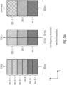
- Fig. 5a illustrates a first embodiment, where band-wise weighting values are calculated from two combined spectral domain representations where the two combined spectral domain representations both have a low frequency resolution and a low time resolution.
- Fig. 5c illustrates a further third embodiment, where a single combined representation is calculated and used for the calculation of the spectral domain band-wise weighting values using two spectral domain representations both having the low frequency resolution and the high time resolution.
- the weighting value estimator is configured to calculate the band-wise weighting values using two combined representations that are both in a format that shows the high frequency resolution and the high time resolution.
- Fig. 4a illustrates a situation, where there are two different resolutions (in time and/or frequency) in the first channel and the second channel.
- the first portion in Fig. 4a shows a frame having a long block in the first channel and two subsequent short blocks in the second channel.
- the long block can, for example, be a TCX20 block.
- the short blocks can be two subsequent TCX10 blocks.
- Fig. 4a illustrates a further frame which is subdivided into two sub-frames A, B, where, in the first channel, the sub-frame A has a short block and, in the second channel, the sub-frame has a short block as well.
- the first channel has a short block and the second channel has two very short blocks, i.e., one very short block for each sub-sub-frame.
- the very short block can, for example, be TCX5 blocks.
- the long blocks are longer than the short blocks and the short blocks are longer than the very short blocks and, of course, the very short blocks are shorter than the long blocks.
- Fig. 4b illustrates a representation of a spectrum with a high spectral resolution in the first line. Spectral values are indicated at integer numbers along the frequency line and Fig. 4b illustrates three subsequent bands b 1 , b 2 , b 3 , where each band representing higher frequencies is broader than each band representing lower frequencies.
- the lowest band b 1 has four spectral lines or spectral values or spectral bins.
- the second band b 2 has, in the embodiment, eight spectral values and the third spectral band b 3 has twelve spectral bins.
- Transferring or converting the high spectral resolution into a medium spectral resolution representation results in the fact that, from the high resolution spectral representation, spectral values are combined (or decimated) so that the medium spectral resolution such as a TCX10 resolution has two spectral bins for the first band, four spectral bins for the second band b 2 and six spectral bins for the third band b 3 .
- the medium spectral resolution such as a TCX10 resolution has two spectral bins for the first band, four spectral bins for the second band b 2 and six spectral bins for the third band b 3 .
- the medium spectral resolution could be converted into the low spectral resolution by combining two or more adjacent spectral lines or by a decimation operation.
- a low spectral resolution representation could be converted into a higher resolution representation by means of interpolation or copying or copying and filtering so that, for example, from the two spectral bins in the first band b 1 for the medium spectral resolution, four high resolution spectral bins 1, 2, 3, 4 as illustrated in Fig. 4b could be calculated.
- This novel approach aims at providing a delay-less, active, band-wise downmixing method for stereo-to-mono conversion where only the band-wise weighting of the spectral bands of the two channels is done in frequency domain while the actual downmix to a mono signal is done after transforming to time-domain by summing and scaling the two spectrally weighted signals.
- the weight calculation is adapted by combining neighboring spectral bins both temporally and spectrally so that the cross-spectra computation can be done on the same time-frequency regions.
- the time-frequency resolution of the two stereo channel does not need to be uniform as a band-wise weighting of channels can still be done if the channels differ in this regard while the critical stereo-to-mono conversion is done later when both spectrally weighted channels are already transformed back to time-domain.
- Embodiments provide an optimized, delay-less stereo-to-mono downmix at a decoder side.
- Preferred aspects relate to an active downmix with band-wise weighting with separated weighting (frequency-domain) and mixing stages (time-domain).
- Further preferred aspects relate to a temporal/spectral combination of frequency bins for cross-spectra correlation in case of channels with different spectral domain representations, where these aspects can be used separate from the downmix aspects or together with the downmix aspects.
- Fig. 3b illustrates a preferred implementation of the weighting value estimator 100 illustrated in Fig. 1 .
- the weighting value estimator estimates corresponding imaginary or real value spectral values per frequency bin from the first channel and the second channel or, alternatively, from the first channel and a combined spectral domain representation or from the second channel and the combined spectral domain representation or from a first combined spectral domain representation and a second combined spectral domain representation.
- the weighting value estimator is configured to calculate the first weighting value and the second weighting value using an energy of the first channel in the band, and energy of the second channel in the band and a mixed term depending on a product or a linear combination of spectral values from the at least two channels in the band.
- the energy of the first channel and the energy of the second channel is exemplarily calculated in block 140. Furthermore, a mixed term depending on a product is calculated in block 148 and another mixed term depending on a linear combination is calculated in block 146. Furthermore, an "amplitude" per band that corresponds to a square root of the power of the spectral bins per band is calculated in block 144.
- the first weighting value w L is calculated from the amplitudes per band for both channels and depending on a mixed term and, preferably, the mixed term depending on the linear combination illustrated in block 146. Furthermore, it is preferred that the weighting vector w L per band is calculated using the weighting value w R per band, i.e., for the other channel. The value for the other channel, i.e., w R per band is preferably calculated based on the mixed term depending on the product illustrated at 148 and the "amplitudes" per band derived by block 144 from the powers per band in the corresponding channels as determined in block 142.
- a square root of an energy of spectral values added to each other in the band from the spectral domain representations of the at least two channels is used as the "amplitudes", but other "amplitudes” can be used as well such as “amplitudes” derived from the powers by an exponent being lower than 1 and different from 1/2.
- the spectral values from a band are linearly combined, i.e., added to each other and a square root or any other exponentiation with an exponent lower than 1 of the resulting value is taken, where, preferably, the powers both for the channels in the band are additionally used.
- an absolute value of a complex dot product between the spectral values in the band of the first channel and the spectral values in the band of the second channel can be determined as well, for example, in the calculation of block 148.
- the same weight as determined by the spectral weighter 200 is applied to each spectral value in the band of one of the at least two channels and another weight is applied to each spectral value in the band of another channel of the at least two channels.
- band-wise weights are computed and applied to the MDCT representations of both channels. This happens after the Stereo processing (e.g. inverse MS etc.) and directly before the IMDCT back transform.
- weights or band-wise weighting values w R and w L are computed per spectral band with each band encompassing several MDCT bins starting with a low number of bins for the lowest bands e.g. 4 and increasing towards higher frequencies up to several or many bins for the highest band e.g. 160.
- L + R L 2 + R 2 + 2 ⁇ i in b MDCT i , l MDCT i , r + MDST i , l MDST i , r 2 and
- the two weighted channels are then downmixed in time domain by simple summing and scaling of the two spectrally weighted channels.
- MDCT Stereo is configured to allow different core coder and/or overlap decisions for the two channels. Concretely, this means that one channel can be coded with e.g. one TCX20 long block (20ms frame, higher frequency resolution, lower time resolution) while the other is coded with e.g.
- Fig. 5a works as follows: For the special case of different cores in the two channels the computation of the cross-spectra correlation as part of the weight calculation has to be slightly adapted. Due to the different frequency and time resolutions of TCX20 and TCX10, directly calculating the dot product between left and right is not possible . Instead, the MDCT bins have to be combined so that they cover the same time-frequency regions.
- FIG. 5b Another embodiment illustrated in Fig. 5b works as follows: For the special case of different cores in the two channels the computation of the cross-spectra correlation as part of the weight calculation has to be slightly adapted. Due to the different frequency and time resolutions of TCX20 and TCX10, directly calculating the dot product between left and right is not possible.
- the MDST estimates and the final channel weights are then computed using these converted spectra.
- the weights themselves are applied to the original input spectra which means that in case of a conversion each computed weight is applied to all bins covering the same frequency range in the original lower resolution for every subframe.
- the new method is able to output a mono signal with the advantages of the active downmix, but without additional delay or complexity and independent of the chosen time-frequency resolution of the individual channels.
- time domain post processing e.g. TCX-LTP post-filter using pitch information
- Fig. 5a illustrates the first alternative, where two combined spectral domain representations are generated.
- the first combined spectral domain representation is calculated by adding two neighboring bins of the high resolution spectral domain representation illustrated to the left of Fig. 5a to obtain the first combined spectral domain representation.
- the weighting value estimator 100 is configured to calculate the left and the right weighting factors w L and w R from these two combined spectral domain representations.
- the weighting factor for the left channel is applied to the original left channel representation, i.e., the TCX20 representation illustrated to the left of Fig. 5a .
- the band-wise weighting values for the right channel represented by two time-subsequent TCX10 blocks are applied to both TCX10 blocks.
- the same band-wise weighting value is applied to the corresponding bands of the two time-subsequent TCX10 blocks illustrated in the middle of Fig. 5a .
- a single combined spectral domain representation is calculated as illustrated for several different cases.
- a sub-frame in the first channel has two very short such as TCX5 frames and the next sub-frame has a single TCX10 frame
- the second channel has, for example, two TCX10 frames
- the combined spectral domain representation is calculated for the first sub-sub-frame while, for the second sub-sub-frame, the first and the second channel already are in the TCX10 representation.
- the spectral weighter 200 is configured to apply the high spectral resolution weighting factors to corresponding bands in the sub-frames each representing five milliseconds, for example. Furthermore, the high resolution weighting factors are applied to corresponding original spectral domain representations of the other channel having a short TCX10 frame in the first sub-frame A, for example.
- the situation is so that the first channel has a representation illustrated to the left of Fig. 5b and the second channel has a representation illustrated to the right of Fig. 5b , the representation of the first channel is converted into a single combined spectral domain representation via the two steps from the left in Fig. 5b to the middle and from the middle in Fig. 5b to the right.
- the frequency resolution is used for calculating the weighting factors and the corresponding weighting factors are applied to the high frequency resolution and low time resolution representation of the second channel that would have a resolution illustrated to the right in Fig. 5b , and the same values for a band would be applied to all the individual sub-frames A, B and the next sub-frame illustrated by D and C in Fig. 5b .
- Fig. 5c illustrates another alternative where the actual domain weighting values are calculated from a low frequency resolution and a high time resolution representation.
- the first channel is, for example, a TCX20 representation and the second channel is, for example, a sequence of two TCX10 representations.
- the combined representation is now a high time resolution and low frequency resolution representation illustrated in the upper right corner of Fig. 5c .
- the spectral domain weighting factors are calculated from the combined representation on the one hand and the original spectral domain representation of the second channel illustrated in the lower left corner of Fig. 5c .
- Two sets of band-wise weighting values are obtained, i.e., one for each sub-frame. These values are applied to the corresponding sub-frames of the second channel.
- derived spectral domain weighting values are calculated as illustrated at block 136 in Fig. 3a .
- One procedure for calculating a derived spectral domain weighting value is to perform a weighted addition of the corresponding weighting values of one and the same band for the two (or more) sub-frames, wherein each weighting value is, for example, weighted by means of 0.5 in the weighted addition resulting in an averaging operation.
- Another alternative would be to calculate an arithmetic or geometric mean of the weighting values for the two sub-frames or any other procedure to obtain a single weighting value from two weighting values for a band in a frame.
- An option could be simply to select one of the two values and to neglect the other one, etc.
- a procedure as discussed before with respect to Fig. 5a can be used, i.e., two neighboring spectral values can be added together to reduce the spectral resolution.
- Fig. 5d illustrates a further implementation where the first channel has a high frequency and low time resolution representation such as a TCX20 representation, and the second channel has a low frequency and high time resolution representation such as a sequence of two short frames such as two TCX10 frames.
- the first combined spectral domain representation is a high frequency resolution and high time resolution representation and the second combined spectral domain representation is, additionally, a high frequency resolution and a high time resolution.
- the procedure illustrated in Fig. 5d can, for example, be performed in such a way that, from the first channel, the first combined spectral domain representation is calculated by taking the same spectral values, but now for two subsequent time frames illustrated by TCX10.
- some kind of interpolation processing, etc. can be performed as well in order to double the number of frames so that, from a TCX20 frame, two subsequent TCX10 frames are calculated. Furthermore, the second channel is already in the correct time resolution but the frequency resolution has to be doubled. To this end, a procedure from a lower line to a higher line in Fig. 4b can be performed, i.e., the spectral value in a frequency bin of TCX10 representation can be processed to have the same spectral value for a pair of frequency bins. In order to have correct energy, some kind of weighting can be performed.
- spectral domain weighting values are calculated by the weighting value estimator 100 from the first combined spectral domain representation and the second combined spectral domain representation that are derived from high frequency resolution and high time resolution data.
- the spectral weighter 200 is configured to apply the corresponding spectral domain weighting values to the second channel where for each sub-frame a set of band-wise weighting values exists.
- the weighting value estimator 100 is configured to once again calculate derived bandwise weighting factors 136, since only one set of spectral domain weighting factors is required for weighting the first channel high frequency resolution and time resolution (TCX20) spectral domain representation.
- a combination procedure to calculate the derived band-wise weighting values could be an averaging, for example.
- Fig. 6 illustrates a further aspect of the invention, i.e., an apparatus for converting a spectral resolution of a spectral domain representation of a channel comprising at least two sub-frames, wherein each sub-frame comprises a plurality of spectral values representing a time bin size and a frequency bin size.
- the spectral value calculator 160 included in the apparatus for converting, in accordance with the second aspect, comprises a first manner combiner 170 and a second manner combiner 180.
- the first manner combiner operates as a low pass processor and the second manner combiner operates a high pass processor.
- the spectral value calculator combines, by means of the first manner combiner, spectral values belonging to the same frequency bin from each sub-frame of the spectral domain representation to obtain a first group of combined spectral values and the second manner combiner 180 combines spectral values belonging to the same frequency bin from each sub-frame of the spectral domain representation in a second manner to obtain a second group of combined spectral values, where the second manner is different from the first manner and where the first group of combined spectral values and the second group of combined spectral values represent a combined spectral domain representation having a different time bin size and a different frequency bin size.
- a preferred implementation of this calculation is described and illustrated with respect to Fig.
- Fig. 5b also illustrates the situation where the at least two sub-frames are illustrated in the middle chart of Fig. 5b as being two time-subsequent 10 ms sub-frames and where the high spectral resolution and low time resolution representation is illustrated to the right of Fig. 5b .
- an addition is performed in the first manner and a subtraction is performed in the second manner.
- both procedures also comprise an average function.
- the spectral value calculator 160 in Fig. 6 is configured to apply either the first manner or the second manner comprising a weighting using a weighting sign, where the spectral value calculator is configured to set the weighting sign in accordance with a frequency bin number of the same frequency bin.
- the spectral value calculator is, as illustrated in Fig. 5b , configured to transform a lower resolution bin into two higher resolution bins where the first manner is used for an even bin number and the second manner is used for an odd bin number.
- Fig. 7 illustrates a further implementation of the apparatus for converting a spectral resolution.
- the apparatus for converting a spectral resolution may comprise further elements.
- the further elements are, for example, a spectral processor 500 and/or a processing data calculator 190 and/or a further spectral processor 220.
- the converted spectral domain representation that has been converted without any inverse and forward transform operations and, therefore, has been generated with low computational resources and low delay can be further processed alone or, for example, together with another spectral representation that has the same second spectral resolution. This can, for example, be performed for some kind of downmixing.
- the high frequency resolution low time resolution representation illustrated to the right of Fig. 5b can not only be used for calculating processing data but is actually further processed for additional or other alternative usage such as, for example, downmixing or any kind of audio rendering in a later processing stage.
- the procedure discussed before with respect to Fig. 1 and Fig. 5b is that the spectral domain representation with the second spectral resolution, i.e., the "combined spectral domain representation" is just used for calculating some kind of processing data such as weighting values for a left and a right channel or, stated generally, for a first and a second channel of a multi-channel signal.
- the processing data generated using the spectral domain representation that has been converted into a high spectral resolution is only used for calculating processing data but this spectral domain representation is not further processed by itself. Instead, using the processing data such as the weighting values, the original input spectral domain representation with the first spectral resolution is spectrally processed as illustrated by block 220.
- Fig. 8 illustrates an embodiment of a third aspect of the present invention operating as a downmixer for downmixing a multi-channel signal having at least two channels.
- the downmixer comprises a weighting value estimator 100 for estimating band-wise weighting values for the at least two channels, where the weighting value estimator is configured to calculate the band-wise weighting values based on the target energy value per band, so that an energy in the band of a downmix signal is in a predetermined relation to energies in the same bands of the at two channels.
- the weighting value estimator 100 is implemented as illustrated in Fig. 3b and as discussed in the context of Fig. 3b .
- the downmixer additionally comprises a spectral weighter 200 and a subsequently connected mixer 400 for calculating the downmix signal using the weighted spectral domain representations of the at least two channels.
- Fig. 9 illustrates a further implementation of the Fig. 8 downmixer.
- the spectral weighter 200 is preferably configured to receive control data for the first and/or the second channel. Furthermore, the spectral weighter is configured to apply the control data for one of four different pairs of input data.
- the first pair of input data can be the first channel spectral domain representation and the second channel spectral domain representation as illustrated to the left in Fig. 9 .
- the second alternative can be the first channel spectral domain representation and the combined spectral domain representation derived as, for example, discussed with respect to Fig. 5b , 5c .
- the other alternative can be a pair of data representing the second channel spectral domain representation and a single combined spectral domain representation as also discussed before with respect to Fig.
- the control data for the first and/or second channels can, for example, be the weighting values w L on the one hand and w R on the other hand, but can also be any other control data used for performing any kind of spectral weighting.
- a further element of the downmixer is, in an embodiment, an adder 480 that calculates an added spectral domain representation, i.e., a downmix spectral domain representation in the spectral domain.
- a mono signal processor 490 can be used that is, for example, controlled by any data or that is, for example, implemented as a frequency-time converter as has been discussed before with respect to block 310 of Fig. 1 or Fig. 2 .
- the three aspects can be used separately from each other but can also be advantageously combined to each other.
- the implementation of the weighting value estimator in accordance with Fig. 8 can be applied in the weighting value estimator 100 of the first aspect illustrated in Fig. 1 .
- the spectral resolution converter illustrated in Fig. 6 is preferably implemented by the weighting value estimator 100 of Fig. 1 in the alternative illustrated in Fig. 5b generating a high resolution/low resolution spectral domain representation from two high time resolution and low spectral resolution sub-frames.
- the three aspects can be applied separately or can be combined to each other either by combining any two of the three aspects or by combining all three aspects.
- An inventively encoded audio signal can be stored on a digital storage medium or a non-transitory storage medium or can be transmitted on a transmission medium such as a wireless transmission medium or a wired transmission medium such as the Internet.
- aspects have been described in the context of an apparatus, it is clear that these aspects also represent a description of the corresponding method, where a block or device corresponds to a method step or a feature of a method step. Analogously, aspects described in the context of a method step also represent a description of a corresponding block or item or feature of a corresponding apparatus.
- embodiments of the invention can be implemented in hardware or in software.
- the implementation can be performed using a digital storage medium, for example a floppy disk, a DVD, a CD, a ROM, a PROM, an EPROM, an EEPROM or a FLASH memory, having electronically readable control signals stored thereon, which cooperate (or are capable of cooperating) with a programmable computer system such that the respective method is performed.
- a digital storage medium for example a floppy disk, a DVD, a CD, a ROM, a PROM, an EPROM, an EEPROM or a FLASH memory, having electronically readable control signals stored thereon, which cooperate (or are capable of cooperating) with a programmable computer system such that the respective method is performed.
- Some embodiments according to the invention comprise a data carrier having electronically readable control signals, which are capable of cooperating with a programmable computer system, such that one of the methods described herein is performed.
- embodiments of the present invention can be implemented as a computer program product with a program code, the program code being operative for performing one of the methods when the computer program product runs on a computer.
- the program code may for example be stored on a machine readable carrier.
- inventions comprise the computer program for performing one of the methods described herein, stored on a machine readable carrier or a non-transitory storage medium.
- an embodiment of the inventive method is, therefore, a computer program having a program code for performing one of the methods described herein, when the computer program runs on a computer.
- a further embodiment of the inventive methods is, therefore, a data carrier (or a digital storage medium, or a computer-readable medium) comprising, recorded thereon, the computer program for performing one of the methods described herein.
- a further embodiment of the inventive method is, therefore, a data stream or a sequence of signals representing the computer program for performing one of the methods described herein.
- the data stream or the sequence of signals may for example be configured to be transferred via a data communication connection, for example via the Internet.
- a further embodiment comprises a processing means, for example a computer, or a programmable logic device, configured to or adapted to perform one of the methods described herein.
- a processing means for example a computer, or a programmable logic device, configured to or adapted to perform one of the methods described herein.
- a further embodiment comprises a computer having installed thereon the computer program for performing one of the methods described herein.
- a programmable logic device for example a field programmable gate array
- a field programmable gate array may cooperate with a microprocessor in order to perform one of the methods described herein.
- the methods are preferably performed by any hardware apparatus.
Landscapes
- Engineering & Computer Science (AREA)
- Physics & Mathematics (AREA)
- Acoustics & Sound (AREA)
- Signal Processing (AREA)
- Multimedia (AREA)
- Computational Linguistics (AREA)
- Health & Medical Sciences (AREA)
- Audiology, Speech & Language Pathology (AREA)
- Human Computer Interaction (AREA)
- Mathematical Physics (AREA)
- Spectroscopy & Molecular Physics (AREA)
- Theoretical Computer Science (AREA)
- General Physics & Mathematics (AREA)
- Mathematical Analysis (AREA)
- Mathematical Optimization (AREA)
- Pure & Applied Mathematics (AREA)
- Algebra (AREA)
- Stereophonic System (AREA)
- Complex Calculations (AREA)
- Superheterodyne Receivers (AREA)
- Stereo-Broadcasting Methods (AREA)
- Compression, Expansion, Code Conversion, And Decoders (AREA)
- Amplifiers (AREA)
Applications Claiming Priority (3)
| Application Number | Priority Date | Filing Date | Title |
|---|---|---|---|
| EP19161076 | 2019-03-06 | ||
| EP20706774.5A EP3935630B1 (de) | 2019-03-06 | 2020-03-04 | Abwärtsmischung von audiosignales |
| PCT/EP2020/055669 WO2020178321A1 (en) | 2019-03-06 | 2020-03-04 | Downmixer and method of downmixing |
Related Parent Applications (1)
| Application Number | Title | Priority Date | Filing Date |
|---|---|---|---|
| EP20706774.5A Division EP3935630B1 (de) | 2019-03-06 | 2020-03-04 | Abwärtsmischung von audiosignales |
Publications (4)
| Publication Number | Publication Date |
|---|---|
| EP4447043A2 true EP4447043A2 (de) | 2024-10-16 |
| EP4447043A3 EP4447043A3 (de) | 2024-11-27 |
| EP4447043C0 EP4447043C0 (de) | 2025-12-03 |
| EP4447043B1 EP4447043B1 (de) | 2025-12-03 |
Family
ID=65801834
Family Applications (2)
| Application Number | Title | Priority Date | Filing Date |
|---|---|---|---|
| EP24197969.9A Active EP4447043B1 (de) | 2019-03-06 | 2020-03-04 | Audioabwärtsmischung |
| EP20706774.5A Active EP3935630B1 (de) | 2019-03-06 | 2020-03-04 | Abwärtsmischung von audiosignales |
Family Applications After (1)
| Application Number | Title | Priority Date | Filing Date |
|---|---|---|---|
| EP20706774.5A Active EP3935630B1 (de) | 2019-03-06 | 2020-03-04 | Abwärtsmischung von audiosignales |
Country Status (15)
| Country | Link |
|---|---|
| US (2) | US12230281B2 (de) |
| EP (2) | EP4447043B1 (de) |
| JP (3) | JP7416816B2 (de) |
| KR (1) | KR102847181B1 (de) |
| CN (2) | CN119007734A (de) |
| AU (2) | AU2020233210B2 (de) |
| BR (1) | BR112021017197A2 (de) |
| ES (1) | ES2989883T3 (de) |
| MX (1) | MX2021010570A (de) |
| MY (1) | MY209301A (de) |
| PL (1) | PL3935630T3 (de) |
| SG (1) | SG11202108895TA (de) |
| TW (2) | TW202042214A (de) |
| WO (2) | WO2020178322A1 (de) |
| ZA (1) | ZA202107327B (de) |
Families Citing this family (1)
| Publication number | Priority date | Publication date | Assignee | Title |
|---|---|---|---|---|
| GB2630636A (en) * | 2023-06-01 | 2024-12-04 | Nokia Technologies Oy | Apparatus, methods and computer program for selecting a mode for an input format of an audio stream |
Citations (2)
| Publication number | Priority date | Publication date | Assignee | Title |
|---|---|---|---|---|
| US20120014526A1 (en) | 2008-11-11 | 2012-01-19 | Institut Fur Rundfunktechnik Gmbh | Method for Generating a Downward-Compatible Sound Format |
| US20160037279A1 (en) | 2014-08-01 | 2016-02-04 | Steven Jay Borne | Audio Device |
Family Cites Families (23)
| Publication number | Priority date | Publication date | Assignee | Title |
|---|---|---|---|---|
| EP1611772A1 (de) | 2003-03-04 | 2006-01-04 | Nokia Corporation | Träger für eine mehrkanalaudioerweiterung |
| KR101035104B1 (ko) * | 2003-03-17 | 2011-05-19 | 코닌클리케 필립스 일렉트로닉스 엔.브이. | 다중-채널 신호들의 처리 |
| US7447317B2 (en) * | 2003-10-02 | 2008-11-04 | Fraunhofer-Gesellschaft Zur Foerderung Der Angewandten Forschung E.V | Compatible multi-channel coding/decoding by weighting the downmix channel |
| ATE475964T1 (de) | 2004-03-01 | 2010-08-15 | Dolby Lab Licensing Corp | Mehrkanal-audiodekodierung |
| TW200742275A (en) | 2006-03-21 | 2007-11-01 | Dolby Lab Licensing Corp | Low bit rate audio encoding and decoding in which multiple channels are represented by fewer channels and auxiliary information |
| BRPI0709310B1 (pt) * | 2006-10-25 | 2019-11-05 | Fraunhofer Ges Zur Foeerderung Der Angewandten Forschung E V | equipamento e método para a geração de valores de sub-banda de áudio e equipamento e método para a geração de amostras de áudio no domínio do tempo |
| KR20080076691A (ko) * | 2007-02-14 | 2008-08-20 | 엘지전자 주식회사 | 멀티채널 오디오신호 복호화방법 및 그 장치, 부호화방법및 그 장치 |
| JP5058844B2 (ja) | 2008-02-18 | 2012-10-24 | シャープ株式会社 | 音声信号変換装置、音声信号変換方法、制御プログラム、および、コンピュータ読み取り可能な記録媒体 |
| JP5243527B2 (ja) * | 2008-07-29 | 2013-07-24 | パナソニック株式会社 | 音響符号化装置、音響復号化装置、音響符号化復号化装置および会議システム |
| EP2237266A1 (de) * | 2009-04-03 | 2010-10-06 | Fraunhofer-Gesellschaft zur Förderung der angewandten Forschung e.V. | Vorrichtung und Verfahren zur Bestimmung mehrerer lokaler Schwerpunktsfrequenzen eines Audiosignalspektrums |
| EP2323130A1 (de) | 2009-11-12 | 2011-05-18 | Koninklijke Philips Electronics N.V. | Parametrische Kodierung- und Dekodierung |
| KR101756838B1 (ko) * | 2010-10-13 | 2017-07-11 | 삼성전자주식회사 | 다채널 오디오 신호를 다운 믹스하는 방법 및 장치 |
| CN103959375B (zh) * | 2011-11-30 | 2016-11-09 | 杜比国际公司 | 增强的从音频编解码器的色度提取 |
| KR20150032614A (ko) * | 2012-06-04 | 2015-03-27 | 삼성전자주식회사 | 오디오 부호화방법 및 장치, 오디오 복호화방법 및 장치, 및 이를 채용하는 멀티미디어 기기 |
| EP2738762A1 (de) | 2012-11-30 | 2014-06-04 | Aalto-Korkeakoulusäätiö | Verfahren zur Raumfilterung von mindestens einem ersten Tonsignal, computerlesbares Speichermedium und Raumfilterungssystem basierend auf Kreuzmuster-Kohärenz |
| TWI618051B (zh) * | 2013-02-14 | 2018-03-11 | 杜比實驗室特許公司 | 用於利用估計之空間參數的音頻訊號增強的音頻訊號處理方法及裝置 |
| EP2790419A1 (de) | 2013-04-12 | 2014-10-15 | Fraunhofer-Gesellschaft zur Förderung der angewandten Forschung e.V. | Vorrichtung und Verfahren zur Mittelsignalskalierung und stereophone Verbesserung auf Basis eines Signal-to-Downmix-Verhältnisses |
| KR20160072131A (ko) | 2013-10-02 | 2016-06-22 | 슈트로밍스위스 게엠베하 | 다채널 신호의 다운믹스 및 다운믹스 신호의 업믹스 방법 및 장치 |
| US10217467B2 (en) * | 2016-06-20 | 2019-02-26 | Qualcomm Incorporated | Encoding and decoding of interchannel phase differences between audio signals |
| RU2725178C1 (ru) | 2016-11-08 | 2020-06-30 | Фраунхофер-Гезелльшафт Цур Фердерунг Дер Ангевандтен Форшунг Е.Ф. | Устройство и способ для кодирования или декодирования многоканального сигнала с использованием коэффициента передачи побочного сигнала и коэффициента передачи остаточного сигнала |
| ES3042934T3 (en) | 2016-11-08 | 2025-11-24 | Fraunhofer Ges Forschung | Downmixer and method for downmixing at least two channels and multichannel encoder and multichannel decoder |
| JP2017058696A (ja) * | 2016-12-09 | 2017-03-23 | ホアウェイ・テクノロジーズ・カンパニー・リミテッド | インターチャネル差分推定方法及び空間オーディオ符号化装置 |
| GB2561596A (en) * | 2017-04-20 | 2018-10-24 | Nokia Technologies Oy | Audio signal generation for spatial audio mixing |
-
2020
- 2020-03-04 AU AU2020233210A patent/AU2020233210B2/en active Active
- 2020-03-04 CN CN202411066245.4A patent/CN119007734A/zh active Pending
- 2020-03-04 WO PCT/EP2020/055671 patent/WO2020178322A1/en not_active Ceased
- 2020-03-04 WO PCT/EP2020/055669 patent/WO2020178321A1/en not_active Ceased
- 2020-03-04 JP JP2021550157A patent/JP7416816B2/ja active Active
- 2020-03-04 KR KR1020217032037A patent/KR102847181B1/ko active Active
- 2020-03-04 EP EP24197969.9A patent/EP4447043B1/de active Active
- 2020-03-04 CN CN202080019078.1A patent/CN113544774B/zh active Active
- 2020-03-04 BR BR112021017197A patent/BR112021017197A2/pt unknown
- 2020-03-04 PL PL20706774.5T patent/PL3935630T3/pl unknown
- 2020-03-04 SG SG11202108895TA patent/SG11202108895TA/en unknown
- 2020-03-04 MX MX2021010570A patent/MX2021010570A/es unknown
- 2020-03-04 MY MYPI2021005080A patent/MY209301A/en unknown
- 2020-03-04 EP EP20706774.5A patent/EP3935630B1/de active Active
- 2020-03-04 ES ES20706774T patent/ES2989883T3/es active Active
- 2020-03-05 TW TW109107331A patent/TW202042214A/zh unknown
- 2020-03-05 TW TW109107332A patent/TWI760705B/zh active
-
2021
- 2021-08-12 US US17/400,872 patent/US12230281B2/en active Active
- 2021-09-29 ZA ZA2021/07327A patent/ZA202107327B/en unknown
-
2023
- 2023-11-01 AU AU2023258388A patent/AU2023258388A1/en not_active Abandoned
- 2023-11-02 JP JP2023188061A patent/JP2024001324A/ja not_active Ceased
- 2023-11-02 JP JP2023188062A patent/JP2024001325A/ja not_active Ceased
-
2025
- 2025-01-13 US US19/018,462 patent/US20250149047A1/en active Pending
Patent Citations (2)
| Publication number | Priority date | Publication date | Assignee | Title |
|---|---|---|---|---|
| US20120014526A1 (en) | 2008-11-11 | 2012-01-19 | Institut Fur Rundfunktechnik Gmbh | Method for Generating a Downward-Compatible Sound Format |
| US20160037279A1 (en) | 2014-08-01 | 2016-02-04 | Steven Jay Borne | Audio Device |
Non-Patent Citations (3)
| Title |
|---|
| A. ADAMI, E. HABETS AND J. HERRE: "International Conference on Acoustics, Speech and Signal Processing", 2014, CONVENTION OF THE AES, |
| G. STOLLJ. GROHM. LINKJ. DEIGMÖLLERB. RUNOWM. KEILR. STOLLM. STOLLC. STOLL, METHOD FOR GENERATING A DOWNWARD-COMPATIBLE SOUND FORMAT |
| S. CHENH. RUIMINS. ZHANG: "Estimating spatial cues for audio coding in MDCT domain", IEEE INTERNATIONAL CONFERENCE ON MULTIMEDIA AND EXPO, 2009 |
Also Published As
Similar Documents
| Publication | Publication Date | Title |
|---|---|---|
| US12236960B2 (en) | Apparatus, method and computer program for upmixing a downmix audio signal using a phase value smoothing | |
| RU2639952C2 (ru) | Гибридное усиление речи с кодированием формы сигнала и параметрическим кодированием | |
| US20120033817A1 (en) | Method and apparatus for estimating a parameter for low bit rate stereo transmission | |
| US20250166654A1 (en) | Apparatus, method or computer program for generating an output downmix representation | |
| US20250149047A1 (en) | Downmixer and Method of Downmixing | |
| HK40060438B (en) | Audio downmixing | |
| HK40060438A (en) | Audio downmixing | |
| CA3132404C (en) | Downmixer and method of downmixing | |
| RU2791673C1 (ru) | Устройство понижающего микширования и способ понижающего микширования |
Legal Events
| Date | Code | Title | Description |
|---|---|---|---|
| PUAI | Public reference made under article 153(3) epc to a published international application that has entered the european phase |
Free format text: ORIGINAL CODE: 0009012 |
|
| STAA | Information on the status of an ep patent application or granted ep patent |
Free format text: STATUS: THE APPLICATION HAS BEEN PUBLISHED |
|
| AC | Divisional application: reference to earlier application |
Ref document number: 3935630 Country of ref document: EP Kind code of ref document: P |
|
| AK | Designated contracting states |
Kind code of ref document: A2 Designated state(s): AL AT BE BG CH CY CZ DE DK EE ES FI FR GB GR HR HU IE IS IT LI LT LU LV MC MK MT NL NO PL PT RO RS SE SI SK SM TR |
|
| REG | Reference to a national code |
Ref country code: DE Ref legal event code: R079 Free format text: PREVIOUS MAIN CLASS: G10L0019020000 Ipc: G10L0019008000 Ref country code: DE Ref legal event code: R079 Ref document number: 602020063524 Country of ref document: DE Free format text: PREVIOUS MAIN CLASS: G10L0019020000 Ipc: G10L0019008000 |
|
| PUAL | Search report despatched |
Free format text: ORIGINAL CODE: 0009013 |
|
| AK | Designated contracting states |
Kind code of ref document: A3 Designated state(s): AL AT BE BG CH CY CZ DE DK EE ES FI FR GB GR HR HU IE IS IT LI LT LU LV MC MK MT NL NO PL PT RO RS SE SI SK SM TR |
|
| RIC1 | Information provided on ipc code assigned before grant |
Ipc: G10L 19/02 20130101ALN20241024BHEP Ipc: H03G 5/16 20060101ALN20241024BHEP Ipc: H04S 3/02 20060101ALN20241024BHEP Ipc: G10L 19/008 20130101AFI20241024BHEP |
|
| STAA | Information on the status of an ep patent application or granted ep patent |
Free format text: STATUS: REQUEST FOR EXAMINATION WAS MADE |
|
| GRAP | Despatch of communication of intention to grant a patent |
Free format text: ORIGINAL CODE: EPIDOSNIGR1 |
|
| STAA | Information on the status of an ep patent application or granted ep patent |
Free format text: STATUS: GRANT OF PATENT IS INTENDED |
|
| 17P | Request for examination filed |
Effective date: 20250527 |
|
| RIC1 | Information provided on ipc code assigned before grant |
Ipc: G10L 19/008 20130101AFI20250613BHEP Ipc: H04S 3/02 20060101ALN20250613BHEP Ipc: H03G 5/16 20060101ALN20250613BHEP Ipc: G10L 19/02 20130101ALN20250613BHEP |
|
| INTG | Intention to grant announced |
Effective date: 20250630 |
|
| RIC1 | Information provided on ipc code assigned before grant |
Ipc: G10L 19/008 20130101AFI20250623BHEP Ipc: H04S 3/02 20060101ALN20250623BHEP Ipc: H03G 5/16 20060101ALN20250623BHEP Ipc: G10L 19/02 20130101ALN20250623BHEP |
|
| GRAS | Grant fee paid |
Free format text: ORIGINAL CODE: EPIDOSNIGR3 |
|
| GRAA | (expected) grant |
Free format text: ORIGINAL CODE: 0009210 |
|
| STAA | Information on the status of an ep patent application or granted ep patent |
Free format text: STATUS: THE PATENT HAS BEEN GRANTED |
|
| AC | Divisional application: reference to earlier application |
Ref document number: 3935630 Country of ref document: EP Kind code of ref document: P |
|
| AK | Designated contracting states |
Kind code of ref document: B1 Designated state(s): AL AT BE BG CH CY CZ DE DK EE ES FI FR GB GR HR HU IE IS IT LI LT LU LV MC MK MT NL NO PL PT RO RS SE SI SK SM TR |
|
| REG | Reference to a national code |
Ref country code: CH Ref legal event code: F10 Free format text: ST27 STATUS EVENT CODE: U-0-0-F10-F00 (AS PROVIDED BY THE NATIONAL OFFICE) Effective date: 20251203 Ref country code: GB Ref legal event code: FG4D |
|
| REG | Reference to a national code |
Ref country code: DE Ref legal event code: R096 Ref document number: 602020063524 Country of ref document: DE |
|
| REG | Reference to a national code |
Ref country code: IE Ref legal event code: FG4D |
|
| U01 | Request for unitary effect filed |
Effective date: 20251215 |
|
| U07 | Unitary effect registered |
Designated state(s): AT BE BG DE DK EE FI FR IT LT LU LV MT NL PT RO SE SI Effective date: 20251219 |