EP4446495A1 - Control method and apparatus for clothes drying device, clothes drying device and storage medium - Google Patents
Control method and apparatus for clothes drying device, clothes drying device and storage medium Download PDFInfo
- Publication number
- EP4446495A1 EP4446495A1 EP22903133.1A EP22903133A EP4446495A1 EP 4446495 A1 EP4446495 A1 EP 4446495A1 EP 22903133 A EP22903133 A EP 22903133A EP 4446495 A1 EP4446495 A1 EP 4446495A1
- Authority
- EP
- European Patent Office
- Prior art keywords
- clothes
- rotation speed
- drum
- fan
- speed value
- Prior art date
- Legal status (The legal status is an assumption and is not a legal conclusion. Google has not performed a legal analysis and makes no representation as to the accuracy of the status listed.)
- Pending
Links
Images

Classifications
-
- D—TEXTILES; PAPER
- D06—TREATMENT OF TEXTILES OR THE LIKE; LAUNDERING; FLEXIBLE MATERIALS NOT OTHERWISE PROVIDED FOR
- D06F—LAUNDERING, DRYING, IRONING, PRESSING OR FOLDING TEXTILE ARTICLES
- D06F58/00—Domestic laundry dryers
- D06F58/32—Control of operations performed in domestic laundry dryers
- D06F58/34—Control of operations performed in domestic laundry dryers characterised by the purpose or target of the control
- D06F58/36—Control of operational steps, e.g. for optimisation or improvement of operational steps depending on the condition of the laundry
- D06F58/38—Control of operational steps, e.g. for optimisation or improvement of operational steps depending on the condition of the laundry of drying, e.g. to achieve the target humidity
-
- D—TEXTILES; PAPER
- D06—TREATMENT OF TEXTILES OR THE LIKE; LAUNDERING; FLEXIBLE MATERIALS NOT OTHERWISE PROVIDED FOR
- D06F—LAUNDERING, DRYING, IRONING, PRESSING OR FOLDING TEXTILE ARTICLES
- D06F34/00—Details of control systems for washing machines, washer-dryers or laundry dryers
- D06F34/04—Signal transfer or data transmission arrangements
-
- D—TEXTILES; PAPER
- D06—TREATMENT OF TEXTILES OR THE LIKE; LAUNDERING; FLEXIBLE MATERIALS NOT OTHERWISE PROVIDED FOR
- D06F—LAUNDERING, DRYING, IRONING, PRESSING OR FOLDING TEXTILE ARTICLES
- D06F58/00—Domestic laundry dryers
- D06F58/02—Domestic laundry dryers having dryer drums rotating about a horizontal axis
- D06F58/04—Details
- D06F58/08—Driving arrangements
-
- D—TEXTILES; PAPER
- D06—TREATMENT OF TEXTILES OR THE LIKE; LAUNDERING; FLEXIBLE MATERIALS NOT OTHERWISE PROVIDED FOR
- D06F—LAUNDERING, DRYING, IRONING, PRESSING OR FOLDING TEXTILE ARTICLES
- D06F2103/00—Parameters monitored or detected for the control of domestic laundry washing machines, washer-dryers or laundry dryers
- D06F2103/02—Characteristics of laundry or load
- D06F2103/04—Quantity, e.g. weight or variation of weight
-
- D—TEXTILES; PAPER
- D06—TREATMENT OF TEXTILES OR THE LIKE; LAUNDERING; FLEXIBLE MATERIALS NOT OTHERWISE PROVIDED FOR
- D06F—LAUNDERING, DRYING, IRONING, PRESSING OR FOLDING TEXTILE ARTICLES
- D06F2103/00—Parameters monitored or detected for the control of domestic laundry washing machines, washer-dryers or laundry dryers
- D06F2103/28—Air properties
- D06F2103/32—Temperature
-
- D—TEXTILES; PAPER
- D06—TREATMENT OF TEXTILES OR THE LIKE; LAUNDERING; FLEXIBLE MATERIALS NOT OTHERWISE PROVIDED FOR
- D06F—LAUNDERING, DRYING, IRONING, PRESSING OR FOLDING TEXTILE ARTICLES
- D06F2105/00—Systems or parameters controlled or affected by the control systems of washing machines, washer-dryers or laundry dryers
- D06F2105/28—Electric heating
-
- D—TEXTILES; PAPER
- D06—TREATMENT OF TEXTILES OR THE LIKE; LAUNDERING; FLEXIBLE MATERIALS NOT OTHERWISE PROVIDED FOR
- D06F—LAUNDERING, DRYING, IRONING, PRESSING OR FOLDING TEXTILE ARTICLES
- D06F2105/00—Systems or parameters controlled or affected by the control systems of washing machines, washer-dryers or laundry dryers
- D06F2105/30—Blowers
-
- D—TEXTILES; PAPER
- D06—TREATMENT OF TEXTILES OR THE LIKE; LAUNDERING; FLEXIBLE MATERIALS NOT OTHERWISE PROVIDED FOR
- D06F—LAUNDERING, DRYING, IRONING, PRESSING OR FOLDING TEXTILE ARTICLES
- D06F2105/00—Systems or parameters controlled or affected by the control systems of washing machines, washer-dryers or laundry dryers
- D06F2105/32—Air flow control means
-
- D—TEXTILES; PAPER
- D06—TREATMENT OF TEXTILES OR THE LIKE; LAUNDERING; FLEXIBLE MATERIALS NOT OTHERWISE PROVIDED FOR
- D06F—LAUNDERING, DRYING, IRONING, PRESSING OR FOLDING TEXTILE ARTICLES
- D06F2105/00—Systems or parameters controlled or affected by the control systems of washing machines, washer-dryers or laundry dryers
- D06F2105/46—Drum speed; Actuation of motors, e.g. starting or interrupting
- D06F2105/48—Drum speed
-
- D—TEXTILES; PAPER
- D06—TREATMENT OF TEXTILES OR THE LIKE; LAUNDERING; FLEXIBLE MATERIALS NOT OTHERWISE PROVIDED FOR
- D06F—LAUNDERING, DRYING, IRONING, PRESSING OR FOLDING TEXTILE ARTICLES
- D06F58/00—Domestic laundry dryers
- D06F58/32—Control of operations performed in domestic laundry dryers
- D06F58/34—Control of operations performed in domestic laundry dryers characterised by the purpose or target of the control
- D06F58/50—Responding to irregular working conditions, e.g. malfunctioning of blowers
Definitions
- Embodiments of the present application relate to a home appliance control technology, for example, a method and apparatus for controlling a clothes dryer, a clothes dryer, and a storage medium.
- a drum clothes dryer is usually driven by one motor, that is, the motor is used to drive the fan and the drum simultaneously.
- the rotation speed of the drum is tightly bound to the speed of the wind.
- the higher the rotation speed of the drum the higher the speed of the wind.
- the lower the rotation speed of the drum the lower the speed of the wind.
- This control method lacks flexibility and has limited application scenarios, unable to satisfy the diverse control requirements in various scenarios.
- there is room for improvement in the drying effectiveness of this method For example, in certain application scenarios, it is needed to control the fan to rotate and the drum not to rotate or control the fan to rotate fast and the drum to rotate slowly. This is impossible when only one motor is used to drive the fan and the drum simultaneously.
- Embodiments of the present application provide a method and apparatus for controlling a clothes dryer, a clothes dryer, and a storage medium.
- inventions of the present application provide a method for controlling a clothes dryer.
- the clothes dryer includes a drum driven by a drum motor and a fan driven by a fan motor.
- the method includes controlling the drum motor to rotate according to a preset rotation speed value to drive the drum; acquiring a weight value of clothes in the drum; determining a target rotation speed value of the fan motor based on the weight value; and controlling the fan motor to rotate according to the target rotation speed value to drive the fan to provide dry airflow for the clothes.
- inventions of the present application provide an apparatus for controlling a clothes dryer.
- the clothes dryer includes a drum driven by a drum motor and a fan driven by a fan motor.
- the apparatus includes a drum control module, an acquisition module, a determination module, and a fan control module.
- the drum control module is configured to control the drum motor to rotate according to a preset rotation speed value to drive the drum.
- the acquisition module is configured to acquire the weight value of clothes in the drum.
- the determination module is configured to determine the target rotation speed value of the fan motor based on the weight value.
- the fan control module is configured to control the fan motor to rotate according to the target rotation speed value to drive the fan to provide dry airflow for the clothes.
- inventions of the present application also provide a clothes dryer.
- the clothes dryer includes a memory, a processor, and a computer program stored in the memory and executable on the processor.
- the processor is configured to, when executing the computer program, perform the method for controlling a clothes dryer according to any embodiment of the present application.
- embodiments of the present application also provide a computer-readable storage medium storing a computer program which, when executed by a processor, causes the processor to perform the method for controlling a clothes dryer according to any embodiment of the present application.
- Embodiments of the present application provide a method and apparatus for controlling a clothes dryer, a clothes dryer, and a storage medium to satisfy the control requirements in various application scenarios and improve the clothes drying effect.
- FIG. 1 is a flowchart of a method for controlling a clothes dryer according to embodiments of the present application. This method can be executed by an apparatus for controlling a clothes dryer according to embodiments of the present application.
- the apparatus may be implemented by software and/or hardware.
- the apparatus may be integrated in a clothes dryer.
- the clothes dryer may be, for example, a clothes drying machine. The following describes an example in which the apparatus is integrated in the clothes dryer. Referring to FIG. 1 , the method includes the following steps:
- step 101 the drum motor is controlled to rotate according to a preset rotation speed value to drive the drum.
- the clothes dryer may include a drum driven by a drum motor and a fan driven by a fan motor.
- the drum motor and the fan motor are independent of each other.
- the drum motor and the fan motor may have the same or different performance parameters.
- the drum motor may be either a fixed-frequency motor or a variable-frequency motor while the fan motor may be a variable-frequency motor.
- the preset rotation speed value may be preset according to theoretical data or experimental data. This value affects the rotation speed of the drum. Typically, when the drum rotates at around 50 revolutions per minute (RPM), the clothes can be well rotated and scattered, facilitating drying. Therefore, the preset rotation speed value may be set based on this rotation speed.
- One or more preset rotation speed values may be provided so that the drum can be controlled to rotate at a fixed speed or at a variable speed.
- step 102 a weight value of clothes in the drum is acquired.
- the weight value may be the initial weight value of the clothes placed in the drum, that is, the weight value of the clothes not dried.
- the weight value may be the real-time weight value of the clothes, that is, the weight value acquired in real time in the process of drying the clothes.
- the weight value of the clothes may be acquired in the following manner:
- Manner one At least one of the load power or the load current of the drum motor is acquired; and the weight value of the clothes is determined based on the at least one of the load power or the load current. That is, the load power of the drum motor and the load current of the drum motor are increased after the clothes are put into the drum; and it is feasible to detect the at least one of the load power or the load current of the drum motor before the clothes are put into the drum and the at least one of the load power or the load current of the drum motor after the clothes are put into the drum and calculate the weight value of the clothes based on the difference between the at least one of the load power or the load current of the drum motor before the clothes are put into the drum and the at least one of the load power or the load current of the drum motor after the clothes are put into the drum.
- a clothes sensor may be disposed on the front support of the drum, the clothes sensor may be a bimetallic sensor, the clothes tumbling in the drum may touch the clothes sensor, the clothes sensor may be connected to an oscillating circuit, the oscillating circuit may detect the resistance value of the clothes, the clothes collision frequency and the clothes collision amplitude may be calculated according to the resistance value of the clothes, and the weight value of the clothes may be calculated according to the clothes collision frequency and the clothes collision amplitude.
- step 103 a target rotation speed value of the fan motor is determined based on the weight value.
- the target rotation speed value may be determined according to preset weight-rotation speed relationship information
- the weight-rotation speed relationship information may include a rotation speed value corresponding to each weight value
- the target rotation speed value may be obtained by querying the weight-rotation speed relationship information based on the current weight value of the clothes
- the weight-rotation speed relationship information may be set according to experiments or experience.
- the weight-rotation speed relationship information may be stored in the clothes dryer in the form of a table, for example, Table 1.
- the preset function includes a linear function or a quadratic function.
- the independent variable of the preset function is the weight.
- the dependent variable of the preset function is the rotation speed.
- y indicates the rotation speed.
- x indicates the weight.
- a, b, and c are all parameters. The value of a, the value of b, and the value of c are all greater than 0. For example, c > 1000.
- the value range of the rotation speed of the fan motor may be [2000 RPM, 3000 RPM]
- the value range of the weight may be [0, 10 kg], that is, 0 kg corresponds to 2000 RPM, and 10 kg corresponds to 3000 RPM, thus ensuring the drying speed of the clothes.
- step 104 the fan motor is controlled to rotate according to the target rotation speed value to drive the fan to provide dry airflow for the clothes.
- the fan motor may be controlled to rotate at a fixed speed according to the target rotation speed value to drive the fan or may be controlled to rotate at a variable speed according to the target rotation speed value to drive the fan.
- the weight value is the initial weight value of the clothes
- the weight value is the real-time weight value of the clothes
- the variable speed varies as follows: The lighter the clothes (the smaller the weight value), the lower the rotation speed (the smaller the rotation speed); and the heavier the clothes, the higher the rotation speed.
- the clothes dryer of embodiments of the present application uses double drives.
- the drum and the fan of the clothes dryer are driven independently of each other.
- the drum can be driven by the drum motor while the fan can be driven by the fan motor.
- the rotation speed of the drum is independent of the rotation speed of the fan, offering flexibility in control and catering to a wider range of control requirements in various application scenarios.
- the driving speed of the fan motor can be determined on site based on the weight of the clothes, ensuring that the rotation speed of the fan is better matched to the actual application scenario and thus enhancing the clothes drying effectiveness.
- the clothes dryer may include multiple fans driven by a fan motor, and the airflow direction of each fan is adjustable. These fans may be driven by a single fan motor or by different fan motors. When drying clothes, all of the multiple fans or part of the multiple fans may be driven simultaneously. The number of driven fans may be determined according to the actual requirements.
- the step of controlling the fan motor to rotate according to the target rotation speed value to drive the fan may include the following:
- the target fan may be selected from the multiple fans according to the weight value of the clothes and/or a preset clothes drying duration.
- the fan motor is controlled to rotate according to the target rotation speed value to drive the target fan.
- the number of fans to be driven may be determined based on the weight value of the clothes. The larger the weight of the clothes, the more the fans to be driven. For example, when there are a total of two fans, it is feasible to drive one fan when there are fewer clothes and drive two fans simultaneously when there are more clothes.
- the number of fans to be driven may also be determined based on the drying duration set by the user. The shorter the drying duration, the more the fans to be driven. For example, there are a total of four fans, the four fans may be driven when the preset clothes drying duration is 1.5 hours, and two of the four fans may be driven when the preset duration is three hours.
- the number of fans to be driven may also be determined based on both the weight value of the clothes and the preset clothes drying duration.
- the humidity of the clothes in the drum is detected so that a humidity distribution map is obtained.
- a humidity distribution map is obtained.
- the temperature of natural wind is affected by the ambient temperature. The higher the ambient temperature, the higher the temperature of natural wind, and the faster the clothes are dried.
- the current ambient temperature first, determine the target rotation speed range based on the current ambient temperature, and then determine the target rotation speed value from the target rotation speed range based on the weight value of the clothes.
- different ambient temperatures may correspond to different rotation speed ranges.
- the relationship between the ambient temperatures and the rotation speed ranges may be preset according to actual requirements. For example, if the drying speed is the primary factor taken into consideration, the faster the drying speed, the better, and it is feasible to configure that the lower the ambient temperature, the higher the rotation speed in the rotation speed range and it is feasible to improve the rotation speed to alleviate the slow drying speed caused by a low ambient temperature (low temperature of dry airflow).
- warm air to dry the clothes it is also feasible to use warm air to dry the clothes, that is, it is feasible to add a heater to the air outlet of the fan, use the heater to heat the natural wind from the fan and bring the heated natural wind to the drum, and use the warm air to make evaporated moisture in the clothes in the drum to dry the clothes.
- the heater may be, for example, an electric heating wire or a semiconductor heater.
- the temperature of the warm air may be set according to the material of the clothes. Generally, the temperature of the warm air should not exceed 60°, optimally 55°. If the temperature is too high, the clothes may be damaged; and if the temperature is too low, the drying speed is slow.
- FIG. 3 shows a method for controlling a clothes dryer that uses warm air to dry clothes. As shown in FIG.3 , the method may include the following steps:
- step 301 the drum motor is controlled to rotate according to a preset rotation speed value to drive the drum to rotate forwards and backwards for the same duration.
- the preset rotation speed value may include one or more rotation speed values. That is, the drum motor may rotate at a fixed speed or may rotate at a variable speed. The drum motor is configured to drive the drum to rotate forwards and backwards for the same duration, preventing the clothes from tangling and clumping together inside the drum and increasing the clothes drying speed.
- step 302 a weight value of the clothes in the drum is acquired.
- the weight value of the clothes may be determined based on the load power and/or the load current of the drum motor or may be determined based on the clothes collision frequency and the clothes collision amplitude that are detected by the clothes sensor in the drum.
- the determined weight value of the clothes may be the initial weight value of the clothes or the real-time weight value of the clothes.
- step 303 a target rotation speed value of the fan motor is determined based on the weight value.
- the rotation speed value of the fan motor may not be affected by the rotation speed value of the drum motor.
- the fan motor and the drum motor may have the same or different rotation speed values according to the actual requirements.
- step 304 the heater is started, and the fan motor is controlled to rotate according to the target rotation speed value to drive the fan to rotate forwards to provide dry airflow for the clothes.
- the heater After the heater is started, the heater heats the sucked natural wind to obtain hot wind, and the fan motor drives the fan to rotate to bring the hot wind into the drum, making moisture in the clothes in the drum evaporate.
- step 305 it is determined whether a clothes cooling condition is satisfied; if the clothes cooling condition is satisfied, step 306 is performed; and if the clothes cooling condition is not satisfied, step 304 is performed.
- Cooling means the heating stops, that is, the heater stops heating, but the fan motor continues working, and low-temperature natural wind enters the drum to cool the clothes to prevent the clothes from wrinkling.
- the clothes cooling condition may be, for example, a time condition, a clothes dryness degree condition, or a temperature condition.
- the total running duration of the clothes drying program is 2 hours. This duration is divided into two phases. The first phase is the drying phase: the first 1.5 hours. The second phase is the cooling phase: the last 0.5 hours. When it is detected that the clothes drying program runs to 1.5 hours, it is determined that the clothes cooling condition is reached.
- the dryness degree of the clothes in the drum it is feasible to detect the dryness degree of the clothes in the drum. It is feasible to detect the dryness degree of the clothes according to variation of the weight of the clothes. For example, when the amount of variation of the weight of the clothes is less than a fixed value (for example, 0.1 kg) within a specified duration (for example, 5 minutes), it may be determined that the dryness degree of the clothes reaches the specified dryness degree. It is also feasible to determine the dryness degree of the clothes by detecting humidity of air released from the drum. For example, when the detected humidity of the air released from the drum is continuously less than a specified humidity value (for example, 10%) within a specified duration (for example, 3 minutes), it may be determined that the dryness degree of the clothes reaches the specified dryness degree. Once the clothes reach the specified dryness degree, it is determined that the clothes cooling condition is satisfied.
- a fixed value for example, 0.1 kg
- a specified duration for example, 5 minutes
- the temperature in the drum it is feasible to detect the temperature in the drum.
- a specified temperature for example, 65 degrees
- the heater may be aged or faulty, causing an excessively high heating temperature that is higher than the rated heating temperature set by the user.
- a cooling program may be started when the temperature in the drum is detected to be higher than the specified temperature.
- step 306 the heater is turned off, and the fan motor is controlled to rotate according to a specified rotation speed value to drive the fan to rotate forwards to provide cooling airflow for the clothes.
- the specified rotation speed value may be set to a fixed value according to the actual requirements.
- the clothes dryer of embodiments of the present application uses double drives.
- the drum and the fan of the clothes dryer are driven independently of each other.
- the drum may be driven by the drum motor while the fan may be driven by the fan motor.
- the rotation speed of the drum is independent of the rotation speed of the fan, offering flexibility in control and catering to a wider range of control requirements in various application scenarios.
- the driving speed of the fan motor can be determined on site based on the weight of the clothes, ensuring that the rotation speed of the fan is better matched to the actual application scenario and thus enhancing the clothes drying effectiveness.
- FIG. 4 is a diagram illustrating the structure of an apparatus for controlling a clothes dryer according to embodiments of the present application.
- the apparatus includes a drum driven by a drum motor and a fan driven by a fan motor.
- the apparatus is applicable to the method for controlling the clothes dryer according to any embodiment of the present application.
- the apparatus includes a drum control module 401, an acquisition module 402, a determination module 403, and a fan control module 404.
- the drum control module 401 is configured to control the drum motor to rotate according to a preset rotation speed value to drive the drum.
- the acquisition module 402 is configured to acquire a weight value of clothes in the drum.
- the determination module 403 is configured to determine a target rotation speed value of the fan motor based on the weight value.
- the fan control module 404 is configured to control the fan motor to rotate according to the target rotation speed value to drive the fan to provide dry airflow for the clothes.
- the weight value of the clothes includes an initial weight value of the clothes.
- the determination module 403 is configured to determine a fixed target rotation speed value of the fan motor based on the initial weight value.
- the fan control module 404 is configured to control the fan motor to rotate at a fixed speed according to the fixed target rotation speed value to drive the fan.
- the weight value of the clothes includes a real-time weight value of the clothes.
- the determination module 403 is configured to determine a real-time target rotation speed value of the fan motor based on the real-time weight value.
- the fan control module 404 is configured to control the fan motor to rotate at a variable speed according to the real-time target rotation speed value to drive the fan.
- the drum control module 401 is configured to control the drum motor to rotate according to the preset rotation speed value to drive the drum to rotate forwards and backwards.
- the drum control module 401 is configured to control the drum motor to rotate according to the preset rotation speed value to drive the drum to rotate forwards and backwards for the same duration.
- the determination module 403 is configured to determine the target rotation speed value of the fan motor based on the weight value by using a preset function.
- the preset function includes a linear function or a quadratic function.
- the independent variable of the preset function is the weight.
- the dependent variable of the preset function is the rotation speed.
- the acquisition module 402 is configured to acquire at least one of load power or load current of the drum motor and determine the weight value of the clothes based on the at least one of the load power or the load current.
- the acquisition module 402 is configured to acquire a clothes collision frequency and a clothes collision amplitude that are detected by a clothes sensor in the drum; and determine the weight value of the clothes based on the clothes collision frequency and the clothes collision amplitude.
- the fan control module 404 is configured to start a heater and control the fan motor to rotate according to the target rotation speed value to drive the fan to provide the dry airflow for the clothes.
- the apparatus also includes a cooling module.
- the cooling module is configured to determine whether a clothes cooling condition is satisfied; and in response to determining that the clothes cooling condition is satisfied, turn off the heater and control the fan motor to rotate according to a specified rotation speed value to drive the fan to provide cooling airflow for the clothes.
- multiple fans are provided, the fans are driven by the fan motor, and the fan control module 404 is configured to determine a target fan from the multiple fans; and control the fan motor to rotate according to the target rotation speed value to drive the target fan.
- the determination module 403 determines the target fan from the multiple fans by determining the target fan from the multiple fans according to at least one of the weight value or preset clothes drying duration.
- the classification of the preceding function modules is provided as an example, and in practical applications, the preceding functions may be performed by different functional modules according to needs, that is, the internal structure of the apparatus is divided into different functional modules to perform all or part of the preceding functions.
- the internal structure of the apparatus is divided into different functional modules to perform all or part of the preceding functions.
- the working process of the function modules see the corresponding process in the preceding method embodiment. The details are not described here.
- the apparatus of embodiments of the present application includes a drum driven by a drum motor and a fan driven by a fan motor, that is, double drives.
- the apparatus can control the drum motor to rotate according to a preset rotation speed value to drive the drum; acquire the weight value of clothes in the drum; determine the target rotation speed value of the fan motor based on the weight value; and control the fan motor to rotate according to the target rotation speed value to drive the fan to provide dry airflow for the clothes.
- the larger the weight value the larger the target rotation speed value; or the smaller the weight value, the smaller the target rotation speed value.
- the clothes dryer in embodiments of the present application uses double drives.
- the drum and the fan of the clothes dryer are driven independently of each other.
- the drum may be driven by the drum motor while the fan may be driven by the fan motor.
- the rotation speed of the drum is independent of the rotation speed of the fan, offering flexibility in control and catering to a wider range of control requirements in various application scenarios.
- the driving speed of the fan motor can be determined on site based on the weight of the clothes, ensuring that the rotation speed of the fan is better matched to the actual application scenario and thus enhancing the clothes drying effectiveness.
- Embodiments of the present application also provide a clothes dryer.
- the clothes dryer includes a memory, a processor, and a computer program stored in the memory and executable on the processor.
- the processor is configured to, when executing the computer program, perform the method for controlling a clothes dryer according to any embodiment of the present application.
- Embodiments of the present application also provide a computer-readable storage medium storing a computer program which, when executed by a processor, causes the processor to perform the method for controlling a clothes dryer according to any embodiment of the present application.
- the storage medium may be a non-transitory storage medium.
- FIG. 5 is a diagram illustrating the structure of a computer system 500 for performing the method for controlling a clothes dryer according to any embodiment of the present application.
- the clothes dryer of FIG. 5 is an example not intended to limit the function and application scope of embodiments of the present application.
- the computer system 500 includes a central processing unit (CPU) 501.
- the computer system 500 may execute various appropriate actions and processing according to a program stored in a read-only memory (ROM) 502 or a program loaded into a random access memory (RAM) 503 from a storage portion 508.
- Various programs and data required for operations of the computer system 500 may also be stored in the RAM 503.
- the CPU 501, the ROM 502, and the RAM 503 are connected to each other by a bus 504.
- An input/output (I/O) interface 505 is also connected to the bus 504.
- the following components are connected to the I/O interface 505: an input portion 506 such as a keyboard or a mouse; an output portion 507 such as a cathode ray tube (CRT), a liquid crystal display (LCD), or a speaker; a storage portion 508 such as a hard disk; and a communication portion 509 of a network interface card such as a local area network (LAN) card or a modem.
- the communication portion 509 performs communication processing through a network such as the Internet.
- a drive 510 is also connected to the I/O interface 505 as required.
- a removable medium 511 such as a disk, an optical disc, a magneto-optical disc, or a semiconductor storage device is installed on the drive 510 as required, allowing a computer program read from the removable medium 511 to be installed into the storage portion 508 as required.
- the process described above with reference to the flowchart may be implemented as a computer software program.
- this embodiment of the present application includes a computer program product.
- the computer program product includes a computer program carried in a computer-readable medium.
- the computer program includes program codes for performing the method shown in the flowchart.
- the computer program may be downloaded from a network and installed through the communication portion 509 and/or may be installed through the storage portion 511.
- the computer program is executed by the CPU 501, the preceding functions defined in the system of the present application are executed.
- the computer-readable medium described above in the present application may be a computer-readable signal medium or a computer-readable storage medium or any combination thereof.
- the computer-readable storage medium may be, but is not limited to, an electrical, magnetic, optical, electromagnetic, infrared, or semiconductor system, apparatus, or device, or any combination thereof.
- the computer-readable storage medium may include, but is not limited to, an electrical connection having one or more wires, a portable computer disk, a hard disk, a random access memory (RAM), a read-only memory (ROM), an erasable programmable read-only memory (EPROM) or flash memory, an optical fiber, a portable compact disc read-only memory (CD-ROM), an optical memory device, a magnetic memory device, or any suitable combination thereof.
- the computer-readable storage medium may be any tangible medium including or storing a program.
- the program may be used by or used in conjunction with an instruction execution system, apparatus, or element.
- the computer-readable signal medium may include a data signal propagated on a base band or as part of a carrier. Computer-readable program codes are carried in the data signal. The data signal propagated in this manner may be in multiple forms and includes, and is not limited to, an electromagnetic signal, an optical signal, or any suitable combination thereof.
- the computer-readable signal medium may also be any computer-readable medium except the computer-readable storage medium.
- the computer-readable medium may send, propagate or transmit a program used by or used in conjunction with an instruction execution system, apparatus or device.
- the program codes included on the computer-readable medium may be transmitted by using any suitable medium, including, but not limited to, a wireless medium, a wired medium, an optical cable, radio frequency (RF), and the like, or any suitable combination thereof.
- RF radio frequency
- each block in the flowcharts or block diagrams may represent a module, a program segment, or part of codes that contains one or more executable instructions for implementing specified logical functions.
- the functions marked in the blocks may occur in an order different from those marked in the drawings. For example, two successive blocks may, in fact, be executed substantially in parallel or in a reverse order, which depends on the functions involved.
- each block in the block diagrams or flowcharts and a combination of blocks in the block diagrams or flowcharts may be implemented by a special-purpose hardware-based system which executes specified functions or operations, or a combination of special-purpose hardware and computer instructions.
- the modules and/or units involved in the embodiments of the present application may be implemented by software or hardware.
- the described modules and/or units can also be disposed in the processor.
- the processor includes a drum control module, an acquisition module, a determination module, and a fan control module.
- the name of a module is not intended to limit the module in a certain circumstance.
- the present application also provides a computer-readable medium.
- the computer-readable medium may be included in a device described in the preceding embodiments or may exist separately without being installed in the device.
- the computer-readable medium carries one or more programs.
- the device is configured to control the drum motor to rotate according to a preset rotation speed value to drive the drum; acquire the weight value of clothes in the drum; determine the target rotation speed value of the fan motor based on the weight value; and control the fan motor to rotate according to the target rotation speed value to drive the fan to provide dry airflow for the clothes.
- the clothes dryer according to embodiments of the present application includes a drum driven by a drum motor and a fan driven by a fan motor, that is, double drives.
- the clothes dryer can control the drum motor to rotate according to a preset rotation speed value to drive the drum; acquire the weight value of clothes in the drum; determine the target rotation speed value of the fan motor based on the weight value; and control the fan motor to rotate according to the target rotation speed value to drive the fan to provide dry airflow for the clothes.
- the clothes dryer of embodiments of the present application uses double drives.
- the drum and the fan of the clothes dryer are driven independently of each other.
- the drum can be driven by the drum motor while the fan can be driven by the fan motor.
- the rotation speed of the drum is independent of the rotation speed of the fan, offering flexibility in control and catering to a wider range of control requirements in various application scenarios.
- the driving speed of the fan motor can be determined on site based on the weight of the clothes, ensuring that the rotation speed of the fan is better matched to the actual application scenario and thus enhancing the clothes drying effectiveness.
Landscapes
- Engineering & Computer Science (AREA)
- Textile Engineering (AREA)
- Computer Networks & Wireless Communication (AREA)
- Control Of Washing Machine And Dryer (AREA)
- Detail Structures Of Washing Machines And Dryers (AREA)
Abstract
Description
- This application claims priority to
Chinese Patent Application No. 202111503663.1 filed with the China National Intellectual Property Administration (CNIPA) on Dec. 10, 2021 - Embodiments of the present application relate to a home appliance control technology, for example, a method and apparatus for controlling a clothes dryer, a clothes dryer, and a storage medium.
- Currently, a drum clothes dryer is usually driven by one motor, that is, the motor is used to drive the fan and the drum simultaneously. The rotation speed of the drum is tightly bound to the speed of the wind. The higher the rotation speed of the drum, the higher the speed of the wind. The lower the rotation speed of the drum, the lower the speed of the wind. This control method lacks flexibility and has limited application scenarios, unable to satisfy the diverse control requirements in various scenarios. Moreover, there is room for improvement in the drying effectiveness of this method. For example, in certain application scenarios, it is needed to control the fan to rotate and the drum not to rotate or control the fan to rotate fast and the drum to rotate slowly. This is impossible when only one motor is used to drive the fan and the drum simultaneously.
- Embodiments of the present application provide a method and apparatus for controlling a clothes dryer, a clothes dryer, and a storage medium.
- In a first aspect, embodiments of the present application provide a method for controlling a clothes dryer. The clothes dryer includes a drum driven by a drum motor and a fan driven by a fan motor. The method includes controlling the drum motor to rotate according to a preset rotation speed value to drive the drum; acquiring a weight value of clothes in the drum; determining a target rotation speed value of the fan motor based on the weight value; and controlling the fan motor to rotate according to the target rotation speed value to drive the fan to provide dry airflow for the clothes.
- The larger the weight value, the larger the target rotation speed value; or the smaller the weight value, the smaller the target rotation speed value.
- In a second aspect, embodiments of the present application provide an apparatus for controlling a clothes dryer. The clothes dryer includes a drum driven by a drum motor and a fan driven by a fan motor. The apparatus includes a drum control module, an acquisition module, a determination module, and a fan control module.
- The drum control module is configured to control the drum motor to rotate according to a preset rotation speed value to drive the drum.
- The acquisition module is configured to acquire the weight value of clothes in the drum.
- The determination module is configured to determine the target rotation speed value of the fan motor based on the weight value.
- The fan control module is configured to control the fan motor to rotate according to the target rotation speed value to drive the fan to provide dry airflow for the clothes.
- The larger the weight value, the larger the target rotation speed value; or the smaller the weight value, the smaller the target rotation speed value.
- In a third aspect, embodiments of the present application also provide a clothes dryer. The clothes dryer includes a memory, a processor, and a computer program stored in the memory and executable on the processor. The processor is configured to, when executing the computer program, perform the method for controlling a clothes dryer according to any embodiment of the present application.
- In a fourth aspect, embodiments of the present application also provide a computer-readable storage medium storing a computer program which, when executed by a processor, causes the processor to perform the method for controlling a clothes dryer according to any embodiment of the present application.
-
-
FIG. 1 is a flowchart of a method for controlling a clothes dryer according to embodiments of the present application. -
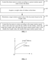
FIG. 2 is a graph of a preset function according to embodiments of the present application. -
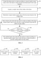
FIG. 3 is another flowchart of the method for controlling a clothes dryer according to embodiments of the present application. -
FIG. 4 is a diagram illustrating the structure of an apparatus for controlling a clothes dryer according to embodiments of the present application. -
FIG. 5 is a diagram illustrating the structure of a clothes dryer according to embodiments of the present application. - Embodiments of the present application provide a method and apparatus for controlling a clothes dryer, a clothes dryer, and a storage medium to satisfy the control requirements in various application scenarios and improve the clothes drying effect.
- The present application is described hereinafter in conjunction with drawings and embodiments.
-
FIG. 1 is a flowchart of a method for controlling a clothes dryer according to embodiments of the present application. This method can be executed by an apparatus for controlling a clothes dryer according to embodiments of the present application. The apparatus may be implemented by software and/or hardware. In an embodiment, the apparatus may be integrated in a clothes dryer. The clothes dryer may be, for example, a clothes drying machine. The following describes an example in which the apparatus is integrated in the clothes dryer. Referring toFIG. 1 , the method includes the following steps: - In
step 101, the drum motor is controlled to rotate according to a preset rotation speed value to drive the drum. - For example, the clothes dryer may include a drum driven by a drum motor and a fan driven by a fan motor. The drum motor and the fan motor are independent of each other. The drum motor and the fan motor may have the same or different performance parameters. The drum motor may be either a fixed-frequency motor or a variable-frequency motor while the fan motor may be a variable-frequency motor. The preset rotation speed value may be preset according to theoretical data or experimental data. This value affects the rotation speed of the drum. Typically, when the drum rotates at around 50 revolutions per minute (RPM), the clothes can be well rotated and scattered, facilitating drying. Therefore, the preset rotation speed value may be set based on this rotation speed. One or more preset rotation speed values may be provided so that the drum can be controlled to rotate at a fixed speed or at a variable speed.
- For example, to improve the clothes drying effect and shorten the clothes drying duration, it is feasible to remove water from the clothes, put the water-removed clothes into the drum of the clothes dryer, and then use the drum motor to drive the drum to rotate according to the preset rotation speed value after the clothes dryer is started. For example, to prevent the clothes from tangling and clumping together inside the drum, it is feasible to drive the drum to rotate forwards and backwards for the same duration, for example, rotate forwards for one minute, then backwards for one minute, then forwards for one minute, and so on.
- In
step 102, a weight value of clothes in the drum is acquired. - For example, the weight value may be the initial weight value of the clothes placed in the drum, that is, the weight value of the clothes not dried. Alternatively, the weight value may be the real-time weight value of the clothes, that is, the weight value acquired in real time in the process of drying the clothes. For example, the weight value of the clothes may be acquired in the following manner:
- Manner one: At least one of the load power or the load current of the drum motor is acquired; and the weight value of the clothes is determined based on the at least one of the load power or the load current. That is, the load power of the drum motor and the load current of the drum motor are increased after the clothes are put into the drum; and it is feasible to detect the at least one of the load power or the load current of the drum motor before the clothes are put into the drum and the at least one of the load power or the load current of the drum motor after the clothes are put into the drum and calculate the weight value of the clothes based on the difference between the at least one of the load power or the load current of the drum motor before the clothes are put into the drum and the at least one of the load power or the load current of the drum motor after the clothes are put into the drum.
- Manner two: A clothes collision frequency and a clothes collision amplitude that are detected by a clothes sensor in the drum are acquired; and the weight value of the clothes is determined based on the clothes collision frequency and the clothes collision amplitude. That is, a clothes sensor may be disposed on the front support of the drum, the clothes sensor may be a bimetallic sensor, the clothes tumbling in the drum may touch the clothes sensor, the clothes sensor may be connected to an oscillating circuit, the oscillating circuit may detect the resistance value of the clothes, the clothes collision frequency and the clothes collision amplitude may be calculated according to the resistance value of the clothes, and the weight value of the clothes may be calculated according to the clothes collision frequency and the clothes collision amplitude.
- The preceding two manners of measuring the weight of the clothes are examples not intended to limit the embodiments. In practical use, the weight of the clothes may be measured in other manners according to the requirements.
- In
step 103, a target rotation speed value of the fan motor is determined based on the weight value. - For example, the target rotation speed value may be determined according to preset weight-rotation speed relationship information, the weight-rotation speed relationship information may include a rotation speed value corresponding to each weight value, the target rotation speed value may be obtained by querying the weight-rotation speed relationship information based on the current weight value of the clothes, and the weight-rotation speed relationship information may be set according to experiments or experience. In an embodiment, the weight-rotation speed relationship information may be stored in the clothes dryer in the form of a table, for example, Table 1.
Table 1 Weight Value of the Clothes Rotation Speed Value of the Fan Motor A1 B1 A2 B2 A3 B3 A4 B4 - In the weight-rotation speed relationship information listed in Table 1, the larger the weight value, the larger the rotation speed value; or the smaller the weight value, the smaller the target rotation speed value.
- For example, it is feasible to determine the target rotation speed value of the fan motor based on the weight value by using a preset function. The preset function includes a linear function or a quadratic function. The independent variable of the preset function is the weight. The dependent variable of the preset function is the rotation speed.
- For example, as shown in
FIG. 2 , the preset function is a quadratic function in the following form:
- y indicates the rotation speed. x indicates the weight. a, b, and c are all parameters. The value of a, the value of b, and the value of c are all greater than 0. For example, c > 1000.
- Illustratively, as shown in
FIG. 2 , the preset function may also be a primary function in the following manner:
- It can be learned from the graph of the primary function and the quadratic function shown in
FIG. 2 that the larger the weight value, the larger the target rotation speed value; or the smaller the weight value, the smaller the target rotation speed value. - For example, the value range of the rotation speed of the fan motor may be [2000 RPM, 3000 RPM], and the value range of the weight may be [0, 10 kg], that is, 0 kg corresponds to 2000 RPM, and 10 kg corresponds to 3000 RPM, thus ensuring the drying speed of the clothes.
- In
step 104, the fan motor is controlled to rotate according to the target rotation speed value to drive the fan to provide dry airflow for the clothes. The larger the weight value, the larger the target rotation speed value; or the smaller the weight value, the smaller the target rotation speed value. - In an example, the fan motor may be controlled to rotate at a fixed speed according to the target rotation speed value to drive the fan or may be controlled to rotate at a variable speed according to the target rotation speed value to drive the fan. For example, when the weight value is the initial weight value of the clothes, it is feasible to determine the fixed target rotation speed value of the fan motor based on the initial weight value and control the fan motor to rotate at a fixed speed according to the fixed target rotation speed value to drive the fan to rotate, that is, rotate at a constant speed in the process of drying the clothes. Alternatively, when the weight value is the real-time weight value of the clothes, it is feasible to determine the real-time target rotation speed value of the fan motor based on the real-time weight value and control the fan motor to rotate at a variable speed according to the real-time target rotation speed value, that is, rotate at a speed that varies with the weight of the clothes in the process of drying the clothes. The variable speed varies as follows: The lighter the clothes (the smaller the weight value), the lower the rotation speed (the smaller the rotation speed); and the heavier the clothes, the higher the rotation speed.
- The clothes dryer of embodiments of the present application uses double drives. The drum and the fan of the clothes dryer are driven independently of each other. The drum can be driven by the drum motor while the fan can be driven by the fan motor. The rotation speed of the drum is independent of the rotation speed of the fan, offering flexibility in control and catering to a wider range of control requirements in various application scenarios. Moreover, the driving speed of the fan motor can be determined on site based on the weight of the clothes, ensuring that the rotation speed of the fan is better matched to the actual application scenario and thus enhancing the clothes drying effectiveness.
- In an embodiment, the clothes dryer may include multiple fans driven by a fan motor, and the airflow direction of each fan is adjustable. These fans may be driven by a single fan motor or by different fan motors. When drying clothes, all of the multiple fans or part of the multiple fans may be driven simultaneously. The number of driven fans may be determined according to the actual requirements.
- That is, the step of controlling the fan motor to rotate according to the target rotation speed value to drive the fan may include the following:
- (1) The target fan is selected from the multiple fans.
- For example, the target fan may be selected from the multiple fans according to the weight value of the clothes and/or a preset clothes drying duration.
(2) The fan motor is controlled to rotate according to the target rotation speed value to drive the target fan. - For example, in practical use, the number of fans to be driven may be determined based on the weight value of the clothes. The larger the weight of the clothes, the more the fans to be driven. For example, when there are a total of two fans, it is feasible to drive one fan when there are fewer clothes and drive two fans simultaneously when there are more clothes. Alternatively, the number of fans to be driven may also be determined based on the drying duration set by the user. The shorter the drying duration, the more the fans to be driven. For example, there are a total of four fans, the four fans may be driven when the preset clothes drying duration is 1.5 hours, and two of the four fans may be driven when the preset duration is three hours. Alternatively, the number of fans to be driven may also be determined based on both the weight value of the clothes and the preset clothes drying duration.
- It is feasible to adjust the airflow directions of the fans in the following manner: The humidity of the clothes in the drum is detected so that a humidity distribution map is obtained. For the area having a higher humidity on the distribution map, it is feasible to adjust the airflow directions of the fans such that the fans focally blow air to the area having a higher humidity to increase the clothes drying speed or it is feasible to adjust the airflow directions of the fans such that the fans can evenly blow air to the drum.
- In an embodiment, it is feasible to use natural wind to dry the clothes, that is, control the fan motor to drive the fan to bring natural wind into the drum to make moisture in the clothes in the drum evaporate so that the clothes are dried. The temperature of natural wind is affected by the ambient temperature. The higher the ambient temperature, the higher the temperature of natural wind, and the faster the clothes are dried. In practical use, it is feasible to determine the target rotation speed value of the fan motor based on a combination of the ambient temperature and the weight of the clothes.
- For example, it is feasible to determine the current ambient temperature first, determine the target rotation speed range based on the current ambient temperature, and then determine the target rotation speed value from the target rotation speed range based on the weight value of the clothes. In practical use, different ambient temperatures may correspond to different rotation speed ranges. The relationship between the ambient temperatures and the rotation speed ranges may be preset according to actual requirements. For example, if the drying speed is the primary factor taken into consideration, the faster the drying speed, the better, and it is feasible to configure that the lower the ambient temperature, the higher the rotation speed in the rotation speed range and it is feasible to improve the rotation speed to alleviate the slow drying speed caused by a low ambient temperature (low temperature of dry airflow). For another example, if energy saving is the primary factor taken into consideration, the smaller the energy consumption, the better, it is feasible to configure that the higher the ambient temperature, the lower the rotation speed in the rotation speed range and it is feasible to use high-temperature natural wind (high-temperature dry airflow) to alleviate the slow drying speed caused by a low rotation speed. In practical use, it is also feasible to set the relationship between the ambient temperatures and the rotation speed ranges based on other factors taken into consideration. This is not limited here.
- In an embodiment, it is also feasible to use warm air to dry the clothes, that is, it is feasible to add a heater to the air outlet of the fan, use the heater to heat the natural wind from the fan and bring the heated natural wind to the drum, and use the warm air to make evaporated moisture in the clothes in the drum to dry the clothes. The heater may be, for example, an electric heating wire or a semiconductor heater. When using warm air to dry the clothes, the temperature of the warm air may be set according to the material of the clothes. Generally, the temperature of the warm air should not exceed 60°, optimally 55°. If the temperature is too high, the clothes may be damaged; and if the temperature is too low, the drying speed is slow.
-
FIG. 3 shows a method for controlling a clothes dryer that uses warm air to dry clothes. As shown inFIG.3 , the method may include the following steps: - In
step 301, the drum motor is controlled to rotate according to a preset rotation speed value to drive the drum to rotate forwards and backwards for the same duration. - The preset rotation speed value may include one or more rotation speed values. That is, the drum motor may rotate at a fixed speed or may rotate at a variable speed. The drum motor is configured to drive the drum to rotate forwards and backwards for the same duration, preventing the clothes from tangling and clumping together inside the drum and increasing the clothes drying speed.
- In
step 302, a weight value of the clothes in the drum is acquired. - For example, the weight value of the clothes may be determined based on the load power and/or the load current of the drum motor or may be determined based on the clothes collision frequency and the clothes collision amplitude that are detected by the clothes sensor in the drum. The determined weight value of the clothes may be the initial weight value of the clothes or the real-time weight value of the clothes.
- In
step 303, a target rotation speed value of the fan motor is determined based on the weight value. - The larger the weight value, the larger the target rotation speed value; or the smaller the weight value, the smaller the target rotation speed value. In embodiments of the present application, the rotation speed value of the fan motor may not be affected by the rotation speed value of the drum motor. The fan motor and the drum motor may have the same or different rotation speed values according to the actual requirements.
- In
step 304, the heater is started, and the fan motor is controlled to rotate according to the target rotation speed value to drive the fan to rotate forwards to provide dry airflow for the clothes. - After the heater is started, the heater heats the sucked natural wind to obtain hot wind, and the fan motor drives the fan to rotate to bring the hot wind into the drum, making moisture in the clothes in the drum evaporate.
- In
step 305, it is determined whether a clothes cooling condition is satisfied; if the clothes cooling condition is satisfied,step 306 is performed; and if the clothes cooling condition is not satisfied,step 304 is performed. - Cooling means the heating stops, that is, the heater stops heating, but the fan motor continues working, and low-temperature natural wind enters the drum to cool the clothes to prevent the clothes from wrinkling. The clothes cooling condition may be, for example, a time condition, a clothes dryness degree condition, or a temperature condition. For example, it is feasible to determine whether the execution duration of the clothes drying program reaches a specified duration and determine that the cooling condition is satisfied when the execution duration of the clothes drying program reaches the specified duration; or it is feasible to determine whether the dryness degree of the clothes reaches a specified dryness degree and determine that the cooling condition is satisfied when the dryness degree of the clothes reaches the specified dryness degree; or it is feasible to determine whether the temperature in the drum reaches a specified temperature and determine that the cooling condition is satisfied when the temperature in the drum reaches the specified temperature.
- For example, the total running duration of the clothes drying program is 2 hours. This duration is divided into two phases. The first phase is the drying phase: the first 1.5 hours. The second phase is the cooling phase: the last 0.5 hours. When it is detected that the clothes drying program runs to 1.5 hours, it is determined that the clothes cooling condition is reached.
- For example, it is feasible to detect the dryness degree of the clothes in the drum. It is feasible to detect the dryness degree of the clothes according to variation of the weight of the clothes. For example, when the amount of variation of the weight of the clothes is less than a fixed value (for example, 0.1 kg) within a specified duration (for example, 5 minutes), it may be determined that the dryness degree of the clothes reaches the specified dryness degree. It is also feasible to determine the dryness degree of the clothes by detecting humidity of air released from the drum. For example, when the detected humidity of the air released from the drum is continuously less than a specified humidity value (for example, 10%) within a specified duration (for example, 3 minutes), it may be determined that the dryness degree of the clothes reaches the specified dryness degree. Once the clothes reach the specified dryness degree, it is determined that the clothes cooling condition is satisfied.
- For example, it is feasible to detect the temperature in the drum. When the temperature in the drum is higher than a specified temperature (for example, 65 degrees), it is determined that the clothes cooling condition is satisfied. The heater may be aged or faulty, causing an excessively high heating temperature that is higher than the rated heating temperature set by the user. To avoid damage to the clothes due to the high temperature, a cooling program may be started when the temperature in the drum is detected to be higher than the specified temperature.
- In
step 306, the heater is turned off, and the fan motor is controlled to rotate according to a specified rotation speed value to drive the fan to rotate forwards to provide cooling airflow for the clothes. - The specified rotation speed value may be set to a fixed value according to the actual requirements.
- The clothes dryer of embodiments of the present application uses double drives. The drum and the fan of the clothes dryer are driven independently of each other. The drum may be driven by the drum motor while the fan may be driven by the fan motor. The rotation speed of the drum is independent of the rotation speed of the fan, offering flexibility in control and catering to a wider range of control requirements in various application scenarios. Moreover, the driving speed of the fan motor can be determined on site based on the weight of the clothes, ensuring that the rotation speed of the fan is better matched to the actual application scenario and thus enhancing the clothes drying effectiveness.
-
FIG. 4 is a diagram illustrating the structure of an apparatus for controlling a clothes dryer according to embodiments of the present application. The apparatus includes a drum driven by a drum motor and a fan driven by a fan motor. The apparatus is applicable to the method for controlling the clothes dryer according to any embodiment of the present application. As shown inFIG. 4 , the apparatus includes adrum control module 401, anacquisition module 402, adetermination module 403, and afan control module 404. - The
drum control module 401 is configured to control the drum motor to rotate according to a preset rotation speed value to drive the drum. - The
acquisition module 402 is configured to acquire a weight value of clothes in the drum. - The
determination module 403 is configured to determine a target rotation speed value of the fan motor based on the weight value. - The
fan control module 404 is configured to control the fan motor to rotate according to the target rotation speed value to drive the fan to provide dry airflow for the clothes. - The larger the weight value, the larger the target rotation speed value; or the smaller the weight value, the smaller the target rotation speed value.
- In an embodiment, the weight value of the clothes includes an initial weight value of the clothes.
- The
determination module 403 is configured to determine a fixed target rotation speed value of the fan motor based on the initial weight value. - The
fan control module 404 is configured to control the fan motor to rotate at a fixed speed according to the fixed target rotation speed value to drive the fan. - In an embodiment, the weight value of the clothes includes a real-time weight value of the clothes.
- The
determination module 403 is configured to determine a real-time target rotation speed value of the fan motor based on the real-time weight value. - The
fan control module 404 is configured to control the fan motor to rotate at a variable speed according to the real-time target rotation speed value to drive the fan. - In an embodiment, the
drum control module 401 is configured to control the drum motor to rotate according to the preset rotation speed value to drive the drum to rotate forwards and backwards. - In an embodiment, the
drum control module 401 is configured to control the drum motor to rotate according to the preset rotation speed value to drive the drum to rotate forwards and backwards for the same duration. - In an embodiment, the
determination module 403 is configured to determine the target rotation speed value of the fan motor based on the weight value by using a preset function. The preset function includes a linear function or a quadratic function. The independent variable of the preset function is the weight. The dependent variable of the preset function is the rotation speed. - In an embodiment, the
acquisition module 402 is configured to acquire at least one of load power or load current of the drum motor and determine the weight value of the clothes based on the at least one of the load power or the load current. - In an embodiment, the
acquisition module 402 is configured to acquire a clothes collision frequency and a clothes collision amplitude that are detected by a clothes sensor in the drum; and determine the weight value of the clothes based on the clothes collision frequency and the clothes collision amplitude. - In an embodiment, the
fan control module 404 is configured to start a heater and control the fan motor to rotate according to the target rotation speed value to drive the fan to provide the dry airflow for the clothes. - In an embodiment, the apparatus also includes a cooling module.
- The cooling module is configured to determine whether a clothes cooling condition is satisfied; and in response to determining that the clothes cooling condition is satisfied, turn off the heater and control the fan motor to rotate according to a specified rotation speed value to drive the fan to provide cooling airflow for the clothes.
- In an embodiment, multiple fans are provided, the fans are driven by the fan motor, and the
fan control module 404 is configured to determine a target fan from the multiple fans; and control the fan motor to rotate according to the target rotation speed value to drive the target fan. - In an embodiment, the
determination module 403 determines the target fan from the multiple fans by determining the target fan from the multiple fans according to at least one of the weight value or preset clothes drying duration. - It is to be known by those skilled in the art that for the sake of convenience and conciseness in description, the classification of the preceding function modules is provided as an example, and in practical applications, the preceding functions may be performed by different functional modules according to needs, that is, the internal structure of the apparatus is divided into different functional modules to perform all or part of the preceding functions. For the working process of the function modules, see the corresponding process in the preceding method embodiment. The details are not described here.
- The apparatus of embodiments of the present application includes a drum driven by a drum motor and a fan driven by a fan motor, that is, double drives. The apparatus can control the drum motor to rotate according to a preset rotation speed value to drive the drum; acquire the weight value of clothes in the drum; determine the target rotation speed value of the fan motor based on the weight value; and control the fan motor to rotate according to the target rotation speed value to drive the fan to provide dry airflow for the clothes. The larger the weight value, the larger the target rotation speed value; or the smaller the weight value, the smaller the target rotation speed value. The clothes dryer in embodiments of the present application uses double drives. The drum and the fan of the clothes dryer are driven independently of each other. The drum may be driven by the drum motor while the fan may be driven by the fan motor. The rotation speed of the drum is independent of the rotation speed of the fan, offering flexibility in control and catering to a wider range of control requirements in various application scenarios. Moreover, the driving speed of the fan motor can be determined on site based on the weight of the clothes, ensuring that the rotation speed of the fan is better matched to the actual application scenario and thus enhancing the clothes drying effectiveness.
- Embodiments of the present application also provide a clothes dryer. The clothes dryer includes a memory, a processor, and a computer program stored in the memory and executable on the processor. The processor is configured to, when executing the computer program, perform the method for controlling a clothes dryer according to any embodiment of the present application.
- Embodiments of the present application also provide a computer-readable storage medium storing a computer program which, when executed by a processor, causes the processor to perform the method for controlling a clothes dryer according to any embodiment of the present application.
- The storage medium may be a non-transitory storage medium.
-
FIG. 5 is a diagram illustrating the structure of acomputer system 500 for performing the method for controlling a clothes dryer according to any embodiment of the present application. The clothes dryer ofFIG. 5 is an example not intended to limit the function and application scope of embodiments of the present application. - As shown in
FIG. 5 , thecomputer system 500 includes a central processing unit (CPU) 501. Thecomputer system 500 may execute various appropriate actions and processing according to a program stored in a read-only memory (ROM) 502 or a program loaded into a random access memory (RAM) 503 from astorage portion 508. Various programs and data required for operations of thecomputer system 500 may also be stored in theRAM 503. TheCPU 501, theROM 502, and theRAM 503 are connected to each other by abus 504. An input/output (I/O)interface 505 is also connected to thebus 504. - The following components are connected to the I/O interface 505: an
input portion 506 such as a keyboard or a mouse; anoutput portion 507 such as a cathode ray tube (CRT), a liquid crystal display (LCD), or a speaker; astorage portion 508 such as a hard disk; and acommunication portion 509 of a network interface card such as a local area network (LAN) card or a modem. Thecommunication portion 509 performs communication processing through a network such as the Internet. Adrive 510 is also connected to the I/O interface 505 as required. Aremovable medium 511 such as a disk, an optical disc, a magneto-optical disc, or a semiconductor storage device is installed on thedrive 510 as required, allowing a computer program read from theremovable medium 511 to be installed into thestorage portion 508 as required. - According to embodiments of the present application, the process described above with reference to the flowchart may be implemented as a computer software program. For example, this embodiment of the present application includes a computer program product. The computer program product includes a computer program carried in a computer-readable medium. The computer program includes program codes for performing the method shown in the flowchart. In such embodiments, the computer program may be downloaded from a network and installed through the
communication portion 509 and/or may be installed through thestorage portion 511. When the computer program is executed by theCPU 501, the preceding functions defined in the system of the present application are executed. - The computer-readable medium described above in the present application may be a computer-readable signal medium or a computer-readable storage medium or any combination thereof. The computer-readable storage medium, for example, may be, but is not limited to, an electrical, magnetic, optical, electromagnetic, infrared, or semiconductor system, apparatus, or device, or any combination thereof. The computer-readable storage medium may include, but is not limited to, an electrical connection having one or more wires, a portable computer disk, a hard disk, a random access memory (RAM), a read-only memory (ROM), an erasable programmable read-only memory (EPROM) or flash memory, an optical fiber, a portable compact disc read-only memory (CD-ROM), an optical memory device, a magnetic memory device, or any suitable combination thereof. In this application, the computer-readable storage medium may be any tangible medium including or storing a program. The program may be used by or used in conjunction with an instruction execution system, apparatus, or element. In embodiments of the present application, the computer-readable signal medium may include a data signal propagated on a base band or as part of a carrier. Computer-readable program codes are carried in the data signal. The data signal propagated in this manner may be in multiple forms and includes, and is not limited to, an electromagnetic signal, an optical signal, or any suitable combination thereof. The computer-readable signal medium may also be any computer-readable medium except the computer-readable storage medium. The computer-readable medium may send, propagate or transmit a program used by or used in conjunction with an instruction execution system, apparatus or device. The program codes included on the computer-readable medium may be transmitted by using any suitable medium, including, but not limited to, a wireless medium, a wired medium, an optical cable, radio frequency (RF), and the like, or any suitable combination thereof.
- The flowcharts and block diagrams in the drawings show the possible architecture, function and operation of the system, method and computer program product according to various embodiments of the present application. In this regard, each block in the flowcharts or block diagrams may represent a module, a program segment, or part of codes that contains one or more executable instructions for implementing specified logical functions. It is to be noted that in some alternative implementations, the functions marked in the blocks may occur in an order different from those marked in the drawings. For example, two successive blocks may, in fact, be executed substantially in parallel or in a reverse order, which depends on the functions involved. It is also to be noted that each block in the block diagrams or flowcharts and a combination of blocks in the block diagrams or flowcharts may be implemented by a special-purpose hardware-based system which executes specified functions or operations, or a combination of special-purpose hardware and computer instructions.
- The modules and/or units involved in the embodiments of the present application may be implemented by software or hardware. The described modules and/or units can also be disposed in the processor. For example, the processor includes a drum control module, an acquisition module, a determination module, and a fan control module. The name of a module is not intended to limit the module in a certain circumstance.
- In another aspect, the present application also provides a computer-readable medium. The computer-readable medium may be included in a device described in the preceding embodiments or may exist separately without being installed in the device. The computer-readable medium carries one or more programs. When the one or more programs are executed by the device, the device is configured to control the drum motor to rotate according to a preset rotation speed value to drive the drum; acquire the weight value of clothes in the drum; determine the target rotation speed value of the fan motor based on the weight value; and control the fan motor to rotate according to the target rotation speed value to drive the fan to provide dry airflow for the clothes. The larger the weight value, the larger the target rotation speed value; or the smaller the weight value, the smaller the target rotation speed value.
- The clothes dryer according to embodiments of the present application includes a drum driven by a drum motor and a fan driven by a fan motor, that is, double drives. The clothes dryer can control the drum motor to rotate according to a preset rotation speed value to drive the drum; acquire the weight value of clothes in the drum; determine the target rotation speed value of the fan motor based on the weight value; and control the fan motor to rotate according to the target rotation speed value to drive the fan to provide dry airflow for the clothes. The larger the weight value, the larger the target rotation speed value; or the smaller the weight value, the smaller the target rotation speed value. On other words, the clothes dryer of embodiments of the present application uses double drives. The drum and the fan of the clothes dryer are driven independently of each other. The drum can be driven by the drum motor while the fan can be driven by the fan motor. The rotation speed of the drum is independent of the rotation speed of the fan, offering flexibility in control and catering to a wider range of control requirements in various application scenarios. Moreover, the driving speed of the fan motor can be determined on site based on the weight of the clothes, ensuring that the rotation speed of the fan is better matched to the actual application scenario and thus enhancing the clothes drying effectiveness.
- It is to be understood by those skilled in the art that various modifications, combinations, subcombinations, and substitutions may be made to embodiments of the present application according to design requirements and other factors.
Claims (15)
- A method for controlling a clothes dryer, wherein the clothes dryer comprises a drum driven by a drum motor and a fan driven by a fan motor, and the method comprises:controlling the drum motor to rotate according to a preset rotation speed value to drive the drum;acquiring a weight value of clothes in the drum;determining a target rotation speed value of the fan motor based on the weight value; andcontrolling the fan motor to rotate according to the target rotation speed value to drive the fan to provide dry airflow for the clothes,wherein the larger the weight value, the larger the target rotation speed value; or the smaller the weight value, the smaller the target rotation speed value.
- The method of claim 1, wherein the weight value of the clothes comprises an initial weight value of the clothes;determining the target rotation speed value of the fan motor based on the weight value comprises determining a fixed target rotation speed value of the fan motor based on the initial weight value; andcontrolling the fan motor to rotate according to the target rotation speed value to drive the fan comprises controlling the fan motor to rotate at a fixed speed according to the fixed target rotation speed value to drive the fan.
- The method of claim 1, wherein the weight value of the clothes comprises a real-time weight value of the clothes;determining the target rotation speed value of the fan motor based on the weight value comprises determining a real-time target rotation speed value of the fan motor based on the real-time weight value; andcontrolling the fan motor to rotate according to the target rotation speed value to drive the fan comprises controlling the fan motor to rotate at a variable speed according to the real-time target rotation speed value to drive the fan.
- The method of claim 1, wherein controlling the drum motor to rotate according to the preset rotation speed value to drive the drum comprises:
controlling the drum motor to rotate according to the preset rotation speed value to drive the drum to rotate forwards and backwards. - The method of claim 4, wherein controlling the drum motor to rotate according to the preset rotation speed value to drive the drum to rotate forwards and backwards comprises:
controlling the drum motor to rotate according to the preset rotation speed value to drive the drum to rotate forwards and backwards for a same duration. - The method of claim 1, wherein determining the target rotation speed value of the fan motor based on the weight value comprises:determining the target rotation speed value of the fan motor based on the weight value by using a preset function, wherein the preset function comprises a linear function or a quadratic function,an independent variable of the preset function is a weight, and a dependent variable of the preset function is a rotation speed.
- The method of claim 1, wherein acquiring the weight value of the clothes in the drum comprises:acquiring at least one of load power of the drum motor or load current of the drum motor; anddetermining the weight value of the clothes based on the at least one of the load power or the load current.
- The method of claim 1, wherein acquiring the weight value of the clothes in the drum comprises:acquiring a clothes collision frequency and a clothes collision amplitude that are detected by a clothes sensor in the drum; anddetermining the weight value of the clothes based on the clothes collision frequency and the clothes collision amplitude.
- The method of claim 1, wherein controlling the fan motor to rotate according to the target rotation speed value to drive the fan to provide the dry airflow for the clothes comprises:
starting a heater and controlling the fan motor to rotate according to the target rotation speed value to drive the fan to provide the dry airflow for the clothes. - The method of claim 9, further comprising:determining whether a clothes cooling condition is satisfied; andin response to the clothes cooling condition being satisfied, turning off the heater andcontrolling the fan motor to rotate according to a specified rotation speed value to drive the fan to provide cooling airflow for the clothes.
- The method of claim 1, wherein a plurality of fans are provided, the plurality of fans are driven by the fan motor, and controlling the fan motor to rotate according to the target rotation speed value to drive the fan further comprises:determining a target fan from the plurality of fans; andcontrolling the fan motor to rotate according to the target rotation speed value to drive the target fan.
- The method of claim 11, wherein determining the target fan from the plurality of fans comprises:determining, according to at least one of the weight value or a preset clothes drying duration,the target fan from the plurality of fans.
- An apparatus for controlling a clothes dryer, wherein the clothes dryer comprises a drum driven by a drum motor and a fan driven by a fan motor, and the apparatus comprises:a drum control module configured to control the drum motor to rotate according to a preset rotation speed value to drive the drum;an acquisition module configured to acquire a weight value of clothes in the drum;a determination module configured to determine a target rotation speed value of the fan motor based on the weight value; anda fan control module configured to control the fan motor to rotate according to the target rotation speed value to drive the fan to provide dry airflow for the clothes,wherein the larger the weight value, the larger the target rotation speed value; or the smaller the weight value, the smaller the target rotation speed value.
- A clothes dryer, comprising a memory, a processor, and a computer program stored in the memory and executable on the processor, wherein the processor is configured to, when executing the computer program, perform the method for controlling the clothes dryer according to any one of claims 1 to 12.
- A computer-readable storage medium storing a computer program which, when executed by a processor, causes the processor to perform the method for controlling the clothes dryer according to any one of claims 1 to 12.
Applications Claiming Priority (2)
| Application Number | Priority Date | Filing Date | Title |
|---|---|---|---|
| CN202111503663.1A CN114438761A (en) | 2021-12-10 | 2021-12-10 | Control method and device of clothes drying equipment, clothes drying equipment and storage medium |
| PCT/CN2022/131328 WO2023103710A1 (en) | 2021-12-10 | 2022-11-11 | Control method and apparatus for clothes drying device, clothes drying device and storage medium |
Publications (2)
| Publication Number | Publication Date |
|---|---|
| EP4446495A1 true EP4446495A1 (en) | 2024-10-16 |
| EP4446495A4 EP4446495A4 (en) | 2025-11-05 |
Family
ID=81363651
Family Applications (1)
| Application Number | Title | Priority Date | Filing Date |
|---|---|---|---|
| EP22903133.1A Pending EP4446495A4 (en) | 2021-12-10 | 2022-11-11 | CONTROL METHOD AND DEVICE FOR A TONGSDRYER, TONGSDRYER AND STORAGE MEDIUM |
Country Status (6)
| Country | Link |
|---|---|
| US (1) | US20250043500A1 (en) |
| EP (1) | EP4446495A4 (en) |
| JP (1) | JP2024544775A (en) |
| CN (1) | CN114438761A (en) |
| AU (1) | AU2022404329B2 (en) |
| WO (1) | WO2023103710A1 (en) |
Families Citing this family (4)
| Publication number | Priority date | Publication date | Assignee | Title |
|---|---|---|---|---|
| CN114438761A (en) * | 2021-12-10 | 2022-05-06 | 青岛海尔洗涤电器有限公司 | Control method and device of clothes drying equipment, clothes drying equipment and storage medium |
| CN117306225A (en) * | 2022-06-21 | 2023-12-29 | 松下家电(中国)有限公司 | Control method of clothing care machine |
| CN115821557B (en) * | 2022-12-22 | 2025-12-19 | Tcl家用电器(合肥)有限公司 | Clothes dryer, control method and control device thereof and storage medium |
| CN119221247A (en) * | 2023-06-30 | 2024-12-31 | 无锡小天鹅电器有限公司 | Control method, control device, clothes treatment equipment and medium |
Family Cites Families (21)
| Publication number | Priority date | Publication date | Assignee | Title |
|---|---|---|---|---|
| JP2000140493A (en) * | 1998-11-17 | 2000-05-23 | Toshiba Corp | Clothes dryer |
| JP2002233695A (en) * | 2001-02-13 | 2002-08-20 | Matsushita Electric Ind Co Ltd | Clothes dryer |
| JP4091798B2 (en) * | 2002-06-06 | 2008-05-28 | シャープ株式会社 | Dryer |
| JP4128095B2 (en) * | 2003-03-07 | 2008-07-30 | 象印マホービン株式会社 | Dehumidifier |
| JP2007143631A (en) * | 2005-11-24 | 2007-06-14 | Mitsubishi Electric Corp | Clothes dryer and operation method thereof |
| KR101337742B1 (en) * | 2010-08-09 | 2013-12-06 | 위니아만도 주식회사 | Method for controlling fan of clothes dryer |
| JP2014008104A (en) * | 2012-06-28 | 2014-01-20 | Hitachi Appliances Inc | Washing machine or washing and drying machine |
| CN202671922U (en) * | 2012-07-13 | 2013-01-16 | 吕行 | Condensing type clothes dryer |
| EP2735643A1 (en) * | 2012-11-26 | 2014-05-28 | Electrolux Home Products Corporation N.V. | A method for controlling a laundry dryer including a fan motor for driving a drying air stream fan with a variable speed |
| EP2735642A1 (en) * | 2012-11-26 | 2014-05-28 | Electrolux Home Products Corporation N.V. | A method for controlling a laundry dryer with a variable drum rotation speed and a variable fan rotation speed |
| JP6486037B2 (en) * | 2014-09-03 | 2019-03-20 | 東芝ライフスタイル株式会社 | Washing and drying machine |
| CN107805927A (en) * | 2016-09-09 | 2018-03-16 | 青岛海尔洗衣机有限公司 | Dryer |
| CN206873153U (en) * | 2016-11-29 | 2018-01-12 | 柯心安 | A kind of wall-hung type clothesdrier with row's clothes hook |
| KR102504577B1 (en) * | 2017-10-26 | 2023-03-02 | 삼성전자주식회사 | Clothes dryer and method for performing sterlization course thereof |
| KR20190127443A (en) * | 2018-05-04 | 2019-11-13 | 엘지전자 주식회사 | Laundry treating appratus and controlling method thereof |
| CN112095309B (en) * | 2019-05-31 | 2024-06-25 | 上海海尔洗涤电器有限公司 | A clothes dryer drying method, device, clothes dryer and storage medium |
| KR102838697B1 (en) * | 2019-11-21 | 2025-07-28 | 삼성전자주식회사 | Dryer and method for controlling the same |
| CN113584846A (en) * | 2020-04-30 | 2021-11-02 | 云米互联科技(广东)有限公司 | Fan control method, fan and computer readable storage medium |
| CN112941861B (en) * | 2021-01-29 | 2023-07-14 | 珠海格力电器股份有限公司 | Drying control method and control device for dryer |
| CN113638208B (en) * | 2021-08-04 | 2024-03-19 | 木卫智能科技(深圳)有限公司 | Clothes dryer crease-resist control method and clothes dryer |
| CN114438761A (en) * | 2021-12-10 | 2022-05-06 | 青岛海尔洗涤电器有限公司 | Control method and device of clothes drying equipment, clothes drying equipment and storage medium |
-
2021
- 2021-12-10 CN CN202111503663.1A patent/CN114438761A/en active Pending
-
2022
- 2022-11-11 WO PCT/CN2022/131328 patent/WO2023103710A1/en not_active Ceased
- 2022-11-11 US US18/717,867 patent/US20250043500A1/en active Pending
- 2022-11-11 AU AU2022404329A patent/AU2022404329B2/en active Active
- 2022-11-11 EP EP22903133.1A patent/EP4446495A4/en active Pending
- 2022-11-11 JP JP2024534469A patent/JP2024544775A/en active Pending
Also Published As
| Publication number | Publication date |
|---|---|
| CN114438761A (en) | 2022-05-06 |
| AU2022404329B2 (en) | 2026-02-12 |
| JP2024544775A (en) | 2024-12-04 |
| US20250043500A1 (en) | 2025-02-06 |
| WO2023103710A1 (en) | 2023-06-15 |
| EP4446495A4 (en) | 2025-11-05 |
| AU2022404329A1 (en) | 2024-07-18 |
Similar Documents
| Publication | Publication Date | Title |
|---|---|---|
| US20250043500A1 (en) | Method for controlling a clothes dryer, clothes dryer, and storage medium | |
| CN110438780B (en) | Drying control method and device and drying equipment | |
| CN107388662B (en) | Air conditioner/heat pump unit and control method and device thereof | |
| CN112900039B (en) | Heating drying control method and clothes treatment equipment with same | |
| EP2922992B1 (en) | A method for controlling a laundry dryer including a fan motor for driving a drying air stream fan with a variable speed | |
| EP2540907A1 (en) | Method for operating a tumble dryer | |
| CN115323738B (en) | Method for determining operation parameters, clothes treatment equipment and storage medium | |
| CN110531677A (en) | Gentle breeze control method, storage medium, controller and its Intelligent blower | |
| CN106871383A (en) | The control method and control device of air-conditioner, detachable air conditioner | |
| CN112994543B (en) | Control method and system for rotating speed of direct current brush motor, storage medium and blower | |
| EP2738303A1 (en) | A method for controlling a drying cycle of a laundry dryer | |
| CN112411152A (en) | Drying treatment method, device and laundry treatment device | |
| CN110285581A (en) | Anti-overflow control method, device and system and cooker | |
| US10598399B2 (en) | Air conditioner | |
| CN116005430B (en) | Control method and control system of clothes dryer, and clothes dryer | |
| CN116169928A (en) | Control method, device, air conditioner and storage medium of air conditioner sweeping motor | |
| CN103676994A (en) | Dehumidifying circuit, electric apparatus and dehumidifying method thereof, and electrical steamer | |
| CN113357716A (en) | Control method and controller for constant temperature and humidity system and constant temperature and humidity system | |
| US12231066B2 (en) | Two degrees of control through pulse width modulation interface | |
| CN115264883B (en) | Air Conditioner Airflow Temperature Control Method and Device | |
| CN202019334U (en) | Multi-mode motor drive circuit | |
| CN115679661B (en) | A clothes dryer and its control method | |
| CN115182143A (en) | Drying device control method, control equipment, drying equipment and medium | |
| CN114164629B (en) | Clothes dryer and control method thereof | |
| CN120158908A (en) | Fabric drying method, device, drying equipment and computer readable storage medium |
Legal Events
| Date | Code | Title | Description |
|---|---|---|---|
| STAA | Information on the status of an ep patent application or granted ep patent |
Free format text: STATUS: THE INTERNATIONAL PUBLICATION HAS BEEN MADE |
|
| PUAI | Public reference made under article 153(3) epc to a published international application that has entered the european phase |
Free format text: ORIGINAL CODE: 0009012 |
|
| STAA | Information on the status of an ep patent application or granted ep patent |
Free format text: STATUS: REQUEST FOR EXAMINATION WAS MADE |
|
| 17P | Request for examination filed |
Effective date: 20240619 |
|
| AK | Designated contracting states |
Kind code of ref document: A1 Designated state(s): AL AT BE BG CH CY CZ DE DK EE ES FI FR GB GR HR HU IE IS IT LI LT LU LV MC ME MK MT NL NO PL PT RO RS SE SI SK SM TR |
|
| DAV | Request for validation of the european patent (deleted) | ||
| DAX | Request for extension of the european patent (deleted) | ||
| A4 | Supplementary search report drawn up and despatched |
Effective date: 20251006 |
|
| RIC1 | Information provided on ipc code assigned before grant |
Ipc: D06F 58/38 20200101AFI20250929BHEP Ipc: D06F 58/50 20200101ALN20250929BHEP Ipc: D06F 103/04 20200101ALN20250929BHEP Ipc: D06F 103/32 20200101ALN20250929BHEP Ipc: D06F 105/30 20200101ALN20250929BHEP Ipc: D06F 105/48 20200101ALN20250929BHEP |