EP4446201A1 - Selbstlenkender selbstlenkender achsanhänger - Google Patents
Selbstlenkender selbstlenkender achsanhänger Download PDFInfo
- Publication number
- EP4446201A1 EP4446201A1 EP23167392.2A EP23167392A EP4446201A1 EP 4446201 A1 EP4446201 A1 EP 4446201A1 EP 23167392 A EP23167392 A EP 23167392A EP 4446201 A1 EP4446201 A1 EP 4446201A1
- Authority
- EP
- European Patent Office
- Prior art keywords
- trailer
- angle
- axle
- cylinder
- steering
- Prior art date
- Legal status (The legal status is an assumption and is not a legal conclusion. Google has not performed a legal analysis and makes no representation as to the accuracy of the status listed.)
- Withdrawn
Links
Images


Classifications
-
- B—PERFORMING OPERATIONS; TRANSPORTING
- B62—LAND VEHICLES FOR TRAVELLING OTHERWISE THAN ON RAILS
- B62D—MOTOR VEHICLES; TRAILERS
- B62D13/00—Steering specially adapted for trailers
- B62D13/04—Steering specially adapted for trailers for individually-pivoted wheels
-
- B—PERFORMING OPERATIONS; TRANSPORTING
- B62—LAND VEHICLES FOR TRAVELLING OTHERWISE THAN ON RAILS
- B62D—MOTOR VEHICLES; TRAILERS
- B62D6/00—Arrangements for automatically controlling steering depending on driving conditions sensed and responded to, e.g. control circuits
- B62D6/002—Arrangements for automatically controlling steering depending on driving conditions sensed and responded to, e.g. control circuits computing target steering angles for front or rear wheels
Definitions
- the invention relates to trailers, in particular agricultural trailers, of the type comprising two axles with at least one axle with steered wheels.
- the invention also relates incidentally to agricultural trailers equipped with a hydraulic suspension system capable of providing a level and tilt correction function.
- Agricultural trailers are designed to be coupled to a tractor to be towed by that tractor.
- the term "agricultural trailer” should be understood to cover all types of trailers, specialized or multi-role/multi-function, with the capacity to operate in fields as well as on the road. On the road, their speed can reach up to 40 km/h or even 50 km/h.
- the trailers in question may or may not have a front axle.
- the trailers in question can be used for various purposes: harvesting, transporting various materials and goods, earthworks.
- the trailers in question may be equipped with a tipper function or other motorized functions.
- a trailer may be used by several farmers, each having one or more tractors.
- Known systems for controlling the steering angle of the steered wheels use a connecting rod interposed between the trailer and the tractor. More precisely, one end of the connecting rod attached is to the tractor, at a point offset from the median longitudinal axis of the tractor, and the other end of the connecting rod is attached to an angle sensor which is usually located on the drawbar of the trailer.
- An example of such a system is known from the document FR2909632 .
- connecting rod and angle sensor is unfavorable from the point of view of the interoperability of tractors and trailers. Often an adjustment of the neutral position is necessary.
- the connecting rod hinders access to the space between the tractor and the trailer, while the operator needs access to this space, for example, to connect and disconnect hydraulic lines or an electrical connector, or to couple or uncouple a PTO shaft.
- the inventors therefore sought another solution to implement the function of controlling the orientation of the wheels of the steered axle, while increasing the interoperability between tractors and trailers.
- an agricultural trailer comprising a chassis and at least two axles (E1, E2), with at least one first axle (E1) with steered wheels, the trailer comprising a system for controlling a steering angle of the steered wheels of the first axle, called first angle ⁇ , the first angle ⁇ being controlled, via a first cylinder (3), by an on-board control unit (5), the control system providing for the supply of a longitudinal speed (VR) of the trailer, from at least one speed sensor and intended for the control unit (5), the trailer being characterized in that the steering system comprises a yaw motion sensor (2) fixed to a structural element of the trailer and delivering an instantaneous measurement of the yaw motion ( ⁇ ) to the control unit, the first angle ⁇ being made dependent at least on the yaw motion ( ⁇ ) and the longitudinal speed (VR).
- the steering system comprises a yaw motion sensor (2) fixed to a structural element of the trailer and delivering an instantaneous measurement of the yaw motion ( ⁇ ) to the control unit, the
- the yaw motion sensor may typically be a single-axis, or multi-axis, gyroscope or gyrometer, with at least one active axis oriented horizontally.
- the response time must be very short, it is necessary to react instantly to a small variation in the trailer heading. From this point of view, it is advantageous to have the control unit on board the trailer which directly reads the signals coming from the gyrometer, whereas if the control unit were in the tractor area, it would have to cross the ISObus interface or other CAN interface which would introduce detrimental delays.
- the local autonomous control system, in short circuit, on the trailer, makes it possible to obtain sufficiently short response times and satisfactory reactivity.
- control unit can still control the orientation of the wheels according to the indications provided to it by the real-time yaw movement sensor associated with the rotation speeds of the wheels.
- control unit here is an electrohydraulic control unit.
- structural element is meant the chassis of the trailer or another element rigidly connected to the chassis during normal operation.
- the yaw motion sensor is a gyrometer comprising at least a first axis of interest, said first axis of interest being oriented horizontally relative to the chassis of the trailer, thus forming the yaw motion sensor.
- the function G is either increasing or decreasing but not a mixture of both.
- the low threshold VRb is between 0.5 Km/h and 1.5 Km/h.
- the speed sensor is located at one or more wheels of the trailer.
- the trailer with its steering system is then completely autonomous from the point of view of signals and control.
- the speed sensor is installed on the tractor, either on a rotating toothed target with a wheel or by radar.
- the IsoBus standard or an existing J1939 bus is used to easily benefit from the existing forward speed information on the tractor.
- the wheel speed sensor(s) provide a direction of travel, i.e. Forward or Reverse. It turns out that knowing the direction of travel allows for different steering behavior, useful in this case because the sign of the yaw signal depends on the direction of travel of the trailer in the same curve.
- G (d ⁇ /dt,VRa) - G (d ⁇ /dt, -VRa)
- the first cylinder is a double-acting cylinder
- the control system further comprising at least one first distributor interposed between on the one hand a hydraulic pressure line and a return line, and on the other hand the two end ports of the double-acting cylinder. This provides positive control in both directions, with a balanced left/right symmetry for the steering control of the steered wheels.
- the first cylinder may be of the conventional type with a single output rod, but according to a variant illustrated in the figures, the cylinder may be of the type with two output rods diametrically opposed at the 2 respective ends.
- the first distributor is of the proportional control type, for example of the 5/3 or 4/3 type. By means of which a fine metering of the oil flow can be obtained.
- the output flow is adjustable according to the current control of the coil windings.
- the drawbar and the front portion of the trailer are devoid of any sensor apparatus for the function of the steerable axle(s). Access to the area between the tractor and the trailer is not hindered by any mechanical element such as a connecting rod, chain or sensor.
- the trailer may further comprise at least one second axle (E2, E3) with steered wheels, the steering system comprising a function for controlling the steering angle of the steered wheels of the second axle, forming a second angle ( ⁇ 2), said second angle being controlled via a second cylinder by the electrohydraulic control unit.
- system can be extended to 3 or more steering axles in the same logic.
- the steering system further comprises a roll motion sensor providing an instantaneous measurement of the roll motion ( ⁇ ), the trailer being able to further comprise a hydraulic suspension, with a left cylinder (61) and a right cylinder (62) for each axle, the electrohydraulic control unit controlling the left and right cylinders to keep the chassis substantially horizontal, even on sloping terrain.
- a roll motion sensor providing an instantaneous measurement of the roll motion ( ⁇ )
- the trailer being able to further comprise a hydraulic suspension, with a left cylinder (61) and a right cylinder (62) for each axle, the electrohydraulic control unit controlling the left and right cylinders to keep the chassis substantially horizontal, even on sloping terrain.
- the gyrometer comprises at least one second axis of interest, said second axis of interest being oriented vertically relative to the chassis of the trailer, thereby forming the roll motion sensor.
- the present invention also relates to an assembly comprising a tractor and a trailer as defined above, in which the interface between the tractor and the trailer comprises a conventional mechanical coupling, a supply hydraulic pressure and a supply of electrical power, the interface being devoid of a means for measuring an angle between a longitudinal axis of the trailer and a longitudinal axis of the tractor.
- a user console arranged in the tractor cab, to select one or more operating modes, to carry out manual or special commands. It should be noted that the user console does not intervene in the real-time control loop which makes it possible to control the orientation of the steered wheels of the first axle.
- a measurement of the current value of the angle ⁇ is provided, and the electrohydraulic control unit comprises a servo loop to permanently cancel an observed difference ( ⁇ - ⁇ c) between the setpoint and the actual value.
- the function G may include a neutral zone (ZN) around the zero speed, and in this neutral zone, the control is such that the first angle ⁇ is kept intact without change, said neutral zone being defined by a low threshold VRb, and the neutral zone being between -VRb and +VRb.
- an agricultural trailer comprising a chassis (11) and at least one or more axles, the trailer further comprising a hydraulic suspension system connecting the chassis to the axle(s) with a left cylinder (61) and a right cylinder (62) for each axle, the trailer comprising a function for controlling the attitude of the chassis ( ⁇ ) relative to the axle, the attitude angle being controlled, via the left and right cylinders, by a control unit on-board electrohydraulic control (5), the system further comprising a roll motion sensor fixed to a structural element of the trailer and delivering an instantaneous measurement of the roll motion ( ⁇ ), the electrohydraulic control unit controlling the left and right cylinders, as a function of the measured roll motion, to keep the chassis substantially horizontal, even on sloping terrain.
- the two cylinders of the same axle are controlled by two hydraulic lines, a first hydraulic line connected to end A of the first left cylinder and to end B of the right cylinder, while the second hydraulic line connected to end B of the first left cylinder and to end A of the right cylinder.
- This 'compound' control associates a left-hand rise with a right-hand fall and vice versa, and this is directly achieved in the hydraulic circuit.
- an inclinometer may be provided in addition to the vertical axis gyrometer. This may allow the reference of the vertical axis gyrometer to be recalibrated in the event that the trailer has been parked on ground with a left-right slope.
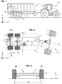
- FIG. 1 and 2 it shows a set formed by a tractor TR and a trailer 1 attached to the tractor.
- the X direction corresponds to the longitudinal axis
- the Y direction corresponds to the transverse axis
- the Z direction corresponds to the vertical axis.
- the yaw movement is a rotation around the vertical axis while the roll movement is a rotation around the longitudinal axis X.
- the yaw movement is a rotation around the vertical axis while the roll movement is a rotation around the longitudinal axis X.
- the axis marked XR corresponds to the longitudinal axis of the trailer while XT corresponds to the longitudinal axis of the tractor TR.
- the orientation of the longitudinal axis XR of the trailer relative to a local terrestrial reference point is noted ⁇ .
- ⁇ is the heading of the longitudinal axis of the trailer in the local terrestrial reference point.
- the trailer consists of a 11 chassis and a 10 drawbar.
- the trailer 1 illustrated here comprises two axles, E1 and E2 , with the first axle E1 having steered wheels and the second axle E2 having non-steered wheels. As will be seen later, the number of axles can be greater.
- the trailer carries 12 wheels, the center distance ER between the center planes of wheels of an axle represents the track of the axle (cf. Fig 3 ).
- Each axle comprises a main axle body 13 , connected to the chassis by a suspension system and longitudinal force absorption connecting rods.
- the axis of the main axle body Y2 coincides with the axis of rotation of the wheels of this axle.
- an articulation For an axle with steered wheels such as the first E1 here, at both ends of the main axle body 13 is provided an articulation with a substantially vertical axis. This articulation forms the pivoting mounting of a steering knuckle relative to the main axle body (axes Vg and Vd on the figure 3 ).
- a wheel hub is mounted on this stub axle to rotate.
- the hub and the stub axle have a rotatable horizontal axis (respectively marked W1g and W1d for the left rear and right rear wheels).
- each wheel is independent.
- the axles in question are not motorized.
- a braking function (not shown in the figures) may be provided at each of the wheels of the axle in question.
- each of the stub axles comprises a steering control arm and an actuator is provided, anchored at one of its ends to the main axle body and connected at the other end, by a more or less complex connecting rod, to each of the two steering control arms of the stub axles.
- the geometry of the steering control rod may be such that the angles of the left and right wheel axes (W1g and W1d) diverge slightly as the deflection from the neutral position increases.
- the reader may refer, for example, to the concepts of steering drawing, such as the Jeantaud drawing.
- the system comprises an angle sensor 74 capable of providing a measurement of the angle ⁇ .
- this can be obtained by a position sensor of the cylinder rod output 3, information which is then converted into an orientation angle ⁇ of the steered wheel by a calculation.
- the angle sensor 74 is for example installed at the level of the steering knuckle of one of the wheels of the axle in question.
- the rod 30 of the cylinder selectively pushes and pulls connecting rods connected to the control arms of the steering knuckles in order to modify the orientation of the steering wheels.
- each of the wheel sensors is formed as a dual wheel sensor that provides two quadrature signals.
- Future development could also be the taking of speed information directly from the tractor (+also with isobus) (taken into account elsewhere).
- the yaw motion sensor 2 is in the illustrated example a gyrometer comprising at least a first axis of interest, said first axis of interest being oriented horizontally relative to the chassis of the trailer, thus forming the yaw motion sensor.
- the gyrometer can be an organ measuring rotation along the 3 axes of space in which case it is a 3-axis gyrometer.
- the gyrometer can be an organ measuring rotation along the 3 axes of space and accelerations along the 3 axes of space in which case it is a so-called 6-axis accelerometer/gyrometer.
- the gyrometer 2 comprises at least a second axis of interest, said second axis of interest being oriented vertically relative to the trailer chassis, thus forming the roll motion sensor.
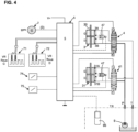
- the tractor provides a hydraulic pressure function.
- a pressurized hydraulic line marked P and a return line marked T (return line) called "double-acting supply" in the jargon are provided.
- a hydraulic pump marked 9 is also provided.
- a third hydraulic line called “Load sensing” is provided which makes it possible to modulate the production of hydraulic pressure according to the flow rate requirement of the systems present on the trailer, in particular the system for controlling the orientation of the steered wheels.
- the control system further comprises at least one distributor 4 called the first distributor.
- This distributor is functionally interposed between, on the one hand, the hydraulic pressure line P and the return line T , and on the other hand, the two end ports 3A , 3B of the double-acting cylinder.
- the distributor 4 is of the proportional control type.
- the flow rate depends on the current passing through the coils, as known per se, therefore not detailed here.
- a return by elastic member to the middle rest position is provided.
- the distributor slide is moved to the right or left under the effect of the current in the coils as known per se, allowing more or less oil to pass in one direction or the other direction respectively.
- FIG. 4 shows the elements for controlling a second axle with steered wheels E3 .
- a second cylinder 31 is provided for rotating the wheel stub axles.
- This second cylinder is also double-acting, and is controlled by a second distributor 41 similar to the first distributor.
- the second cylinder 31 has a first orifice 31A at one end and a second orifice 31B at the other end.
- the second steered axle E3 is identical or similar to the first steered axle, therefore not described again here.
- ⁇ 2 The angle made by the orientation of the wheels of the second steered axle E3 relative to the straight line is noted ⁇ 2 also called second angle.
- An angle sensor 75 is for example implanted at the level of the stub axle of one of the wheels of the axle E3 in question.
- the angle sensor 75 is capable of providing a measurement of the angle ⁇ 2 .
- the second angle ⁇ 2 is controlled via the second cylinder 31 by the electrohydraulic control unit 5.
- a user console 95 is provided arranged in the tractor cab.
- the user console 95 is used by a tractor operator to select one or more operating modes of the steered axle system, in particular to carry out manual or special commands.
- the control unit 5 is responsible for continuously determining a target steering angle ⁇ c for the first steered axle and, if necessary, a second steering angle ⁇ 2c for the second steered axle.
- control unit 5 determines the longitudinal speed VR . If there is only one sensor, it is the direct information from this sensor that is considered as the longitudinal speed VR.
- the control unit 5 determines, based on the information sent back by the angle sensor 74 , the current value of the angle ⁇ .
- the control unit 5 acquires from the yaw motion sensor a measurement of the yaw motion ( ⁇ ).
- control unit 5 calculates a target value for the first angle, such that the first angle ⁇ is made dependent at least on the yaw motion and the longitudinal speed.
- the function G (d ⁇ /dt , VRa) is a monotonic function over the entire range of yaw movements.
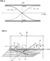
- G(d ⁇ /dt, VRa) we can choose G(d ⁇ /dt, VRa) as a linear function and thus obtain a substantially proportional control. But in the example illustrated in figure 5 , the G function is not linear, the slope decreases as we move away from the point 0,0. On the ordinate axis, ⁇ max and - ⁇ max represent the maximum orientation angular stops of the wheels of the axle.
- a typical route is illustrated from position P0 to position P5 and back to position P0 for a forward movement only with a first turn ( P2 , P3 ) and a second turn (P4) in the opposite direction.
- the function G includes a neutral zone ZN around the zero speed, and in this neutral zone, the control is such that the first angle ⁇ is kept intact without change, said neutral zone being defined by a low threshold VRb, and the neutral zone being between -VRb and +VRb.
- VRa corresponds to a speed outside the neutral zone ZN namely in equation on the absolute values
- the dashed curve 98 illustrates a route (S0-S1-S2-S3) on a curve where the speed reduces to 0, then reverse gear is engaged, still on the same curve (we change district in the map by crossing the neutral zone).
- FIG 8 illustrates in the form of a block diagram the control loop, with first the calculation of the target angle and then the control of the cylinder so as to cancel an error ⁇ c - ⁇ .
- the trailer may have at least one hydraulically suspended axle (with or without steered wheels).
- the steering system then includes an autonomous trim control function.
- the steering system further comprises a roll motion sensor providing an instantaneous measurement of the roll motion ( ⁇ ).
- the gyrometer comprises a second axis of interest, said second axis of interest being oriented vertically relative to the chassis of the trailer, thus forming the roll motion sensor.
- the control system comprises a left cylinder 61 and a right cylinder 62 for each axle concerned.
- the electrohydraulic control unit 5 controls the left and right cylinders to keep the chassis 11 substantially horizontal, even on sloping terrain.
- the angle between the transverse direction Y4 of the chassis and the direction Y1 of the main axle body is denoted ⁇ .
- This level correction (and tilt) function ensures a horizontal position of the trailer and in particular of its bucket for harvesting situations where the bucket receives a flow of material from another harvesting machine.
- This feature is also useful when cornering on the road, especially when going through roundabouts, where it is best to avoid the trailer leaning outwards.
- the left cylinder 61 and the right cylinder 62 are connected to a distributor 81 of the type already described for steering control.
- a bypass valve marked 48 is provided to leave the suspension floating.
- the two cylinders of the same axle are controlled by two hydraulic lines, a first hydraulic line connected to end A of the first cylinder on the left and to end B of the cylinder on the right, while the second hydraulic line connected to end B of the first cylinder on the left and to end A of the cylinder on the right.
- the gyrometer can be positioned on the chassis near the general center of gravity of the trailer as shown in figure 1 . According to another embodiment, the gyrometer is located at the front of the trailer near the housing which contains the control unit 5 .
- the hydraulic pressure is provided by an existing hydraulic pump on the tractor. It should be noted, however, that it is also possible to imagine a hydraulic unit on board the trailer with an electrical power supply from the tractor (the trailer is then autonomous from a hydraulic point of view).
- angles ⁇ and, where applicable, ⁇ 2 can be controlled so that the trailer moves crab-style; this is a special mode selected on the user console 95 .
Landscapes
- Engineering & Computer Science (AREA)
- Chemical & Material Sciences (AREA)
- Combustion & Propulsion (AREA)
- Transportation (AREA)
- Mechanical Engineering (AREA)
- Steering Control In Accordance With Driving Conditions (AREA)
Priority Applications (1)
| Application Number | Priority Date | Filing Date | Title |
|---|---|---|---|
| EP23167392.2A EP4446201A1 (de) | 2023-04-11 | 2023-04-11 | Selbstlenkender selbstlenkender achsanhänger |
Applications Claiming Priority (1)
| Application Number | Priority Date | Filing Date | Title |
|---|---|---|---|
| EP23167392.2A EP4446201A1 (de) | 2023-04-11 | 2023-04-11 | Selbstlenkender selbstlenkender achsanhänger |
Publications (1)
| Publication Number | Publication Date |
|---|---|
| EP4446201A1 true EP4446201A1 (de) | 2024-10-16 |
Family
ID=86006538
Family Applications (1)
| Application Number | Title | Priority Date | Filing Date |
|---|---|---|---|
| EP23167392.2A Withdrawn EP4446201A1 (de) | 2023-04-11 | 2023-04-11 | Selbstlenkender selbstlenkender achsanhänger |
Country Status (1)
| Country | Link |
|---|---|
| EP (1) | EP4446201A1 (de) |
Cited By (1)
| Publication number | Priority date | Publication date | Assignee | Title |
|---|---|---|---|---|
| US20240166257A1 (en) * | 2021-04-08 | 2024-05-23 | Scania Cv Ab | Control device and method for controlling a tag axle steering system |
Citations (6)
| Publication number | Priority date | Publication date | Assignee | Title |
|---|---|---|---|---|
| US5289892A (en) * | 1990-09-26 | 1994-03-01 | Nissan Diesel Motor Co., Ltd. | Steerable trailer and steering apparatus of combination vehicle |
| FR2909632A1 (fr) | 2006-12-07 | 2008-06-13 | Monroc | Procede et dispositif de commande des roues directrices d'une remorque. |
| WO2015010671A1 (de) | 2013-07-23 | 2015-01-29 | Friedhelm Hilken | Nachlaufachse mit zwangslenkung |
| DE102019006684A1 (de) * | 2019-09-24 | 2021-03-25 | HYDAC Software GmbH | Verfahren und Vorrichtung zum optimierten Nachführen eines mehrachsigen Anhängers hinter einem Zugfahrzeug |
| US20220042280A1 (en) * | 2018-12-27 | 2022-02-10 | Kubota Corporation | Work Vehicle |
| US20230036670A1 (en) * | 2021-07-27 | 2023-02-02 | Caterpillar Lnc. | Telehandler and method |
-
2023
- 2023-04-11 EP EP23167392.2A patent/EP4446201A1/de not_active Withdrawn
Patent Citations (6)
| Publication number | Priority date | Publication date | Assignee | Title |
|---|---|---|---|---|
| US5289892A (en) * | 1990-09-26 | 1994-03-01 | Nissan Diesel Motor Co., Ltd. | Steerable trailer and steering apparatus of combination vehicle |
| FR2909632A1 (fr) | 2006-12-07 | 2008-06-13 | Monroc | Procede et dispositif de commande des roues directrices d'une remorque. |
| WO2015010671A1 (de) | 2013-07-23 | 2015-01-29 | Friedhelm Hilken | Nachlaufachse mit zwangslenkung |
| US20220042280A1 (en) * | 2018-12-27 | 2022-02-10 | Kubota Corporation | Work Vehicle |
| DE102019006684A1 (de) * | 2019-09-24 | 2021-03-25 | HYDAC Software GmbH | Verfahren und Vorrichtung zum optimierten Nachführen eines mehrachsigen Anhängers hinter einem Zugfahrzeug |
| US20230036670A1 (en) * | 2021-07-27 | 2023-02-02 | Caterpillar Lnc. | Telehandler and method |
Cited By (2)
| Publication number | Priority date | Publication date | Assignee | Title |
|---|---|---|---|---|
| US20240166257A1 (en) * | 2021-04-08 | 2024-05-23 | Scania Cv Ab | Control device and method for controlling a tag axle steering system |
| US12473021B2 (en) * | 2021-04-08 | 2025-11-18 | Scania Cv Ab | Control device and method for controlling a tag axle steering system |
Similar Documents
| Publication | Publication Date | Title |
|---|---|---|
| EP1896315B1 (de) | Fahrassistenzverfahren für das rückwärts parken eines fahrzeugs mit anhänger | |
| EP1896314B1 (de) | Verfahren zur steuerung des lenkwinkels der führungsräder eines fahrzeugs | |
| US8380416B2 (en) | Method and apparatus for controlling brake-steer in an automotive vehicle in reverse | |
| US7401871B2 (en) | Method of controlling an automotive vehicle having a trailer using rear axle slip angle | |
| US7950751B2 (en) | Method and apparatus for maintaining a trailer in a straight position relative to the vehicle | |
| US8775048B2 (en) | Method and apparatus for determining a reference vehicle velocity and a rear wheel speed in a vehicle having three speed sensors | |
| US6959970B2 (en) | Method and apparatus for controlling a trailer and an automotive vehicle with a yaw stability control system | |
| US7401870B2 (en) | Method and apparatus to enhance brake-steer of a vehicle using a controllable suspension component | |
| US7165644B2 (en) | Method and apparatus of controlling an automotive vehicle using brake-steer as a function of steering wheel torque | |
| US7070247B2 (en) | Method and apparatus for controlling brake-steer in an automotive vehicle in a forward and reverse direction | |
| US20050206231A1 (en) | Method and apparatus for controlling an automotive vehicle using brake-steer and normal load adjustment | |
| US20060076828A1 (en) | Utility vehicle using brake-steer assisted turning | |
| US20050206225A1 (en) | Method and apparatus for predicting the position of a trailer relative to a vehicle | |
| US20050209762A1 (en) | Method and apparatus for controlling a vehicle using an object detection system and brake-steer | |
| WO2007000502A1 (fr) | Procede de determination d'une consigne d'angle de braquage des roues directrices d'un vehicule | |
| WO2014135310A1 (fr) | Vehicule automobile routier attelable | |
| FR2775773A1 (fr) | Procede et dispositif de determination de l'empattement de vehicule | |
| CA2865764A1 (fr) | Remorque routiere a train de roulage secondaire orientable | |
| ES2982712T3 (es) | Procedimiento y dispositivo para optimizar el seguimiento de un remolque de varios ejes detrás de un vehículo tractor | |
| EP4446201A1 (de) | Selbstlenkender selbstlenkender achsanhänger | |
| EP4444600B1 (de) | Fahrzeugzug und lenkungssteuersystem für einen solchen zug | |
| CN116639181A (zh) | 用于车辆的扭矩矢量控制方法 | |
| GB2435023A (en) | Differentially drivable vehicle having parking mode determination and turning radius reduction | |
| EP3523179B1 (de) | Anpassung der einstellungen einer elektrischen servolenkung | |
| EP0927678A1 (de) | Automatisches Bahnkorrektursystem eines Fahrbahnstörungen oder Seitenwind unterworfenen Fahrzeugs |
Legal Events
| Date | Code | Title | Description |
|---|---|---|---|
| PUAI | Public reference made under article 153(3) epc to a published international application that has entered the european phase |
Free format text: ORIGINAL CODE: 0009012 |
|
| STAA | Information on the status of an ep patent application or granted ep patent |
Free format text: STATUS: THE APPLICATION HAS BEEN PUBLISHED |
|
| AK | Designated contracting states |
Kind code of ref document: A1 Designated state(s): AL AT BE BG CH CY CZ DE DK EE ES FI FR GB GR HR HU IE IS IT LI LT LU LV MC ME MK MT NL NO PL PT RO RS SE SI SK SM TR |
|
| STAA | Information on the status of an ep patent application or granted ep patent |
Free format text: STATUS: THE APPLICATION IS DEEMED TO BE WITHDRAWN |
|
| 18D | Application deemed to be withdrawn |
Effective date: 20250417 |