EP4446171A1 - Improved go-kart with protection assembly - Google Patents
Improved go-kart with protection assembly Download PDFInfo
- Publication number
- EP4446171A1 EP4446171A1 EP24170042.6A EP24170042A EP4446171A1 EP 4446171 A1 EP4446171 A1 EP 4446171A1 EP 24170042 A EP24170042 A EP 24170042A EP 4446171 A1 EP4446171 A1 EP 4446171A1
- Authority
- EP
- European Patent Office
- Prior art keywords
- frame
- ring bodies
- impact
- kart
- containment structure
- Prior art date
- Legal status (The legal status is an assumption and is not a legal conclusion. Google has not performed a legal analysis and makes no representation as to the accuracy of the status listed.)
- Granted
Links
Images


Classifications
-
- B—PERFORMING OPERATIONS; TRANSPORTING
- B60—VEHICLES IN GENERAL
- B60R—VEHICLES, VEHICLE FITTINGS, OR VEHICLE PARTS, NOT OTHERWISE PROVIDED FOR
- B60R19/00—Wheel guards; Radiator guards, e.g. grilles; Obstruction removers; Fittings damping bouncing force in collisions
- B60R19/02—Bumpers, i.e. impact receiving or absorbing members for protecting vehicles or fending off blows from other vehicles or objects
- B60R19/42—Bumpers, i.e. impact receiving or absorbing members for protecting vehicles or fending off blows from other vehicles or objects extending primarily along the sides of, or completely encircling, a vehicle
-
- A—HUMAN NECESSITIES
- A63—SPORTS; GAMES; AMUSEMENTS
- A63G—MERRY-GO-ROUNDS; SWINGS; ROCKING-HORSES; CHUTES; SWITCHBACKS; SIMILAR DEVICES FOR PUBLIC AMUSEMENT
- A63G25/00—Autocar-like self-drivers; Runways therefor
Definitions
- the present disclosure relates generally to an improved go-kart.
- the present disclosure concerns an improved go-kart comprising a protection assembly.
- the safety of the driver and the vehicle requires the use of protection means, in particular to at least partially absorb the energy of any collision or impact while driving the go-kart.
- karts such as those made available so far by the prior art, although advantageous from many points of view, involve a transfer of the energy of collisions and impacts to the frame of the kart.
- known devices only allow to absorb vibrations while driving the kart but allow the transmission of impact energy to the frame.
- karts according to the known art generally have a heavy structure to favour the absorption of vibrations. This leads to high consumption of fuel and of the tires of the kart due to the high weight.
- the present disclosure starts from the position of the technical problem of providing a kart that allows to meet the above-mentioned needs with reference to the known art and/or to achieve further advantages.
- a go-kart comprising a frame having an external impact surface, suitable for facing an impact.
- the go-kart also includes a protection assembly to protect the frame, wherein the protection assembly includes:
- the protection assembly further includes fastening means for fastening each of the plurality of ring bodies to the containment structure and for fastening each of the plurality of ring bodies to the frame.
- each of the plurality of ring bodies is arranged between the external surface and the containment structure.
- each of the plurality of ring bodies is configured to be subjected to a deformation in the event of an impact.
- the frame has a front zone, a rear zone and two side zones, the ring bodies are arranged along the front zone and/or along the rear zone of the frame and/or along at least one of the side zones.
- the containment structure is a continuous body that wraps the frame along the front zone, the rear zone and the two side zones. This means that the containment structure presents structural continuity, i.e. it develops along a continuous line without corners or edges, both in the case that it is made up of a single piece and in the case that it is made up of several parts connected to each other. In other words, the containment structure forms a continuous and unfragmented line, even if made up of one or more parts connected to each other.
- the containment structure can be a closed line or substantially oval.
- the containment structure is a continuous body that wraps the frame and is associated with each of the plurality of ring bodies in a tangential manner.
- an embodiment of a go-kart according to the present invention is indicated overall with the reference number 100.
- the go-kart comprises a frame 10 having an external impact surface 11, i.e. capable of facing an impact or a collision, and a protection assembly 20 to protect the frame 10.
- the protection assembly comprises:
- the protection assembly 20 further includes fastening means for fastening each of the plurality of ring bodies 21a, 21b, 21c to the containment structure 22 and for fastening each of the plurality of ring bodies 21a, 21b, 21c to the frame 10.
- fastening means are configured to connect in a fixed or rigid manner each of the plurality of ring bodies 21a, 21b, 21c both to the containment structure 22 and to the frame 10, for example by tightening preferably by means of a bolt.
- each of the plurality of ring bodies 21a, 21b, 21c is configured to be subjected to a deformation in the event of an impact.
- each of the plurality of ring bodies 21a, 21b, 21c is positioned along the external surface 11 of the frame 10 and is at least partially wrapped or contained by the containment structure 22, for example along a region opposite the external surface 11.
- each of the plurality of ring bodies 21a, 21b, 21c is configured to be able to assume a rest condition and a deformed condition.
- each of the plurality of ring bodies 21a, 21b, 21c is preferably configured to be subjected to a temporary deformation and assume said deformed condition.
- each of the plurality of ring bodies 21a, 21b, 21c is configured to assume the initial or rest condition in a condition of absence of impact or shock.
- each of the plurality of ring bodies 21a, 21b, 21c is configured to move from the rest condition to the deformed condition, and preferably is further configured to return to the rest condition at the end of the collision or impact.
- each of the plurality of ring bodies 21a, 21b, 21c can at least partially absorb an impact energy due to an impact of the go-kart.
- each of the plurality of ring bodies 21a, 21b, 21c is shaped like a hollow cylinder or tubular body comprising two hollow base surfaces and a lateral surface.
- each of the plurality of ring bodies 21a, 21b, 21c is associated with the frame 10, along the external surface 11, and with the containment structure 22 along the lateral surface of the hollow cylinder or tubular body.
- each of the plurality of ring bodies 21a, 21b, 21c is configured to deform in the event of impacts mainly along at least one direction perpendicular to an axis of the hollow cylinder or tubular body. That is to say that in the event of an impact along a direction parallel to the axis of the hollow cylinder or tubular body the deformation of each of the plurality of ring bodies 21a, 21b, 21c is preferably zero or negligible.
- each of the plurality of ring bodies 21a, 21b, 21c involves a change in the shape and/or area of the hollow base surfaces of the hollow cylinder or tubular body.
- the deformation of each of the plurality of ring bodies 21a, 21b, 21c involves a zero or negligible variation in the height of the hollow cylinder or tubular body.
- the protection assembly 20 includes a plurality of ring bodies 21a, 21b and the containment structure 22 is associated with each of the plurality of ring bodies 21a, 21b in a tangent manner.
- the containment structure 22 touches in a tangent manner each of the ring bodies of the plurality of ring bodies 21a, 21b.
- the frame 10 has a front zone 10a, a rear zone 10b and two side zones 10c. Furthermore, each of the plurality of ring bodies 21a, 21b, 21c is arranged along the front zone 10a and/or along the rear zone 10b of the frame 10 and/or in at least one of the two side zones 10c. This means that the plurality of ring bodies 21a, 21b, 21c are preferably positioned along the external surface 11 of the frame 10 in correspondence of or close to the front zone 10a, and/or in correspondence of or close to the rear zone 10b of the frame 10, and/or in correspondence of or close to one or both side zones (10c).
- each of the plurality of ring bodies 21a, 21b, 21c can be positioned in correspondence with or close to one or more of the zones of the frame 10, i.e. the front zone 10a, the rear zone 10b and the side zones 10c. It is clear that a plurality of ring bodies 21a, 21b, 21c are preferably provided in such a way as to at least partially occupy each of the zones of the frame 10 provided with at least one ring body 21a, 21b, 21c.
- front zone 10a and the rear zone 10b are the zones most frequently subject to impacts, so it is advantageous to position the ring bodies 21a, 21b along at least one of the two, but it is possible to position the ring bodies 21a, 21b also along the side zones 10c of the frame 10.
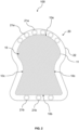
- the protection assembly 20 includes five ring bodies 21a arranged along the front zone 10a of the frame 10 and three ring bodies 21b arranged along the rear zone 10b of the frame 10, as shown in Figure 2 .
- the protection assembly 20 further comprises a ring body 21c arranged along one of the side zones 10c of the frame 10 and a ring body 21c arranged along the other of the side zones 10c of the frame 10.
- the go-kart according to the present invention can present five ring bodies 21a along the front zone 10a, three ring bodies 21b along the rear zone 21b and one ring body 21c along each of the two side zones 10c.
- the containment structure 22 is a continuous body that wraps the frame 10 along the front zone 10a, the rear zone 10b and the two side zones 10c. That is to say that the containment structure 22 preferably wraps the entire frame 10 along the external surface 11 and contains at least one ring body 21a, 21b close to the external surface 11.
- containment structure 22 is a continuous body in the sense that it presents structural continuity and that it can be formed by one or more parts connected to each other.
- the containment structure 22 is a continuous structure without hinges. That is to say, the containment structure 22 forms a structure that preferably acts as a rigid body.
- This configuration allows the energy of an impact to be dissipated through one or more ring bodies 21a, 21b, 21c closest to the point of impact.
- the one or more ring bodies 21a, 21b, 21c arranged along the zone or zones subjected to impact are deformed during the impact, while any one or more additional ring bodies 21a, 21b, 21c arranged along the zone or zones not subjected to impact remain in the rest condition during the impact, or are deformed to a lesser extent than the previous ones.
- This configuration therefore allows maximizing the dissipation of impact energy by each ring body 21a, 21b, 21c while at the same time allowing the kart to be protected from impacts along the entire external surface 11 of the frame 10.
- the containment structure 22 which envelops the entire frame 10 allows the energy of an impact to be transferred towards one or more ring bodies 21a, 21b closest to the point of impact, which can consequently dissipate the energy of an impact passing from the rest condition to the deformed condition, while any one or more additional ring bodies 21a, 21b distal from the impact point preferably remain in the rest condition during the impact.
- this configuration allows the energy of two or more simultaneous impacts in different areas of the kart to be effectively absorbed.
- each of the plurality of ring bodies 21a, 21b, 21c is made of elastic material.
- the at least one ring body 21a, 21b, 21c is made of rubber or a polymeric material with excellent shock absorption and elastic deformation capabilities.
- the containment structure 22 is also made of elastic material, for example the same material as the ring bodies 21a, 21b, 21c.
- the ring bodies 21a, 21b, 21c are the only connection between the containment structure 22 and the frame 10. That is to say that preferably only the ring bodies 21a, 21b, 21c and the fastening means are present between the containment structure 22 and the frame 10.
- each of the plurality of ring bodies 21a, 21b, 21c corresponds to or is equal to the distance between the containment structure 22 and the frame 10 in correspondence of each of the plurality of ring bodies 21a, 21b, 21c.
- each of the plurality of ring bodies 21a, 21b, 21c has an external diameter that coincides with the distance between the containment structure 22 and the frame 10 in the zone in which the respective ring of the plurality of ring bodies 21a, 21b, 21c is positioned.
- the present invention further relates to a method of impact protection for a go-kart 100 comprising a frame 10 having an external impact surface 11 suitable for facing an impact.
- the method involves the following phases:
- the at least one ring body 21a, 21b is configured to be able to assume a rest condition and a deformed condition.
- the at least one ring body 21a, 21b assumes the deformed condition and furthermore both before the temporary deformation and following the springback phase, the at least one ring body 21a, 21b assumes the rest condition.
- the at least one ring body 21a, 21b is in the rest condition and in the event of an impact or collision the at least one ring body 21a, 21b can assume the deformed condition to carry out the temporary deformation phase and absorb at least partially the collision or impact energy.
- the protection assembly 22 includes a plurality of ring bodies 21a, 21b.
- the containment structure 22 is a continuous body that envelops the frame 10 and is associated with each of the plurality of ring bodies 21a, 21b in a tangential manner. This means that the containment structure 22 touches in a tangential manner each of the ring bodies of the plurality of ring bodies 21a, 21b.
- the ring bodies arranged along the zone or zones subjected to impact are deformed during the impact, while preferably the ring bodies arranged along the zone or zones not subjected to impact remain in the rest condition during the impact, or they are deformed to a lesser extent than the previous ones.
- the protection assembly can at least partially absorb the energy of an impact or collision, thus guaranteeing an improved protection for the driver and the vehicle.
Landscapes
- Engineering & Computer Science (AREA)
- Mechanical Engineering (AREA)
- Superstructure Of Vehicle (AREA)
Abstract
- at least one ring body (21a, 21b) arranged along the external surface (11) of the frame (10);
- a containment structure (22) which surrounds the external surface (11) of the frame (10) and contains the at least one ring body (21a, 21b).
Description
- The present disclosure relates generally to an improved go-kart. In particular, the present disclosure concerns an improved go-kart comprising a protection assembly.
- In the go-kart sector, the safety of the driver and the vehicle requires the use of protection means, in particular to at least partially absorb the energy of any collision or impact while driving the go-kart.
- Generally, in karts according to the prior art, the use of rigid structures that favour the absorption of vibrations is envisaged. For example, the use of "silent blocks" is known, i.e. anti-vibration bushings capable of absorbing part of the vibrations generated while driving the kart.
- At the basis of the present disclosure there is a recognition by the inventor of the present disclosure that karts such as those made available so far by the prior art, although advantageous from many points of view, involve a transfer of the energy of collisions and impacts to the frame of the kart.
- This poses a risk to the safety of the driver and the vehicle since the energy of the impacts is transmitted to the driver's body and to the kart frame, causing injuries and/or damage, respectively.
- Specifically, known devices only allow to absorb vibrations while driving the kart but allow the transmission of impact energy to the frame.
- In addition, a further recognition by the inventor of the present disclosure consists in the fact that the karts according to the known art generally have a heavy structure to favour the absorption of vibrations. This leads to high consumption of fuel and of the tires of the kart due to the high weight.
- The present disclosure starts from the position of the technical problem of providing a kart that allows to meet the above-mentioned needs with reference to the known art and/or to achieve further advantages.
- This is achieved by a go-kart comprising a protection assembly and an impact protection method for a go-kart according to the respective independent claims. Secondary features of the subject matter of the present disclosure are defined in the corresponding dependent claims.
- In particular, in accordance with the present disclosure, in order to improve the kart according to the prior art, it is proposed to improve the protection assembly against shocks and impacts.
- For this purpose, it is proposed to create a go-kart comprising a frame having an external impact surface, suitable for facing an impact. The go-kart also includes a protection assembly to protect the frame, wherein the protection assembly includes:
- a plurality of ring bodies arranged along the external surface of the frame;
- a containment structure that surrounds the external surface of the frame and contains the plurality of ring bodies. In particular, the containment structure is associated with each of the plurality of ring bodies in a tangential manner.
- Furthermore, the protection assembly further includes fastening means for fastening each of the plurality of ring bodies to the containment structure and for fastening each of the plurality of ring bodies to the frame.
- Furthermore, each of the plurality of ring bodies is arranged between the external surface and the containment structure. In particular, each of the plurality of ring bodies is configured to be subjected to a deformation in the event of an impact.
- Furthermore, the frame has a front zone, a rear zone and two side zones, the ring bodies are arranged along the front zone and/or along the rear zone of the frame and/or along at least one of the side zones. Furthermore, the containment structure is a continuous body that wraps the frame along the front zone, the rear zone and the two side zones. This means that the containment structure presents structural continuity, i.e. it develops along a continuous line without corners or edges, both in the case that it is made up of a single piece and in the case that it is made up of several parts connected to each other. In other words, the containment structure forms a continuous and unfragmented line, even if made up of one or more parts connected to each other. For example, the containment structure can be a closed line or substantially oval.
- Furthermore, according to the present disclosure it is made available a method of impact protection for a go-kart comprising a frame having an external impact surface adapted to face an impact. The method involves the following phases:
- providing a protection assembly configured to protect the frame, wherein the protection assembly includes a plurality of ring bodies, arranged along the external surface of the frame, and a containment structure, which surrounds the external surface, wherein each of the plurality of ring bodies is arranged between the external surface and the containment structure;
- a temporary deformation of each of the plurality of ring bodies in the event of an impact, in such a way as to at least partially absorb an impact energy;
- a springback of each of the plurality of ring bodies at the end of the impact.
- In particular, according to the method the containment structure is a continuous body that wraps the frame and is associated with each of the plurality of ring bodies in a tangential manner.
- Further advantages, characteristics and methods of use of the subject matter of the present disclosure will be evident from the following detailed description of its embodiments, presented for illustrative and non-limiting purposes.
- It is however clear that each embodiment of the subject matter of the present disclosure can present one or more of the advantages listed above; in any case it is not required that each embodiment simultaneously presents all the advantages listed.
- Reference will be made to the figures in the attached drawings, wherein:
-
Figure 1 shows a schematic top view of a go-kart according to a first embodiment of the present invention; -
Figure 2 shows a schematic top view of a go-kart according to an alternative embodiment of the present invention; -
Figure 3 shows a top view of a front area of a go-kart according to the embodiment ofFigure 1 . - With reference to the attached figures, an embodiment of a go-kart according to the present invention is indicated overall with the
reference number 100. - The go-kart comprises a
frame 10 having anexternal impact surface 11, i.e. capable of facing an impact or a collision, and aprotection assembly 20 to protect theframe 10. In particular, the protection assembly comprises: - a plurality of
ring bodies external surface 11 of theframe 10; - a
containment structure 22 which surrounds theexternal surface 11 of theframe 10 and contains each of the plurality ofring bodies ring bodies external surface 11 andcontainment structure 20. - Furthermore, the
protection assembly 20 further includes fastening means for fastening each of the plurality ofring bodies containment structure 22 and for fastening each of the plurality ofring bodies frame 10. This means that the fastening means are configured to connect in a fixed or rigid manner each of the plurality ofring bodies containment structure 22 and to theframe 10, for example by tightening preferably by means of a bolt. - In particular, each of the plurality of
ring bodies - In other words, each of the plurality of
ring bodies external surface 11 of theframe 10 and is at least partially wrapped or contained by thecontainment structure 22, for example along a region opposite theexternal surface 11. - Preferably, each of the plurality of
ring bodies ring bodies ring bodies ring bodies - In this way, through elastic deformation each of the plurality of
ring bodies - According to one embodiment, each of the plurality of
ring bodies ring bodies frame 10, along theexternal surface 11, and with thecontainment structure 22 along the lateral surface of the hollow cylinder or tubular body. - Preferably therefore each of the plurality of
ring bodies ring bodies - In other words, in the event of impact preferably the deformation of each of the plurality of
ring bodies ring bodies - According to the invention, the
protection assembly 20 includes a plurality ofring bodies containment structure 22 is associated with each of the plurality ofring bodies - That is to say that preferably the
containment structure 22 touches in a tangent manner each of the ring bodies of the plurality ofring bodies - According to the invention, the
frame 10 has afront zone 10a, arear zone 10b and twoside zones 10c. Furthermore, each of the plurality ofring bodies front zone 10a and/or along therear zone 10b of theframe 10 and/or in at least one of the twoside zones 10c. This means that the plurality ofring bodies external surface 11 of theframe 10 in correspondence of or close to thefront zone 10a, and/or in correspondence of or close to therear zone 10b of theframe 10, and/or in correspondence of or close to one or both side zones (10c). - In other words, preferably each of the plurality of
ring bodies frame 10, i.e. thefront zone 10a, therear zone 10b and theside zones 10c. It is clear that a plurality ofring bodies frame 10 provided with at least onering body front zone 10a and therear zone 10b are the zones most frequently subject to impacts, so it is advantageous to position thering bodies ring bodies side zones 10c of theframe 10. - Advantageously and preferably, the
protection assembly 20 includes fivering bodies 21a arranged along thefront zone 10a of theframe 10 and threering bodies 21b arranged along therear zone 10b of theframe 10, as shown inFigure 2 . - Even more preferably, the
protection assembly 20 further comprises aring body 21c arranged along one of theside zones 10c of theframe 10 and aring body 21c arranged along the other of theside zones 10c of theframe 10. - Therefore, according to a preferred embodiment shown in
Figure 1 , the go-kart according to the present invention can present fivering bodies 21a along thefront zone 10a, threering bodies 21b along therear zone 21b and onering body 21c along each of the twoside zones 10c. - It is clear that it is also possible to distribute along the
frame 10 a greater or lower number ofring bodies - According to the invention, the
containment structure 22 is a continuous body that wraps theframe 10 along thefront zone 10a, therear zone 10b and the twoside zones 10c. That is to say that thecontainment structure 22 preferably wraps theentire frame 10 along theexternal surface 11 and contains at least onering body external surface 11. - This means that the
containment structure 22 is a continuous body in the sense that it presents structural continuity and that it can be formed by one or more parts connected to each other. - Preferably, the
containment structure 22 is a continuous structure without hinges. That is to say, thecontainment structure 22 forms a structure that preferably acts as a rigid body. - This configuration allows the energy of an impact to be dissipated through one or
more ring bodies more ring bodies additional ring bodies ring body external surface 11 of theframe 10. - This means that the
containment structure 22 which envelops theentire frame 10 allows the energy of an impact to be transferred towards one ormore ring bodies additional ring bodies - For example, this configuration allows the energy of two or more simultaneous impacts in different areas of the kart to be effectively absorbed. This means that for example it is possible to dissipate the energy of a first impact through the deformation of a
ring body second ring body - Preferably, each of the plurality of
ring bodies ring body - Even more preferably, the
containment structure 22 is also made of elastic material, for example the same material as thering bodies - Preferably, the
ring bodies containment structure 22 and theframe 10. That is to say that preferably only thering bodies containment structure 22 and theframe 10. - Preferably, the external diameter of each of the plurality of
ring bodies containment structure 22 and theframe 10 in correspondence of each of the plurality ofring bodies ring bodies containment structure 22 and theframe 10 in the zone in which the respective ring of the plurality ofring bodies - The present invention further relates to a method of impact protection for a go-
kart 100 comprising aframe 10 having anexternal impact surface 11 suitable for facing an impact. The method involves the following phases: - providing a
protection assembly 20 configured to protect theframe 10, where theprotection assembly 20 includes at least aring body external surface 11 of theframe 10, and acontainment structure 22, which surrounds theexternal surface 11, where in particular the at least onering body external surface 11 and thecontainment structure 20; - a temporary deformation of the at least one
ring body - a springback of the at least one
ring body - Preferably, the at least one
ring body ring body ring body - This means that preferably in the absence of impacts or collisions the at least one
ring body ring body - Furthermore, according to the invention, the
protection assembly 22 includes a plurality ofring bodies containment structure 22 is a continuous body that envelops theframe 10 and is associated with each of the plurality ofring bodies containment structure 22 touches in a tangential manner each of the ring bodies of the plurality ofring bodies - Preferably only the ring bodies arranged along the zone or zones subjected to impact are deformed during the impact, while preferably the ring bodies arranged along the zone or zones not subjected to impact remain in the rest condition during the impact, or they are deformed to a lesser extent than the previous ones.
- It is therefore clear that a go-kart including the protection assembly described, as well as the impact protection method for a go-kart, allow the limits of the known art to be overcome in relation to the safety of the driver and to that of the vehicle.
- In particular, through a temporary deformation of the at least one
ring body - The object of the present disclosure has so far been described with reference to its embodiments. It is to be understood that there may be other embodiments that relate to the same inventive core, all falling within the scope of protection of the claims set out below.
Claims (12)
- Go-kart (100) comprising a frame (10) having an external impact surface (11) adapted to face an impact and a protection assembly (20) for protecting said frame (10), wherein the protection assembly comprises:- a plurality of ring bodies (21a, 21b, 21c) (21a, 21b, 21c) arranged along the external surface (11) of said frame (10);- a containment structure (22) which surrounds said external surface (11) of said frame (10) and contains said ring bodies (21a, 21b, 21c), said ring bodies (21a, 21b, 21c) being arranged between said external surface (11) and said containment structure (22), and wherein said containment structure (22) is associated with each of said plurality of ring bodies (21a, 21b, 21c) in a tangent manner, andwherein said protection assembly (20) further comprises fastening means for fastening each of said plurality of ring bodies (21a, 21b, 21c) to said containment structure (22) and for fastening each of said plurality of ring bodies (21a, 21b, 21c) to said frame (10),wherein each of said plurality of ring bodies (21a, 21b, 21c) (21a, 21b, 21c) is configured to be subjected to deformation in the event of an impact,wherein the frame has a front zone (10a), a rear zone (10b) and two side zones (10c), and wherein said plurality of ring bodies (21a, 21b, 21c) are arranged in said front zone (10a) and/or in said rear zone (10b) of the frame and/or in at least one of said side zones (10c) and wherein said containment structure (22) is a continuous body that wraps said frame (10) along said front zone (10a), said rear zone (10b) and said two side zones (10c).
- Go-kart (100) according to the preceding claim, wherein each of said plurality of ring bodies (21a, 21b, 21c) is configured to be able to assume a rest condition and a deformed condition, and wherein each of said plurality of ring bodies (21a, 21b, 21c) is configured to be subjected to a temporary deformation and assume said deformed condition in the event of an impact, and is configured to assume said initial or rest condition in a condition of absence of impact or collision.
- Go-kart (100) according to one of the preceding claims, wherein each of said plurality of ring bodies (21a, 21b, 21c) is shaped like a hollow cylinder or tubular body comprising two hollow base surfaces and a side surface, and wherein each of said plurality of ring bodies (21a, 21b, 21c) is associated with said frame (10) and with said containment structure (22) along said side surface.
- Go-kart (100) according to the preceding claim, wherein said protection assembly (20) includes five ring bodies (21a) arranged along said front zone (10a) of said frame (10) and three ring bodies (21b) arranged along said rear zone (10b) of said frame (10).
- Go-kart (100) according to the preceding claim, wherein said protection assembly further comprises a ring body (21c) arranged along one of said side zones (10c) of said frame (10) and a ring body (21c) arranged along the other of said side zones (10c) of said frame (10).
- Go-kart (100) according to one of the preceding claims, wherein each of said plurality of ring bodies (21a, 21b, 21c) is made of elastic material.
- Go-kart (100) according to one of the preceding claims, wherein said containment structure (22) is a continuous structure without hinges.
- Go-kart (100) according to one of the preceding claims, wherein said ring bodies (21a, 21b, 21c) are the only connection between said containment structure (22) and said frame (10).
- Go-kart (100) according to one of the preceding claims, wherein the external diameter of each of said plurality of ring bodies (21a, 21b, 21c) corresponds to or is equal to the distance between said containment structure (22) and said frame (10) in correspondence of said each of said plurality of ring bodies (21a, 21b, 21c).
- Go-kart (100) according to one of the preceding claims, wherein said fastening means are configured to fasten each of said plurality of ring bodies (21a, 21b, 21c) to said containment structure (22) and to said frame (10) by tightening.
- Impact protection method for a go-kart (100) comprising a frame (10) having an external impact surface (11) adapted to face an impact, wherein said method involves the following steps:- providing a protection assembly (20) configured to protect said frame (10), wherein the protection assembly (20) includes at least one ring body (21a, 21b, 21c), arranged along the external surface (11) of said frame (10), and a containment structure (22), which surrounds said external surface (11), wherein said at least one ring body (21a, 21b, 21c) is arranged between said external surface (11) and said containment structure (22),- a temporary deformation of said at least one ring body (21a, 21b, 21c) in the event of an impact in such a way as to at least partially absorb an impact energy,- a springback of said at least one ring body (21a, 21b, 21c) at the end of the impact,and wherein said protection assembly (20) comprises a plurality of ring bodies (21a, 21b, 21c) and wherein said containment structure (22) is a continuous body which wraps said frame (10) and is associated with each of said plurality of ring bodies (21a, 21b, 21c) in a tangent manner.
- Method according to the preceding claim, wherein each of said plurality of ring bodies (21a, 21b, 21c) is configured to be able to assume a rest condition and a deformed condition, wherein during said temporary deformation each of said plurality of ring bodies ring (21a, 21b, 21c) assumes said deformed condition and wherein before said temporary deformation and following said springback each of said plurality of ring bodies (21a, 21b, 21c) assumes said rest condition.
Applications Claiming Priority (1)
| Application Number | Priority Date | Filing Date | Title |
|---|---|---|---|
| IT102023000007146A IT202300007146A1 (en) | 2023-04-13 | 2023-04-13 | IMPROVED GO-KART WITH PROTECTION ASSEMBLY |
Publications (3)
| Publication Number | Publication Date |
|---|---|
| EP4446171A1 true EP4446171A1 (en) | 2024-10-16 |
| EP4446171C0 EP4446171C0 (en) | 2025-11-12 |
| EP4446171B1 EP4446171B1 (en) | 2025-11-12 |
Family
ID=86942557
Family Applications (1)
| Application Number | Title | Priority Date | Filing Date |
|---|---|---|---|
| EP24170042.6A Active EP4446171B1 (en) | 2023-04-13 | 2024-04-12 | Improved go-kart with protection assembly |
Country Status (2)
| Country | Link |
|---|---|
| EP (1) | EP4446171B1 (en) |
| IT (1) | IT202300007146A1 (en) |
Citations (5)
| Publication number | Priority date | Publication date | Assignee | Title |
|---|---|---|---|---|
| US1543462A (en) * | 1923-03-24 | 1925-06-23 | Vaszin Aurel | Amusement device |
| US5806901A (en) * | 1995-10-25 | 1998-09-15 | D.T. Motorsport Inc. | Bumper system |
| EP2808205A1 (en) * | 2013-05-27 | 2014-12-03 | TBKART S.r.l. | Go-kart provided with shock absorption means |
| DE202018100973U1 (en) * | 2017-02-27 | 2018-03-01 | Ford Global Technologies, Llc | Bumper arrangement |
| US20200017045A1 (en) * | 2018-07-12 | 2020-01-16 | Qiusheng Gao | Safe Protection Equipment for all vehicles and drivers |
-
2023
- 2023-04-13 IT IT102023000007146A patent/IT202300007146A1/en unknown
-
2024
- 2024-04-12 EP EP24170042.6A patent/EP4446171B1/en active Active
Patent Citations (5)
| Publication number | Priority date | Publication date | Assignee | Title |
|---|---|---|---|---|
| US1543462A (en) * | 1923-03-24 | 1925-06-23 | Vaszin Aurel | Amusement device |
| US5806901A (en) * | 1995-10-25 | 1998-09-15 | D.T. Motorsport Inc. | Bumper system |
| EP2808205A1 (en) * | 2013-05-27 | 2014-12-03 | TBKART S.r.l. | Go-kart provided with shock absorption means |
| DE202018100973U1 (en) * | 2017-02-27 | 2018-03-01 | Ford Global Technologies, Llc | Bumper arrangement |
| US20200017045A1 (en) * | 2018-07-12 | 2020-01-16 | Qiusheng Gao | Safe Protection Equipment for all vehicles and drivers |
Also Published As
| Publication number | Publication date |
|---|---|
| EP4446171C0 (en) | 2025-11-12 |
| IT202300007146A1 (en) | 2024-10-13 |
| EP4446171B1 (en) | 2025-11-12 |
Similar Documents
| Publication | Publication Date | Title |
|---|---|---|
| US4961603A (en) | Vehicle bumper system | |
| KR102182842B1 (en) | Vehicle body anti-collision structure | |
| KR20190136688A (en) | Safety barrier | |
| EP4446171B1 (en) | Improved go-kart with protection assembly | |
| WO2008108597A1 (en) | Crash box for an automobile | |
| KR100440855B1 (en) | A bumper of automobile | |
| KR101523851B1 (en) | Front side member with collision avoidance structure for vehicle | |
| KR100501237B1 (en) | Vehicle bumper for protecting pedestrian | |
| KR910002609Y1 (en) | Shock absorbing frame for vehicle | |
| KR20090112796A (en) | Bumper Stays for Cars | |
| KR20050015333A (en) | Bumper Back Beam for a Vehicle | |
| CN208855572U (en) | Automobile buffer beam and automobile | |
| KR200242749Y1 (en) | The Median strip of safety cover structure | |
| KR100482965B1 (en) | A bumper for vehicle | |
| CN121291314A (en) | A protective bracket for the front of the driver's cab and the vehicle | |
| KR100265965B1 (en) | Shock Absorber of Vehicle Front Pillar Trim | |
| KR100250279B1 (en) | Reinforcing structure for offset crash of a car | |
| KR100371234B1 (en) | Bumper for vehicle | |
| KR890005280Y1 (en) | Car frame structure | |
| KR970003659Y1 (en) | A longitudinal member of space frame for impact damping in the automobile | |
| KR100441448B1 (en) | Automobile Time-Sequenced Impact Absorbing System | |
| EP3505424B1 (en) | Kart | |
| KR20200089243A (en) | Median Strip Having Impact Absorption Part | |
| KR20110093981A (en) | Vehicle front collision energy absorber having a plurality of collision energy absorption stages | |
| KR19990025938U (en) | Cushioning frame of vehicle |
Legal Events
| Date | Code | Title | Description |
|---|---|---|---|
| PUAI | Public reference made under article 153(3) epc to a published international application that has entered the european phase |
Free format text: ORIGINAL CODE: 0009012 |
|
| STAA | Information on the status of an ep patent application or granted ep patent |
Free format text: STATUS: THE APPLICATION HAS BEEN PUBLISHED |
|
| AK | Designated contracting states |
Kind code of ref document: A1 Designated state(s): AL AT BE BG CH CY CZ DE DK EE ES FI FR GB GR HR HU IE IS IT LI LT LU LV MC ME MK MT NL NO PL PT RO RS SE SI SK SM TR |
|
| STAA | Information on the status of an ep patent application or granted ep patent |
Free format text: STATUS: REQUEST FOR EXAMINATION WAS MADE |
|
| 17P | Request for examination filed |
Effective date: 20250416 |
|
| GRAP | Despatch of communication of intention to grant a patent |
Free format text: ORIGINAL CODE: EPIDOSNIGR1 |
|
| STAA | Information on the status of an ep patent application or granted ep patent |
Free format text: STATUS: GRANT OF PATENT IS INTENDED |
|
| INTG | Intention to grant announced |
Effective date: 20250625 |
|
| GRAS | Grant fee paid |
Free format text: ORIGINAL CODE: EPIDOSNIGR3 |
|
| GRAA | (expected) grant |
Free format text: ORIGINAL CODE: 0009210 |
|
| STAA | Information on the status of an ep patent application or granted ep patent |
Free format text: STATUS: THE PATENT HAS BEEN GRANTED |
|
| AK | Designated contracting states |
Kind code of ref document: B1 Designated state(s): AL AT BE BG CH CY CZ DE DK EE ES FI FR GB GR HR HU IE IS IT LI LT LU LV MC ME MK MT NL NO PL PT RO RS SE SI SK SM TR |
|
| REG | Reference to a national code |
Ref country code: CH Ref legal event code: F10 Free format text: ST27 STATUS EVENT CODE: U-0-0-F10-F00 (AS PROVIDED BY THE NATIONAL OFFICE) Effective date: 20251112 Ref country code: GB Ref legal event code: FG4D |
|
| REG | Reference to a national code |
Ref country code: DE Ref legal event code: R096 Ref document number: 602024001227 Country of ref document: DE |
|
| REG | Reference to a national code |
Ref country code: IE Ref legal event code: FG4D |
|
| U01 | Request for unitary effect filed |
Effective date: 20251210 |
|
| U07 | Unitary effect registered |
Designated state(s): AT BE BG DE DK EE FI FR IT LT LU LV MT NL PT RO SE SI Effective date: 20251217 |
|
| PG25 | Lapsed in a contracting state [announced via postgrant information from national office to epo] |
Ref country code: ES Free format text: LAPSE BECAUSE OF FAILURE TO SUBMIT A TRANSLATION OF THE DESCRIPTION OR TO PAY THE FEE WITHIN THE PRESCRIBED TIME-LIMIT Effective date: 20251112 |
|
| PG25 | Lapsed in a contracting state [announced via postgrant information from national office to epo] |
Ref country code: NO Free format text: LAPSE BECAUSE OF FAILURE TO SUBMIT A TRANSLATION OF THE DESCRIPTION OR TO PAY THE FEE WITHIN THE PRESCRIBED TIME-LIMIT Effective date: 20260212 |
|
| PG25 | Lapsed in a contracting state [announced via postgrant information from national office to epo] |
Ref country code: HR Free format text: LAPSE BECAUSE OF FAILURE TO SUBMIT A TRANSLATION OF THE DESCRIPTION OR TO PAY THE FEE WITHIN THE PRESCRIBED TIME-LIMIT Effective date: 20251112 |
|
| PG25 | Lapsed in a contracting state [announced via postgrant information from national office to epo] |
Ref country code: RS Free format text: LAPSE BECAUSE OF FAILURE TO SUBMIT A TRANSLATION OF THE DESCRIPTION OR TO PAY THE FEE WITHIN THE PRESCRIBED TIME-LIMIT Effective date: 20260212 |
|
| PG25 | Lapsed in a contracting state [announced via postgrant information from national office to epo] |
Ref country code: IS Free format text: LAPSE BECAUSE OF FAILURE TO SUBMIT A TRANSLATION OF THE DESCRIPTION OR TO PAY THE FEE WITHIN THE PRESCRIBED TIME-LIMIT Effective date: 20260312 |
|
| PG25 | Lapsed in a contracting state [announced via postgrant information from national office to epo] |
Ref country code: PL Free format text: LAPSE BECAUSE OF FAILURE TO SUBMIT A TRANSLATION OF THE DESCRIPTION OR TO PAY THE FEE WITHIN THE PRESCRIBED TIME-LIMIT Effective date: 20251112 |
|
| U20 | Renewal fee for the european patent with unitary effect paid |
Year of fee payment: 3 Effective date: 20260423 |
|
| PG25 | Lapsed in a contracting state [announced via postgrant information from national office to epo] |
Ref country code: SM Free format text: LAPSE BECAUSE OF FAILURE TO SUBMIT A TRANSLATION OF THE DESCRIPTION OR TO PAY THE FEE WITHIN THE PRESCRIBED TIME-LIMIT Effective date: 20251112 |
|
| PG25 | Lapsed in a contracting state [announced via postgrant information from national office to epo] |
Ref country code: CZ Free format text: LAPSE BECAUSE OF FAILURE TO SUBMIT A TRANSLATION OF THE DESCRIPTION OR TO PAY THE FEE WITHIN THE PRESCRIBED TIME-LIMIT Effective date: 20251112 |
|
| PG25 | Lapsed in a contracting state [announced via postgrant information from national office to epo] |
Ref country code: SK Free format text: LAPSE BECAUSE OF FAILURE TO SUBMIT A TRANSLATION OF THE DESCRIPTION OR TO PAY THE FEE WITHIN THE PRESCRIBED TIME-LIMIT Effective date: 20251112 |