EP4446162A1 - Multi-battery control system and electric vehicle - Google Patents
Multi-battery control system and electric vehicle Download PDFInfo
- Publication number
- EP4446162A1 EP4446162A1 EP24169762.2A EP24169762A EP4446162A1 EP 4446162 A1 EP4446162 A1 EP 4446162A1 EP 24169762 A EP24169762 A EP 24169762A EP 4446162 A1 EP4446162 A1 EP 4446162A1
- Authority
- EP
- European Patent Office
- Prior art keywords
- battery
- main
- auxiliary
- controller
- module
- Prior art date
- Legal status (The legal status is an assumption and is not a legal conclusion. Google has not performed a legal analysis and makes no representation as to the accuracy of the status listed.)
- Pending
Links
Images





Classifications
-
- B—PERFORMING OPERATIONS; TRANSPORTING
- B60—VEHICLES IN GENERAL
- B60L—PROPULSION OF ELECTRICALLY-PROPELLED VEHICLES; SUPPLYING ELECTRIC POWER FOR AUXILIARY EQUIPMENT OF ELECTRICALLY-PROPELLED VEHICLES; ELECTRODYNAMIC BRAKE SYSTEMS FOR VEHICLES IN GENERAL; MAGNETIC SUSPENSION OR LEVITATION FOR VEHICLES; MONITORING OPERATING VARIABLES OF ELECTRICALLY-PROPELLED VEHICLES; ELECTRIC SAFETY DEVICES FOR ELECTRICALLY-PROPELLED VEHICLES
- B60L58/00—Methods or circuit arrangements for monitoring or controlling batteries or fuel cells, specially adapted for electric vehicles
- B60L58/10—Methods or circuit arrangements for monitoring or controlling batteries or fuel cells, specially adapted for electric vehicles for monitoring or controlling batteries
- B60L58/18—Methods or circuit arrangements for monitoring or controlling batteries or fuel cells, specially adapted for electric vehicles for monitoring or controlling batteries of two or more battery modules
- B60L58/22—Balancing the charge of battery modules
-
- B—PERFORMING OPERATIONS; TRANSPORTING
- B60—VEHICLES IN GENERAL
- B60L—PROPULSION OF ELECTRICALLY-PROPELLED VEHICLES; SUPPLYING ELECTRIC POWER FOR AUXILIARY EQUIPMENT OF ELECTRICALLY-PROPELLED VEHICLES; ELECTRODYNAMIC BRAKE SYSTEMS FOR VEHICLES IN GENERAL; MAGNETIC SUSPENSION OR LEVITATION FOR VEHICLES; MONITORING OPERATING VARIABLES OF ELECTRICALLY-PROPELLED VEHICLES; ELECTRIC SAFETY DEVICES FOR ELECTRICALLY-PROPELLED VEHICLES
- B60L58/00—Methods or circuit arrangements for monitoring or controlling batteries or fuel cells, specially adapted for electric vehicles
- B60L58/10—Methods or circuit arrangements for monitoring or controlling batteries or fuel cells, specially adapted for electric vehicles for monitoring or controlling batteries
- B60L58/18—Methods or circuit arrangements for monitoring or controlling batteries or fuel cells, specially adapted for electric vehicles for monitoring or controlling batteries of two or more battery modules
- B60L58/21—Methods or circuit arrangements for monitoring or controlling batteries or fuel cells, specially adapted for electric vehicles for monitoring or controlling batteries of two or more battery modules having the same nominal voltage
-
- B—PERFORMING OPERATIONS; TRANSPORTING
- B60—VEHICLES IN GENERAL
- B60L—PROPULSION OF ELECTRICALLY-PROPELLED VEHICLES; SUPPLYING ELECTRIC POWER FOR AUXILIARY EQUIPMENT OF ELECTRICALLY-PROPELLED VEHICLES; ELECTRODYNAMIC BRAKE SYSTEMS FOR VEHICLES IN GENERAL; MAGNETIC SUSPENSION OR LEVITATION FOR VEHICLES; MONITORING OPERATING VARIABLES OF ELECTRICALLY-PROPELLED VEHICLES; ELECTRIC SAFETY DEVICES FOR ELECTRICALLY-PROPELLED VEHICLES
- B60L58/00—Methods or circuit arrangements for monitoring or controlling batteries or fuel cells, specially adapted for electric vehicles
- B60L58/10—Methods or circuit arrangements for monitoring or controlling batteries or fuel cells, specially adapted for electric vehicles for monitoring or controlling batteries
- B60L58/12—Methods or circuit arrangements for monitoring or controlling batteries or fuel cells, specially adapted for electric vehicles for monitoring or controlling batteries responding to state of charge [SoC]
-
- B—PERFORMING OPERATIONS; TRANSPORTING
- B60—VEHICLES IN GENERAL
- B60L—PROPULSION OF ELECTRICALLY-PROPELLED VEHICLES; SUPPLYING ELECTRIC POWER FOR AUXILIARY EQUIPMENT OF ELECTRICALLY-PROPELLED VEHICLES; ELECTRODYNAMIC BRAKE SYSTEMS FOR VEHICLES IN GENERAL; MAGNETIC SUSPENSION OR LEVITATION FOR VEHICLES; MONITORING OPERATING VARIABLES OF ELECTRICALLY-PROPELLED VEHICLES; ELECTRIC SAFETY DEVICES FOR ELECTRICALLY-PROPELLED VEHICLES
- B60L58/00—Methods or circuit arrangements for monitoring or controlling batteries or fuel cells, specially adapted for electric vehicles
- B60L58/10—Methods or circuit arrangements for monitoring or controlling batteries or fuel cells, specially adapted for electric vehicles for monitoring or controlling batteries
- B60L58/24—Methods or circuit arrangements for monitoring or controlling batteries or fuel cells, specially adapted for electric vehicles for monitoring or controlling batteries for controlling the temperature of batteries
- B60L58/25—Methods or circuit arrangements for monitoring or controlling batteries or fuel cells, specially adapted for electric vehicles for monitoring or controlling batteries for controlling the temperature of batteries by controlling the electric load
-
- H—ELECTRICITY
- H02—GENERATION; CONVERSION OR DISTRIBUTION OF ELECTRIC POWER
- H02J—ELECTRIC POWER NETWORKS; CIRCUIT ARRANGEMENTS OR SYSTEMS FOR SUPPLYING OR DISTRIBUTING ELECTRIC POWER; SYSTEMS FOR STORING ELECTRIC ENERGY
- H02J7/00—Circuit arrangements for charging or discharging batteries or for supplying loads from batteries
- H02J7/855—Circuit arrangements for charging or discharging batteries or for supplying loads from batteries with circuits adapted for supplying loads from the battery
-
- H—ELECTRICITY
- H02—GENERATION; CONVERSION OR DISTRIBUTION OF ELECTRIC POWER
- H02J—ELECTRIC POWER NETWORKS; CIRCUIT ARRANGEMENTS OR SYSTEMS FOR SUPPLYING OR DISTRIBUTING ELECTRIC POWER; SYSTEMS FOR STORING ELECTRIC ENERGY
- H02J7/00—Circuit arrangements for charging or discharging batteries or for supplying loads from batteries
- H02J7/90—Regulation of charging or discharging current or voltage
- H02J7/933—Regulation of charging or discharging current or voltage the cycle being controlled or terminated in response to electric parameters
-
- H—ELECTRICITY
- H02—GENERATION; CONVERSION OR DISTRIBUTION OF ELECTRIC POWER
- H02J—ELECTRIC POWER NETWORKS; CIRCUIT ARRANGEMENTS OR SYSTEMS FOR SUPPLYING OR DISTRIBUTING ELECTRIC POWER; SYSTEMS FOR STORING ELECTRIC ENERGY
- H02J7/00—Circuit arrangements for charging or discharging batteries or for supplying loads from batteries
- H02J7/90—Regulation of charging or discharging current or voltage
- H02J7/971—Regulation of charging or discharging current or voltage the charge cycle being controlled or terminated in response to non-electric parameters
- H02J7/975—Regulation of charging or discharging current or voltage the charge cycle being controlled or terminated in response to non-electric parameters in response to temperature
- H02J7/977—Regulation of charging or discharging current or voltage the charge cycle being controlled or terminated in response to non-electric parameters in response to temperature of the battery
-
- B—PERFORMING OPERATIONS; TRANSPORTING
- B60—VEHICLES IN GENERAL
- B60L—PROPULSION OF ELECTRICALLY-PROPELLED VEHICLES; SUPPLYING ELECTRIC POWER FOR AUXILIARY EQUIPMENT OF ELECTRICALLY-PROPELLED VEHICLES; ELECTRODYNAMIC BRAKE SYSTEMS FOR VEHICLES IN GENERAL; MAGNETIC SUSPENSION OR LEVITATION FOR VEHICLES; MONITORING OPERATING VARIABLES OF ELECTRICALLY-PROPELLED VEHICLES; ELECTRIC SAFETY DEVICES FOR ELECTRICALLY-PROPELLED VEHICLES
- B60L2200/00—Type of vehicles
- B60L2200/12—Bikes
-
- B—PERFORMING OPERATIONS; TRANSPORTING
- B60—VEHICLES IN GENERAL
- B60L—PROPULSION OF ELECTRICALLY-PROPELLED VEHICLES; SUPPLYING ELECTRIC POWER FOR AUXILIARY EQUIPMENT OF ELECTRICALLY-PROPELLED VEHICLES; ELECTRODYNAMIC BRAKE SYSTEMS FOR VEHICLES IN GENERAL; MAGNETIC SUSPENSION OR LEVITATION FOR VEHICLES; MONITORING OPERATING VARIABLES OF ELECTRICALLY-PROPELLED VEHICLES; ELECTRIC SAFETY DEVICES FOR ELECTRICALLY-PROPELLED VEHICLES
- B60L2200/00—Type of vehicles
- B60L2200/46—Vehicles with auxiliary ad-on propulsions, e.g. add-on electric motor kits for bicycles
-
- B—PERFORMING OPERATIONS; TRANSPORTING
- B60—VEHICLES IN GENERAL
- B60L—PROPULSION OF ELECTRICALLY-PROPELLED VEHICLES; SUPPLYING ELECTRIC POWER FOR AUXILIARY EQUIPMENT OF ELECTRICALLY-PROPELLED VEHICLES; ELECTRODYNAMIC BRAKE SYSTEMS FOR VEHICLES IN GENERAL; MAGNETIC SUSPENSION OR LEVITATION FOR VEHICLES; MONITORING OPERATING VARIABLES OF ELECTRICALLY-PROPELLED VEHICLES; ELECTRIC SAFETY DEVICES FOR ELECTRICALLY-PROPELLED VEHICLES
- B60L2240/00—Control parameters of input or output; Target parameters
- B60L2240/40—Drive Train control parameters
- B60L2240/54—Drive Train control parameters related to batteries
-
- B—PERFORMING OPERATIONS; TRANSPORTING
- B60—VEHICLES IN GENERAL
- B60L—PROPULSION OF ELECTRICALLY-PROPELLED VEHICLES; SUPPLYING ELECTRIC POWER FOR AUXILIARY EQUIPMENT OF ELECTRICALLY-PROPELLED VEHICLES; ELECTRODYNAMIC BRAKE SYSTEMS FOR VEHICLES IN GENERAL; MAGNETIC SUSPENSION OR LEVITATION FOR VEHICLES; MONITORING OPERATING VARIABLES OF ELECTRICALLY-PROPELLED VEHICLES; ELECTRIC SAFETY DEVICES FOR ELECTRICALLY-PROPELLED VEHICLES
- B60L2240/00—Control parameters of input or output; Target parameters
- B60L2240/40—Drive Train control parameters
- B60L2240/54—Drive Train control parameters related to batteries
- B60L2240/545—Temperature
-
- B—PERFORMING OPERATIONS; TRANSPORTING
- B60—VEHICLES IN GENERAL
- B60L—PROPULSION OF ELECTRICALLY-PROPELLED VEHICLES; SUPPLYING ELECTRIC POWER FOR AUXILIARY EQUIPMENT OF ELECTRICALLY-PROPELLED VEHICLES; ELECTRODYNAMIC BRAKE SYSTEMS FOR VEHICLES IN GENERAL; MAGNETIC SUSPENSION OR LEVITATION FOR VEHICLES; MONITORING OPERATING VARIABLES OF ELECTRICALLY-PROPELLED VEHICLES; ELECTRIC SAFETY DEVICES FOR ELECTRICALLY-PROPELLED VEHICLES
- B60L50/00—Electric propulsion with power supplied within the vehicle
- B60L50/50—Electric propulsion with power supplied within the vehicle using propulsion power supplied by batteries or fuel cells
- B60L50/60—Electric propulsion with power supplied within the vehicle using propulsion power supplied by batteries or fuel cells using power supplied by batteries
- B60L50/66—Arrangements of batteries
-
- B—PERFORMING OPERATIONS; TRANSPORTING
- B62—LAND VEHICLES FOR TRAVELLING OTHERWISE THAN ON RAILS
- B62M—RIDER PROPULSION OF WHEELED VEHICLES OR SLEDGES; POWERED PROPULSION OF SLEDGES OR SINGLE-TRACK CYCLES; TRANSMISSIONS SPECIALLY ADAPTED FOR SUCH VEHICLES
- B62M6/00—Rider propulsion of wheeled vehicles with additional source of power, e.g. combustion engine or electric motor
- B62M6/40—Rider propelled cycles with auxiliary electric motor
- B62M6/45—Control or actuating devices therefor
-
- Y—GENERAL TAGGING OF NEW TECHNOLOGICAL DEVELOPMENTS; GENERAL TAGGING OF CROSS-SECTIONAL TECHNOLOGIES SPANNING OVER SEVERAL SECTIONS OF THE IPC; TECHNICAL SUBJECTS COVERED BY FORMER USPC CROSS-REFERENCE ART COLLECTIONS [XRACs] AND DIGESTS
- Y02—TECHNOLOGIES OR APPLICATIONS FOR MITIGATION OR ADAPTATION AGAINST CLIMATE CHANGE
- Y02T—CLIMATE CHANGE MITIGATION TECHNOLOGIES RELATED TO TRANSPORTATION
- Y02T10/00—Road transport of goods or passengers
- Y02T10/60—Other road transportation technologies with climate change mitigation effect
- Y02T10/70—Energy storage systems for electromobility, e.g. batteries
-
- Y—GENERAL TAGGING OF NEW TECHNOLOGICAL DEVELOPMENTS; GENERAL TAGGING OF CROSS-SECTIONAL TECHNOLOGIES SPANNING OVER SEVERAL SECTIONS OF THE IPC; TECHNICAL SUBJECTS COVERED BY FORMER USPC CROSS-REFERENCE ART COLLECTIONS [XRACs] AND DIGESTS
- Y02—TECHNOLOGIES OR APPLICATIONS FOR MITIGATION OR ADAPTATION AGAINST CLIMATE CHANGE
- Y02T—CLIMATE CHANGE MITIGATION TECHNOLOGIES RELATED TO TRANSPORTATION
- Y02T90/00—Enabling technologies or technologies with a potential or indirect contribution to GHG emissions mitigation
- Y02T90/10—Technologies relating to charging of electric vehicles
- Y02T90/16—Information or communication technologies improving the operation of electric vehicles
Definitions
- the present invention relates to a multi-battery control system and an electric vehicle, and more particularly, to a multi-battery control system and an electric vehicle in which a main battery manages an auxiliary battery.
- a light electric vehicle may be equipped with a main battery and one or more auxiliary batteries to increase the endurance.
- the auxiliary battery may only be connected to the main battery, which is then responsible for communicating with the motor controller and managing the other auxiliary batteries.
- the purpose of the present invention is to provide a multi-battery control system and an electric vehicle to solve the above problem.
- the multi-battery control system which is used for an electric vehicle, includes a main battery module, comprising a main controller and a main battery, wherein the main controller controls the main battery to provide current to a motor module of the electric vehicle, and the main controller obtains a first state of charge (SoC) value and a first battery temperature of the main battery; and an auxiliary battery module, comprising an auxiliary controller and an auxiliary battery, wherein the main controller utilizes a communication interface to communicate with the auxiliary controller to control the auxiliary battery module, the auxiliary battery module selectively provides current to the motor module or charges the main battery, and the main controller obtains a second SoC value and a second battery temperature of the auxiliary battery through the communication interface.
- SoC state of charge
- an claimed electric vehicle in the detailed description here below.
- the electric vehicle includes a motor module, comprising a motor and a motor controller, wherein the motor controller controls the motor to drive the electric vehicle to move; a main battery module, comprising a main controller and a main battery, wherein the main controller utilizes a first communication interface to communicate with the motor controller, and controls the main battery to provide current to the motor, and the main controller obtains a first state of charge (SoC) value and a first battery temperature of the main battery; and an auxiliary battery module, comprising an auxiliary controller and an auxiliary battery, wherein the main controller utilizes a second communication interface to communicate with the auxiliary controller to control the auxiliary battery module, the auxiliary battery module selectively provides current to the motor module or charges the main battery, and the main controller obtains a second SoC value and a second battery temperature of the auxiliary battery through the communication interface.
- SoC state of charge
- FIG. 1A and FIG. 1B are schematic diagrams of a multi-battery control system 10 and an electric auxiliary bicycle 1 according to an embodiment of the present invention.
- the multi-battery control system 10 includes a main battery module 12 and an auxiliary battery module 14, and may be installed at any position of the electric auxiliary bicycle 1 to provide current to a motor module 20 of the electric auxiliary bicycle 1.
- the main battery module 12 may be installed in the down tube of the electric auxiliary bicycle 1;
- the auxiliary battery module 14 may be installed on the water bottle cage of the electric auxiliary bicycle 1;
- the motor module 20 may be installed in the front wheel hub, rear wheel hub or front motor, rear motor or mid-mounted motor of the central axis of the electric auxiliary bicycle 1, but is not limited thereto.
- the multi-battery control system 10 of the present invention may also be applied for electric motorcycles, electric wheelchairs, golf carts or other form of electric vehicles. Those skilled in the art may make appropriate adjustments according to system requirements.
- the main battery module 12 includes a main controller 122 and a main battery 124.
- the auxiliary battery module 14 includes an auxiliary controller 142 and an auxiliary battery 144.
- the motor module 20 includes a motor controller 202 and a motor 204.
- the main controller 122 is coupled to the motor controller 202, and controls the main battery 124 to provide current to the motor 204.
- the motor 204 and the motor controller 202 of the motor module 20 may be integrated into one component or separated into two components.
- the main controller 122 is coupled to the auxiliary controller 142 to control the auxiliary battery module 14, so that the auxiliary battery 144 selectively provides current to the motor module 20 or charges the main battery 124.
- the main controller 122 utilizes a first communication interface to communicate with the motor controller 202, and utilizes a second communication interface to communicate with the auxiliary controller 142.
- the first communication interface may be a universal asynchronous receiver/transmitter (UART)
- the second communication interface may be a controller area network (CAN), but is not limited thereto.
- the vehicle communication protocols such as the universal asynchronous transceiver and controller area network are well known in the art, so it is not repeated here.
- the multi-battery control system 10 may be coupled to a charging module 30 and enter into a charging state to charge the main battery 124 and/or the auxiliary battery 144.
- the main battery module 12 or the main controller 122 may include a microcontroller unit (MCU) and a memory.
- the memory stores a programing code for instructing the MCU to execute a discharge control method.
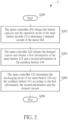
- the discharge control method may be summarized as a process 2, as shown in FIG. 2 .
- the process 2 includes the following steps:
- step S202 when the user rides the electric auxiliary bicycle 1, the main controller 122 is coupled to the motor controller 202 to obtain the present demand current.
- the demand current represents the amount of current that the motor 204 is expected to draw from the main battery 124 and/or the auxiliary battery 144.
- the motor controller 202 may obtain the battery capacity of the multi-battery control system 10 through the first communication interface, and determine the demand current to be drawn according to the operation mode of the user and the battery capacity of the multi-battery control system 10.
- the electric auxiliary bicycle 1 has different demand currents in different operation modes.
- the operation mode may be a more power-consuming sports mode or a relatively power-saving power saving mode, but is not limited thereto.
- the main controller 122 obtains the first information of the main battery 124, and communicates with the auxiliary controller 142 to obtain the second information of the auxiliary battery 144.
- the main battery module 12 and the auxiliary battery module 14 may respectively include a state of charge (SoC) sensor, a battery temperature sensor or a battery voltage sensor for sensing a first SoC value, a first battery temperature and a first battery voltage (the first information) of the main battery 124 and a second SoC value, a second battery temperature and a second battery voltage (the second information) of the auxiliary battery 144.
- SoC state of charge
- the main controller 122 determines the discharging mode of the main battery 124 and the auxiliary battery 144 to manage the power of the main battery 124 and the auxiliary battery 144 according to the first information, the second information and the demand current.
- the main controller 122 may determine whether the first SoC value of the main battery 124 is greater than a first specific value and whether the second SoC value of the auxiliary battery 144 is greater than a second specific value, and determine the discharging mode of the main battery 124 and the auxiliary battery 144 accordingly.
- the main controller 122 controls the main battery 124 to provide current (0A-20A) to the motor module 20, and commands the auxiliary controller 142 to control the auxiliary battery 144 to enter a standby mode and not to output current to the motor module 20.
- the first specific value such as 80%
- the main controller 122 controls the main battery 124 to provide current (0A-20A) to the motor module 20, and commands the auxiliary controller 142 to control the auxiliary battery 144 to provide current (5A) to the motor module 20. It should be noted that, when the second SoC value of the auxiliary battery 144 is less than or equal to the second specific value(3%), the main controller 122 commands the auxiliary controller 142 to control the auxiliary battery 144 to enter into the standby mode.
- the present invention may also add the battery temperatures of the main battery 124 and the auxiliary battery 144 as a determining condition.
- the main controller 122 controls the main battery 124 to provide current (0A-20A) to the motor module 20, and commands the auxiliary controller 142 to control the auxiliary battery 144 to provide current (5A) to the motor module 20.
- the demand current of the motor 204 when the electric auxiliary bicycle 1 is stationary or traveling downhill, the demand current of the motor 204 is in a light load state. In other words, the motor 204 does not need to output electric assistance or only needs to output slight electric assistance.
- the main controller 122 controls the main battery 124 not to output current, and commands the auxiliary controller 142 to control the auxiliary battery 144 to provide current (5A) to the motor module 20 (2A) and the main battery 124 (3A).
- current provided from the auxiliary battery 144 may be a fixed value (5A), and the threshold may be set as the fixed value (5A). Therefore, when the demand current of the motor module 20 is less than current (5A) provided from the auxiliary battery 144, the motor module 20 only draws current (2A) from the auxiliary battery 144.
- the main controller 122 controls the main battery 124 to enter into the charging mode. In this way, in addition to providing 2A current to the motor module 20, the auxiliary battery 144 also provides 3A current to charge the main battery 124.
- the charging control method may be summarized as a process 6, as shown in FIG. 6 .
- the process 6 includes the following steps:
- step S602 the main controller 122 obtains the first information of the main battery 124, and communicates with the auxiliary controller 142 to obtain the second information of the auxiliary battery 144.
- the first information may include the first SoC value of the main battery 124, the first battery temperature and the first battery voltage.
- the second information may include the second SoC value of the auxiliary battery 144, the second battery temperature and the second battery voltage. It should be noted that, those skilled in the art may appropriately add other type of sensors and the sensing information according to the requirements, but is not limited thereto.
- step S604 the main controller 122 determines the charging mode of the main battery 124 and the auxiliary battery 144 according to the first information and the second information to manage the power of the main battery 124 and the auxiliary battery 144.
- the main controller 122 may determine whether the power of the main battery 124 is sufficient, and determine the charging mode of the main battery 124 and the auxiliary battery 144 accordingly. For example, the main controller 122 determines whether the first battery voltage of the main battery 124 is greater than a first voltage or whether the first SoC value is greater than the first specific value, to determine whether the power of the main battery 124 is sufficient, but is not limited thereto.
- the charging module 30 may provide 4A current to charge the multi-battery control system 10, and when the first voltage of the main battery 124 is greater than the first voltage (37V), the main controller 122 controls the main battery 124 and the auxiliary battery 144 to be charged simultaneously. As shown in FIG.
- the main controller 122 controls the main battery 124 to receive the current (2A) provided from the charging module 30, and commands the auxiliary controller 142 to control the auxiliary battery 144 to receive the current (2A) provided from the charging module 30.
- the main battery 124 and the auxiliary battery 144 may be charged simultaneously.
- the charging current distribution of the main battery 124 and the auxiliary battery 144 is (2A+2A), but is not limited thereto.
- the present invention may add the battery temperature of the auxiliary battery 144 as the determining condition.
- the main controller 122 controls the main battery 124 and the auxiliary battery 144 to be charged simultaneously.
- the main controller 122 controls the main battery 124 to be charged, and commands the auxiliary battery 144 not to be charged or to enter into the standby mode. In an embodiment, as shown in FIG.
- the main controller 122 controls the main battery 124 to be charged, and commands the auxiliary controller 142 to control the auxiliary battery 144 not to be charged or to enter into the standby mode.
- the main controller 122 controls the main battery 124 to be charged, and commands the auxiliary controller 142 to control the auxiliary battery 144 not to be charged or to enter into the standby mode.
- all the charging current (4A) of the charging module 30 is provided to the main battery 124 for charging.
- the auxiliary controller 142 of the auxiliary battery module 14 of the present invention receives commands from the main controller 122 to determine whether to charge or discharge the auxiliary battery 144.
- the SoC value of the equivalent battery 1(the second SoC value)/4 + 3(the first SoC value)/4
- the main controller controls the main battery and commands the auxiliary controller to control the auxiliary battery to switch between various discharging modes and charging modes. Therefore, the present invention has the advantage of managing the SoC values of the main battery and the auxiliary battery, thereby improving the utilization efficiency of the main battery and the auxiliary battery and extending the battery life.
Landscapes
- Engineering & Computer Science (AREA)
- Power Engineering (AREA)
- Life Sciences & Earth Sciences (AREA)
- Sustainable Development (AREA)
- Sustainable Energy (AREA)
- Transportation (AREA)
- Mechanical Engineering (AREA)
- Electric Propulsion And Braking For Vehicles (AREA)
- Charge And Discharge Circuits For Batteries Or The Like (AREA)
Abstract
A multi-battery control system (10) is provided. The multi-battery control system includes a main battery module (12), comprising a main controller (122) and a main battery (124), wherein the main controller (124) controls the main battery (124) to provide current to a motor module (20) of an electric vehicle (1), the main controller (124) obtains a first SoC value and a first battery temperature of the main battery; and an auxiliary battery module (14), comprising an auxiliary controller (142) and an auxiliary battery (144), wherein the main controller (124) utilizes a communication interface to communicate with the auxiliary controller (142) to control the auxiliary battery module (14), the auxiliary battery module (14) selectively provides current to the motor module (20) or charges the main battery (124), the main controller (124) obtains a second SoC value and a second battery temperature of the auxiliary battery (144) through the communication interface.
Description
- The present invention relates to a multi-battery control system and an electric vehicle, and more particularly, to a multi-battery control system and an electric vehicle in which a main battery manages an auxiliary battery.
- With the popularity of electric vehicles, the application of light electric vehicles, such as electrically assisted bicycles, electric motorcycles, electric wheelchairs or golf carts, has also been emphasized. At present, the development and the endurance of light electric vehicles are limited by the battery capacity, so more batteries need to be connected in parallel to increase the capacity. For example, a light electric vehicle may be equipped with a main battery and one or more auxiliary batteries to increase the endurance. In addition, in order to simplify the wiring of a light electric vehicle, the auxiliary battery may only be connected to the main battery, which is then responsible for communicating with the motor controller and managing the other auxiliary batteries.
- Therefore, how to manage the power of the main battery and the auxiliary battery has become one of the goals of the industry.
- Therefore, the purpose of the present invention is to provide a multi-battery control system and an electric vehicle to solve the above problem.
- This is achieved by a multi-battery control system and an electric vehicle according to
independent claims - As will be seen more clearly from the detailed description following below, a claimed multi-battery control system is disclosed herein. The multi-battery control system, which is used for an electric vehicle, includes a main battery module, comprising a main controller and a main battery, wherein the main controller controls the main battery to provide current to a motor module of the electric vehicle, and the main controller obtains a first state of charge (SoC) value and a first battery temperature of the main battery; and an auxiliary battery module, comprising an auxiliary controller and an auxiliary battery, wherein the main controller utilizes a communication interface to communicate with the auxiliary controller to control the auxiliary battery module, the auxiliary battery module selectively provides current to the motor module or charges the main battery, and the main controller obtains a second SoC value and a second battery temperature of the auxiliary battery through the communication interface.
- In another aspect of the invention, an claimed electric vehicle is disclosed in the detailed description here below. The electric vehicle includes a motor module, comprising a motor and a motor controller, wherein the motor controller controls the motor to drive the electric vehicle to move; a main battery module, comprising a main controller and a main battery, wherein the main controller utilizes a first communication interface to communicate with the motor controller, and controls the main battery to provide current to the motor, and the main controller obtains a first state of charge (SoC) value and a first battery temperature of the main battery; and an auxiliary battery module, comprising an auxiliary controller and an auxiliary battery, wherein the main controller utilizes a second communication interface to communicate with the auxiliary controller to control the auxiliary battery module, the auxiliary battery module selectively provides current to the motor module or charges the main battery, and the main controller obtains a second SoC value and a second battery temperature of the auxiliary battery through the communication interface.
-
-
FIG. 1A andFIG. 1B are schematic diagrams of a multi-battery control system and an electric auxiliary bicycle according to an embodiment of the present invention. -
FIG. 2 is a flow chart of a discharge control method according to an embodiment of the present invention. -
FIG. 3 is a flow chart of a discharging mode of the multi-battery control system according to an embodiment of the present invention. -
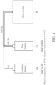
FIG. 4 is a flow chart of a discharging mode of the multi-battery control system according to another embodiment of the present invention. -
FIG. 5 is a flow chart of a discharging mode of the multi-battery control system according to another embodiment of the present invention. -
FIG. 6 is a flow chart of a charging control method according to an embodiment of the present invention. -
FIG. 7 is a flow chart of a charging mode of the multi-battery control system according to an embodiment of the present invention. -
FIG. 8 is a flow chart of a charging mode of the multi-battery control system according to another embodiment of the present invention. - Certain terms are used throughout the description and following claims to refer to particular components. As one skilled in the art will appreciate, hardware manufacturers may refer to a component by different names. This document does not intend to distinguish between components that differ in name but not function. In the following description and in the claims, the terms "include" and "comprise" are utilized in an open-ended fashion, and thus should be interpreted to mean "include, but not limited to". Also, the term "couple" is intended to mean either an indirect or direct electrical connection. Accordingly, if one device is coupled to another device, that connection may be through a direct electrical connection, or through an indirect electrical connection via other devices and connections.
-
FIG. 1A andFIG. 1B are schematic diagrams of amulti-battery control system 10 and an electricauxiliary bicycle 1 according to an embodiment of the present invention. Themulti-battery control system 10 includes amain battery module 12 and anauxiliary battery module 14, and may be installed at any position of the electricauxiliary bicycle 1 to provide current to amotor module 20 of the electricauxiliary bicycle 1. For example, themain battery module 12 may be installed in the down tube of the electricauxiliary bicycle 1; theauxiliary battery module 14 may be installed on the water bottle cage of the electricauxiliary bicycle 1; themotor module 20 may be installed in the front wheel hub, rear wheel hub or front motor, rear motor or mid-mounted motor of the central axis of the electricauxiliary bicycle 1, but is not limited thereto. It should be noted that in addition to the electricauxiliary bicycle 1, themulti-battery control system 10 of the present invention may also be applied for electric motorcycles, electric wheelchairs, golf carts or other form of electric vehicles. Those skilled in the art may make appropriate adjustments according to system requirements. - In detail, as shown in
FIG. 1A , themain battery module 12 includes amain controller 122 and amain battery 124. Theauxiliary battery module 14 includes an auxiliary controller 142 and anauxiliary battery 144. Themotor module 20 includes amotor controller 202 and amotor 204. Themain controller 122 is coupled to themotor controller 202, and controls themain battery 124 to provide current to themotor 204. It should be noted that, themotor 204 and themotor controller 202 of themotor module 20 may be integrated into one component or separated into two components. In addition, themain controller 122 is coupled to the auxiliary controller 142 to control theauxiliary battery module 14, so that theauxiliary battery 144 selectively provides current to themotor module 20 or charges themain battery 124. It should be noted that themain controller 122 utilizes a first communication interface to communicate with themotor controller 202, and utilizes a second communication interface to communicate with the auxiliary controller 142. For example, the first communication interface may be a universal asynchronous receiver/transmitter (UART), the second communication interface may be a controller area network (CAN), but is not limited thereto. It should be noted that the vehicle communication protocols such as the universal asynchronous transceiver and controller area network are well known in the art, so it is not repeated here. In addition, as shown inFIG. 1A , themulti-battery control system 10 may be coupled to acharging module 30 and enter into a charging state to charge themain battery 124 and/or theauxiliary battery 144. - It should be noted that, the
main battery module 12 or themain controller 122 may include a microcontroller unit (MCU) and a memory. The memory stores a programing code for instructing the MCU to execute a discharge control method. The discharge control method may be summarized as aprocess 2, as shown inFIG. 2 . Theprocess 2 includes the following steps: - Step S200: Start.
- Step S202: The
motor controller 202 obtains the battery capacity and the operation mode of themain battery module 12 to determine a demand current of themotor 204. - Step S204: The
main controller 122 obtains the demand current and obtains a first information of themain battery 124 and a second information of theauxiliary battery 144. - Step S206: The
main controller 122 determines the discharging mode of themain battery 124 and theauxiliary battery 144 according to the first information, the second information and the demand current. - Step S208: End.
- According to the
process 2, in step S202, when the user rides the electricauxiliary bicycle 1, themain controller 122 is coupled to themotor controller 202 to obtain the present demand current. The demand current represents the amount of current that themotor 204 is expected to draw from themain battery 124 and/or theauxiliary battery 144. It should be noted that themotor controller 202 may obtain the battery capacity of themulti-battery control system 10 through the first communication interface, and determine the demand current to be drawn according to the operation mode of the user and the battery capacity of themulti-battery control system 10. In other words, the electricauxiliary bicycle 1 has different demand currents in different operation modes. The operation mode may be a more power-consuming sports mode or a relatively power-saving power saving mode, but is not limited thereto. In step S204, themain controller 122 obtains the first information of themain battery 124, and communicates with the auxiliary controller 142 to obtain the second information of theauxiliary battery 144. In detail, themain battery module 12 and theauxiliary battery module 14 may respectively include a state of charge (SoC) sensor, a battery temperature sensor or a battery voltage sensor for sensing a first SoC value, a first battery temperature and a first battery voltage (the first information) of themain battery 124 and a second SoC value, a second battery temperature and a second battery voltage (the second information) of theauxiliary battery 144. It should be noted that those skilled in the art may appropriately add other type of sensors and the sensing information according to the requirements, but is not limited thereto. In step S206, themain controller 122 determines the discharging mode of themain battery 124 and theauxiliary battery 144 to manage the power of themain battery 124 and theauxiliary battery 144 according to the first information, the second information and the demand current. - In detail, the
main controller 122 may determine whether the first SoC value of themain battery 124 is greater than a first specific value and whether the second SoC value of theauxiliary battery 144 is greater than a second specific value, and determine the discharging mode of themain battery 124 and theauxiliary battery 144 accordingly. In an embodiment, as shown inFIG. 3 , when the first SoC value of themain battery 124 is greater than the first specific value (such as 80%), themain controller 122 controls themain battery 124 to provide current (0A-20A) to themotor module 20, and commands the auxiliary controller 142 to control theauxiliary battery 144 to enter a standby mode and not to output current to themotor module 20. In another embodiment, as shown inFIG. 4 , when the first SoC value of themain battery 124 is less than or equal to the first specific value (80%) and the second SoC value of theauxiliary battery 144 is greater than the second specific value (3%), themain controller 122 controls themain battery 124 to provide current (0A-20A) to themotor module 20, and commands the auxiliary controller 142 to control theauxiliary battery 144 to provide current (5A) to themotor module 20. It should be noted that, when the second SoC value of theauxiliary battery 144 is less than or equal to the second specific value(3%), themain controller 122 commands the auxiliary controller 142 to control theauxiliary battery 144 to enter into the standby mode. In other words, when the battery capacity of theauxiliary battery 144 is extremely low, theauxiliary battery 144 does not provide current to themotor module 20, and the remaining battery capacity is only used to maintain the communication between themain controller 122 and the auxiliary controller 142. In another embodiment, as shown inFIG. 4 , in addition to determining the discharging mode of themain battery 124 and theauxiliary battery 144 according to the SoC values of themain battery 124 and theauxiliary battery 144, the present invention may also add the battery temperatures of themain battery 124 and theauxiliary battery 144 as a determining condition. For example, when the first SoC value of themain battery 124 is less than or equal to the first specific value (80%), the second SoC value of theauxiliary battery 144 is greater than the second specific value (3%), a first battery temperature of themain battery 124 is less than or equal to a first temperature (44°C) and a second battery temperature of theauxiliary battery 144 is less than or equal to a second temperature (69°C), themain controller 122 controls themain battery 124 to provide current (0A-20A) to themotor module 20, and commands the auxiliary controller 142 to control theauxiliary battery 144 to provide current (5A) to themotor module 20. It should be noted that, in all embodiments of the present invention, those skilled in the art may appropriately add other type of sensors and the sensing information as the determining conditions according to the requirements, for example, the temperatures of the transistors in theauxiliary battery module 14, but is not limited thereto. - In an embodiment, when the electric
auxiliary bicycle 1 is stationary or traveling downhill, the demand current of themotor 204 is in a light load state. In other words, themotor 204 does not need to output electric assistance or only needs to output slight electric assistance. As shown inFIG. 5 , when the demand current of themotor module 20 or themotor 204 is less than or equal to a threshold and the first SoC value of themain battery 124 is less than or equal to the first specific value (5A), themain controller 122 controls themain battery 124 not to output current, and commands the auxiliary controller 142 to control theauxiliary battery 144 to provide current (5A) to the motor module 20 (2A) and the main battery 124 (3A). It should be noted that, in the above embodiments, current provided from theauxiliary battery 144 may be a fixed value (5A), and the threshold may be set as the fixed value (5A). Therefore, when the demand current of themotor module 20 is less than current (5A) provided from theauxiliary battery 144, themotor module 20 only draws current (2A) from theauxiliary battery 144. In addition, themain controller 122 controls themain battery 124 to enter into the charging mode. In this way, in addition to providing 2A current to themotor module 20, theauxiliary battery 144 also provides 3A current to charge themain battery 124. - On the other hand, when the
multi-battery control system 10 is coupled to the chargingmodule 30 and enters into the charging mode, the programing code also instructs the MCU to execute a charging control method. The charging control method may be summarized as aprocess 6, as shown inFIG. 6 . Theprocess 6 includes the following steps: - Step S600: Start.
- Step S602: Obtain a first information of the
main battery 124 and a second information of theauxiliary battery 144. - Step S604: Determine the charging mode of the
main battery 124 and theauxiliary battery 144 according to the first information and the second information. - Step S606: End.
- According to the
process 6, in step S602, themain controller 122 obtains the first information of themain battery 124, and communicates with the auxiliary controller 142 to obtain the second information of theauxiliary battery 144. As mentioned above, the first information may include the first SoC value of themain battery 124, the first battery temperature and the first battery voltage. The second information may include the second SoC value of theauxiliary battery 144, the second battery temperature and the second battery voltage. It should be noted that, those skilled in the art may appropriately add other type of sensors and the sensing information according to the requirements, but is not limited thereto. In step S604, themain controller 122 determines the charging mode of themain battery 124 and theauxiliary battery 144 according to the first information and the second information to manage the power of themain battery 124 and theauxiliary battery 144. - In detail, the
main controller 122 may determine whether the power of themain battery 124 is sufficient, and determine the charging mode of themain battery 124 and theauxiliary battery 144 accordingly. For example, themain controller 122 determines whether the first battery voltage of themain battery 124 is greater than a first voltage or whether the first SoC value is greater than the first specific value, to determine whether the power of themain battery 124 is sufficient, but is not limited thereto. In an embodiment, the chargingmodule 30 may provide 4A current to charge themulti-battery control system 10, and when the first voltage of themain battery 124 is greater than the first voltage (37V), themain controller 122 controls themain battery 124 and theauxiliary battery 144 to be charged simultaneously. As shown inFIG. 7 , themain controller 122 controls themain battery 124 to receive the current (2A) provided from the chargingmodule 30, and commands the auxiliary controller 142 to control theauxiliary battery 144 to receive the current (2A) provided from the chargingmodule 30. In other words, when the power of themain battery 124 is sufficient, themain battery 124 and theauxiliary battery 144 may be charged simultaneously. It should be noted that the charging current distribution of themain battery 124 and theauxiliary battery 144 is (2A+2A), but is not limited thereto. In another embodiment, as shown inFIG. 7 , in addition to determining the charging mode of themain battery 124 and theauxiliary battery 144 according to the first voltage of themain battery 124, the present invention may add the battery temperature of theauxiliary battery 144 as the determining condition. For example, when the first voltage of themain battery 124 is greater than the first voltage (37V) and the second battery temperature of theauxiliary battery 144 is less than or equal to a third temperature (54°C), themain controller 122 controls themain battery 124 and theauxiliary battery 144 to be charged simultaneously. When the first voltage of themain battery 124 is greater than the first voltage (37V) and the second battery temperature of theauxiliary battery 144 is greater than the third temperature (54°C), themain controller 122 controls themain battery 124 to be charged, and commands theauxiliary battery 144 not to be charged or to enter into the standby mode. In an embodiment, as shown inFIG. 8 , when the first voltage of themain battery 124 is less than or equal to the first voltage (37V), themain controller 122 controls themain battery 124 to be charged, and commands the auxiliary controller 142 to control theauxiliary battery 144 not to be charged or to enter into the standby mode. In other words, when the power of themain battery 124 is not sufficient, all the charging current (4A) of the chargingmodule 30 is provided to themain battery 124 for charging. - In short, the auxiliary controller 142 of the
auxiliary battery module 14 of the present invention receives commands from themain controller 122 to determine whether to charge or discharge theauxiliary battery 144. It should be noted that, the auxiliary controller 142 is only coupled to themain controller 122 through the controller area network CAN, but is not directly coupled to themotor controller 202. Therefore, from the perspective of themotor controller 202, themain battery 124 and theauxiliary battery 144 of themulti-battery control system 10 may be regarded as an equivalent battery. For example, if the capacity of themain battery 124 is three times of the capacity of theauxiliary battery 144, then the capacity and the SoC value of the equivalent battery satisfy the following equation:
- The SoC value of the equivalent battery = 1(the second SoC value)/4 + 3(the first SoC value)/4
- In summary, in the multi-battery control system of the present invention, the main controller controls the main battery and commands the auxiliary controller to control the auxiliary battery to switch between various discharging modes and charging modes. Therefore, the present invention has the advantage of managing the SoC values of the main battery and the auxiliary battery, thereby improving the utilization efficiency of the main battery and the auxiliary battery and extending the battery life.
Claims (10)
- A multi-battery control system (10), for an electric vehicle (1), characterized by comprising:a main battery module (12), comprising a main controller (122) and a main battery (124), wherein the main controller (122) controls the main battery (124) to provide current to a motor module (20) of the electric vehicle (1), and the main controller (122) obtains a first state of charge (SoC) value and a first battery temperature of the main battery (124); andan auxiliary battery module (14), comprising an auxiliary controller (142) and an auxiliary battery (144), wherein the main controller (122) utilizes a communication interface to communicate with the auxiliary controller (142) to control the auxiliary battery module (14), the auxiliary battery module (14) selectively provides current to the motor module (20) or charges the main battery (124), and the main controller (122) obtains a second SoC value and a second battery temperature of the auxiliary battery (144) through the communication interface.
- An electric vehicle (1), characterized by comprising:a motor module (20), comprising a motor (204) and a motor controller (202), wherein the motor controller (202) controls the motor (204) to drive the electric vehicle (1) to move;a main battery module (12), comprising a main controller (122) and a main battery (124), wherein the main controller (122) utilizes a first communication interface to communicate with the motor controller (202), and controls the main battery (124) to provide current to the motor (204), and the main controller (122) obtains a first state of charge (SoC) value and a first battery temperature of the main battery (124); andan auxiliary battery module (14), comprising an auxiliary controller (142) and an auxiliary battery, wherein the main controller (122) utilizes a second communication interface to communicate with the auxiliary controller (142) to control the auxiliary battery module (14), the auxiliary battery module (14) selectively provides current to the motor module (20) or charges the main battery (124), and the main controller (122) obtains a second SoC value and a second battery temperature of the auxiliary battery (144) through the communication interface.
- The multi-battery control system (10) of claim 1 or the electric vehicle (1) of claim 2, characterized in that when the first SoC value of the main battery (124) is greater than a first specific value, the main battery (124) provides current to the motor module (20), and the main controller (122) controls the auxiliary battery (144) not to output current to the motor module (20).
- The multi-battery control system (10) of claim 1 or the electric vehicle (1) of claim 2, characterized in that when the first SoC value of the main battery (124) is less than or equal to the first specific value and the second SoC value of the auxiliary battery (144) is greater than a second specific value, the main battery (124) and the auxiliary battery (144) simultaneously provide current to the motor module (20).
- The multi-battery control system (10) or the electric vehicle (1) of claim 4, characterized in that when the first battery temperature is less than or equal to a first temperature and the second battery temperature is less than or equal to a second temperature, the main battery (124) and the auxiliary battery (144) simultaneously provide current to the motor module (20).
- The multi-battery control system (10) of claim 1 or the electric vehicle (1) of claim 2, characterized in that when a demand current of the motor module (20) is less than or equal to a threshold and the first SoC value is less than or equal to the first specific value, the auxiliary battery (144) provides current to the motor module (20) and the main battery (124).
- The multi-battery control system (10) or the electric vehicle (1) of claim 6, characterized in that output current of the auxiliary battery (144) is a fixed value.
- The multi-battery control system (10) of claim 1 or the electric vehicle (1) of claim 2, characterized in that when the multi-battery control system is in a charging state and a voltage of the main battery (124) is greater than a first voltage, the main controller (122) controls the main battery (124) and the auxiliary battery (144) to be charged simultaneously.
- The multi-battery control system (10) or the electric vehicle (1) of claim 8, characterized in that when the second battery temperature of the auxiliary battery (144) is less than or equal to a third temperature, the main controller (122) controls the main battery (124) and the auxiliary battery (144) to be charged simultaneously.
- The multi-battery control system (10) of claim 1 or the electric vehicle (1) of claim 2, characterized in that when the multi-battery control system is in a charging state and a voltage of the main battery (124) is less than or equal to a first voltage, the main controller (122) controls the main battery (124) to be charged and the auxiliary battery (144) not to be charged.
Applications Claiming Priority (2)
| Application Number | Priority Date | Filing Date | Title |
|---|---|---|---|
| US202363458663P | 2023-04-12 | 2023-04-12 | |
| TW113102774A TWI905643B (en) | 2023-04-12 | 2024-01-24 | Multi-battery control system and electric vehicle |
Publications (1)
| Publication Number | Publication Date |
|---|---|
| EP4446162A1 true EP4446162A1 (en) | 2024-10-16 |
Family
ID=90720841
Family Applications (1)
| Application Number | Title | Priority Date | Filing Date |
|---|---|---|---|
| EP24169762.2A Pending EP4446162A1 (en) | 2023-04-12 | 2024-04-11 | Multi-battery control system and electric vehicle |
Country Status (3)
| Country | Link |
|---|---|
| US (1) | US20240343160A1 (en) |
| EP (1) | EP4446162A1 (en) |
| JP (1) | JP7762760B2 (en) |
Citations (4)
| Publication number | Priority date | Publication date | Assignee | Title |
|---|---|---|---|---|
| US20140111121A1 (en) * | 2012-10-19 | 2014-04-24 | Yi-Tsung Wu | Battery configuration for an electric vehicle |
| US20160250937A1 (en) * | 2015-02-27 | 2016-09-01 | GM Global Technology Operations LLC | Electric bike extended range battery power electronics and control |
| US20170021739A1 (en) * | 2015-04-30 | 2017-01-26 | Yamaha Hatsudoki Kabushiki Kaisha | Straddled electric vehicle, and charging system for straddled electric vehicle |
| US20220080908A1 (en) * | 2020-09-16 | 2022-03-17 | Subaru Corporation | Vehicular power supply device |
Family Cites Families (5)
| Publication number | Priority date | Publication date | Assignee | Title |
|---|---|---|---|---|
| JP2018182866A (en) | 2017-04-10 | 2018-11-15 | 三菱自動車工業株式会社 | Battery system and electric vehicle |
| JP2022517717A (en) | 2018-11-29 | 2022-03-10 | クラブ カー エルエルシー | Auxiliary power output for battery management system |
| JP7413242B2 (en) * | 2020-12-03 | 2024-01-15 | 本田技研工業株式会社 | power system |
| JP7657082B2 (en) | 2021-03-19 | 2025-04-04 | 本田技研工業株式会社 | Vehicle control device, vehicle control method, and program |
| JP2022184602A (en) | 2021-06-01 | 2022-12-13 | 本田技研工業株式会社 | Electric vehicle and sharing system |
-
2024
- 2024-03-13 US US18/604,481 patent/US20240343160A1/en active Pending
- 2024-04-04 JP JP2024060645A patent/JP7762760B2/en active Active
- 2024-04-11 EP EP24169762.2A patent/EP4446162A1/en active Pending
Patent Citations (4)
| Publication number | Priority date | Publication date | Assignee | Title |
|---|---|---|---|---|
| US20140111121A1 (en) * | 2012-10-19 | 2014-04-24 | Yi-Tsung Wu | Battery configuration for an electric vehicle |
| US20160250937A1 (en) * | 2015-02-27 | 2016-09-01 | GM Global Technology Operations LLC | Electric bike extended range battery power electronics and control |
| US20170021739A1 (en) * | 2015-04-30 | 2017-01-26 | Yamaha Hatsudoki Kabushiki Kaisha | Straddled electric vehicle, and charging system for straddled electric vehicle |
| US20220080908A1 (en) * | 2020-09-16 | 2022-03-17 | Subaru Corporation | Vehicular power supply device |
Also Published As
| Publication number | Publication date |
|---|---|
| US20240343160A1 (en) | 2024-10-17 |
| JP2024152655A (en) | 2024-10-25 |
| JP7762760B2 (en) | 2025-10-30 |
Similar Documents
| Publication | Publication Date | Title |
|---|---|---|
| CN111231763B (en) | A dual-source battery pack switching method and system | |
| US8143843B2 (en) | Electrically-driven vehicle and method for controlling charging of electrically-driven vehicle | |
| JP5029331B2 (en) | Vehicle power supply | |
| US8368347B2 (en) | Vehicular charging system | |
| EP2272722B1 (en) | Power source apparatus for vehicle | |
| US11830999B2 (en) | Hybrid energy storage module system having auxiliary battery | |
| JP3180304B2 (en) | Power circuit of hybrid car | |
| EP1253698A2 (en) | Power supply equipment for motor vehicle | |
| CN110857038B (en) | Power supply system of electric vehicle and power supply method thereof | |
| JP2004023803A (en) | Battery controller for assembled battery | |
| CN102658780B (en) | Output control apparatus in electric vehicle | |
| CN114932835B (en) | An electric vehicle emergency cruising range energy storage and replacement system and control method thereof | |
| EP1462300A1 (en) | Energy management system for electric vehicle | |
| WO2012067116A1 (en) | Power supply control device | |
| CN120498089B (en) | Energy recovery control method and device, vehicle and equipment | |
| JP2024526756A (en) | System and method for controlling charging between battery packs | |
| US20240343160A1 (en) | Multi-battery Control System and Electric Vehicle | |
| JP2020127299A (en) | Vehicle power supply system | |
| KR102469456B1 (en) | Auxiliary power management apparatus for vehicle | |
| JP2000217206A (en) | Electric vehicle charging control device | |
| US20250026238A1 (en) | Balancing States of Charge of Battery Modules for an Electric Vehicle | |
| KR102624683B1 (en) | Battery system and control method thereof | |
| CN207496476U (en) | High-voltage detecting circuit, detector, cell apparatus and delivery vehicle | |
| JP7658311B2 (en) | Electric vehicle control device | |
| TWI905643B (en) | Multi-battery control system and electric vehicle |
Legal Events
| Date | Code | Title | Description |
|---|---|---|---|
| PUAI | Public reference made under article 153(3) epc to a published international application that has entered the european phase |
Free format text: ORIGINAL CODE: 0009012 |
|
| STAA | Information on the status of an ep patent application or granted ep patent |
Free format text: STATUS: THE APPLICATION HAS BEEN PUBLISHED |
|
| AK | Designated contracting states |
Kind code of ref document: A1 Designated state(s): AL AT BE BG CH CY CZ DE DK EE ES FI FR GB GR HR HU IE IS IT LI LT LU LV MC ME MK MT NL NO PL PT RO RS SE SI SK SM TR |
|
| STAA | Information on the status of an ep patent application or granted ep patent |
Free format text: STATUS: REQUEST FOR EXAMINATION WAS MADE |
|
| 17P | Request for examination filed |
Effective date: 20250410 |