EP4446131A1 - Tire - Google Patents
Tire Download PDFInfo
- Publication number
- EP4446131A1 EP4446131A1 EP22903750.2A EP22903750A EP4446131A1 EP 4446131 A1 EP4446131 A1 EP 4446131A1 EP 22903750 A EP22903750 A EP 22903750A EP 4446131 A1 EP4446131 A1 EP 4446131A1
- Authority
- EP
- European Patent Office
- Prior art keywords
- tire
- tag
- indicator
- different
- electronic tag
- Prior art date
- Legal status (The legal status is an assumption and is not a legal conclusion. Google has not performed a legal analysis and makes no representation as to the accuracy of the status listed.)
- Pending
Links
Images





Classifications
-
- G—PHYSICS
- G06—COMPUTING OR CALCULATING; COUNTING
- G06K—GRAPHICAL DATA READING; PRESENTATION OF DATA; RECORD CARRIERS; HANDLING RECORD CARRIERS
- G06K19/00—Record carriers for use with machines and with at least a part designed to carry digital markings
- G06K19/06—Record carriers for use with machines and with at least a part designed to carry digital markings characterised by the kind of the digital marking, e.g. shape, nature, code
- G06K19/067—Record carriers with conductive marks, printed circuits or semiconductor circuit elements, e.g. credit or identity cards also with resonating or responding marks without active components
- G06K19/07—Record carriers with conductive marks, printed circuits or semiconductor circuit elements, e.g. credit or identity cards also with resonating or responding marks without active components with integrated circuit chips
- G06K19/077—Constructional details, e.g. mounting of circuits in the carrier
- G06K19/07749—Constructional details, e.g. mounting of circuits in the carrier the record carrier being capable of non-contact communication, e.g. constructional details of the antenna of a non-contact smart card
- G06K19/07758—Constructional details, e.g. mounting of circuits in the carrier the record carrier being capable of non-contact communication, e.g. constructional details of the antenna of a non-contact smart card arrangements for adhering the record carrier to further objects or living beings, functioning as an identification tag
- G06K19/07764—Constructional details, e.g. mounting of circuits in the carrier the record carrier being capable of non-contact communication, e.g. constructional details of the antenna of a non-contact smart card arrangements for adhering the record carrier to further objects or living beings, functioning as an identification tag the adhering arrangement making the record carrier attachable to a tyre
-
- B—PERFORMING OPERATIONS; TRANSPORTING
- B60—VEHICLES IN GENERAL
- B60C—VEHICLE TYRES; TYRE INFLATION; TYRE CHANGING; CONNECTING VALVES TO INFLATABLE ELASTIC BODIES IN GENERAL; DEVICES OR ARRANGEMENTS RELATED TO TYRES
- B60C19/00—Tyre parts or constructions not otherwise provided for
-
- B—PERFORMING OPERATIONS; TRANSPORTING
- B60—VEHICLES IN GENERAL
- B60C—VEHICLE TYRES; TYRE INFLATION; TYRE CHANGING; CONNECTING VALVES TO INFLATABLE ELASTIC BODIES IN GENERAL; DEVICES OR ARRANGEMENTS RELATED TO TYRES
- B60C11/00—Tyre tread bands; Tread patterns; Anti-skid inserts
-
- B—PERFORMING OPERATIONS; TRANSPORTING
- B60—VEHICLES IN GENERAL
- B60C—VEHICLE TYRES; TYRE INFLATION; TYRE CHANGING; CONNECTING VALVES TO INFLATABLE ELASTIC BODIES IN GENERAL; DEVICES OR ARRANGEMENTS RELATED TO TYRES
- B60C13/00—Tyre sidewalls; Protecting, decorating, marking, or the like, thereof
- B60C13/001—Decorating, marking or the like
-
- B—PERFORMING OPERATIONS; TRANSPORTING
- B60—VEHICLES IN GENERAL
- B60C—VEHICLE TYRES; TYRE INFLATION; TYRE CHANGING; CONNECTING VALVES TO INFLATABLE ELASTIC BODIES IN GENERAL; DEVICES OR ARRANGEMENTS RELATED TO TYRES
- B60C15/00—Tyre beads, e.g. ply turn-up or overlap
-
- B—PERFORMING OPERATIONS; TRANSPORTING
- B60—VEHICLES IN GENERAL
- B60C—VEHICLE TYRES; TYRE INFLATION; TYRE CHANGING; CONNECTING VALVES TO INFLATABLE ELASTIC BODIES IN GENERAL; DEVICES OR ARRANGEMENTS RELATED TO TYRES
- B60C23/00—Devices for measuring, signalling, controlling, or distributing tyre pressure or temperature, specially adapted for mounting on vehicles; Arrangement of tyre inflating devices on vehicles, e.g. of pumps or of tanks; Tyre cooling arrangements
- B60C23/02—Signalling devices actuated by tyre pressure
- B60C23/04—Signalling devices actuated by tyre pressure mounted on the wheel or tyre
- B60C23/0491—Constructional details of means for attaching the control device
- B60C23/0493—Constructional details of means for attaching the control device for attachment on the tyre
-
- B—PERFORMING OPERATIONS; TRANSPORTING
- B60—VEHICLES IN GENERAL
- B60C—VEHICLE TYRES; TYRE INFLATION; TYRE CHANGING; CONNECTING VALVES TO INFLATABLE ELASTIC BODIES IN GENERAL; DEVICES OR ARRANGEMENTS RELATED TO TYRES
- B60C19/00—Tyre parts or constructions not otherwise provided for
- B60C2019/004—Tyre sensors other than for detecting tyre pressure
Definitions
- the present disclosure relates to a tire.
- Patent Literature (PTL) 1 describes a pneumatic tire equipped with a transponder.
- the transponder is capable of providing various information regarding the tire and data on the tire in use.
- the transponder has a transmitting and receiving function and a storage function, and is disposed, for example, on a sidewall portion.
- An identification label indicating the position of the transponder is provided on a tire outer surface of the sidewall portion on which the transponder is disposed or a tire outer surface of a sidewall portion on the opposite side of the sidewall portion on which the transponder is disposed.
- the identification label indicating the position of the transponder is distinguished from other portions based on color or shape.
- any of saturation, brightness, and hue may differ.
- the identification label is in a three-dimensional shape, a concave shape depressed from the tire outer surface, a convex shape protruding from the tire outer surface, a combination of concave and convex shapes, or the like is employed.
- PTL 2 describes a method for processing rubber materials including rubber from rubber-containing products such as tires.
- PTL 2 states that the rubber-containing products, such as tires, are processed by separating rubber from other materials.
- an electronic chip that functions as a transponder may be installed within a tire or on an inner surface of a tire.
- the electronic chip may then be able to provide information regarding the tire to an external terminal through communication with the electronic chip. This makes it easy to obtain a tire model, information on distribution and sales, a usage history, driving information on a vehicle on which the tire is mounted, and the like, to acquire, from the tire, information necessary for recycling the tire (e.g., information regarding constituent materials of the tire), and to manage traceability of the tire for proper disposal and recycling.
- Indicating the position of the electronic tag on an outer surface of the tire is convenient for acquiring information by a terminal device, which acquires information from the electronic tag, because where to hold a sensor can be recognized by the indication. It is also convenient when the electronic tag is separated from the tire in a separation process for disposal or recycling of the tire because the position of the electronic tag can be known.
- the electronic tag when the electronic tag is embedded within the tire, it may be necessary to hollow out the tire to remove and separate the electronic tag. Therefore, it is desirable to be able to recognize an area in which the electronic tag is installed, as the position of the electronic tag.
- the present disclosure is made in view of such circumstances. It would be helpful to provide a tire that can indicate an area in which an electronic tag is embedded.
- a tire according to the present disclosure to achieve the above object includes:
- FIGS. 1 and 2 illustrate a tire 100 of this embodiment.
- FIG. 1 illustrates a cross-section of the tire 100 intersecting a circumferential direction C (see FIG. 2).
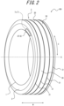
- FIG. 2 is a perspective view of the tire 100.
- the tire 100 includes an electronic tag 7 (hereinafter referred to as tag 7) disposed inside from a surface of the tire 100, and an indicator 8 indicating the position of the tag 7.
- tag 7 is a so-called RFID tag, which is an electronic circuit device or electronic chip that includes an antenna circuit for establishing communication, a storage circuit, and a control circuit.
- RFID tag is an electronic circuit device or electronic chip that includes an antenna circuit for establishing communication, a storage circuit, and a control circuit.
- the tire 100 includes bead portions 1, which are disposed on the sides of the tire 100 and secure the tire 100 to a rim, sidewall portions 2, which constitute the sides of the tire 100, and a tread portion 3, which contacts a road surface.
- the tire 100 is formed in the shape of an approximately circular annulus centered on an axial center G. That is, the tread portion 3, the sidewall portions 2, and the bead portions 1 are in the shapes of approximately circular annuluses that are centered in common on the axial center G.
- a width direction W, the circumferential direction C (see FIG. 2 ), and a radial direction R of the tire 100 illustrated in FIGS. 1 and 2 have the same meaning as a width direction, a circumferential direction, and a radial direction of the tread portion 3.
- a radial direction R an outside of the annulus is referred to as a radial outside, and an inside of the annulus is referred to as a radial inside.
- the tire 100 includes, as its internal structure, a carcass 5, which is a cord layer forming a skeleton of the tire 100, bead cores 4, which are internal skeletons of the bead portions 1 and support the carcass 5, and belts 6, which are reinforcement belts stretched along the circumferential direction C between a surface of the tread portion 3 and the carcass 5.
- a carcass 5 which is a cord layer forming a skeleton of the tire 100
- bead cores 4 which are internal skeletons of the bead portions 1 and support the carcass 5,
- belts 6, which are reinforcement belts stretched along the circumferential direction C between a surface of the tread portion 3 and the carcass 5.
- the bead portions 1, the sidewall portions 2, and the tread portion 3 each contain synthetic rubber.
- the synthetic rubber of the bead portions 1 and the sidewall portions 2 is referred to as side rubber.
- the synthetic rubber of the tread portion 3 is referred to as tread rubber.
- the bead cores 4, the carcass 5, and the belts 6 are embedded in the side rubber and the tread rubber.
- radial outside ends of the sidewall portions 2 are integrally connected to both ends of the tread portion 3 in the width direction W.
- the bead portions 1 are integrally connected to radial inside ends of the sidewall portions 2.
- the cross-section of the tire 100 intersecting the circumferential direction C is in the shape of the letter C of the alphabet.
- the surface of the tire 100 in this embodiment refers to an outside surface (hereinafter also referred to as outer surface) and an inside surface (hereinafter also referred to as inner surface) of the C-shaped arc in the C-shape of the tire 100.
- the tread portion 3 is formed with a tread pattern, which has a plurality of convex portions 30 (an example of a tread surface) whose outer circumferential surfaces contact the road surface and a plurality of concave portions 31 that is concave radially inside relative to the convex portions 30.
- the concave portions 31 are, for example, circumferential grooves. Note that, the outer circumferential surfaces constitute a radial outside surface of the tread portion 3 in the tire 100.
- the tire 100 in this embodiment further includes the tag 7 and the indicator 8, as described above.
- the cross-section of the tire 100 illustrated in FIG. 1 is a cross-section of the tire 100 viewed along the circumferential direction C (see FIG. 2 ), and is a cross-section of a part including the tag 7 and the indicator 8.
- FIGS. 1 and 2 illustrate a case in which the tag 7 is disposed within the tire 100 (inside from the surface), on a side closer to the bead portion 1 in one of the sidewall portions 2, and is disposed outside from the carcass 5 (see FIG. 2 ) in the width direction W of the tire 100.
- the tag 7 is embedded (disposed) in the side of the tire 100.
- the outside in the width direction W refers to the same side as the sidewall portion 2 side, viewed from the tread portion 3.
- FIG. 3 illustrates an enlarged cross-sectional view of a part of the sidewall portion 2, in the cross-sectional view illustrated in FIG. 1 .
- the indicator 8 is formed in the sidewall portion 2.
- the indicator 8 is disposed in such a position that the normal from the position of the tag 7 to an outer surface of the sidewall portion 2, which is the outer surface of the tire 100 closest to the tag 7, intersects the said outer surface. This allows the indicator 8 to clearly indicate an area in which the tag 7 is embedded. This facilitates removal of the tag 7 when the tire 100 is disposed of or recycled. In a case in which a worker performs communication with the tag 7 using a terminal device, the indicator 8 can indicate the position of the tag 7 to the worker, so that the worker can easily recognize the position of the tag 7 and smoothly perform communication with the tag 7.
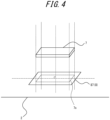
- FIG. 4 is a schematic diagram illustrating the positional relationship between the tag 7 and the indicator 8, for the purpose of illustrating the position of installation of the indicator 8.
- FIG. 5 is an enlarged diagram of FIG. 2 , which illustrates, with enlargement, the vicinity of the indicator 8 disposed in the sidewall portion 2.
- an orthogonal projection image (an example of a projection image) of the outer shape of the tag 7 projected onto the outer surface of the sidewall portion 2 is illustrated as a tag projection image 7s.
- FIG. 4 an orthogonal projection image (an example of a projection image) of the outer shape of the tag 7 projected onto the outer surface of the sidewall portion 2 is illustrated as a tag projection image 7s.
- the indicator 8 is formed in an area that includes the outer surface of the sidewall portion 2 and encompasses the tag projection image 7s.
- the orthogonal projection image of the outer shape of the tag 7 projected onto the surface of the sidewall portion 2, i.e. the tag projection image 7s is an image of projecting the outer shape of the tag 7 onto the surface of the tire 100 closest to the center of the tag 7 (in this embodiment, the outer surface of the sidewall portion 2), in a direction along the normal from the center of the tag 7 to the said outer surface.
- the indicator 8 may be formed in the area that encompasses the tag projection image 7s (see FIGS. 2 and 4 ) on the surface of the tire 100, as illustrated in FIGS. 3 to 5 .
- the position of embedment of the tag 7 within the tire 100 can be thereby indicated in a direction orthogonal to the surface of the tire 100.
- the tag 7 can be removed from the tire 100 by hollowing out the tire 100 (in this embodiment, the sidewall portion 2) in a direction orthogonal to the surface.
- the indicator 8 is preferably formed, in the surface of the tire 100, in an area that encompasses the tag projection image 7s (see FIGS. 2 and 4 ) and is wider than the tag projection image 7s. This makes it possible, when the tag 7 is removed from the tire 100, to remove the tag 7 from the tire 100 more reliably by hollowing out the area in which the indicator 8 is formed. In other words, the tag 7 can be reliably removed using the entire area indicated by the indicator 8 as an object of separation.
- the indicator 8 is preferably formed of a material (different-colored material) with a different color from the other parts in the tread portion 3. This allows the indication of the indicator 8 to be clearly distinguished by the difference in color.
- the different color means that there is a difference in saturation, tone, brightness, pattern, gloss, or the like, such that the difference can be visually recognized, i.e., there is visual distinguishability.
- the different-colored material includes materials that emit or store light. This embodiment illustrates a case in which a different-colored portion 87 is formed as the indicator 8.
- the different-colored material may be made by adding, to rubber, pigment of a different color from the other parts, or by removing carbon from rubber.
- the indicator 8 may also indicate the depth of embedment of the tag 7 by its color (saturation, tone, brightness, pattern, gloss, or the like). This can indicate how deep the tag 7 is embedded from the surface of the tire 100. In other words, the tag 7 can be removed from the tire 100 by hollowing out the tire 100 to the depth indicated by the indicator 8. For example, when the indicator 8 is yellow, the depth is 1 mm or more and less than 5 mm from the surface, and when the indicator 8 is blue, the depth is 5 mm or more and less than 15 mm from the surface.
- the indicator 8 may also indicate the depth of embedment of the tag 7 by its shape. For example, when the indicator 8 is drawn as a double ellipse, the depth is 1 mm or more and less than 5 mm from the surface, and when the indicator 8 is drawn as a double rectangle, the depth is 5 mm or more and less than 15 mm from the surface.
- the different-colored portion 87, as the indicator 8, may be simply colored on the surface of the tire 100, but as illustrated in FIG. 3 , is preferably formed from the surface of the tire 100 (in this embodiment, the outer surface of the sidewall portion 2) to within the tire 100.
- the different-colored portion 87, as the indicator 8 is preferably formed such that the different-colored material with a predetermined thickness is embedded in the surface of the tire 100. This can prevent a reduction in the distinguishability of the indicator 8, even when the tire 100 has been used to some extent and the surface is worn.
- the different-colored portion 87 is formed over an area that is from the outer surface of the sidewall portion 2 (the outer surface of the tire 100) to within the tire 100 and on the outer surface side (in this embodiment, outside in the width direction W) from the tag 7.
- a tire 100 according to a second embodiment is different from the tire 100 according to the first embodiment in the disposition of the tag 7 and the indicator 8, and is otherwise the same.
- the tag 7 is embedded within the tire 100 in the tread portion 3 and outside from the carcass 5 in the radial direction R.
- the indicator 8 is disposed in such a position that the normal from the position of the tag 7 to an outer surface of the tread portion 3, which is the outer surface of the tire 100 closest to the tag 7, intersects the said outer surface.
- the different-colored portion 87 as the indicator 8, is disposed over an area that encompasses the tag projection image 7s (see FIG. 7 ) and is wider than the tag projection image 7s.
- the different-colored portion 87 is disposed over the wider area than the tag projection image 7s in the circumferential direction C and the width direction W.
- the different-colored portion 87 is disposed, in the width direction W, over a middle convex portion 30 of the tread portion 3, in which the tag projection image 7s is positioned, and concave portions 31 on both sides of the said convex portion 30 in the width direction W.
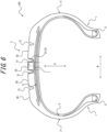
- the different-colored portion 87, as the indicator 8, may be simply colored on the surface of the tire 100, but as illustrated in FIG. 6 , is preferably formed from the surface of the tire 100 (in this embodiment, the outer surface of the sidewall portion 2) to within the tire 100.
- the different-colored portion 87, as the indicator 8 is preferably formed such that the different-colored material with a predetermined thickness is embedded in the surface of the tire 100. This can prevent a reduction in the distinguishability of the indicator 8, even when the tire 100 has been used to some extent and the surface is worn.
- the different-colored portion 87 may be formed even thicker than illustrated in FIG. 6 .
- the different-colored portion 87 may be formed over an area that is from a surface of the convex portion 30 to within the inside of the tread portion 3 in the radial direction R (within the tread portion 3) to a depth of valley bottoms of the concave portions 31 (a depth from the outer surface in the radial direction R).
- the indicator 8 According to the disposition of the indicator 8 illustrated in FIGS. 6 and 7 , a part of the indicator 8 is formed over the concave portions 31 so that, even when the convex portion 30 is heavily worn, the indicator 8 in the concave portions 31 remains. Therefore, the indicator 8 can be prevented from losing the distinguishability.
- the different-colored portion 87 is formed over an area that is from the outer surface of the tread portion 3 (the outer surface of the tire 100) to within the tire 100 and on the outer surface side (outside in the radial direction R) from the tag 7.
- the different-colored portion 87 as the indicator 8 is formed over the area that is from the outer surface of the tire 100 to within the tire 100 and on the outer surface side from the tag 7.
- the different-colored portion 87 may be formed over an area that encompasses (wraps) the tag 7.
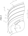
- FIG. 8 illustrates a case in which the different-colored portion 87 illustrated in the first embodiment is modified. Forming the different-colored portion 87 in this manner makes it possible, when the tag 7 is removed from the tire 100, to reliably remove the tag 7 by hollowing out or otherwise removing the entirety of the different-colored portion 87 using the difference in color as a guide.
- the indicator 8 may be disposed in such a position that the normal from the position of the tag 7 to the outer surface of the tire 100 closest from the tag 7 intersects the said outer surface.
- the indicator 8 may be disposed in such a position that the normal from the position of the tag 7 to the inner surface of the tire 100 closest to the tag 7 intersects the said inner surface.
- the indicator 8 may be formed in an area that includes the inner surface of the tire 100 and encompasses an orthogonal projection image of the outer shape of the tag 7 projected onto the inner surface of the tire 100.
- FIG. 9 illustrates a case in which the indicator 8 illustrated in the first embodiment is modified. That is, FIG.
- the indicator 8 can clearly indicate the area in which the tag 7 is embedded, even on the inner surface side of the tire 100. Therefore, the tag 7 can be removed from the tire 100 by hollowing out the tire 100 from the inner surface side.
- FIG. 9 illustrates the case in which the different-colored portion 87 and the second different-colored portion 88 are formed
- the different-colored portion 87 may not be formed and only the second different-colored portion 88 may be formed. This allows to indicate the area in which the tag 7 is embedded, without affecting the appearance and design of the tire 100 on the outer surface side.
- the above embodiments have illustrated only the cases in which the different-colored portion 87 and/or the second different-colored portion 88, as the indicator(s) 8, are/is disposed in such positions/a position that the normal from the position of the tag 7 to the surface(s) of the tire 100 closest to the tag 7 intersects the said surface(s).
- the above embodiments describe the cases in which the indicator(s) 8 indicate(s) the area in which the tag 7 is embedded.
- the indicator 8 may also include an auxiliary indicator that indicates the position at which the tag 7 is embedded, in addition to indicating the area in which the tag 7 is embedded.
- FIG. 10 illustrates a case in which an auxiliary indicator 81, as the indicator 8, is disposed at the same position as the tag 7 in the circumferential direction C of tire 100 and on the surface of tread portion 3.
- the example illustrated in FIG. 10 illustrates the case in which the auxiliary indicator 81 is disposed, in the tread portion 3, on a side closer to the tag 7 in the width direction W.
- the auxiliary indicator 81 further indicates which side in the width direction W the tag 7 is located.
- the different-colored portion 87 may be hidden by another adjacent tire.
- a worker can easily recognize the position of the tag 7 in the circumferential direction C of the tire 100 using, as a landmark, the auxiliary indicator 81 disposed at the same position as the tag 7 in the circumferential direction C of the tire 100, as long as the tread portion 3 is exposed and visible.
- using the position of the auxiliary indicator 81 in the width direction W as a clue it is easy to recognize which side of the tire 100 in the width direction W the tag 7 is located.
- directional indicators 89 as the indicators 8, that indicate the position of the tag 7 in the circumferential direction C may be disposed at different locations from the tag 7 in the circumferential direction C of the tire 100.
- FIG. 11 illustrates a case in which the directional indicators 89, 89 are disposed on the outer surface of the tread portion 3, one front and one back in the circumferential direction C of the tire 100 with respect to the same position as the tag 7 in the circumferential direction C of the tire 100.
- the directional indicators 89 are each formed as an arrow-like indication in the form of a triangle, for example, and indicate the position of the tag 7 in the circumferential direction C of the tire 100.
- the worker can thereby know the position of the tag 7 in the circumferential direction C of the tire 100 using the directional indicators 89, even when the different-colored portion 87 and the auxiliary indicator 81 are not exposed, and the worker can perform communication with the tag 7 or remove the tag 7 by easily recognizing the position of the different-colored portion 87, i.e., the position of the tag 7 by using these as a clue.
- the tag projection image 7s is the orthogonal projection image of the outer shape of the tag 7 projected onto the surface of the tire 100.
- the tag projection image 7s may be a projection image of the outer shape of the tag 7 projected at an included angle onto the surface of the tire 100, i.e., projected obliquely onto the surface of the tire 100.
- the different-colored portion 87, as the indicator 8, is preferably formed over an area that encompasses the tag 7.
- the present disclosure can be applied to tires.
Landscapes
- Engineering & Computer Science (AREA)
- Mechanical Engineering (AREA)
- Computer Hardware Design (AREA)
- Microelectronics & Electronic Packaging (AREA)
- Physics & Mathematics (AREA)
- General Physics & Mathematics (AREA)
- Theoretical Computer Science (AREA)
- Tires In General (AREA)
Abstract
Description
- The present disclosure relates to a tire.
- Patent Literature (PTL) 1 describes a pneumatic tire equipped with a transponder. The transponder is capable of providing various information regarding the tire and data on the tire in use. In this tire, the transponder has a transmitting and receiving function and a storage function, and is disposed, for example, on a sidewall portion. An identification label indicating the position of the transponder is provided on a tire outer surface of the sidewall portion on which the transponder is disposed or a tire outer surface of a sidewall portion on the opposite side of the sidewall portion on which the transponder is disposed. The identification label indicating the position of the transponder is distinguished from other portions based on color or shape. When the color of the identification label is different from the color of the tire outer surface, any of saturation, brightness, and hue may differ. When the identification label is in a three-dimensional shape, a concave shape depressed from the tire outer surface, a convex shape protruding from the tire outer surface, a combination of concave and convex shapes, or the like is employed.
-
PTL 2 describes a method for processing rubber materials including rubber from rubber-containing products such as tires. PTL 2 states that the rubber-containing products, such as tires, are processed by separating rubber from other materials. -
- PTL 1:
JP 2006-056443 A - PTL 2:
JP 2013-512134 A - For example, as described in
PTL 1, an electronic chip (so-called electronic tag or RFID tag, hereinafter simply referred to as "electronic tag") that functions as a transponder may be installed within a tire or on an inner surface of a tire. The electronic chip may then be able to provide information regarding the tire to an external terminal through communication with the electronic chip. This makes it easy to obtain a tire model, information on distribution and sales, a usage history, driving information on a vehicle on which the tire is mounted, and the like, to acquire, from the tire, information necessary for recycling the tire (e.g., information regarding constituent materials of the tire), and to manage traceability of the tire for proper disposal and recycling. Indicating the position of the electronic tag on an outer surface of the tire is convenient for acquiring information by a terminal device, which acquires information from the electronic tag, because where to hold a sensor can be recognized by the indication. It is also convenient when the electronic tag is separated from the tire in a separation process for disposal or recycling of the tire because the position of the electronic tag can be known. - Here, when the electronic tag is embedded within the tire, it may be necessary to hollow out the tire to remove and separate the electronic tag. Therefore, it is desirable to be able to recognize an area in which the electronic tag is installed, as the position of the electronic tag.
- The present disclosure is made in view of such circumstances. It would be helpful to provide a tire that can indicate an area in which an electronic tag is embedded.
- A tire according to the present disclosure to achieve the above object includes:
- an electronic tag disposed inside from a surface; and
- an indicator indicating the position of the electronic tag,
- wherein the indicator is:
- disposed in or on the surface, and
- formed in an area encompassing a projection image of the shape of the electronic tag onto the surface.
- According to the present disclosure, it is possible to provide a tire that can indicate an area in which an electronic tag is embedded.
- In the accompanying drawings:
-
FIG. 1 is a cross-sectional view of a tire according to a first embodiment, in a cross-section intersecting a circumferential direction of the tire and in a cross-section of a part including a tag and an indicator; -
FIG. 2 is a perspective view of the tire according to the first embodiment; -
FIG. 3 is an enlarged cross-sectional view of a part of a sidewall portion, in the cross-sectional view ofFIG. 1 ; -
FIG. 4 is a schematic diagram illustrating the positional relationship between the tag and the indicator; -
FIG. 5 is an enlarged diagram ofFIG. 2 , which illustrates, with enlargement, the vicinity of the indicator disposed in the sidewall portion; -
FIG. 6 is a cross-sectional view of a tire according to a second embodiment, in a cross-section intersecting a circumferential direction of the tire and in a cross-section of a part including an indicator; -
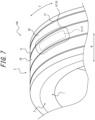
FIG. 7 is a perspective view of the tire according to the second embodiment; -
FIG. 8 is an enlarged cross-sectional view in which a part of the sidewall portion of the tire with an indicator ofVariation 1 is enlarged; -
FIG. 9 is an enlarged cross-sectional view in which a part of the sidewall portion of the tire with an indicator ofVariation 2 is enlarged; -
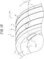
FIG. 10 is a diagram illustrating, with enlargement, the vicinity of an indicator in a sidewall portion of another tire; and -
FIG. 11 is a perspective view of another tire. - Tires according to embodiments of the present disclosure will be described based on the drawings.
-
FIGS. 1 and2 illustrate atire 100 of this embodiment.FIG. 1 illustrates a cross-section of thetire 100 intersecting a circumferential direction C (seeFIG. 2). FIG. 2 is a perspective view of thetire 100. As illustrated inFIG. 1 , thetire 100 includes an electronic tag 7 (hereinafter referred to as tag 7) disposed inside from a surface of thetire 100, and anindicator 8 indicating the position of thetag 7. One example of thetag 7 is a so-called RFID tag, which is an electronic circuit device or electronic chip that includes an antenna circuit for establishing communication, a storage circuit, and a control circuit. Thetire 100 will be described in detail below. - As illustrated in
FIGS. 1 and2 , thetire 100 includesbead portions 1, which are disposed on the sides of thetire 100 and secure thetire 100 to a rim,sidewall portions 2, which constitute the sides of thetire 100, and atread portion 3, which contacts a road surface. - As illustrated in
FIG. 2 , thetire 100 is formed in the shape of an approximately circular annulus centered on an axial center G. That is, thetread portion 3, thesidewall portions 2, and thebead portions 1 are in the shapes of approximately circular annuluses that are centered in common on the axial center G. - In the following description, a width direction W, the circumferential direction C (see
FIG. 2 ), and a radial direction R of thetire 100 illustrated inFIGS. 1 and2 have the same meaning as a width direction, a circumferential direction, and a radial direction of thetread portion 3. In the radial direction R, an outside of the annulus is referred to as a radial outside, and an inside of the annulus is referred to as a radial inside. - As illustrated in
FIG. 1 , thetire 100 includes, as its internal structure, a carcass 5, which is a cord layer forming a skeleton of thetire 100,bead cores 4, which are internal skeletons of thebead portions 1 and support the carcass 5, and belts 6, which are reinforcement belts stretched along the circumferential direction C between a surface of thetread portion 3 and the carcass 5. - The
bead portions 1, thesidewall portions 2, and thetread portion 3 each contain synthetic rubber. The synthetic rubber of thebead portions 1 and thesidewall portions 2 is referred to as side rubber. The synthetic rubber of thetread portion 3 is referred to as tread rubber. Thebead cores 4, the carcass 5, and the belts 6 are embedded in the side rubber and the tread rubber. In thetire 100, radial outside ends of thesidewall portions 2 are integrally connected to both ends of thetread portion 3 in the width direction W. Thebead portions 1 are integrally connected to radial inside ends of thesidewall portions 2. In other words, the cross-section of thetire 100 intersecting the circumferential direction C is in the shape of the letter C of the alphabet. The surface of thetire 100 in this embodiment refers to an outside surface (hereinafter also referred to as outer surface) and an inside surface (hereinafter also referred to as inner surface) of the C-shaped arc in the C-shape of thetire 100. - As illustrated in
FIGS. 1 and2 , thetread portion 3 is formed with a tread pattern, which has a plurality of convex portions 30 (an example of a tread surface) whose outer circumferential surfaces contact the road surface and a plurality ofconcave portions 31 that is concave radially inside relative to theconvex portions 30. Theconcave portions 31 are, for example, circumferential grooves. Note that, the outer circumferential surfaces constitute a radial outside surface of thetread portion 3 in thetire 100. - The
tire 100 in this embodiment further includes thetag 7 and theindicator 8, as described above. The cross-section of thetire 100 illustrated inFIG. 1 is a cross-section of thetire 100 viewed along the circumferential direction C (seeFIG. 2 ), and is a cross-section of a part including thetag 7 and theindicator 8. -
FIGS. 1 and2 illustrate a case in which thetag 7 is disposed within the tire 100 (inside from the surface), on a side closer to thebead portion 1 in one of thesidewall portions 2, and is disposed outside from the carcass 5 (seeFIG. 2 ) in the width direction W of thetire 100. In other words, thetag 7 is embedded (disposed) in the side of thetire 100. Note that, the outside in the width direction W refers to the same side as thesidewall portion 2 side, viewed from thetread portion 3. -
FIG. 3 illustrates an enlarged cross-sectional view of a part of thesidewall portion 2, in the cross-sectional view illustrated inFIG. 1 . As illustrated inFIG. 3 , theindicator 8 is formed in thesidewall portion 2. - As illustrated in
FIG. 3 , theindicator 8 is disposed in such a position that the normal from the position of thetag 7 to an outer surface of thesidewall portion 2, which is the outer surface of thetire 100 closest to thetag 7, intersects the said outer surface. This allows theindicator 8 to clearly indicate an area in which thetag 7 is embedded. This facilitates removal of thetag 7 when thetire 100 is disposed of or recycled. In a case in which a worker performs communication with thetag 7 using a terminal device, theindicator 8 can indicate the position of thetag 7 to the worker, so that the worker can easily recognize the position of thetag 7 and smoothly perform communication with thetag 7. - The position of the
indicator 8 will be described in detail based onFIGS. 2 ,4 , and5 .FIG. 4 is a schematic diagram illustrating the positional relationship between thetag 7 and theindicator 8, for the purpose of illustrating the position of installation of theindicator 8.FIG. 5 is an enlarged diagram ofFIG. 2 , which illustrates, with enlargement, the vicinity of theindicator 8 disposed in thesidewall portion 2. InFIGS. 2 ,4 and5 , an orthogonal projection image (an example of a projection image) of the outer shape of thetag 7 projected onto the outer surface of thesidewall portion 2 is illustrated as atag projection image 7s. As illustrated inFIG. 4 , in this embodiment, theindicator 8 is formed in an area that includes the outer surface of thesidewall portion 2 and encompasses thetag projection image 7s. In this embodiment, the orthogonal projection image of the outer shape of thetag 7 projected onto the surface of thesidewall portion 2, i.e. thetag projection image 7s is an image of projecting the outer shape of thetag 7 onto the surface of thetire 100 closest to the center of the tag 7 (in this embodiment, the outer surface of the sidewall portion 2), in a direction along the normal from the center of thetag 7 to the said outer surface. - The
indicator 8 may be formed in the area that encompasses thetag projection image 7s (seeFIGS. 2 and4 ) on the surface of thetire 100, as illustrated inFIGS. 3 to 5 . The position of embedment of thetag 7 within thetire 100 can be thereby indicated in a direction orthogonal to the surface of thetire 100. In other words, thetag 7 can be removed from thetire 100 by hollowing out the tire 100 (in this embodiment, the sidewall portion 2) in a direction orthogonal to the surface. - As illustrated in
FIGS. 3 to 5 , theindicator 8 is preferably formed, in the surface of thetire 100, in an area that encompasses thetag projection image 7s (seeFIGS. 2 and4 ) and is wider than thetag projection image 7s. This makes it possible, when thetag 7 is removed from thetire 100, to remove thetag 7 from thetire 100 more reliably by hollowing out the area in which theindicator 8 is formed. In other words, thetag 7 can be reliably removed using the entire area indicated by theindicator 8 as an object of separation. - The
indicator 8 is preferably formed of a material (different-colored material) with a different color from the other parts in thetread portion 3. This allows the indication of theindicator 8 to be clearly distinguished by the difference in color. The different color means that there is a difference in saturation, tone, brightness, pattern, gloss, or the like, such that the difference can be visually recognized, i.e., there is visual distinguishability. The different-colored material includes materials that emit or store light. This embodiment illustrates a case in which a different-colored portion 87 is formed as theindicator 8. The different-colored material may be made by adding, to rubber, pigment of a different color from the other parts, or by removing carbon from rubber. - In addition to providing the visual distinguishability of the position or area using the different color from the other parts in the
tread portion 3, theindicator 8 may also indicate the depth of embedment of thetag 7 by its color (saturation, tone, brightness, pattern, gloss, or the like). This can indicate how deep thetag 7 is embedded from the surface of thetire 100. In other words, thetag 7 can be removed from thetire 100 by hollowing out thetire 100 to the depth indicated by theindicator 8. For example, when theindicator 8 is yellow, the depth is 1 mm or more and less than 5 mm from the surface, and when theindicator 8 is blue, the depth is 5 mm or more and less than 15 mm from the surface. - In addition to indicating the depth of embedment of the
tag 7 by its color (saturation, tone, brightness, pattern, gloss, or the like), theindicator 8 may also indicate the depth of embedment of thetag 7 by its shape. For example, when theindicator 8 is drawn as a double ellipse, the depth is 1 mm or more and less than 5 mm from the surface, and when theindicator 8 is drawn as a double rectangle, the depth is 5 mm or more and less than 15 mm from the surface. - The different-
colored portion 87, as theindicator 8, may be simply colored on the surface of thetire 100, but as illustrated inFIG. 3 , is preferably formed from the surface of the tire 100 (in this embodiment, the outer surface of the sidewall portion 2) to within thetire 100. In other words, the different-colored portion 87, as theindicator 8, is preferably formed such that the different-colored material with a predetermined thickness is embedded in the surface of thetire 100. This can prevent a reduction in the distinguishability of theindicator 8, even when thetire 100 has been used to some extent and the surface is worn. - In this embodiment, the different-
colored portion 87 is formed over an area that is from the outer surface of the sidewall portion 2 (the outer surface of the tire 100) to within thetire 100 and on the outer surface side (in this embodiment, outside in the width direction W) from thetag 7. - A
tire 100 according to a second embodiment is different from thetire 100 according to the first embodiment in the disposition of thetag 7 and theindicator 8, and is otherwise the same. - In the
tire 100 according to this embodiment, as illustrated inFIGS. 6 and7 , thetag 7 is embedded within thetire 100 in thetread portion 3 and outside from the carcass 5 in the radial direction R. - As illustrated in
FIGS. 6 and7 , theindicator 8 is disposed in such a position that the normal from the position of thetag 7 to an outer surface of thetread portion 3, which is the outer surface of thetire 100 closest to thetag 7, intersects the said outer surface. In this embodiment, the different-colored portion 87, as theindicator 8, is disposed over an area that encompasses thetag projection image 7s (seeFIG. 7 ) and is wider than thetag projection image 7s. In other words, as illustrated inFIG. 7 , the different-colored portion 87 is disposed over the wider area than thetag projection image 7s in the circumferential direction C and the width direction W. In this embodiment, the different-colored portion 87 is disposed, in the width direction W, over a middleconvex portion 30 of thetread portion 3, in which thetag projection image 7s is positioned, andconcave portions 31 on both sides of the saidconvex portion 30 in the width direction W. - The different-
colored portion 87, as theindicator 8, may be simply colored on the surface of thetire 100, but as illustrated inFIG. 6 , is preferably formed from the surface of the tire 100 (in this embodiment, the outer surface of the sidewall portion 2) to within thetire 100. In other words, the different-colored portion 87, as theindicator 8, is preferably formed such that the different-colored material with a predetermined thickness is embedded in the surface of thetire 100. This can prevent a reduction in the distinguishability of theindicator 8, even when thetire 100 has been used to some extent and the surface is worn. - The different-
colored portion 87 may be formed even thicker than illustrated inFIG. 6 . The thicker the different-colored portion 87 is formed, the more distinguishability of theindicator 8 can be maintained even when thetire 100 is worn. For example, the different-colored portion 87 may be formed over an area that is from a surface of theconvex portion 30 to within the inside of thetread portion 3 in the radial direction R (within the tread portion 3) to a depth of valley bottoms of the concave portions 31 (a depth from the outer surface in the radial direction R). - According to the disposition of the
indicator 8 illustrated inFIGS. 6 and7 , a part of theindicator 8 is formed over theconcave portions 31 so that, even when theconvex portion 30 is heavily worn, theindicator 8 in theconcave portions 31 remains. Therefore, theindicator 8 can be prevented from losing the distinguishability. - In this embodiment, the different-
colored portion 87 is formed over an area that is from the outer surface of the tread portion 3 (the outer surface of the tire 100) to within thetire 100 and on the outer surface side (outside in the radial direction R) from thetag 7. - Variations of the above embodiments will be described below.
- The above embodiments describe the cases in which the different-
colored portion 87, as theindicator 8, is formed over the area that is from the outer surface of thetire 100 to within thetire 100 and on the outer surface side from thetag 7. However, as illustrated inFIG. 8 , the different-colored portion 87 may be formed over an area that encompasses (wraps) thetag 7.FIG. 8 illustrates a case in which the different-colored portion 87 illustrated in the first embodiment is modified. Forming the different-colored portion 87 in this manner makes it possible, when thetag 7 is removed from thetire 100, to reliably remove thetag 7 by hollowing out or otherwise removing the entirety of the different-colored portion 87 using the difference in color as a guide. - The above embodiments describe the cases in which the
indicator 8 is disposed in such a position that the normal from the position of thetag 7 to the outer surface of thetire 100 closest from thetag 7 intersects the said outer surface. However, theindicator 8 may be disposed in such a position that the normal from the position of thetag 7 to the inner surface of thetire 100 closest to thetag 7 intersects the said inner surface. Specifically, as illustrated inFIG. 9 , theindicator 8 may be formed in an area that includes the inner surface of thetire 100 and encompasses an orthogonal projection image of the outer shape of thetag 7 projected onto the inner surface of thetire 100.FIG. 9 illustrates a case in which theindicator 8 illustrated in the first embodiment is modified. That is,FIG. 9 illustrates the case of forming the different-colored portion 87, as theindicator 8, formed on the outer surface of thetire 100 and a second different-colored portion 88, as theindicator 8, formed on the inner surface of thetire 100. Owing to the second different-colored portion 88, theindicator 8 can clearly indicate the area in which thetag 7 is embedded, even on the inner surface side of thetire 100. Therefore, thetag 7 can be removed from thetire 100 by hollowing out thetire 100 from the inner surface side. - Although
FIG. 9 illustrates the case in which the different-colored portion 87 and the second different-colored portion 88 are formed, the different-colored portion 87 may not be formed and only the second different-colored portion 88 may be formed. This allows to indicate the area in which thetag 7 is embedded, without affecting the appearance and design of thetire 100 on the outer surface side. - As described above, it is possible to indicate the area in which the electronic tag installed in the tire is embedded.
- (1) The above embodiments have illustrated only the cases in which the different-
colored portion 87 and/or the second different-colored portion 88, as the indicator(s) 8, are/is disposed in such positions/a position that the normal from the position of thetag 7 to the surface(s) of thetire 100 closest to thetag 7 intersects the said surface(s). The above embodiments describe the cases in which the indicator(s) 8 indicate(s) the area in which thetag 7 is embedded. However, theindicator 8 may also include an auxiliary indicator that indicates the position at which thetag 7 is embedded, in addition to indicating the area in which thetag 7 is embedded. -
FIG. 10 illustrates a case in which anauxiliary indicator 81, as theindicator 8, is disposed at the same position as thetag 7 in the circumferential direction C oftire 100 and on the surface oftread portion 3. This allows theauxiliary indicator 81, as theindicator 8, to indicate the position of thetag 7 in the circumferential direction C of thetire 100. Note that, the example illustrated inFIG. 10 illustrates the case in which theauxiliary indicator 81 is disposed, in thetread portion 3, on a side closer to thetag 7 in the width direction W. Thereby, theauxiliary indicator 81 further indicates which side in the width direction W thetag 7 is located. - For example, as illustrated in the first embodiment described above, in a case in which the
tag 7 is located on the side of thetire 100, for example, whentires 100 are stacked flat, the different-colored portion 87 may be hidden by another adjacent tire. However, by providing theauxiliary indicator 81 on thetread portion 3 too, a worker can easily recognize the position of thetag 7 in the circumferential direction C of thetire 100 using, as a landmark, theauxiliary indicator 81 disposed at the same position as thetag 7 in the circumferential direction C of thetire 100, as long as thetread portion 3 is exposed and visible. Also, using the position of theauxiliary indicator 81 in the width direction W as a clue, it is easy to recognize which side of thetire 100 in the width direction W thetag 7 is located. This further facilitates removal of thetag 7 when thetire 100 is disposed of or recycled. In a case in which the worker performs communication with thetag 7, the worker can easily recognize the position of the different-colored portion 87, i.e., the position of thetag 7, using theauxiliary indicator 81 as a clue, and can smoothly perform communication with thetag 7. - As illustrated in
FIG. 11 ,directional indicators 89, as theindicators 8, that indicate the position of thetag 7 in the circumferential direction C may be disposed at different locations from thetag 7 in the circumferential direction C of thetire 100. - The example illustrated in
FIG. 11 illustrates a case in which thedirectional indicators tread portion 3, one front and one back in the circumferential direction C of thetire 100 with respect to the same position as thetag 7 in the circumferential direction C of thetire 100. Thedirectional indicators 89 are each formed as an arrow-like indication in the form of a triangle, for example, and indicate the position of thetag 7 in the circumferential direction C of thetire 100. The worker can thereby know the position of thetag 7 in the circumferential direction C of thetire 100 using thedirectional indicators 89, even when the different-colored portion 87 and theauxiliary indicator 81 are not exposed, and the worker can perform communication with thetag 7 or remove thetag 7 by easily recognizing the position of the different-colored portion 87, i.e., the position of thetag 7 by using these as a clue. - (2) The above embodiments describe the cases in which the
tag 7 is embedded in thetire 100, but a part of thetag 7 may be exposed from the inner surface of thetire 100. Even in this case, the different-colored portion 87 or the second different-colored portion 88, as theindicator 8, can indicate the area in which thetag 7 is embedded. - (3) The above embodiments exemplarily describe the cases in which the
tag projection image 7s is the orthogonal projection image of the outer shape of thetag 7 projected onto the surface of thetire 100. However, thetag projection image 7s may be a projection image of the outer shape of thetag 7 projected at an included angle onto the surface of thetire 100, i.e., projected obliquely onto the surface of thetire 100. In this case, the different-colored portion 87, as theindicator 8, is preferably formed over an area that encompasses thetag 7. - The configurations disclosed in each of the above embodiments (including the other embodiments, the same hereinafter) can be applied in combination with the configurations disclosed in the other embodiments, as long as no contradiction arises. The embodiments disclosed in this specification are just examples. The embodiments of the present disclosure are not limited thereto, and may be modified as appropriate within the scope not departing from the purpose of the present disclosure.
- The present disclosure can be applied to tires.
-
- 1
- bead portion
- 100
- tire
- 2
- sidewall portion
- 3
- tread portion
- 30
- convex portion
- 31
- concave portion
- 38
- different-shaped portion
- 4
- bead core
- 5
- carcass
- 6
- belt
- 7
- tag (electronic tag)
- 8
- indicator
- 81
- auxiliary indicator
- 87
- different-colored portion
- 88
- second different-colored portion
- 89
- directional indicator
- C
- circumferential direction
- R
- radial direction
- W
- width direction
Claims (5)
- A tire comprising:an electronic tag disposed inside from a surface; andan indicator indicating a position of the electronic tag,wherein the indicator is:disposed in or on the surface, andformed in an area encompassing a projection image of a shape of the electronic tag onto the surface.
- The tire according to claim 1, wherein the indicator is formed in an area encompassing an orthogonal projection image of the shape of the electronic tag onto the surface.
- The tire according to claim 1 or 2, wherein the indicator indicates a depth of embedment of the electronic tag.
- The tire according to any one of claims 1 to 3, wherein the indicator is formed over an area encompassing the electronic tag.
- The tire according to any one of claims 1 to 4, wherein the indicator includes an auxiliary indicator indicating the position of the electronic tag in the circumferential direction.
Applications Claiming Priority (2)
| Application Number | Priority Date | Filing Date | Title |
|---|---|---|---|
| JP2021200154A JP7701867B2 (en) | 2021-12-09 | 2021-12-09 | tire |
| PCT/JP2022/019975 WO2023105812A1 (en) | 2021-12-09 | 2022-05-11 | Tire |
Publications (2)
| Publication Number | Publication Date |
|---|---|
| EP4446131A1 true EP4446131A1 (en) | 2024-10-16 |
| EP4446131A4 EP4446131A4 (en) | 2025-03-26 |
Family
ID=86730004
Family Applications (1)
| Application Number | Title | Priority Date | Filing Date |
|---|---|---|---|
| EP22903750.2A Pending EP4446131A4 (en) | 2021-12-09 | 2022-05-11 | TIRE |
Country Status (5)
| Country | Link |
|---|---|
| US (1) | US12605973B2 (en) |
| EP (1) | EP4446131A4 (en) |
| JP (1) | JP7701867B2 (en) |
| CN (1) | CN118265616A (en) |
| WO (1) | WO2023105812A1 (en) |
Cited By (1)
| Publication number | Priority date | Publication date | Assignee | Title |
|---|---|---|---|---|
| EP4635757A4 (en) * | 2022-12-12 | 2026-04-29 | Bridgestone Corp | TIRES |
Families Citing this family (1)
| Publication number | Priority date | Publication date | Assignee | Title |
|---|---|---|---|---|
| JP2024084053A (en) * | 2022-12-12 | 2024-06-24 | 株式会社ブリヂストン | tire |
Family Cites Families (12)
| Publication number | Priority date | Publication date | Assignee | Title |
|---|---|---|---|---|
| JP4505991B2 (en) | 2001-01-09 | 2010-07-21 | 横浜ゴム株式会社 | Pneumatic tire with transponder |
| JP4204845B2 (en) * | 2002-10-30 | 2009-01-07 | 株式会社ブリヂストン | Pneumatic tire provided with electronic chip and manufacturing method thereof |
| JP4922561B2 (en) | 2002-12-23 | 2012-04-25 | ブリヂストン アメリカズ タイヤ オペレイションズ エルエルシー | Tire with tag |
| JPWO2005095127A1 (en) | 2004-03-31 | 2008-02-21 | 株式会社ブリヂストン | Wireless IC tag mounting holder and tire with wireless IC tag |
| JP4487125B2 (en) | 2004-08-23 | 2010-06-23 | 横浜ゴム株式会社 | Pneumatic tire |
| US8686834B2 (en) * | 2007-11-20 | 2014-04-01 | Samsung Electronics Co., Ltd. | Terminal having radio frequency function and method of processing information of the terminal |
| US8091808B2 (en) | 2008-06-02 | 2012-01-10 | Entyrecycle, Llc | Redundant tire and rubber compound reprocessing |
| US9827724B2 (en) | 2013-09-17 | 2017-11-28 | Bridgestone Americas Tire Operations, Llc | Tire structure for externally mounted device |
| US10766317B2 (en) | 2013-12-06 | 2020-09-08 | The Yokohama Rubber Co., Ltd. | Pneumatic tire |
| US10977680B2 (en) * | 2016-11-13 | 2021-04-13 | Talkin Things Sp . Z O.O. | Geo-localization purchase incentive system |
| DE102018202249A1 (en) * | 2018-02-14 | 2019-08-14 | Continental Reifen Deutschland Gmbh | vehicle tires |
| US10919348B2 (en) * | 2018-09-05 | 2021-02-16 | The Goodyear Tire & Rubber Company | Tire with RFID locator |
-
2021
- 2021-12-09 JP JP2021200154A patent/JP7701867B2/en active Active
-
2022
- 2022-05-11 CN CN202280074881.4A patent/CN118265616A/en active Pending
- 2022-05-11 WO PCT/JP2022/019975 patent/WO2023105812A1/en not_active Ceased
- 2022-05-11 US US18/707,882 patent/US12605973B2/en active Active
- 2022-05-11 EP EP22903750.2A patent/EP4446131A4/en active Pending
Cited By (1)
| Publication number | Priority date | Publication date | Assignee | Title |
|---|---|---|---|---|
| EP4635757A4 (en) * | 2022-12-12 | 2026-04-29 | Bridgestone Corp | TIRES |
Also Published As
| Publication number | Publication date |
|---|---|
| JP2023085866A (en) | 2023-06-21 |
| JP7701867B2 (en) | 2025-07-02 |
| WO2023105812A1 (en) | 2023-06-15 |
| EP4446131A4 (en) | 2025-03-26 |
| CN118265616A (en) | 2024-06-28 |
| US20250170859A1 (en) | 2025-05-29 |
| US12605973B2 (en) | 2026-04-21 |
Similar Documents
| Publication | Publication Date | Title |
|---|---|---|
| US12605973B2 (en) | Tire | |
| US10919348B2 (en) | Tire with RFID locator | |
| CN100560386C (en) | pneumatic tire | |
| KR101149802B1 (en) | Use of colored indica on tires as designator | |
| US10766317B2 (en) | Pneumatic tire | |
| EP0490247A1 (en) | Character for a tire | |
| WO2012035690A1 (en) | Tire | |
| US11897292B2 (en) | Pneumatic tire | |
| JP2014125119A (en) | Pneumatic tire | |
| JP7732876B2 (en) | tire | |
| US11661209B2 (en) | Increased visibility of indicating markers in a structure and associated system and method | |
| KR102463584B1 (en) | A pneumatic tire with indicator groove | |
| JP7732875B2 (en) | tire | |
| US12397592B2 (en) | Tire | |
| US9346327B2 (en) | Pneumatic tire | |
| EP4446136B1 (en) | Tire | |
| WO2024135826A1 (en) | Tire | |
| JPH04275136A (en) | Preparation of pneumatic tire | |
| JP2012116217A (en) | Tire | |
| JP2000326708A (en) | Pneumatic tire | |
| CN119682444A (en) | Pneumatic tires | |
| JP2004082974A (en) | Pneumatic tire | |
| KR20240051408A (en) | Tire wiht detachable rfid tags | |
| JP2024172036A (en) | Pneumatic tires | |
| JPH09295503A (en) | Pneumatic tire and pneumatic tire-rim assembly |
Legal Events
| Date | Code | Title | Description |
|---|---|---|---|
| STAA | Information on the status of an ep patent application or granted ep patent |
Free format text: STATUS: THE INTERNATIONAL PUBLICATION HAS BEEN MADE |
|
| PUAI | Public reference made under article 153(3) epc to a published international application that has entered the european phase |
Free format text: ORIGINAL CODE: 0009012 |
|
| STAA | Information on the status of an ep patent application or granted ep patent |
Free format text: STATUS: REQUEST FOR EXAMINATION WAS MADE |
|
| 17P | Request for examination filed |
Effective date: 20240229 |
|
| AK | Designated contracting states |
Kind code of ref document: A1 Designated state(s): AL AT BE BG CH CY CZ DE DK EE ES FI FR GB GR HR HU IE IS IT LI LT LU LV MC MK MT NL NO PL PT RO RS SE SI SK SM TR |
|
| DAV | Request for validation of the european patent (deleted) | ||
| DAX | Request for extension of the european patent (deleted) | ||
| A4 | Supplementary search report drawn up and despatched |
Effective date: 20250225 |
|
| RIC1 | Information provided on ipc code assigned before grant |
Ipc: B60C 23/04 20060101ALI20250219BHEP Ipc: G06K 19/077 20060101ALI20250219BHEP Ipc: B60C 19/00 20060101ALI20250219BHEP Ipc: B60C 15/00 20060101ALI20250219BHEP Ipc: B60C 11/00 20060101ALI20250219BHEP Ipc: B60C 13/00 20060101AFI20250219BHEP |
|
| STAA | Information on the status of an ep patent application or granted ep patent |
Free format text: STATUS: EXAMINATION IS IN PROGRESS |
|
| 17Q | First examination report despatched |
Effective date: 20251217 |