EP4443201A1 - Sicherheitsfilm mit hoher helligkeit - Google Patents
Sicherheitsfilm mit hoher helligkeit Download PDFInfo
- Publication number
- EP4443201A1 EP4443201A1 EP22901647.2A EP22901647A EP4443201A1 EP 4443201 A1 EP4443201 A1 EP 4443201A1 EP 22901647 A EP22901647 A EP 22901647A EP 4443201 A1 EP4443201 A1 EP 4443201A1
- Authority
- EP
- European Patent Office
- Prior art keywords
- light
- security film
- shielding
- incident
- light transmitting
- Prior art date
- Legal status (The legal status is an assumption and is not a legal conclusion. Google has not performed a legal analysis and makes no representation as to the accuracy of the status listed.)
- Pending
Links
Images




Classifications
-
- G—PHYSICS
- G02—OPTICS
- G02B—OPTICAL ELEMENTS, SYSTEMS OR APPARATUS
- G02B5/00—Optical elements other than lenses
- G02B5/30—Polarising elements
- G02B5/3025—Polarisers, i.e. arrangements capable of producing a definite output polarisation state from an unpolarised input state
- G02B5/3066—Polarisers, i.e. arrangements capable of producing a definite output polarisation state from an unpolarised input state involving the reflection of light at a particular angle of incidence, e.g. Brewster's angle
-
- G—PHYSICS
- G02—OPTICS
- G02B—OPTICAL ELEMENTS, SYSTEMS OR APPARATUS
- G02B27/00—Optical systems or apparatus not provided for by any of the groups G02B1/00 - G02B26/00, G02B30/00
- G02B27/09—Beam shaping, e.g. changing the cross-sectional area, not otherwise provided for
- G02B27/0938—Using specific optical elements
- G02B27/0988—Diaphragms, spatial filters, masks for removing or filtering a part of the beam
-
- G—PHYSICS
- G02—OPTICS
- G02B—OPTICAL ELEMENTS, SYSTEMS OR APPARATUS
- G02B5/00—Optical elements other than lenses
- G02B5/003—Light absorbing elements
-
- G—PHYSICS
- G02—OPTICS
- G02B—OPTICAL ELEMENTS, SYSTEMS OR APPARATUS
- G02B5/00—Optical elements other than lenses
- G02B5/30—Polarising elements
- G02B5/3025—Polarisers, i.e. arrangements capable of producing a definite output polarisation state from an unpolarised input state
- G02B5/3033—Polarisers, i.e. arrangements capable of producing a definite output polarisation state from an unpolarised input state in the form of a thin sheet or foil, e.g. Polaroid
-
- G—PHYSICS
- G02—OPTICS
- G02B—OPTICAL ELEMENTS, SYSTEMS OR APPARATUS
- G02B2207/00—Coding scheme for general features or characteristics of optical elements and systems of subclass G02B, but not including elements and systems which would be classified in G02B6/00 and subgroups
- G02B2207/123—Optical louvre elements, e.g. for directional light blocking
Definitions
- the present invention relates to a high-brightness security film, and more specifically, to a security film in which brightness and clarity are improved by improving light transmittance.
- display screens of smartphones and laptops have wide viewing angles and high clarity and are widely used.
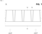
- FIG. 1 is a cross-sectional view of a conventional security film.
- a conventional security film 10 has a structure in which a transmitting area 12 formed of a transparent material on a base film 11 and through which light is transmitted, and a shielding area 13 formed of a black material and through which light is blocked are repeatedly arranged.
- the shielding area 13 has a trapezoidal cross-sectional shape, a flat bottom surface, and angled corners, and a viewing angle displayed on the screen is determined according to the relationship between the width of the transmitting area 12 and the depth of the shielding area 13 and thus the user can recognize the screen content according to the viewing angle.
- the screen content is visible within a viewing angle set from 0 degrees in a vertical direction of a front surface of the security film 10, and the screen becomes dark beyond the viewing angle, achieving the effect of shielding the screen content.
- the conventional security film 10 has a problem in that the brightness of the screen becomes dark because some of light incident on the security film 10 is blocked by the shielding area 13.
- light incident on the light-incident side end of the shielding area 13 may not be reflected to the transmitting area 12 and may be lost by absorption or reflection due to the characteristic that a surface of an incident surface side of the shielding area 13 has a flat structure, and light may not be emitted from the light-emitting surface due to total reflection, or the like due to a surface of the light-emitting surface side of the transmitting area 12 also being formed flat, thereby causing a problem of decreased light transmittance.
- the shielding portion may include a first side surface portion that in in contact with the light transmitting portion and extends in a thickness direction of the pattern layer, an inner end portion forming an end of the light-incident surface side of the shielding portion, and a first curved portion formed at a portion where the inner end portion and the first side surface portion are connected and configured to be curved in a round shape, wherein light reflected from the first curved portion may be guided toward the light transmitting portion.
- the inner end portion may be formed as a flat surface.
- the inner end portion may be formed to be curved in a round shape.
- a radius of curvature of the first curved portion may be formed to be different from a radius of curvature of the inner end portion.
- At least a portion of a light-emitting surface of the light transmitting portion may be rounded so that light reflected from an inner side surface of the light-emitting surface of the light transmitting portion may be transmitted to the outside of the light-emitting surface of the light transmitting portion.
- the light-emitting surface of the light transmitting portion may be formed to protrude further outward than the shielding portion.
- the light transmitting portion may include a second side surface portion that is in contact with the shielding portion and extends in the thickness direction of the pattern layer, an outer end portion forming an end of the light-emitting surface of the light transmitting portion, and a second curved portion formed at a portion where the second side surface portion and the outer end portion are connected and configured to be curved in a round shape.
- the second curved portion may be formed with a radius of curvature greater than 0 ⁇ m and less than or equal to 100 ⁇ m.
- the outer end portion may be formed as a flat surface.
- the outer end portion may be formed to be curved in a round shape.
- the radius of curvature of the second curved portion may be formed to be different from the radius of curvature of the outer end portion.
- a radius of curvature of the second curved portion may be formed to be smaller than a radius of curvature of the outer end portion.
- the resin of the shielding portion may be formed with a refractive index smaller than that of the light transmitting portion.
- a security film includes a base layer formed of a light-transmitting material, and a pattern layer including light transmitting portions which are formed of a light-transmitting material through which light incident from the base layer is transmitted and are spaced apart at predetermined intervals, and shielding portions which are formed between the spaced-apart light transmitting portions and include a resin and shielding particles dispersed in the resin so as to block the light incident through the base layer, wherein the pattern layer may limit a viewing angle by transmitting some of the light incident from the base layer, and in the pattern layer, at least a portion of a surface of a light-incident surface side of the shielding portion in a direction in which light is incident or a surface of a light-emitting surface side of the light transmitting portion in a direction in which light is emitted is rounded to improve light transmittance.
- the shielding portion may include a first side surface portion that is in contact with the light transmitting portion and extends in the thickness direction of the pattern layer, an inner end portion forming an end of the light-incident surface side of the shielding portion, and a first curved portion formed at a portion where the inner end portion and the first side surface portion are connected and configured to be curved in a round shape, and the light-emitting surface of the light transmitting portion may be formed to protrude further outward than the shielding portion.
- the light transmitting portion may be formed with a greater refractive index than a refractive index of a material in contact with an outer side of the light-emitting surface of the light transmitting portion.
- the security film may further include a base portion disposed between the base layer and the pattern layer and formed of a light-transmitting material.
- a high-brightness security film of the present invention since some of the light incident on the surface of the light-incident surface of a shielding portion among the light flowing into the security film is reflected toward the light transmitting portion light is not lost and thus light transmittance can be improved.
- light transmittance can be improved by minimizing light that does not pass through the light-emitting surface due to total reflection, or the like on the light-emitting surface of the light transmitting portion.
- FIGS. 2 to 5 a security film according to one embodiment of the present invention will be described with reference to FIGS. 2 to 5 .
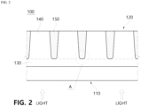
- a security film 100 may include a base layer 110 and a pattern layer 120.
- the base layer 110 may be formed of a film material such as a light-transmitting polymer.
- the base layer 110 as described above may be provided on a light-incident side where light is incident and may be in contact with or attached to a surface of a display, etc.
- the pattern layer 120 may be formed on the base layer 110, and may include a base portion 130 through which light passing through the base layer 110 is incident, and a light transmitting portion 140 through which the light incident from the base portion 130 is transmitted, and a shielding portion 150 that is arranged alternately with the light transmitting portion 140 and blocks light, and may be provided to limit a viewing angle by blocking and transmitting some of the light incident from the base layer 110.
- the shielding portion 150 based on a traveling direction of light within the security film 100, may be formed with a trapezoidal cross-section where a width of the light-emitting side is wider than a width of the light-incident side, or a rectangular cross-section with a width of the light-incident side is the same as a width of the light-emitting side.
- the light transmitting portion 140 and the shielding portion 150 may extend long in a predetermined direction along a surface of a plane when viewed from the plane.
- the shielding portion 150 may include a first side surface portion 151, an inner end portion 154, and a first curved portion 156.
- the first side surface portion 151 may form a side surface of the shielding portion 150, may be in contact with the light transmitting portion 140, and may extend in a thickness direction of the pattern layer 120.
- the inner end portion 154 may be formed round with the same radius of curvature as the first curved portion 156 or may be formed round with a radius of curvature different from that of the first curved portion 156 to induce light reflection.
- the inner end portion 154 may be formed to be curved inwardly in a round shape in a form that surrounds the shielding portion 150.
- the inner end portion 154 may be formed as a flat surface.
- the radius of curvature of the first curved portion 156 may be formed differently from the radius of curvature of the inner end portion 154 depending on required characteristics. That is, the radius of curvature of the first curved portion 156 may be formed to be greater than the radius of curvature of the inner end portion 154, or may be formed to be smaller than the radius of curvature of the inner end portion 154.
- the radius of curvature of the first curved portion 156 may be greater than 0 ⁇ m and less than or equal to 100 ⁇ m.
- a width of the light-incident surface side of the shielding portion 150 may be about 5 ⁇ m to 15 ⁇ m
- the increase in transmittance may be minimal because the radius of curvature of the first curved portion 156 is too large compared to the width of the shielding portion 150 and becomes similar to a flat surface. Therefore, in order to effectively increase light transmittance, the radius of curvature of the first curved portion 156 may be greater than 0 ⁇ m and less than or equal to 20 ⁇ m.
- a length of a surface curve of the first curved portion 156 may be greater or smaller than a surface length of the inner end portion 154 depending on the required characteristics.
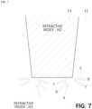
- FIG. 6 is a view showing the transmission, refraction, and reflection patterns according to an incident angle of light at an interface S at which medium A and medium B having different refractive indices come into contact.
- the light incident from medium A does not pass through the interface S and may proceed along the interface S.
- the light incident from medium A does not pass through the interface S and may be totally reflected.
- the incident angle when the incident angle is smaller than a critical angle as in a, among the light incident on the light-incident side surface of the shielding area 13 of the security film 100, the light may pass through the interface S of the shielding area 13 and proceed to the shielding area 13 and may be absorbed and lost within the shielding area 13.
- the light may proceed along the interface S of the shielding area 13 and may be reflected in the b' direction.
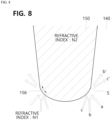
- FIG. 8 is a view showing how light is reflected and refracted on the surface of a light-incident surface side of the shielding portion 150 of the security film 100 according to one embodiment of the present invention.
- a tangential direction of a curved surface at the specific point becomes a direction of the media interface, and a perpendicular direction thereof becomes a direction with an incident angle of 0 degrees, which is indicated by a cross-dotted line in the drawing accordingly.
- the incident angle when the incident angle is smaller than a critical angle as in a, among the light incident on the first curved portion 156 of the light-incident surface of the shielding portion 150 of the security film 100, the light may pass through the interface S of the shielding area 13 and proceed to the shielding area 13, and may be absorbed and lost within the shielding area 13.
- the light when the incident angle is equal to the critical angle as in b, the light may proceed along the interface S and be reflected in the b' direction. At this time, since the direction of the media interface is toward the light-emitting surface side of the light transmitting portion 140, the reflected light may proceed toward the light transmitting portion 140.
- the incident angle is greater than the critical angle as in c
- the reflected light may proceed toward the light transmitting portion 140.
- the incident angle when the incident angle is smaller than the critical angle, the light may be lost, but when the incident angle is equal to or greater than the critical angle, the light may be reflected toward the light transmitting portion 140, thereby increasing the amount of light incident on the light transmitting portion 140.
- the shielding portion 150 may be formed of a resin mixed with carbon acting as light shielding particles, wherein a mixing ratio of the resin and the carbon may be 90 to 99% by weight of resin and 1 to 10% by weight of carbon. In this case, the carbon mixed in the resin may be uniformly distributed in the resin.
- the mixing ratio of the carbon mixed in the resin of the shielding portion 150 is only about 1 to 10%, since the shielding portion 150 is formed long in the vertical direction, as the light incident on the shielding portion 150 travels within the shielding portion 150, the light may continuously come into contact with the dispersed carbon particles, and absorbed or scattered and thus blocked.
- the ratio of the carbon is equal to or more than 10%
- the dispersibility of the carbon in the resin is not good due to the nature of carbon
- uniform dispersion of the carbon within the shielding portion 150 is disadvantageous
- the amount of carbon increases, since the amount of resin decreases, the amount of carbon may also increase at the interface of the shielding portion 150, which may drastically reduce the light reflection induction effect described above, thereby lowering the amount of light transmission of the security film.
- the security film 100 according to the present embodiment was tested when the first curved portion had a radius of curvature of 2 ⁇ m to 4 ⁇ m and the inner end portion was formed as a flat surface.
- the conventional security film 10 has the same structure as the security film according to the embodiment of the present invention, except that, as shown in FIG. 1 , the end portion of the light-incident surface side of the shielding area 13 was formed as a flat surface.
- the security film 200 may include a base layer 210 and a pattern layer 220.
- the base layer 210 is substantially the same as the base layer 110 in the above-described embodiment, detailed description thereof will be omitted.
- base portion 230 is substantially the same as the base portion 130 in the above-described embodiment, detailed description thereof will be omitted.
- the shielding portion 250 may also be the same as the shielding portion 150 in the above-described embodiment. However, at least a portion of the surface of the light-incident surface side of the lower side of the shielding portion 150 in the above-described embodiment may be formed round, but a surface of a light-incident surface side of a lower end of the shielding portion 250 in the present embodiment may be formed flat as needed. Of course, the present invention is not limited thereto, and at least a portion of the surface of the light-incident surface side may be formed round, similar to the shielding portion 150 in the above-described embodiment.
- At least a portion of a light-emitting surface 248 of the light transmitting portion 240 may be formed round so that light reflected from an inner side surface of the light-emitting surface 248 of the light transmitting portion 240 may be transmitted to the outside of the light-emitting surface 248 of the light transmitting portion 240.
- the light transmitting portion 240 may include a second side surface portion 242, an outer end portion 244, and a second curved portion 246.
- the second side surface portion 242 may form a side surface of the light transmitting portion 240, may be in contact with the shielding portion 250, and may extend in the thickness direction of the pattern layer 220.
- the outer end portion 244 may form an end portion of the light-emitting surface 248 of the light transmitting portion 240.
- the second curved portion 246 may be formed at a portion where the second side surface portion 242 and the outer end portion 244 are connected, and may be configured to be curved in a round shape.
- the outer side of the light-emitting surface 248 of the light transmitting portion 240 may be in contact with external air or another functional imparting layer to form an optical interface S.
- the refractive index of the light transmitting portion 240 may be formed to be greater than the refractive index of a material in contact with the outer side of the light-emitting surface 248, that is, the refractive index of air or the functional imparting layer.
- the light-emitting surface 248 of the light transmitting portion 240 may protrude further than the shielding portion 250, and this protruding height may be 0 ⁇ m to 5 ⁇ m.
- the radius of curvature of the second curved portion 246 may be greater than 0 ⁇ m and less than or equal to 100 ⁇ m.
- a width of the light-emitting surface 248 side of the light transmitting portion 240 may be about 30 ⁇ m to 40 ⁇ m
- the increase in transmittance may be minimal because the radius of curvature of the second curved portion 246 is too large compared to the width of the light transmitting portion 240 and becomes similar to a flat surface. Therefore, in order to effectively increase light transmittance, the radius of curvature of the second curved portion 246 may be greater than 0 ⁇ m and less than or equal to 20 ⁇ m.
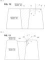
- FIG. 12 is a view how light is reflected and refracted on the light-emitting surface 14 of the light transmitting area in the conventional security film 10.
- the incident angle when the incident angle is smaller than a critical angle as in a, among the light incident on the light-emitting surface 14 of the light transmitting area of the security film 10, the light may be refracted and may pass through the light-emitting surface 14 and proceed in the a' direction.
- the light may proceed along the interface S of the light-emitting surface 14 and may be reflected in the direction b'.
- the incident angle is equal to or greater than the critical angle as in b or c
- the light may not pass through the light-emitting surface 14, and thus may not be used as meaningful light.
- the incident angle is equal to the critical angle as in b
- the light proceeds along the interface S and is reflected in the b' direction.
- the reflected light may pass through the light-emitting surface 248 and proceed in the b' direction.
- the light when the incident angle is greater than the critical angle as in c, the light may be totally reflected at the interface S and may be totally reflected toward the inside of the light transmitting portion 240 in the c' direction.
- the light when the incident angle is equal to the critical angle, the light may not pass through the light-emitting surface 248, but according to the present embodiment, even when the incident angle is equal to the critical angle, the light may pass through the light-emitting surface 248, thereby increasing light transmittance.
Landscapes
- Physics & Mathematics (AREA)
- General Physics & Mathematics (AREA)
- Optics & Photonics (AREA)
- Optical Elements Other Than Lenses (AREA)
Applications Claiming Priority (2)
| Application Number | Priority Date | Filing Date | Title |
|---|---|---|---|
| KR1020210168926A KR20230081135A (ko) | 2021-11-30 | 2021-11-30 | 고휘도 보안필름 |
| PCT/KR2022/018395 WO2023101289A1 (ko) | 2021-11-30 | 2022-11-21 | 고휘도 보안필름 |
Publications (2)
| Publication Number | Publication Date |
|---|---|
| EP4443201A1 true EP4443201A1 (de) | 2024-10-09 |
| EP4443201A4 EP4443201A4 (de) | 2025-10-15 |
Family
ID=86612679
Family Applications (1)
| Application Number | Title | Priority Date | Filing Date |
|---|---|---|---|
| EP22901647.2A Pending EP4443201A4 (de) | 2021-11-30 | 2022-11-21 | Sicherheitsfilm mit hoher helligkeit |
Country Status (5)
| Country | Link |
|---|---|
| US (1) | US20250028095A1 (de) |
| EP (1) | EP4443201A4 (de) |
| KR (1) | KR20230081135A (de) |
| CN (1) | CN118339488A (de) |
| WO (1) | WO2023101289A1 (de) |
Families Citing this family (3)
| Publication number | Priority date | Publication date | Assignee | Title |
|---|---|---|---|---|
| DE102022134518B3 (de) * | 2022-12-22 | 2024-03-28 | Sioptica Gmbh | Optisches Element, Verfahren zu seiner Herstellung sowie Beleuchtungseinrichtung |
| CN116841069A (zh) * | 2023-07-28 | 2023-10-03 | 惠科股份有限公司 | 显示模组、驱动方法和显示装置 |
| KR102773644B1 (ko) * | 2024-07-24 | 2025-02-27 | (주)우진에이엠티 | 보안 필름 |
Family Cites Families (10)
| Publication number | Priority date | Publication date | Assignee | Title |
|---|---|---|---|---|
| KR100783645B1 (ko) * | 2006-11-06 | 2007-12-07 | 엘지전자 주식회사 | 플라즈마 디스플레이 장치 |
| KR20080055335A (ko) * | 2006-12-15 | 2008-06-19 | 삼성코닝정밀유리 주식회사 | 디스플레이 장치용 외광 차폐 필름, 이의 제조 방법 및이를 포함하는 디스플레이 장치용 필터 |
| EP2208096B1 (de) * | 2007-10-16 | 2019-11-27 | 3M Innovative Properties Company | Lichtkontrollfilm mit höherer durchlässigkeit |
| US9244204B2 (en) * | 2009-10-27 | 2016-01-26 | Dai Nippon Printing Co., Ltd. | Image source unit and image display unit |
| WO2018084280A1 (ja) * | 2016-11-07 | 2018-05-11 | 富士フイルム株式会社 | 光吸収体含有フィルムおよびバックライトユニット |
| US20190049776A1 (en) * | 2017-08-08 | 2019-02-14 | Shin-Etsu Polymer Co., Ltd. | Light transmission direction control sheet |
| KR102140488B1 (ko) * | 2018-07-04 | 2020-08-03 | 신화인터텍 주식회사 | 기능성 광학 시트 및 그 제조 방법 |
| KR102165201B1 (ko) * | 2020-06-22 | 2020-10-13 | 주식회사 세화 | 프라이버시 필터 |
| CN213618709U (zh) * | 2020-09-30 | 2021-07-06 | 深圳凯茵思科技有限公司 | 一种防窥膜 |
| US12310154B2 (en) * | 2020-11-30 | 2025-05-20 | Nichia Corporation | Light-transmissive member and method of manufacturing the same, optical member, and light emitting device |
-
2021
- 2021-11-30 KR KR1020210168926A patent/KR20230081135A/ko active Pending
-
2022
- 2022-11-21 WO PCT/KR2022/018395 patent/WO2023101289A1/ko not_active Ceased
- 2022-11-21 CN CN202280079433.3A patent/CN118339488A/zh active Pending
- 2022-11-21 US US18/714,712 patent/US20250028095A1/en active Pending
- 2022-11-21 EP EP22901647.2A patent/EP4443201A4/de active Pending
Also Published As
| Publication number | Publication date |
|---|---|
| EP4443201A4 (de) | 2025-10-15 |
| US20250028095A1 (en) | 2025-01-23 |
| KR20230081135A (ko) | 2023-06-07 |
| CN118339488A (zh) | 2024-07-12 |
| WO2023101289A1 (ko) | 2023-06-08 |
Similar Documents
| Publication | Publication Date | Title |
|---|---|---|
| US20250028095A1 (en) | High-brightness security film | |
| US7534024B2 (en) | Optical deflector element and light source device | |
| US7599117B2 (en) | View angle control sheet and display device | |
| KR100685548B1 (ko) | 광원 장치 | |
| KR101182261B1 (ko) | 도광체, 은폐 구조체, 이것들을 구비한 조명장치, 표시장치 | |
| KR101605539B1 (ko) | 시야각 제한 시트 및 플랫 패널 디스플레이 | |
| US20060245060A1 (en) | Viewing-angle control sheet | |
| KR101048201B1 (ko) | 광원 장치 및 광편향 소자 | |
| US20110280044A1 (en) | Optical member, light source apparatus, display apparatus, and terminal apparatus | |
| KR19990083239A (ko) | 도광판, 표면 광원 장치 및 반사형 액정 디스플레이 | |
| CN100445868C (zh) | 菲涅尔透镜片、透射型屏幕和背面投射型显示装置 | |
| CN110088674B (zh) | 一种背光模组、显示装置以及电子设备 | |
| US20240160060A1 (en) | Anti-glare and anti-reflection film, polarizer and display panel | |
| EP1521114A1 (de) | Reflektor und Flüssigkristallanzeigevorrichtung unter dessen Verwendung | |
| JP4121997B2 (ja) | 視野角制御シート及びこれを用いた画像表示装置 | |
| CN111045248A (zh) | 显示设备 | |
| JP2025013837A (ja) | 光学フィルム | |
| KR20190081027A (ko) | 차폐 성능이 향상된 확산시트 및 이를 구비한 백라이트 유닛 | |
| KR20090086759A (ko) | 정면 휘도가 개선된 길이방향 웨이브 패턴의 프리즘 산을갖는 프리즘 시트, 이를 채용한 백라이트 유니트, 및 상기백라이트 유니트를 구비한 액정표시장치 | |
| US20240393637A1 (en) | Polarizer, display panel, and display device | |
| EP4439160A1 (de) | Anzeigevorrichtung | |
| JP5012221B2 (ja) | バックライトユニット、およびディスプレイ装置 | |
| TW201700429A (zh) | 玻璃及玻璃構件 | |
| JP4400867B2 (ja) | 光偏向素子及び光源装置 | |
| CN106547145A (zh) | 背光模组与显示装置 |
Legal Events
| Date | Code | Title | Description |
|---|---|---|---|
| STAA | Information on the status of an ep patent application or granted ep patent |
Free format text: STATUS: THE INTERNATIONAL PUBLICATION HAS BEEN MADE |
|
| PUAI | Public reference made under article 153(3) epc to a published international application that has entered the european phase |
Free format text: ORIGINAL CODE: 0009012 |
|
| STAA | Information on the status of an ep patent application or granted ep patent |
Free format text: STATUS: REQUEST FOR EXAMINATION WAS MADE |
|
| 17P | Request for examination filed |
Effective date: 20240625 |
|
| AK | Designated contracting states |
Kind code of ref document: A1 Designated state(s): AL AT BE BG CH CY CZ DE DK EE ES FI FR GB GR HR HU IE IS IT LI LT LU LV MC ME MK MT NL NO PL PT RO RS SE SI SK SM TR |
|
| DAV | Request for validation of the european patent (deleted) | ||
| DAX | Request for extension of the european patent (deleted) | ||
| A4 | Supplementary search report drawn up and despatched |
Effective date: 20250917 |
|
| RIC1 | Information provided on ipc code assigned before grant |
Ipc: G02B 5/30 20060101AFI20250911BHEP Ipc: G02B 27/09 20060101ALI20250911BHEP |